Power Meter 5000 PM5000 F - Electric meter BOSCH - Free user manual and instructions
Find the device manual for free Power Meter 5000 PM5000 F BOSCH in PDF.

User questions about Power Meter 5000 PM5000 F BOSCH
0 question about this device. Answer the ones you know or ask your own.
Ask a new question about this device
Download the instructions for your Electric meter in PDF format for free! Find your manual Power Meter 5000 PM5000 F - BOSCH and take your electronic device back in hand. On this page are published all the documents necessary for the use of your device. Power Meter 5000 PM5000 F by BOSCH.
USER MANUAL Power Meter 5000 PM5000 F BOSCH
natural_image
Technical line drawing of a mechanical component with mounting holes and housing (no text or symbols)Съдържание
text_image
Technical diagram of an electrical fuse box with labeled components and a warning label for installationtext_image
Technical diagram showing exploded view of an electrical fuse box with labeled components and a warning symbol on a surface.Closed contact Tarif 2
RS485 Modbus s Masterem
flowchart
graph TD
    T["7"] --> 8["8"]
    T --> 9["9"]
    8 --> A["A"]
    8 --> B["B"]
    9 --> A
    9 --> B
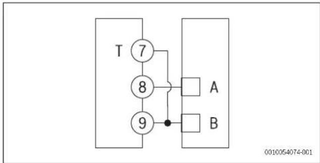
Obr. 27 Schéma RS485 Modbus Master

| Features Unit Power Meter 5000 | ||
| Electrical specifications | ||
| Power | - | Self-powered (via measured voltage) |
| Consumption | WVA | ≤1≤10 |
| Base current A 5 | ||
| Maximum current (continuing) A 65 | ||
| Minimum current A 0.25 | ||
| Start up current A 0.02 | ||
| Working voltage | - | AV2: 208-400 V L-L ac (mains voltage) |
| Frequency | Hz | 45-65 Hz |
| Accuracy class | -- | Active energy: Class 1 (EN62053-21)Reactive energy: Class 2 (EN62053-23) |
| Environmental specifications | ||
| Working temperature | °C°F | -25 to +65-13 to +149 |
| Storage temperature | °C°F | -30 to +80-22 to +176 |
| R.H.:1) | - From 0 to 90% non-condensing @ 40°C | |
| Output specifications | ||
| Modbus RS485 port output | - | Modbus RTU protocol |
| General features | ||
| Terminals | mm2mm2 | 1-6: section 2.5-16 mm2, torque 2.8 Nm7-12, N: section 1.5 mm2, torque 0.4 Nm |
| Protection grade | -- | Front: IP51Terminals: IP20 |
| Dimensions | mm | (H x W x D) 91 x 54 x 63 |
1) Intended for indoor use only
Tab. 28 Technical data
Indholdsfortegnelse 1 Symbolforklaring og sikkerhedsanvisninger
4 Installation ....29
4.1 Tilslutningsskemaer....29
4.2 Oversigt over menutrae ....30
4.3 Menukommandoer....30
4.4 Indstilling af en parameter....31
4.5 Målingsmenu .... 31
4.6 Parametermenu....33
4.7 Informationsmenu....34
5 Opstart....34
5.1 Tilslutningsmuligheder ....34
5.1.1 LED-specifikationer .... 34
5.1.2 LED-status for....35
text_image
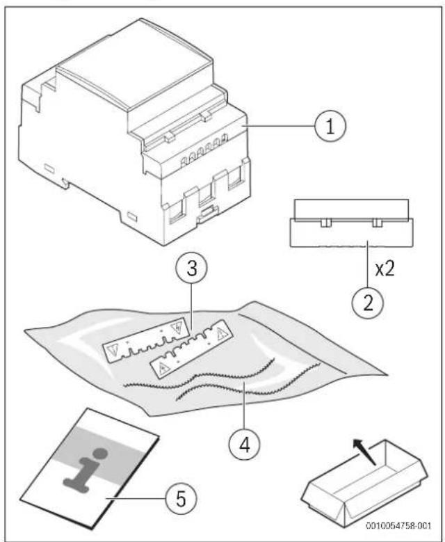
Technical diagram showing exploded view of an electrical fuse box with labeled components and a warning symbol on a surface.Fig. 37 Leveringsomfang
[1] Strømmåler
[2] Klemmedæksler, der kan plomberes
[3] Klemmebeskyttelsesafdækninger
[4] Plomberingstråde
[5] Installationsvejledning
2.3 Produkt oversigt
text_image
POWER METER 5000 1 2 3 4 5 6 7 8 9 10 11 12 0010054070-001Closed contact Tarif 2
www.bosch-homecomfortgroup.com/en/company/legal-topics/weee/
4 Installation....39
4.1 Anschlusspläne....40
4.2 Übersicht Menüstruktur....41
4.3 Menübefehle....41
4.4 Parameter einstellen ....42
4.5 Messwertmenü....42
4.6 Parametermenü....44
4.7 Informationsmenü ....45
text_image
Technical diagram of an electrical fuse box with labeled components and a warning iconClosed contact Tarif 2
text_image
Technical diagram showing exploded view of an electrical fuse box with labeled components and a warning icon.Table of contents 1 Explanation of symbols and safety instructions
1 Explanation of symbols and safety instructions ..... .61
1.1 Explanation of symbols ....61
1.2 General safety instructions ....61
2 Product Information....62
2.1 Declaration of Conformity ....62
2.2 GB Importer ....62
2.3 Simplified UK/EU Declaration of conformity regarding radio equipment ....62
2.4 Regulations....62
2.5 Scope of delivery ....63
2.6 Product overview ....63
3 Pre-installation....63
3.1 Product dimensions....63
3.2 Location ....64
4 Installation....64
4.1 Connection diagrams....64
4.2 Menu map overview ....65
4.3 Menu commands ....65
4.4 Setting a parameter ....66
4.5 Measurement menu....66
4.6 Parameter menu....68
4.7 Information menu....69
5 Commissioning....70
5.1 Connectivity....70
5.1.1 LED specifications....70
5.1.2 LED status of the Power Meter 5000 ....70
6 Inspection and maintenance....70
6.1 Cleaning the Power Meter 5000....70
7 Troubleshooting....70
7.1 Connection check....70
7.1.1 Initial assumptions....70
7.1.2 Controls and signals....70
8 Environmental protection and disposal .....71
9 Data Protection Notice ....71
10 Technical information ....72
10.1 Technical data....72
1.1 Explanation of symbols
Warnings
In warnings, signal words at the beginning of a warning are used to indicate the type and seriousness of the ensuing risk if measures for minimising danger are not taken.
The following signal words are defined and can be used in this document:

DANGER
DANGER indicates that severe or life-threatening personal injury will occur.

WARNING
WARNING indicates that severe to life-threatening personal injury may occur.

CAUTION
CAUTION indicates that minor to medium personal injury may occur.
NOTICE
NOTICE indicates that material damage may occur.
Important information

The info symbol indicates important information where there is no risk to people or property.
Additional symbols
| Symbol | Meaning |
| ▶ | a step in an action sequence |
| → | a reference to a related part in the document |
| • | a list entry |
| - | a list entry (second level) |
Table 71
1.2 General safety instructions
⚠️Notices for the target group
These installation instructions are intended for gas, plumbing, heating and electrical contractors. All instructions must be observed. Failure to comply with instructions may result in material damage and personal injury, including danger to life.
▶ Read the installation, service and commissioning instructions (heat source, heating controller, pumps, etc.) before installation.
▶ Observe the safety instructions and warnings.
▶ Follow national and regional regulations, technical regulations and guidelines.
▶ Record all work carried out.
Intended use
The Power Meter 5000 is a 65 A direct connection three-phase energy analyser with Modbus. It is intended to:
• Measure active and reactive energy.
- Sum (easy connection mode on) or separate imported energy from exported energy.
- Manages two energy tariffs using a digital input or Modbus command.
- Is equipped with the output to communicate measurements via RS485 Modbus port.
- Measures three DIN modules, with backlit LCD display with sensitive touch screen areas for page scrolling and parameters setting.
Using the Power Meter 5000 for any other purpose will be considered incorrect use. Bosch accepts no liability for any damage resulting from such use.
Electrical work
Electrical work must only be carried out by electrical installation contractors.
Before starting electrical work:
▶ Isolate all poles of the mains voltage and secure against reconnection.
▶ Make sure the mains voltage is disconnected.
▶ Do the earthing and the short-circuiting.
▶ Cover up or block off live parts in the vicinity. Reactivation is carried out in reverse order.
▶ Observe the wiring diagrams of other system components as well.
▶ Make sure to follow the relevant electrotechnical regulations at all times.
▶ Make sure to identify risks and avoid potential hazards.
National safety and accident prevention rules must be observed by the user and the approved contractors when providing and handling the charging system.
The improper use as well as the non-observance of the operating instructions:
- Can endanger your life.
- Can endanger your health.
- Can damage the charging system and the vehicle.
⚠️ Danger to life through electric shock!
Touching live parts can result in an electric shock.
Before carrying out work on electrical components, isolate them from the power supply (230 V AC) and secure against unintentional reconnection.
⚠ Inspection and maintenance
Regular inspection and maintenance are prerequisites for safe and environmentally compatible operation of the system.
We recommend arranging an annual maintenance and inspection contract with the manufacturer.
▶ Have work carried out only by an approved contractor.
▶ Eliminate all defects identified immediately.
Every situation that deviates from the conditions described in the instructions must be assessed by an approved specialist. If there is approval for this, the specialist must specify a catalogue of maintenance requirements, which take wear and the particular operating conditions into account, and which comply with the standards and requirements of the country and the usage.
2 P r o d u c t l n
2.1 Declaration of Conformity
The design and operating characteristics of this product comply with the British, European and supplementary national requirements.


The UKCA and CE markings declare that the product complies with all the applicable British and European legislation, which is stipulated by attaching these markings.
You can request the complete text of the Declaration of Conformity from the UK address indicated in this document.
2.2 GB Importer
Bosch Thermotechnology Ltd.
Cotswold Way, Warndon
Worcester WR4 9SW / UK
2.3 Simplified UK/EU Declaration of conformity regarding radio equipment
Bosch Thermotechnik GmbH hereby declares, that the product Power Meter 5000 described in these instructions complies with the Directive UK S.I. 2017/1206 (UK) 2014/53/EU.
You can request the complete text of the UK/EU Declaration of Conformity from the UK address indicated in this document.
2.4 Regulations
In order to ensure installation and operation of the product in accordance with the regulations, please observe all the applicable national and regional regulations as well as all technical rules and guidelines.
You can find a list of the most relevant British and European directives and regulations in the table below.
| EU legislation UK legislation | |
| Electromagnetic Compatibility - Directive 2014/30/EU | Electromagnetic Compatibility Regulations 2016 |
| Low Voltage Directive 2014/35 Electrical Equipment (Safety) Regulations 2016 | |
| Radio Equipment - Directive 2014/53/EU | Radio Equipment Regulations 2017 |
| Pressure Equipment - Directive 2014/68/EU | Pressure Equipment (Safety) Regulations 2016 |
| Gas Appliances - Regulation (EU) 2016/426 | Regulation 2016/426 on gas appliances as brought into UK law and amended |
| Machinery Directive 2006/42/EC Supply of Machinery (Safety) Regulations 2008 | |
| Ecodesign Directive 2009/125/EC | The Ecodesign for Energy-Related Products Regulations 2010 |
| Energy Labelling Regulation (EU) 2017/1369 | Energy Labelling Regulation (EU) 2017/1369 (as retained in UK law and amended) |
| Restriction of the Use of certain Hazardous Substances in Eletrical and Electronic Equipment (RoHS) - Directive 2002/95/EC | The Restriction of the Use of Certain Hazardous Substances in Eletrical and Electronic Equipment Regulations 2012 |
| European Directive 2012/19/EC on old electronic and electrical appliances | (UK) Waste Electrical and Electronic Equipment Regulations 2013 (as amended) |
Table 72
2.5 Scope of delivery
text_image
Technical diagram showing exploded view of an electrical fuse box with labeled components and a warning labelFig. 91 Scope of delivery
[1] Power Meter
[2] Sealable terminal caps
[3] Terminal protection covers
[4] Sealing wires
[5] Installation manual
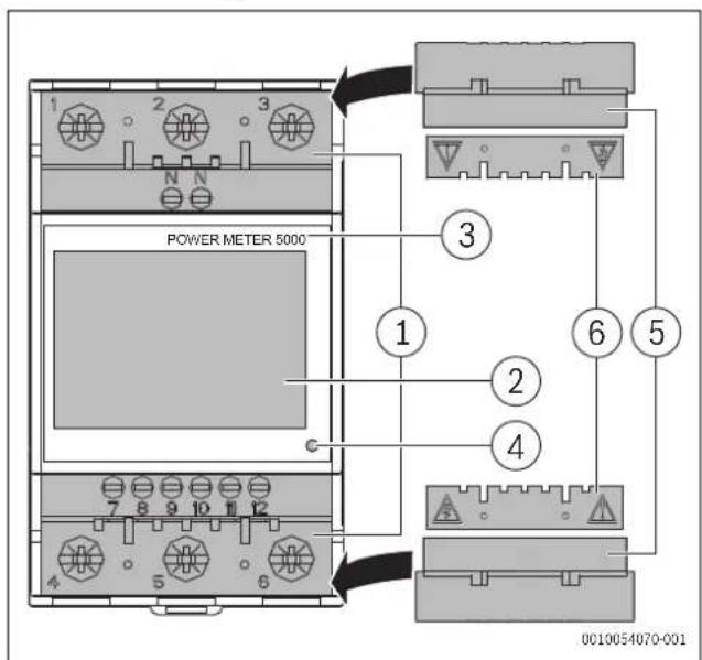
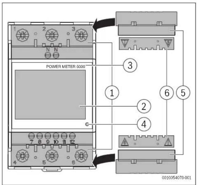
2.6 Product overview
text_image
POWER METER 5000 0010054070-001Fig. 92 Product overview
[1] Current and communication connection terminals
[2] Backlit LCD display with sensitive touch screen area
[3] Model
[4] LED
[5] Sealable terminal caps
[6] Terminal protection covers
text_image
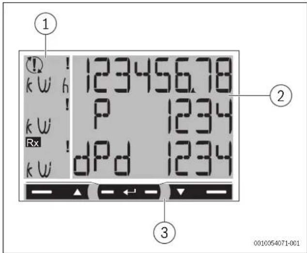
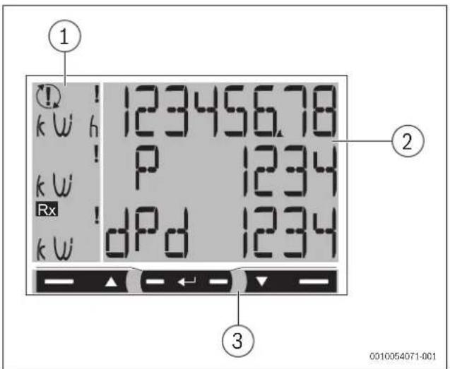
1 k W h ! 12345678 k W ! P 1234 Rx ! dPd 1234 k W 2 3 0010054071-001Fig. 93 Product overview
[1] Unit of measure and signal area
[2] Area with specific section information
[3] Command area

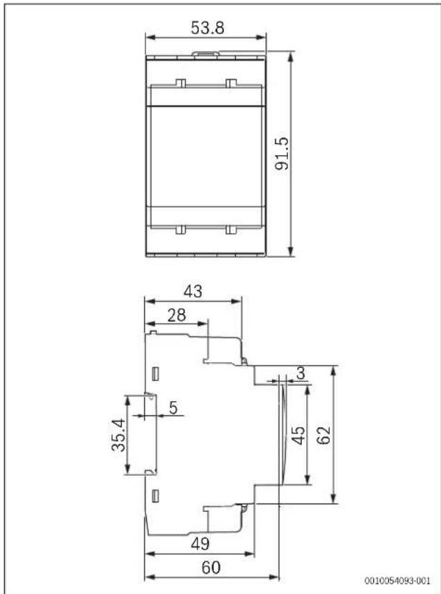
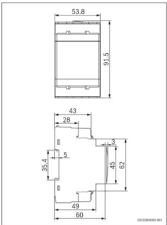
3.1 Product dimensions
Dimensions
text_image
53.8 91.5 43 28 3 5 35.4 45 62 49 60 0010054093-001Fig. 94 Product dimensions
3.2 Location
Location requirements
Consider the following when selecting an installation location:
▶ Install the Power Meter 5000in a switchboard close to a grid connection point.
NOTICE
Danger to the product
The non-compliance with the instructions mentioned above may cause product damage and its malfunctioning.
4 Installation
⚠ Safety notice
The energy analyser must only be installed by qualified/authorized personnel.

WARNING
Live parts. Risk of burn, heart attack and other possible injuries
▶ Disconnect the power supply and electrical load before installing the analyser.
▶ Protect the terminals with covers.

WARNING
Risk of electrocution!
The protection cover of the wires must be correctly installed, before connecting any input/output wire.
▶ Insert the metallic part of the wire or the ferrule completely into the terminal.
4.1 Connection diagrams
Three-phase system, 4-wire
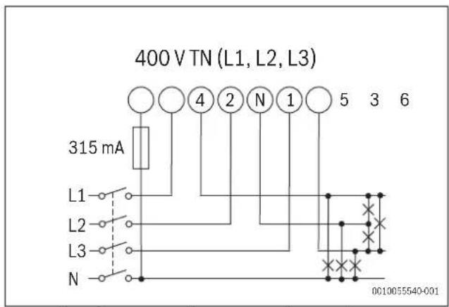
text_image
400 V TN (L1, L2, L3) 315 mA L1 L2 L3 N 4 2 N 1 5 3 6 0010055540-001Fig. 95 Three-phase system diagram, 4-wire (400 V TN)
▶ Install a 315 mA fuse, if required by local regulations.
Two-phase system, 3-wire
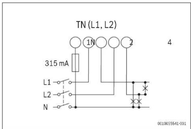
text_image
TN (L1, L2) 315 mA L1 L2 N 1N 2 4 0C10055541-001Fig. 96 Two-phase system diagram, 3-wire (TN)
▶ Install a 315 mA fuse, if required by local regulations.
Three-phase system, 3-wire
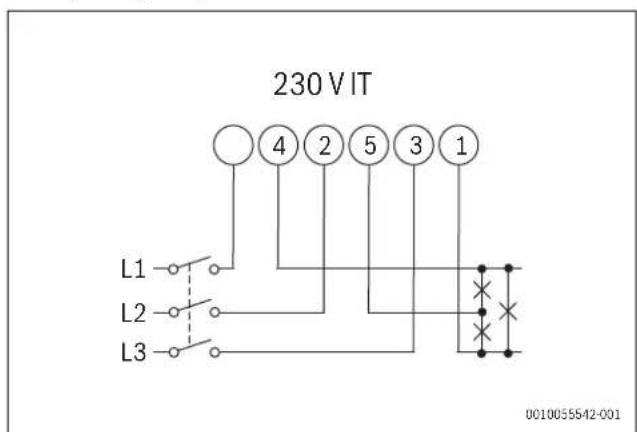
text_image
230 V IT L1 4 2 5 3 1 L2 L3 0010055542-001Fig. 97 Three-phase system diagram, 3-wire (230 V IT)
Digital input
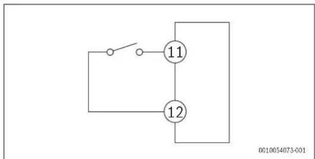
text_image
11 12 0010054073-001Fig. 98 Digital input diagram
Open contact Tariff 1
Closed contact Tariff 2
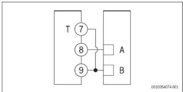
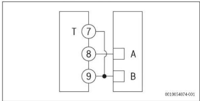
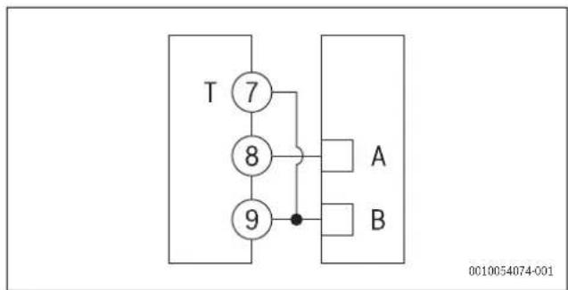
RS485 Modbus with Master
flowchart
graph TD
    T["7"] --> A["A"]
    T["7"] --> B["B"]
    T["7"] --> 8["8"]
    T["7"] --> 9["9"]
    8 --> A
    8 --> B
    9 --> A
    9 --> B
Fig. 99 RS485 Modbus Master diagram
i
Additional instruments with RS485 are connected in parallel.
▶ The serial output must only be terminated on the last network device connecting terminals 9 and 7 (T).
▶ Use a signal repeater for connections longer than 1000 m.
▶ Only a maximum of 247 transceivers is possible on the same bus.
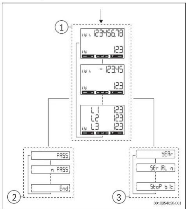
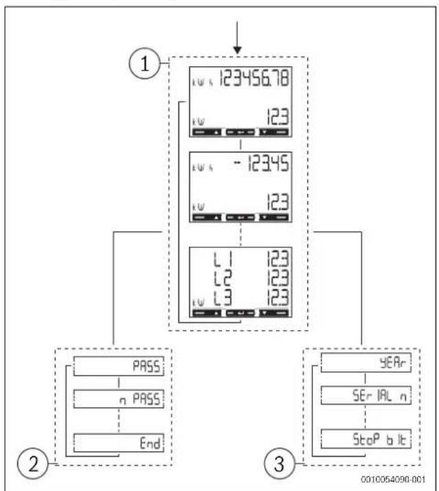
4.2 Menu map overview
flowchart
graph TD
    A["1"] --> B["2"]
    B --> C["PASS"]
    B --> D["n PASS"]
    B --> E["End"]
    A --> F["3"]
    F --> G["YEAR"]
    F --> H["SE r IAL n"]
    F --> I["StoP b lt"]
    style A fill:#f9f,stroke:#333
    style B fill:#ccf,stroke:#333
    style F fill:#cfc,stroke:#333
Fig. 100 Menu map
| Menu Area Function | ||
| 1 | M e menu | Measurements are displayed by default when switching on the menuPages are characterized by the reference unit of measure |
| 2 | Parameter menu | The parameters settings pages are displayed in this menuTo access this menu a login password is required |
| 3 | Information menu | These menu pages display information and allow setting parameters without having to enter a password |
Table 73 Menu map functions
4.3 Menu commands
Menu overview
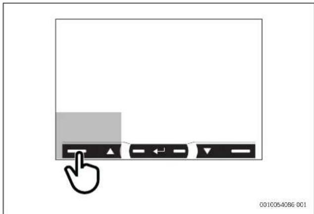
text_image
0010054086 001Fig. 101 Menu display screen
| Navigation Parameter settings | |
| View the next page | Increase a parameter valueView the next value option |
Table 74 Menu command settings
Menu overview
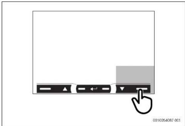
text_image
0010054087-001Fig. 102 Menu display screen
| Navigation Parameter settings | |
| View the previous page | Decrease a parameter valueView the previous value option |
Table 75 Menu command settings
Menu overview
text_image
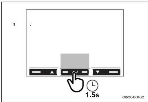
n t L 1.5s 0010054088-001Fig. 103 Menu display screen
| Navigation Parameter settings | |
| Open the parameter menuExit the parameter menu (page End) | Confirm a valueOpen the parameter settings page |
Table 76 Menu command settings
Menu overview

text_image
1.5s 0010054089-001Fig. 104 Menu display screen
| Navigation Parameter settings | |
| Open the information menuExit the information menu | Quickly confirm the 0000 default password |
Table 77 Menu command settings

After 120s of disuse, the measurement page set in HoME will be displayed. The command will only work if pressed twice.

Upon first touching the command area, the display back light will turn on.
4.4 Setting a parameter

flowchart
graph TD
    A["P Int 01"] --> B["1.5s"]
    B --> C["P Int 02"]
    C --> D["PRG"]
    D --> E["x3"]
    E --> F["P Int 03"]
    F --> G["PRG"]
    G --> H["1.5s"]
    H --> I["P Int 04"]
    I --> J["PRG"]
    J --> K["x2"]
    K --> L["P Int 05"]
    L --> M["PRG"]
    M --> N["1.5s"]
    N --> O["OK"]
    O --> P["NO OK"]
    P --> Q["P Int 24"]
    Q --> R["PRG Err"]
    R --> S["L 2s"]
Fig. 105 Parameter procedure
To set the parameter P int=24, the following steps are required:
• The first display value is the current one.
- Settings are applied when the value is confirmed.
- | f Prg appears, the value is being edited.
- | f Err appears, the set value is out of range.
• After 120s of disuse on a value being set, the title page is displayed (P int) and Prg disappears.
• After another 120s, the measurement page set in HoME will return.
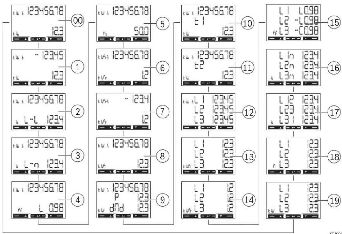
4.5 Measurement menu

if the display mode and tariff are set as Mode = Full, tariFF = ON, MEAsure = B, System = 3Pn, all pages from 00 to 19 are displayed on the screen.
If the default values of the display mode and tariff are set (Mode = Full, tariFF = OFF, MEAsure = A, System = 3Pn), only the pages 00, 2, 3, 4, 5, 6, 8, 9, 12, 13, 14, 15, 16, 17, 18 and 19 are displayed.
Measurement pages
text_image
k w h 123456.78 00 k w h 123456.78 5 k w h 123456.78 10 k w h 123456.78 15 L1 L0.98 L2 -L0.98 L3 -C0.98 1 k w h - 12345 k w h 123456.78 6 k w h 123456.78 11 k w h 123456.78 16 L In 1234 L2n 1234 L3n 1234 2 k w h 123456.78 7 k w h - 1234 k w h 123456.78 12 k w h L1 12345 L2 12345 L3 12345 17 L I2 1234 L23 1234 L3I 1234 3 k w h 123456.78 8 k w h 123456.78 13 L I 123 L2 123 L3 123 18 L I 123 L2 123 A L3 123 4 k w h 123456.78 P 123 k w dnd 123 9 L I 12 L2 12 L3 12 19 L I 123 L2 123 K W L3 123Fig. 106 Measurement pages of the display screen
Pages Description
| 00 | Total imported active energy ^1) Total active power |
| 01 | Total exported active energy ^2) Total active power |
| 02 | Total imported active energy ^1) Average system mains voltage |
| 03 | Total imported active energy ^1) Average system phase voltage |
| 04 | Total imported active energy ^1) Power factor (L = inductive, C = capacitive) |
| 05 | Total imported active energy ^1) Frequency |
| 06 | Total imported reactive energy ^1) Total reactive power |
| 07 | Total exported reactive energy ^2) Total reactive power |
| 08 | Total imported active energy ^1) Total apparent energy |
| 09 | Total imported active energy ^1) Requested average power (P = demand) calculated for the set interval. The value remains the same for the entire interval. It is = 0 during the first start up interval.Maximum requested power (dMd = Peak demand) reached since last reset |
| 10 | Active energy imported with tariff 1 (t1). Displayed if tariff management is on (Tariff = on).Active power |
| 11 | Total active energy imported with tariff 2 (t2). Displayed if tariff management is on (Tariff = on).Active power |
Table 78 General measurement pages description
1) For Total imported active energy and Total imported reactive energy parameters, if easy connection is on (Measure = A), it indicates total energy without considering the direction.
^2) The Total exported active energy and Total exported reactive energy parameters display whether imported and exported energy are measured separately (Measure = b).
Single phase measurement pages
The phase measurement pages and the indicated information for each phase is dependant on the type of system analysed.
Pages Description
| 12 Imported active energy. If easy connection is on (Measure = A), it indicates total energy without considering the direction. | |
| 13 Apparent power | |
| 14 Imported reactive energy | |
| 15 | Power factor (L= inductive, C= capacitive) |
| 16 Phase voltage | |
| 17 Mains voltage | |
| 18 Current | |
| 19 Active power | |
Table 79 Single phase measurement pages settings
Measurement faults
If the measured signal exceeds the admitted analyser limits, a specific message appears:
▶ EEE blinking: the measured value is out of limits.
▶ EEE on: the measurement depends on a value that is out of limits

The active and reactive energy measurements are displayed but do not change.
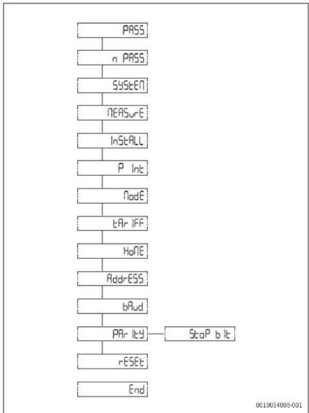
4.6 Parameter menu
Shared pages overview
flowchart
graph TD
    A["PASS"] --> B["n PASS"]
    B --> C["SYSTEM"]
    C --> D["NEASURE"]
    D --> E["Install"]
    E --> F["P Int"]
    F --> G["Node"]
    G --> H["tAr IFF"]
    H --> I["Home"]
    I --> J["Addr-ESS"]
    J --> K["bAud"]
    K --> L["PAR lty"]
    L --> M["rESET"]
    M --> N["End"]
    O["Stop bit"] --> L
Fig. 107 Parameter menu of the display screen

Default values are highlighted.
Table 80 Page settings
| Pages Code Description Values | |||
| Shared pages settings | |||
| PASS | P1 | Enter current password | Current password |
| nPASS | P2 | Change password | Four digits (0000–9999) |
| SYStEM P3 System type | 3Pn: three phase system, 4-wire3P: three-phase system, 3-wire2P: two-phase system, 3-wire | ||
| MEASurE P6 Measurement type | A: easy connection, measures total energy without considering the directionb: separately measures imported and exported energy | ||
| InStALL P7 Connection check | On: enabledOff: disabled | ||
| P int | P8 | Average power calculation interval (minutes) | 1-30 |
| Pages | Code | Description | Values |
| MOdE P9 Display mode | Full:complete modeEasy:reduced modeMeasurements not displayed are still sent via serial port | ||
| tArIFF P10 Tariff management | On:enabledOff:disabled | ||
| HoME P11 | The Measurement page is displayed when turned on and after 120 seconds of disuse | For full display mode (Mode = Full): 0-16-19For reduced display mode (Mode = Easy): 0-3, 6, 7, 10, 11, 18To learn the page code see Measurement menu (→ 106) | |
| AddrESS | P14 | Modbus address | 0-20-247 |
| bAUd | P15 | Baud rate (kbps) | 9.6/ 19.2/ 38.4/ 57.6/ 115.2 |
| PARITY | P16 | Parity | Even/no |
| STOP bit | P16-2 | Only if no parity. Stop bit | 1/2 |
| rESET P17 | Enable energy tariff, maximum requested power, partial energy and partial reactive energy reset (the last two are only sent via serial port) | No:cancel resetYes: enable reset | |
| End | P18 | Return to the initial measurement page | - |
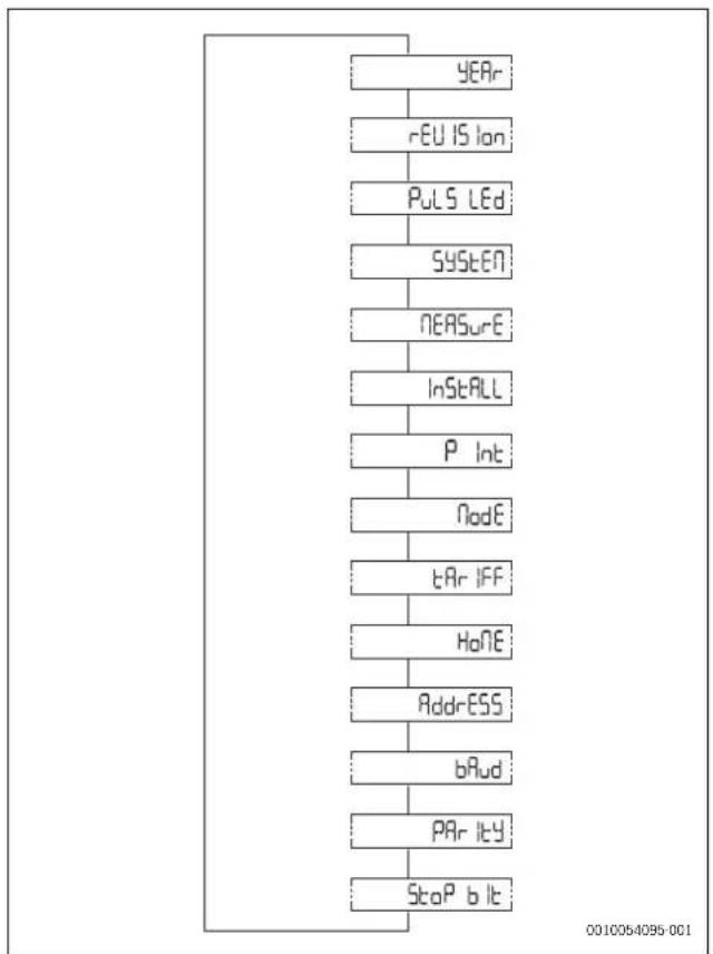
4.7 Information menu
Pages overview
flowchart
graph TD
    A["YEAR"] --> B["rEU IS Ion"]
    B --> C["Puls LEDs"]
    C --> D["SYStEN"]
    D --> E["NEASure"]
    E --> F["InstALL"]
    F --> G["P Int"]
    G --> H["Node"]
    H --> I["tAr IFF"]
    I --> J["Home"]
    J --> K["Addr-ESS"]
    K --> L["bRud"]
    L --> M["PR ity"]
    M --> N["Stop bit"]
Fig. 108 Information menu of the display screen
| Page | Code | Description |
| Shared pages settings | ||
| YEAr | InFO 1 | Year of manufacture |
| SErIAL n | InFO 2 | Serial number which corresponds to the one indicated on the front print, without the initial 'K' |
| rEVISlon | InFO 3 | Firmware revision - B.nn ^1) |
| Page | Code | Description |
| PuLS Led | InFO 4 | Front LED pulse weight |
| SYStEM P3 System type | ||
| MEASurE | P6 Measurement type | |
| InStALL | P7 | Enabling connection check |
| P int | P8 | Requested average power calculation interval |
| ModE | P9 Display mode | |
| tArIFF | P10 | Enabling tariff management and any current tariff |
| HoME | P11 | Measurement page set as the home page |
| AddrESS | P14 Modbus address | |
| bAUd | P15 Baud rate | |
| PARITY | P16 Parity | |
| StoP bit P16-2 | Stop bit | |
1) nn: sequential revision number (i.e.: 00, 01, 02).
Table 81 Pages settings
5 Commissioning
5.1 Connectivity
5.1.1 LED specifications
| LED features | |
| Pulse weight 1000 impulses/kWh (EN50470-3, EN62052-11) | |
| Duration 90 ms | |
| Color Red and orange | |
Table 82 LED features
5.1.2 LED status of the Power Meter 5000
| LED display | Status |
| Blinking red | 1 pulse = 1 Wh |
| Orange on | Total active power negative. Control will only run if the imported and exported energies are measured separately (Measure = b). |
Table 83 LED status of the Power Meter 5000
6 Inspection and maintenance
6.1 Cleaning the Power Meter 5000
NOTICE
Possible damage to the appliance!
To clean the appliance:
▶ Make sure to not use aggressive cleaning agents (e.g. petroleum ether, acetone, ethanol, methylated spirit-based glass cleaner, abrasives or solvents) when cleaning the Power Meter 5000.
▶ Make sure to use a mild detergent solution (e.g. washing-up liquid, neutral cleaner) and a soft, dampened cloth for cleaning the instrument display.
7 T r o u b l e s h
7.1 Connection check
The analyser checks whether connections are correct and signals any faults. The check can be disabled using the Install, parameter, see Parameter menu ( Fig. 107 "Parameter menu of the display screen").
7.1.1 Initial assumptions
The check is based on some initial assumptions on the system to be measured. Specifically, it is assumed that each system phase is characterized by:
▶ A load with PF>0.766 (<40°) power factor if inductive or PF>0.996 (<5°) if capacitive.
▶ Current at least equal to 10% rated current (65 A).
7.1.2 Controls and signals
Following are the controls in the order in which they are run and the corresponding signals:
| Signal | Control |
| Voltage order of the involved phase. | |
| Current direction^1) of the involved phase. |
1) The control will only run if the imported and exported energies are measured separately (Measure = b).
Table 84 Controls and signals list
8 Environmental protection and disposal
Environmental protection is a fundamental corporate strategy of the Bosch Group.
The quality of our products, their economy and environmental safety are all of equal importance to us and all environmental protection legislation and regulations are strictly observed.
We use the best possible technology and materials for protecting the environment taking account of economic considerations.
Packaging
Where packaging is concerned, we participate in country-specific recycling processes that ensure optimum recycling.
All of our packaging materials are environmentally compatible and can be recycled.
Used appliances
Used appliances contain valuable materials that can be recycled.
The various assemblies can be easily dismantled. Synthetic materials are marked accordingly. Assemblies can therefore be sorted by composition and passed on for recycling or disposal.
Old electrical and electronic appliances

This symbol means that the product must not be disposed of with other waste, and instead must be taken to the waste collection points for treatment, collection, recycling and disposal.
The symbol is valid in countries where waste electrical and
electronic equipment regulations apply, e.g. "(UK) Waste Electrical and Electronic Equipment Regulations 2013 (as amended)". These regulations define the framework for the return and recycling of old electronic appliances that apply in each country.
As electronic devices may contain hazardous substances, it needs to be recycled responsibly in order to minimize any potential harm to the environment and human health. Furthermore, recycling of electronic scrap helps preserve natural resources.
For additional information on the environmentally compatible disposal of old electrical and electronic appliances, please contact the relevant local authorities, your household waste disposal service or the retailer where you purchased the product.
You can find more information here:
www.bosch-homecomfortgroup.com/en/company/legal-topics/weee/
9 Data Protection Notice

We, Bosch Thermotechnology Ltd., Cotswold Way, Warndon, Worcester WR4 9SW, United Kingdom process product and installation information, technical and connection data, communication data, product registration and client history data to provide product functionality (art. 6 (1) sentence 1 (b) GDPR
/ UK GDPR), to fulfil our duty of product surveillance and for product safety and security reasons (art. 6 (1) sentence 1 (f) GDPR / UK GDPR), to safeguard our rights in connection with warranty and product registration questions (art. 6 (1) sentence 1 (f) GDPR / UK GDPR) and to analyze the distribution of our products and to provide individualized information and offers related to the product (art. 6 (1) sentence 1 (f) GDPR / UK GDPR). To provide services such as sales and marketing services, contract management, payment handling, programming, data hosting and hotline services we can commission and transfer data to external service providers and/or Bosch affiliated enterprises. In some cases, but only if appropriate data protection is ensured, personal data might be transferred to recipients located outside of the European
Economic Area and the United Kingdom. Further information are provided on request. You can contact our Data Protection Officer under: Data Protection Officer, Information Security and Privacy (C/ISP), Robert Bosch GmbH, Postfach 30 02 20, 70442 Stuttgart, GERMANY.
You have the right to object, on grounds relating to your particular situation or where personal data are processed for direct marketing purposes, at any time to processing of your personal data which is based on art. 6 (1) sentence 1 (f) GDPR / UK GDPR. To exercise your rights, please contact us via privacy.ttgb@bosch.com To find further information, please follow the QR-Code.
10 Technical information
10.1 Technical data
| Features Unit Power Meter 5000 | ||
| Electrical specifications | ||
| Power | - | Self-powered (via measured voltage) |
| Consumption | WVA | ≤ 1≤ 10 |
| Base current A 5 | ||
| Maximum current (continuing) A 65 | ||
| Minimum current A 0.25 | ||
| Start up current A 0.02 | ||
| Working voltage - AV2: 208-400 V L-L ac (mains voltage) | ||
| Frequency | Hz | 45-65 Hz |
| Accuracy class | -- | Active energy: Class 1 (EN62053-21)Reactive energy: Class 2 (EN62053-23) |
| Environmental specifications | ||
| Working temperature | °C°F | -25 to +65-13 to +149 |
| Storage temperature | °C°F | -30 to +80-22 to +176 |
| R.H.:1) | - From 0 to 90% non-condensing @ 40°C | |
| Output specifications | ||
| Modbus RS485 port output | - | Modbus RTU protocol |
| General features | ||
| Terminals | mm2mm2 | 1-6: section 2.5-16 mm2, torque 2.8 Nm7-12, N: section 1.5 mm2, torque 0.4 Nm |
| Protection grade | -- | Front: IP51Terminals: IP20 |
| Dimensions | mm | (H x W x D) 91 x 54 x 63 |
1) Intended for indoor use only
Table 85 Technical data
text_image
Technical diagram showing exploded view of an electrical fuse box with labeled components and a warning icon.Fig. 109 Contenido
Open contact Tarifa 1 Closed contact Tarifa 2
text_image
Technical diagram showing exploded view of an electrical fuse box with labeled components and a warning symbol.Joon. 127 Tarnekomplekt
text_image
Technical diagram showing exploded view of an electrical fuse box with labeled components and a warning icon.Closed contact Tariffi 2
RS485 Modbus Master

flowchart
graph TD
    T["7"] --> A["A"]
    T --> B["B"]
    T --> 8["8"]
    T --> 9["9"]
    8 --> A
    8 --> B
    9 --> A
    9 --> B
www.bosch-homecomfortgroup.com/en/company/legal-topics/weee/
9 Tietosuojaseloste

text_image
Technical diagram showing exploded view of an electrical fuse box with labeled components and a warning symbol.Closed contact Tarif 2
text_image
Technical diagram showing exploded view of an electrical fuse box with labeled components and a warning symbol.Sl.181 Opseg isporuke
[1] Mjerač snage
[2] Kapice priključne stezaljke koje se mogu zatvoriti
Closed contact Tarifa 2
RS485 Modbus s glavnim uredajem

flowchart
graph TD
    T["Terminal T"] --> 7["7"]
    7 --> 8["8"]
    8 --> A["A"]
    8 --> B["B"]
    9["Terminal 9"] --> 8
    9 --> A
    9 --> B
Sl.189 Shema uredaja RS485 Modbus s glavnim uredajem

Dodatni instrumenti s uređajem RS485 spajaju su paralelno.
▶ Serijska snaga mora biti prekinuta samo na posljednjem mrežnom uređaju koji povezuje priključne stezaljke 9 i 7 (T).
▶ Upotrebljavajte repetitor signala za veze dulje od 1000 m.
▶ Moguće je maksimalno 247 primopredajnika na istoj sabirnici (BUS-u).
text_image
Technical diagram showing exploded view of an electrical fuse box with labeled components and a warning symbol.text_image
Technical diagram showing exploded view of an electrical fuse box with labeled components and a warning symbol.text_image
Technical diagram showing exploded view of an electrical fuse box with labeled components and a warning icon.Att. 235 Piegādes komplekts
text_image
Technical diagram showing exploded view of an electrical fuse box with labeled components and a warning symbol on a device.Pav. 253 Pristatoma jranga
Closed contact 2 tarifas
RS485 "Modbus" su pagrindiniu jrenginiu
flowchart
graph TD
    T["7"] --> A["A"]
    T --> B["B"]
    T --> 8["8"]
    T --> 9["9"]
    8 --> A
    8 --> B
    9 --> A
    9 --> B
Pav. 261 RS485 "Modbus" su pagrindiniu jrenginiu schema

text_image
Technical diagram showing exploded view of an electrical fuse box with labeled components and a warning icon.www.bosch-homecomfortgroup.com/en/company/legal-topics/weee/
text_image
Technical diagram of an electrical fuse box with labeled components and a warning icontext_image
Technical diagram showing exploded view of an electrical connector with labeled parts including package, socket, and card.Fig. 307 Leveringsomfang
Closed contact Tariff 2
RS485 Modbus med master
flowchart
graph TD
    T["7"] --> A["A"]
    T --> B["B"]
    T --> 8["8"]
    T --> 9["9"]
    8 --> A
    8 --> B
    9 --> A
    9 --> B
Fig. 315 RS485 Modbus-masterdiagram

Ekstra instrumenter med RS485 er parallellkoblet.
www.bosch-homecomfortgroup.com/en/company/legal-topics/weee/
text_image
Technical diagram showing exploded view of an electrical fuse box with labeled components and a warning icon.Open contact Taryfa 1 Closed contact Taryfa
text_image
Technical diagram of an electrical fuse box with labeled components and a warning iconFig. 343 Equipamento fornecido
Open contact Tarifa 1 Closed contact Tarifa 2
www.bosch-homecomfortgroup.com/en/company/legal-topics/weee/
text_image
Technical diagram showing exploded view of an electrical fuse box with labeled components and a warning symbol on a device.Fig. 361 Pachet de livrare
Closed contact Tarif 2
Modbus RS485 cu master

flowchart
graph TD
    T["Terminal T"] --> 7["7"]
    7 --> 8["8"]
    8 --> A["A"]
    8 --> B["B"]
    9["Terminal 9"] --> 8
    9 --> A
    9 --> B
text_image
Technical diagram showing exploded view of an electrical fuse box with labeled components and a warning symbol on a device.sl. 379 Obim isporuke
[1] Merač snage
[2] Poklopci sa navojem priključnih stezaljki koji se mogu zatvoriti
[3] Zaštitni poklopci priključnih stezaljki
[4] Zaptivne žice
[5] Uputstvo za instalaciju
2.3 Pregled proizvoda

text_image
POWER METER 5000 1 2 3 N N ③ ① ② ④ 6 ⑤ 0010054070-001sl. 380 Pregled proizvoda
[1] Priključna stezaljka za povezivanje za struju i komunikaciju
[2] LCD ekran sa pozadinskim osvetljenjem sa osetljivom oblašću na ekranu osetljivom na dodir
[3] Model
[4] LED
[5] Poklopci sa navojem priključnih stezaljki koji se mogu zatvoriti
[6] Zaštitni poklopci priključnih stezaljki
text_image
1 k W h ! 123456.78 k W ! P 1234 Rx ! dPd 1234 k W ② ③ 0010054071-001sl. 381 Pregled proizvoda
[1] Jedinica mere i signalna oblast
[2] Oblast sa informacijama o posebnom odeljku
[3] Komandna oblast
3 P r e d i n s t a
3.1 Dimenzije proizvoda
Dimenzije
text_image
53.8 91.5 43 28 3 5 35.4 45 62 49 60 0010054093 001sl. 382 Dimenzije proizvoda
3.2 Lokacija
Closed contact Tarifa 2
RS485 Modbus sa Master jedinicom

flowchart
graph TD
    T["Terminal T"] --> 7["7"]
    7 --> 8["8"]
    8 --> A["A"]
    8 --> B["B"]
    9["Terminal 9"] --> 8
    9 --> A
    9 --> B
sl. 387 Dijagram RS485 Modbus sa Master jedinicom

Dodatni instrumenti sa RS485 povezani su paralelno.
▶ Serijski izlaz sme da se završava samo na poslednjim priključnim stezaljkama uređaja sa mrežom 9 i 7 (T).
▶ Koristite ponavljač signala za veze duže od 1000 m.
▶ Na istoj magistrali može biti maksimalno samo 247 primopredajnika.
4.2 Pregled mape menija
flowchart
graph TD
    A["1"] --> B["2"]
    B --> C["PASS"]
    B --> D["n PASS"]
    B --> E["End"]
    A --> F["3"]
    F --> G["SEr IAL n"]
    F --> H["StoP b lt"]
    B --> I["123456.78"]
    B --> J["123"]
    B --> K["-12345"]
    B --> L["123"]
    B --> M["L1 123"]
    B --> N["L2 123"]
    B --> O["L3 123"]
    B --> P["0010054090-001"]
sl. 388 Mapa menija
| Meni Oblast Funkcija | ||
| 1 Meni sa merenjima | Merenja se prikazuju podrazumevano kada se uključi meniStrane karakteriše referentna jedinica mere | |
| 2 Meni sa parametrima | Strane sa podešavanjima parametara prikazuju se u ovom menijuZa pristup ovom meniju potrebna je lozinka za prijavu | |
| 3 Meni | Informacije | Ove strane menija prikazuju informacije i omogućavaju podešavanje parametara bez potrebe za unosom lozinke |
www.bosch-homecomfortgroup.com/en/company/legal-topics/weee/
text_image
Technical diagram showing exploded view of an electrical fuse box with labeled components and a warning symbol.text_image
Technical diagram showing exploded view of an electrical fuse box with labeled components and a warning symbol.Sl.415 Obseg dobave
Closed contact Tarifa 2
www.bosch-homecomfortgroup.com/en/company/legal-topics/weee/
text_image
Technical diagram showing exploded view of an electrical fuse box with labeled components and a warning symbol.www.bosch-homecomfortgroup.com/en/company/legal-topics/weee/