MS76A - Portable abrasive stripper MSW - Free user manual and instructions
Find the device manual for free MS76A MSW in PDF.

| Product type | Portable abrasive blaster (sandblaster) |
| Model | MSW-MS76A |
| Brand | MSW |
| Maximum working pressure | 8,6 bar |
| Air consumption | 1000 l/min |
| Abrasive tank capacity | 76 l |
| Recommended abrasive grain size | 0,2 to 0,7 mm |
| Available nozzle sizes | 2,4 / 2,7 / 3,2 / 3,6 mm |
| Dimensions (L x W x H) | 750 x 370 x 850 mm |
| Weight | 20 kg |
| Power | Compressed air (pneumatic) |
| Blasting hose length | 2,5 m |
| Wheel size | 150 x 34 mm |
| Tank material | Steel |
| Safety valve | Yes |
| Built-in pressure gauge | Yes |
| Air dehumidifier | Yes |
| Main functions | Removal of rust, paint and impurities from metal, concrete |
| Maintenance and cleaning | Clean after use, drain the dehumidifier, check nozzles and hoses |
| Safety | Mandatory PPE: safety glasses, dust mask, gloves, hearing protection |
| Spare parts and repairability | Ceramic nozzles, hoses, valves available; repair by manufacturer's service center |
| General information | Vertical use only; transport with zero pressure; do not use ordinary sand |
Frequently Asked Questions - MS76A MSW
User questions about MS76A MSW
0 question about this device. Answer the ones you know or ask your own.
Ask a new question about this device
Download the instructions for your Portable abrasive stripper in PDF format for free! Find your manual MS76A - MSW and take your electronic device back in hand. On this page are published all the documents necessary for the use of your device. MS76A by MSW.
USER MANUAL MS76A MSW
This User Manual has been translated using machine translation. We have made every effort to ensure the translation is accurate, but please note that automated translations are not perfect and are not meant to replace human translators. The official version of the User Manual is in English. Any differences between the translated version and the original English are not legally binding. If you have any questions about the accuracy of the translation, please refer to the English version, which is the official reference. More language versions are available upon request via info@expondo.com.
1. Technical data
Table 1: Technical data of the product
| Parameter description | Parameter value |
| Product name | Portable sandblaster |
| Model | MSW-MS76A |
| Working pressure [bar] | Max 8.6 |
| Air consumption [l/min] | Max 1000 |
| Length of line for sandblasting | 2.5 |
| Graininess of abrasive material [mm] | 0.2/0.7 |
| Size of wheels [mm] | 150 × 34 |
| Tank capacity [l] | 76 |
| Size of nozzles [mm] | 2.4 |
| 2.7 | |
| 3.2 | |
| 3.6 | |
| Dimensions [width x depth x height; mm] | 750x370x850 |
| Weight [kg] | 20 |
2. General description
The user manual is designed to assist in the safe and trouble-free use of the device. The product is designed and manufactured in accordance with strict technical guidelines, using state-of-the-art technologies and components. Additionally, it is produced in compliance with the most stringent quality standards.
DO NOT USE THE DEVICE UNLESS YOU HAVE THOROUGHLY READ AND UNDERSTOOD THIS USER MANUAL.
To increase the product life of the device and to ensure trouble-free operation, use it in accordance with this user manual and regularly perform maintenance tasks. The technical data and specifications in this user manual are up to date. The manufacturer reserves the right to make changes associated with quality improvement. The device is designed to reduce noise emission risks to a minimum, taking into account technological progress and noise reduction opportunities.
2.1. Legend
| Icon Description | |
 | The product satisfies the relevant safety standards. |
 | Read instructions before use. |
 | The product must be recycled. |
 | WARNING! or CAUTION! or REMEMBER! Applicable to the given situation.(general warning sign) |
 | Use ear protection. Exposure to loud noise may result in hearing loss. |
 | Wear protective goggles. |
 | Wear a dust mask (respiratory tract protection). |
 | Wear protective gloves. |

PLEASE NOTE! DRAWINGS IN THIS MANUAL ARE FOR ILLUSTRATION PURPOSES ONLY AND IN SOME DETAILS MAY DIFFER FROM THE ACTUAL PRODUCT.
3. Usage safety

ATTENTION! READ ALL SAFETY WARNINGS AND ALL INSTRUCTIONS. FAILURE TO FOLLOW THE WARNINGS AND INSTRUCTIONS MAY RESULT IN SERIOUS INJURY OR EVEN DEATH.
The terms "device" or "product" are used in the warnings and instructions to refer to:
Portable sandblaster
3.1. Safety in the workplace
a) Make sure the workplace is clean and well lit. A messy or poorly lit workplace may lead to accidents. Try to think ahead, observe what is going on and use common sense when working with the device.
b) If you discover damage or irregular operation, immediately switch the device off and report it to a supervisor without delay.
c) If you are unsure about whether the product is operating correctly or if you find damage, please contact the manufacturer's service centre.
d) Only the manufacturer's service centre may make repairs to the product. Do not attempt to make repairs yourself!
e) Children or unauthorised persons are forbidden to enter a workstation. A distraction may result in loss of control over the device.
f) Reinforced hoses must be used in places particularly threatening with damage.
g) Connecting and disconnecting the pressure line should be done with the air valve closed.
h) When starting the device, increase the air supply to the device gradually in order to ensure that it is functioning properly. If you notice any abnormal operation of the device, disconnect it immediately from the compressed air and contact the manufacturer's service point.
i) Do not direct the air stream at yourself, other people, or animals.
j) It is not allowed to cut off the supply of compressed air by crushing or bending pressure lines.
k) Do not use the device without the nozzle mounted.
I) It is forbidden for bystanders to stay in the workplace.

REMEMBER! WHEN USING THE DEVICE, PROTECT CHILDREN AND OTHER BYSTANDERS.
3.2. Personal safety
a) Do not use the device when tired, ill or under the influence of alcohol, narcotics or medication which can significantly impair the ability to operate the device.
b) When working with the device, use common sense and stay alert. Temporary loss of concentration while using the device may lead to serious injuries.
c) Use personal protective equipment as required for working with the device, specified in section 1 "Legend". The use of correct and approved personal protective equipment reduces the risk of injury.
d) To prevent the device from accidentally switching on, make sure the switch is on the OFF position before connecting to a power source.
e) Do not overestimate your abilities. When using the device, keep your balance and remain stable at all times. This will ensure better control over the device in unexpected situations.
f) Do not wear loose clothing or jewellery. Keep hair, clothes and gloves away from moving parts. Loose clothing, jewellery or long hair may get caught in moving parts.
g) Remove all adjusting tools or spanners before turning the device on. A tool or spanner left in the revolving part of the device may cause injury.
h) It is necessary to secure the workplace, especially one of small size, against accidental displacement, such as by blocking it by means of a vice.
i) In the course of working with the device, dust is generated that may contain harmful substances, it is necessary to use the device in a very well-ventilated room and to use a protective mask with a filter.
3.3. Safe device use
a) Do not overload the device. Use the appropriate tools for the given task. A correctly-selected device will perform the task for which it was designed better and in a safer manner.
b) Make sure the pressure line is disconnected before attempting any adjustments, accessory replacements or doing any work on the device. Such a preventive measure reduces the risk of an accident.
c) When not in use, store in a safe place, away from children and people not familiar with the device who have not read the user manual. The device may pose a hazard in the hands of inexperienced users.
d) Keep the device in perfect technical condition. Before each use check for general damage, especially check moving components for cracked parts or elements, and for any other conditions which may impact the safe operation of the device. If damage is discovered, hand over the device for repair before use.
e) Keep the device out of the reach of children.
f) Device repair or maintenance should be carried out by qualified persons, only using original spare parts. This will ensure safe use.
g) To ensure the operational integrity of the device, do not remove factory-fitted guards and do not loosen any screws.
h) When transporting and handling the device between the warehouse and the destination, observe the occupational health and safety principles for manual transport operations which apply in the country where the device will be used.
i) Avoid situations where the device stops working during use due to excessive loading. This may result in overheating of the drive elements and damage to the device.
j) Do not carry or hang the device by the pressure line.
k) Maintenance activities and replacements of hoses, nozzles, etc must be carried out only and exclusively when the compressed air supply is switched off and the tank is emptied from pressure.
I) The air should be used to supply the unit. It is forbidden to use other gases.
m) It is necessary to transport the device in a vertical position.
n) Material for sandblasting specially designed for sandblasters may be used only and exclusively in the device. It is forbidden to use ordinary sand.
o) Whenever the device is transported or unused, it is necessary to reduce the pressure in the sand tank. The pressure gauge should indicate the value of 0.

ATTENTION! DESPITE THE SAFE DESIGN OF THE DEVICE AND ITS PROTECTIVE FEATURES, AND DESPITE THE USE OF ADDITIONAL ELEMENTS PROTECTING THE OPERATOR, THERE IS STILL A SLIGHT RISK OF ACCIDENT OR INJURY WHEN USING THE DEVICE. STAY ALERT AND USE COMMON SENSE WHEN USING THE DEVICE.
4. Use guidelines
This device cleans various kinds of surfaces from rust, impurities, etc. using a stream of compressed air with particles of abrasive material intended for sandblasting.
The user is liable for any damage resulting from unintended use of the device.
4.1. Device description
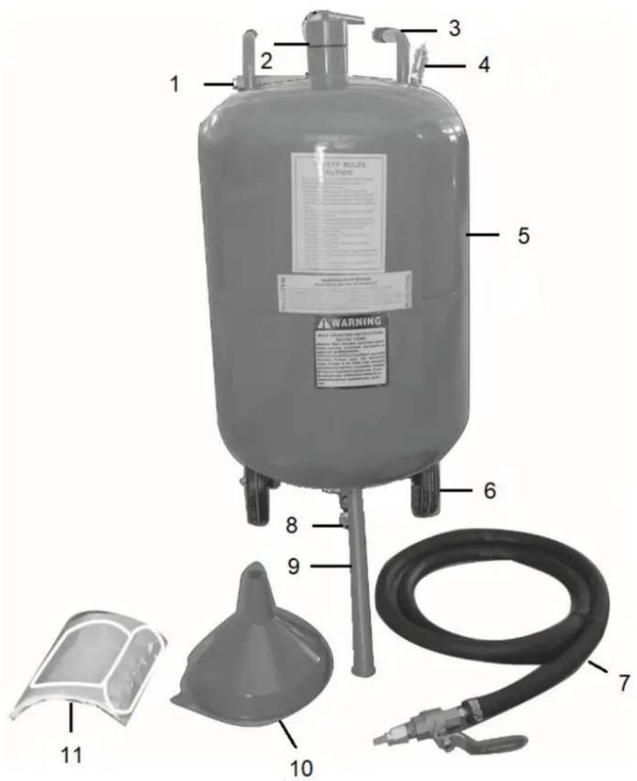
| Number | Description |
| 1 | Connector to the air supply line |
| 2 | Where you pour sand in |
| 3 | Transport grip |
| 4 | Safety valve |
| 5 | Tank |
| 6 | Wheels |
| 7 | Sandblasting hose |
| 8 | Connector to sandblasting hose |
| 9 | Support |
| 10 | Funnel |
| 11 | Head protector |
The detailed product description is as follows:
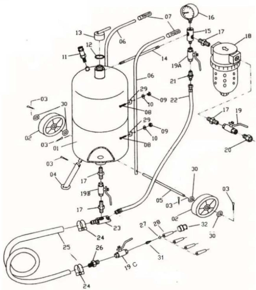
| Number | Description |
| 1 | Tank |
| 2 | Wheel |
| 3 | Fastener |
| 4 | Support |
| 5 | Wheel axle |
| 6 | Transport grip |
| 7 | Grip handle |
| 8 | Screw |
| 9 | Nut |
| 10 | Washer |
| 11 | Safety valve |
| 12 | Gasket |
| 13 | Closure for sand pouring |
| 14 | Tube |
| 15 | Three-way adapter |
| 16 | Manometer |
| 17 | Two-sided nipple |
| 18 | Air dehumidifier |
| 19 | Main air valve 3/8" |
| 20 | Male-female connector |
| 21 | Two-sided nipple |
| 22 | Air hose |
| 23 | Sand outlet pipe |
| 24 | Clamping band |
| 25 | Sandblasting line |
| 26 | Nipple |
| 27 | Gasket |
| 28 | Ceramic nozzle |
| 29 | Grip for fastening handle |
| 30 | Washer |
| 31 | Coupler |
| 32 | Nut fixing nozzle |
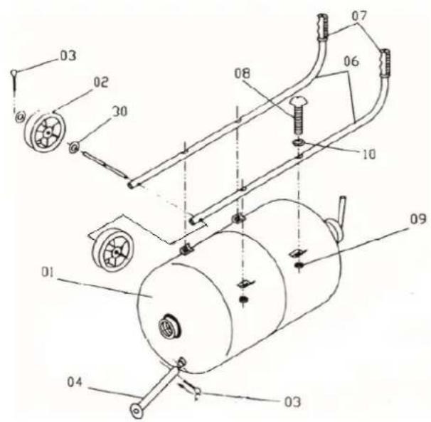
4.2. Preparing for use
Lay the sandblaster tank horizontally, mount the transport grips, the support and the wheels in the manner shown in the figure below. The parts are described in the previous point.
Connect the sandblasting line by fixing it to the sand outlet pipe using a clamping band.
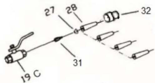
Mounting the nozzle:
Mount the selected nozzle according to the figure below.
Before connecting the compressed air line, it is always necessary to make sure that the main air valve is in the closed position. Connect the compressed air supply line to the male-female coupler (20). Make sure that it is correctly mounted and it will not unfasten under influence of pressure of the compressed air. In order to remove moisture that can cause problems in the operation of the device, the air is dried by a dehumidifier.
The minimum cross-section of the air supply line is 12 ". Using a line with a smaller cross-section will cause the device malfunctioning. For nozzles with a wider cross-section, it is recommended to use a cable with a larger cross-section.
4.2.1. Emptying the dehumidifier of water
1) Close the main air valve, it is also recommended to empty the tank from the pressure.
2) Press the red lock on the dehumidifier and while holding it, turn the lower part of the dehumidifier to the right.
3) Take out and empty the tank.
4) Mount the dehumidifier tank proceeding in a similar way to the disassembly process.
In order to ensure optimum and correct operation of the device, it is necessary to properly select the compressor's efficiency in relation to air consumption by the receiving devices.
The device should be used at a safe distance from the compressor, in order to prevent so that dust with abrasive materials will not get into it.
4.3. Device use
Note: Use the device only and exclusively in the upright position!
4.3.1. Switching on the device
- Connect the compressed air supply line. Set the preferred working pressure on the compressor which will not exceed the maximum value for the device.
• Pour the sand into the tank. - Set the main 3/8 "air valve (19) in the open position - used to regulate the air flow from the compressor to the device.
- Gently open the 3/8 "throttle valve (19a) - used to adjust the flow of the air that draws the sand from the sand outlet pipe towards the nozzle.
• Note: Only and exclusively use the device in the upright position. - Gently open the tank valve (19b) - a valve that regulates the amount of sand getting out from the tank to the sand outlet pipe.
- Set the sandblasting line valve (19c) in the open position - a valve that regulates the flow of the air with sand through the nozzle.
- Open the 3/8 "throttle valve (19a) until the sand appears in the air getting out from the nozzle.
- Set the preferred settings.
- It is recommended to check the operation of the device on a small area in order to check the material reaction to sandblasting.
4.3.2. Lowering the air pressure in the tank
Put on personal protective equipment i.e. upper respiratory protection, safety glasses and gloves.
• Verify whether the main air valve is in the closed position.
- Set the sandblasting line valve in the open position, wait until the "0" value appears on the manometer
4.3.3. Pouring sand into the tank
- Make sure that the sandblasting sand is not moist and will not cause blocking the tank valve, sand outlet pipe, sandblasting line, sandblasting line valve and nozzle and other device components.
- Put on personal protective equipment i.e. upper respiratory protection, safety glasses and gloves.
• Lower the air pressure in the tank. - Unscrew the closure of sand pouring point. Put the funnel with strainer in the hole, and then pour in the appropriate quantity of sand. Note: Do not use the funnel without a strainer. There may be larger lumps in the sand that may cause failure of the device. NOTE: Do not exceed the filling of ca. 34 of the total tank capacity. In case of high ambient humidity, it is not recommended to fill the tank to the maximum, it is necessary to pour smaller portions of sand into the tank and to gradually fill up the tank.
- Remove the funnel. Tighten the closure.
- Close the sandblasting line valve, open the air valve and verify whether the sand pouring point is properly tightened and whether there are no air leaks.
Sandblasting materials often highly absorb water, therefore leaving of unused sand in the tank can cause soaking of the sand, and consequently blocking of the outlets of the device, nozzles, etc.
In the machine it must be used the abrasive material with graininess: 0,2 ÷ 0,7 mm.
The use of the following abrasive materials is permitted:
- Quartz abradant / sand
- Aloxite
- Cast iron shot
- Cast steel shot
- Glass microspheres
- Silicon carbide
In order to achieve the best performance, it is recommended to use the device with an operating pressure between 4.5 and 7.5 Bar.
In case of exceeding the maximum working pressure the safety valve should work.
4.4. Cleaning and maintenance
4.4.1. General instructions
a) Before starting to clean the device it is necessary to disconnect it from the source of the compressed air supply and then to reduce the pressure in the sand tank by releasing the air from it.
b) After finishing each work with the device, it is necessary to clean it thoroughly.
c) Systematically check the condition of nozzles, valves and hoses. The abrasive material causes attrition of the hose walls.
d) Systematically empty the dehumidifier from the water filtered out from the air.
e) Use cleaners without corrosive substances to clean each surface.
f) Dry all parts well after cleaning before the device is used again.
g) Store the unit in a dry, cool place, free from moisture and direct exposure to sunlight.
4.4.2. Disposing of used devices
Do not dispose of this device in municipal waste systems. Hand it over to an electric and electrical device recycling and collection point. Check the symbol on the product, instruction manual and packaging. The plastics used to construct the device can be recycled in accordance with their markings. By choosing to recycle you are making a significant contribution to the protection of our environment.
Contact local authorities for information on your local recycling facility.

| Tall | Beskrivelse |
| 1 | Tank |
| 2 | Hjul |
| 3 | Festemiddel |
| 4 | Støtte |
| 5 | Hjulaksel |
| 6 | Transportgrep |
| 7 | Griphåndtak |
| 8 | Skru |
| 9 | Nøtt |
| 10 | Vaskemaskin |
| 11 | Sikkerhetsventil |
| 12 | Pakning |
| 13 | Lukking for sandhelling |
| 14 | Rør |
| 15 | Treveisadapter |
| 16 | Manometer |
| 17 | Tosidig brystvorte |
| 18 | Luftavfukter |
| 19 | Hovedluftventil 3/8" |
| 20 | Hann-hunn-kontakt |
| 21 | Tosidig brystvorte |
| 22 | Luftslange |
| 23 | Sandutløpsrør |
| 24 | Klemmebånd |
| 25 | Sandblåsingslinje |
| 26 | Brystvorte |
| 27 | Pakning |
| 28 | Keramisk dyse |
| 29 | Grep for feste av håndtaket |
| 30 | Vaskemaskin |
| 31 | Kopling |
| 32 | Mutterfestedyse |
Koble sandblåsingsledningen til sandutløpsrøret med et klemmebånd.
Montering av dysen:
| Broj | Opis |
| 1 | Tenk |
| 2 | Kotač |
| 3 | Zatvarač |
| 4 | Podrška |
| 5 | Osovina kotača |
| 6 | Transportni hvat |
| 7 | Ručka za hvatanje |
| 8 | Vijak |
| 9 | Orah |
| 10 | Perilica rublja |
| 11 | Sigurnosni ventil |
| 12 | Brtva |
| 13 | Zatvaranje za sipanje pijeska |
| 14 | Cijev |
| 15 | Trostruki adapter |
| 16 | Manometar |
| 17 | Dvostrana bradavica |
| 18 godina | Odvlaživač zraka |
| 19 | Glavni zračni ventil 3/8" |
| 20 | Muško-ženski konektor |
| 21 | Dvostrana bradavica |
| 22 | Zračno crijevo |
| 23 | Cijev za izlaz pijeska |
| 24 | Stezna traka |
| 25 | Linija za pjeskarenje |
| 26 | Bradavica |
| 27 | Brtva |
| 28 | Keramička mlaznica |
| 29 | Rukohvat za pričvrš čivanje ručke |
| 30 | Perilica rublja |
| 31 | Spojnica |
| 32 | Mlaznica za pričvrš čivanje matice |
4.2. Priprema za upotrebu
| Številka | Opis |
| 1 | Rezervoar |
| 2 | Kolo |
| 3 | Pritrdilni element |
| 4 | Podpora |
| 5 | Os kolesa |
| 6 | Prijem za prevoz |
| 7 | Ročaj za prijemanje |
| 8 | Vijak |
| 9 | Oreček |
| 10 | Pralni stroj |
For the disposal of the device please consider and act according to the national and local rules and regulations.
CONTACT
expondo Polska sp. z o.o. sp. k.