
HD BoreScope-DuoCamera - Video camera Laserliner - Free user manual and instructions
Find the device manual for free HD BoreScope-DuoCamera Laserliner in PDF.

| Brand | Laserliner |
| Model | HD BoreScope-DuoCamera |
| Product type | Endoscopic video camera (camera unit for VideoFlex HD) |
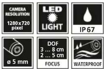
| Camera head diameter | 5 mm |
| Camera resolution | 1280 x 720 pixels |
| Field of view (FOV) | 80° |
| Depth of field (DOF) | Front: 3 to 8 cm / Lateral: 2 to 5 cm |
| Number of LED bulbs | Front: 6 / Lateral: 1 |
| Probe protection type | IP 67 |
| Probe diameter | 5 mm |
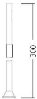
| Probe length | 300 mm |
| Power supply | Via the VideoFlex HD base unit |
| Dimensions (L x H x D) | 450 mm x 30 mm x 30 mm |
| Weight | 235 g |
| Operating conditions | 0°C to 50°C, max. relative humidity 80% (non-condensing) |
| Storage conditions | -10°C to 70°C, max. relative humidity 80% (non-condensing) |
| Max operating altitude | 2000 m above sea level |
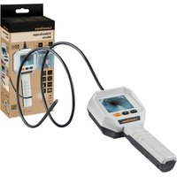
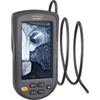
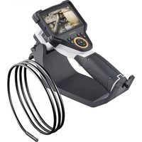
| Main functions | Inspection of cavities, shafts, masonry, vehicles; switching between front and lateral camera; transmission of color images to LCD screen |
| Included accessories | Magnet, mirror, hook |
| Oil and gasoline resistance | Yes |
| Maintenance and cleaning | Clean with a slightly damp cloth; avoid cleaning agents, solvents, and abrasive cleaners; store in a dry, clean place |
| Safety | Do not use for medical examinations; avoid contact with chemicals, electrical voltage, hot or moving parts; do not expose to mechanical loads, extreme temperatures or vibrations; camera head is not resistant to acids or fire |
| Spare parts and repairability | Accessories (magnet, mirror, hook) available; for repair, contact customer service |
| General information | CE and UKCA certified; recycling in accordance with WEEE directives |
Frequently Asked Questions - HD BoreScope-DuoCamera Laserliner
User questions about HD BoreScope-DuoCamera Laserliner
0 question about this device. Answer the ones you know or ask your own.
Ask a new question about this device
Download the instructions for your Video camera in PDF format for free! Find your manual HD BoreScope-DuoCamera - Laserliner and take your electronic device back in hand. On this page are published all the documents necessary for the use of your device. HD BoreScope-DuoCamera by Laserliner.
USER MANUAL HD BoreScope-DuoCamera Laserliner
natural_image
Close-up of a black handheld probe with coiled spring and probe tip, no visible text or symbols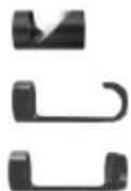
Laserliner
!
Completely read through the operating instructions, the „Warranty and Additional Information” booklet as well as the latest information under the internet link at the end of these instructions. Follow the instructions they contain. These documents must be kept in a safe place and passed on together with the device.
Intended use
The HD BoreScope-DuoCamera is a camera unit for connection to the base VideoFlex HD unit. When combined with the base unit, colour video images are sent to the LCD for inspecting highly inaccessible locations such as cavities, shafts, masonry or in vehicles.
General safety instructions
- The device must only be used in accordance with its intended purpose and within the scope of the specifications.
- This product and its accessories are not toys. Keep out of reach of children.
– The camera head can heat up considerably during use and lead to damage to sensitive inspection objects. - The structure of the device must not be modified in any way.
- Do not expose the device to mechanical stress, extreme temperatures or significant vibration.
- The device must no longer be used if one or more of its functions fails, or if the housing or connecting cables are damaged or the battery charge in the base unit is low.
– The camera head is not acid-resistant or fireproof. - It is absolutely vital to ensure that the HD BoreScope-DuoCamera does not come into contact with chemicals, voltage, moving or hot objects. This can damage the device and put its user at risk of serious injury.
- To preserve the IP 67 rating, the camera probe may only be immersed up to a distance 10cm from the handle.
- The HD BoreScope-DuoCamera must not be used for medical examinations / examining people.
- Please ensure compliance with the safety regulations set out by local and national authorities with regard to the correct and proper use of the device.
- The unit is not suitable for taking measurements close to dangerous voltages. Therefore always make sure that conductive parts are at zero potential when carrying out measurements in the vicinity of electrical systems. Safe isolation from the power supply and precautions to prevent systems being switched on again must be ensured by implementing suitable measures.
Safety instructions
Using artificial, optical emission (OStrV)
LED outlet

- The device works with LEDs of risk group RG 0 (exempt, no risk) in accordance with the latest versions of applicable standards relating to photobiological safety (EN 62471:2008-09ff / IEC/TR 62471:2006-07ff).
- When used for the intended purpose and under reasonably foreseeable conditions, the accessible radiation of the LEDs is safe for the human eye and skin.
Laserliner
Safety instructions
Dealing with electromagnetic radiation
- The measuring device complies with electromagnetic compatibility regulations and limit values in accordance with EMC-Directive 2014/30/EU.
- Local operating restrictions – for example, in hospitals, aircraft, petrol stations or in the vicinity of people with pacemakers – may apply. Electronic devices can potentially cause hazards or interference or be subject to hazards or interference.
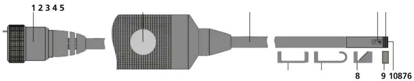
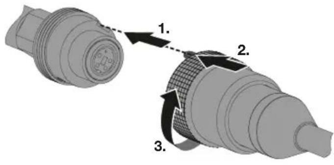
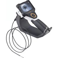
1 Base unit connection
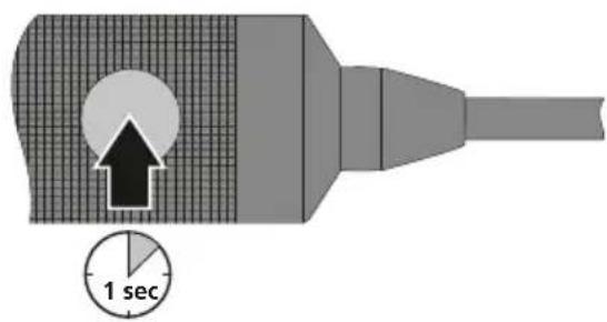
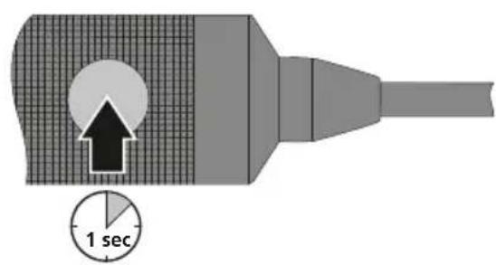
2 Switch between front and side camera
3 Camera probe
4 Side camera
5 Connection magnet/mirror/hook tool
6 Magnet
7 Hook
8 Mirror
9 Thread protector
10 Front camera
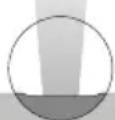
1 Focal depth
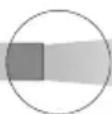
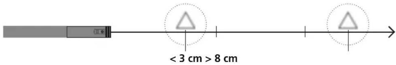
The front camera on the HD BoreScope-DuoCamera delivers sharp images in a range between 3 and 8 cm from the camera head. The side camera has a depth of field of 2 to 5 cm from the camera head.
Front camera illustration
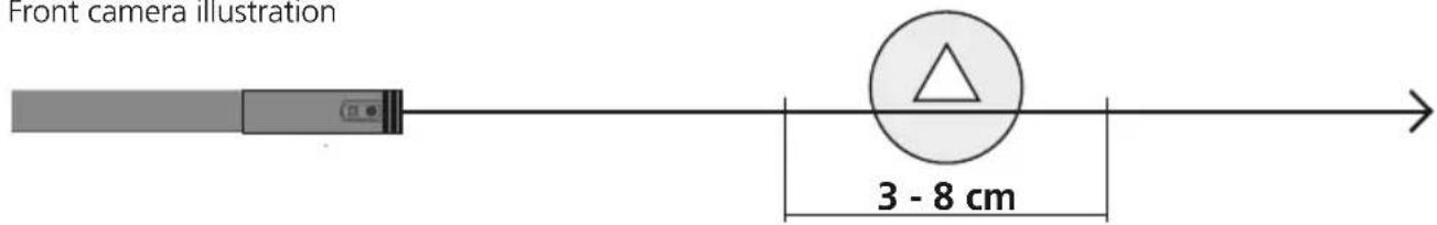
Objects well beyond the focus range may appear blurred.
2 Connection for camera unit
3 Switch between front and side camera

Information on maintenance and care
Clean all components with a damp cloth and do not use cleaning agents, scouring agents and solvents. Store the device in a clean and dry place.
Technical data
Subject to technical alterations. 24W07
| Camera head diameter 5 mm | |
| Camera probe protection class IP 67 | |
| Number of LED lights Front: 6 / Side: 1 | |
| Camera resolution 1280 x 720 Pixel | |
| Field of view (FOV) 80° | |
| Depth of focus (DOF) Front: 3 ... 8 cm / Side: 2 ... 5 cm | |
| Probe diameter 5 mm | |
| Probe length 300 mm | |
| Features | Resistant to oil and petrol accessories included: Magnet, hook, mirror |
| Operating conditions | 0°C ... 50°C, max. humidity 80% rH, no condensation, max. working altitude 2000 m above sea level |
| Storage conditions -10°C ... 70°C, | max. humidity 80% rH, no condensation |
| Weight 235 g | |
| Dimensions (W x H x D) 450 mm x | 30 mm x 30 mm |
EU and UK directives and disposal
This device complies with all necessary standards for the free movement of goods within the EU and the UK.
This product, including accessories and packaging, is an electrical appliance that must be recycled in an environmentally appropriate manner in accordance with European and UK directives on waste electrical and electronic equipment, batteries and packaging, in order to recover valuable raw materials. Electrical devices and packaging do not belong in household waste. Look for information on local disposal facilities and note the relevant disposal and safety information at the collection points.
Further safety and supplementary notices at: https://packd.li/ll/AOJ/in
Laserliner
!
3 Omschakeling frontcamera en camera opzij
https://packd.li/ll/AOJ/in
Laserliner
!
https://packd.li/ll/AOJ/in
Laserliner
!
https://packd.li/ll/AOJ/in
!
https://packd.li/ll/AOJ/in
Laserliner
!
https://packd.li/ll/AOJ/in
!
3 Omkobling front- og sidekamera

https://packd.li/ll/AOJ/in
!
https://packd.li/ll/AOJ/in
Laserliner
!
https://packd.li/ll/AOJ/in
Laserliner
!
https://packd.li/ll/AOJ/in
!
https://packd.li/ll/AOJ/in
Laserliner
!
3 Prebacivanje prednje i bočne kamere

https://packd.li/ll/AOJ/in
!
はじめに
3 フロント/ サイドカメラの切 替
メンテナンスとお手入れについて
仕様
Subject to technical alterations. 24W07
Brand : Laserliner
Model : HD BoreScope-DuoCamera
Category : Video camera