USER MANUAL SC480 DOMETIC
© 2023 Domatic Group. The visual appearance of the contents of this manual is protected by copyright and design law. The underlying technical design and the products contained herein may be protected by design, patent or pending patent. The trademarks mentioned in this manual belong to Domatic Sweden AB. All rights are reserved.
English
1 Important notes. 3 2 Explanation of symbols. 3 3 General safety instructions 4 4 Target Group. 7 5 Scope of delivery. 7 6 Accessories. 7 7 Intended use. 7 8 Technical description. 8 9 Installation. 12 10 Operation 19 11 Cleaning and maintenance. 20 12 Troubleshooting 21 13 Disposal 22 14 Warranty. 23 15 Technical data. 23
1 Important notes
Please read these instructions carefully and follow all instructions, guidelines, and warnings included in this product manual in order to ensure that you install, use, and maintain the product properly at all times. These instructions MUST stay with this product.
By using the product, you hereby confirm that you have read all instructions, guidelines, and warnings carefully and that you understand and agree to abide by the terms and conditions as set forth herein. You agree to use this product only for the intended purpose and application and in accordance with the instructions, guidelines, and warnings as set forth in this product manual as well as in accordance with all applicable laws and regulations. A failure to read and follow the instructions and warnings set forth herein may result in an injury to yourself and others, damage to your product or damage to other property in the vicinity. This product manual, including the instructions, guidelines, and warnings, and related documentation, may be subject to changes and updates. For up-to-date product information, please visit documents.dometic.com.
2 Explanation of symbols

DANGER!
Indicates a hazardous situation that, if not avoided, will result in death or serious injury.

WARNING!
Indicates a hazardous situation that, if not avoided, could result in death or serious injury.

CAUTION!
Indicates a hazardous situation that, if not avoided, could result in minor or moderate injury.

NOTICE!
Indicates a situation that, if not avoided, can result in property damage.
3 General safety instructions
Also observe the safety instructions and stipulations issued by the vehicle manufacturer and authorized workshops.

WARNING! Electrocution hazard
- Installation and removal of the device may only be carried out by qualified personnel.
- Do not operate the device if it is visibly damaged.
- If this device's power cable is damaged, the power cable must be replaced in order to prevent safety hazards.
- This device may only be repaired by qualified personnel. Improper repairs can lead to considerable hazards.
- If you disassemble the device: Detach all connections. Ensure that no voltage is present on any of the inputs and outputs.
- Do not use the device in wet conditions or submerge in any liquid. Store in a dry place.
- Only use accessories that are recommended by the manufacturer.
- Do not modify or adapt any of the components in any way.
- Disconnect the device from the power supply:
Before each cleaning and maintenance
After use
Before changing a fuse
Before carrying out electrical welding work or work on the electrical system

WARNING! Health hazard
- This device can be used by children aged from 8 years and above and persons with reduced physical, sensory or mental capabilities or lack of experience and knowledge if they have been given supervision or instruction concerning use of the device in a safe way and understand the hazards involved.
- Electrical devices are not toys. Always keep and use the device out of the reach of very young children. Children must be supervised to ensure that they do not play with the device.
- Cleaning and user maintenance shall not be made by children without supervision.

NOTICE! Damage hazard
- Before start-up, check that the voltage specification on the data plate is the same as that of the power supply.
- Ensure that other objects cannot cause a short circuit at the contacts of the device.
- Ensure that the negative and positive poles never come into contact.
3.1 Installing the device safely

DANGER! Explosion hazard
Never mount the device in areas where there is a risk of gas or dust explosion.

WARNING! Risk of injury
- The device must be mounted and fastened in such a way that it cannot fall down.
- When positioning the device, ensure that all cables are suitably secured to avoid any form of trip hazard.

NOTICE! Damage hazard
- Do not place the device near heat sources (heaters, direct sunlight, gas ovens, etc.).
- Mount the device in a dry location where it is protected against splashing water.
3.2 Safety when connecting the device electrically

DANGER! Electrocution hazard
If you are working on electrical systems, ensure that there is somebody close at hand who can help you in emergencies.

WARNING! Electrocution hazard
- Observe the recommended cable cross-sections.
- Lay the cables so that they cannot be damaged by the doors or the hood. Crushed cables can lead to serious injury.

NOTICE! Damage hazard
- Use ductwork or cable ducts if it is necessary to lay cables through metal panels or other panels with sharp edges.
- Do not lay the cable so that it is loose or heavily kinked.
- Fasten the cables securely.
- Do not pull on the cables.
3.3 Operating the device safely

WARNING! Explosion hazard
- Only use the device in closed, well-ventilated rooms.
- Do not operate the device under the following conditions:
In salty, wet or damp environments
In the vicinity of corrosive fumes
In the vicinity of combustible materials
In areas where there is a danger of explosions

WARNING! Electrocution hazard
- Observe that parts of the device may still conduct voltage even if the fuse has blown.
- Do not disconnect any cables when the device is still in use.

NOTICE! Damage hazard
- Ensure that the air inlets and outlets of the device are not covered.
- Ensure good ventilation.
- The device shall not be exposed to rain.
3.4 Safety precautions when handling batteries

WARNING! Risk of injury
- Batteries contain aggressive and caustic acids. Avoid battery fluid coming into contact with your body. If your skin does come into contact with battery fluid, wash that part of your body thoroughly with water. If you sustain any injuries from acids, contact a doctor immediately.
- When working on batteries, do not wear any metal objects such as watches or rings. Lead acid batteries can cause short circuits that can cause serious injuries.
- Only use insulated tools.
- Wear goggles and protective clothing when working on batteries. Do not touch your eyes when working on batteries.

CAUTION! Explosion hazard
- Never attempt to charge a frozen or defective battery. Place the battery in a frost-free area and wait until the battery has acclimatized to the ambient temperature. Then start the charging process.
- Do not smoke, use an open flame, or cause sparking near the engine or a battery.

NOTICE! Damage hazard
- Only use rechargeable batteries.
- Prevent any metal parts from falling on the battery. This can cause sparks or short-circuit the battery and other electrical parts.
- Ensure that the polarity is correct when connecting the battery.
- Follow the instructions of the battery manufacturer and those of the manufacturer of the system or vehicle in which the battery is used.
- If the battery has to be removed, first disconnect the ground connection. Disconnect all connections and all consumers from the battery before removing it.
- Only store fully charged batteries. Recharge stored batteries regularly.
- Do not carry the battery by its terminals.
Safety precautions when handling lithium batteries

CAUTION! Risk of injury
Only use batteries with integrated battery management system and cell balancing.

NOTICE! Damage hazard
- Only install the battery in environments with an ambient temperature of at least 0°C .
- Avoid deep discharge of the batteries.
Safety precautions when handling lead acid batteries

CAUTION! Health hazard
The water-acid liquid inside the battery can evaporate and cause an acidic odor. Use the battery only in a well-ventilated area.

NOTICE! Damage hazard
- The battery is not sealed. Do not turn the battery on its side or upside down. Place the battery on a horizontal surface.
- Check the acid level for open lead acid batteries regularly.
- Immediately recharge deeply discharged lead acid batteries to avoid sulfation.
4 Target Group

The electrical power supply must be connected by a qualified electrician who has demonstrated skill and knowledge related to the construction and operation of electrical equipment and installations, and who is familiar with the applicable regulations of the country in which the equipment is to be installed and/or used, and has received safety training to identify and avoid the hazards involved.
5 Scope of delivery
| Description Quantity |
| Solar charge controller 1 |
| Temperature sensor 1 |
| Spare fuse (30 A) 1 |
| WAGO connector SC330: 1 |
| SC480: 2 |
| Mounting screw 4 |
| Short operating manual 1 |
| Installation and operating manual (digital only) 1 |
6 Accessories
Description Ref. no.
TD283 touch display 9620013272
7 Intended use
The solar charge controller is intended to ensure the correct charging voltage of the house battery when being charged by solar panels using microprocessor controlled IU0U charging programs and to protect the battery against over voltage and deep discharge.
EN
Additionally the solar charge controller secures a sufficient state of charge of the starting battery to ensure the starting of the engine.
The solar charge controller is only suitable for controlling solar modules.
The solar charge controller is not suitable for controlling other charging sources.
The solar charge controller is intended for charging the following battery types:
- Lead acid batteries
- Lead gel batteries
- Absorbed glass mat (AGM) batteries LiFePO4 batteries
The solar charge controller is not intended for charging other types of batteries (e.g., NiCd, NiMH, etc.).
The solar charge controller is suitable for:
- Installation in recreational vehicles
- Stationary or mobile use
- Indoor use
The solar charge controller is not suitable for:
- Mains operation
- Outdoor use
The energy output of connected solar panels must not exceed the maximum output stated in the technical data.
This product is only suitable for the intended purpose and application in accordance with these instructions.
This manual provides information that is necessary for proper installation and/or operation of the product. Poor installation and/or improper operating or maintenance will result in unsatisfactory performance and a possible failure.
The manufacturer accepts no liability for any injury or damage to the product resulting from:
- Incorrect assembly or connection, including excess voltage
- Incorrect maintenance or use of spare parts other than original spare parts provided by the manufacturer
- Alterations to the product without express permission from the manufacturer
- Use for purposes other than those described in this manual
Dometic reserves the right to change product appearance and product specifications.
8 Technical description
General description
The solar charge controller offers the following functions:
- Microprocessor-controlled, temperature-compensated IUOU charging programs for various battery types Maximum power peak tracking (MPPT)
- Bluetooth connection for data and function display on the mobile app
The solar charge controller has the following protective mechanisms:
High voltage protection
- Low voltage protection High temperature protection
- Low temperature protection (only LiFePO4 batteries with connected temperature sensor)
- Battery overcharge protection (only with connected temperature sensor)
- Reverse current protection
- Short circuit protection
- Reverse polarity protection for solar panel inputs
The temperature sensor monitors the battery temperature during the charging process to control and adjust the charging voltage accordingly.
The solar charge controller can be adapted to different battery types of the house battery via DIP switches.
Optionally the TD283 touch display (accessory) can be connected for displaying external data and the progress of the charging process.
Connections and controls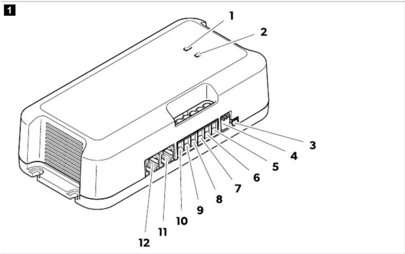
Table 1: Connections and controls
| No. Description |
| 1 Status LED of the house battery (B1) |
| 2 Status LED of the starting battery (B2) |
| 3 Connection to the temperature sensor |
| 4 DIP switches for setting the house battery type |
EN
| No. Description |
| 5 Connection to positive pole of the starting battery |
| 6 Connection to positive pole of the house battery |
| 7 Connection to positive pole of solar panel 1 |
| 8 Connection to positive pole of solar panel 2 |
| 9 Connection to negative pole of the house battery |
| 10 Connection to negative pole of solar panels |
| 11 Connection to TD283 touch display (accessories) or CI-BUS |
| 12 Connection to TD283 touch display (accessories) or CI-BUS |
LED indicators
Table 2: LED indicators
| LED Status Description | | |
| On Batteries fully charged (100%)Green |
| Flashing Charging process |
| Orange Flashing Charging process, voltage < 12 V |
| Red Flashing Error (see chapter Troubleshooting on page 21) |
Battery charging function
A main charging cycle of the house battery is initiated after the house battery voltage has fallen below the reset voltage.
A main charging cycle of the starting battery is initiated in the following events:
After falling below the low reset voltage of the starting battery (charging phase of the house battery is not considered) After falling below the reset voltage of the starting battery when the house battery is in trickle charging phase (Float)
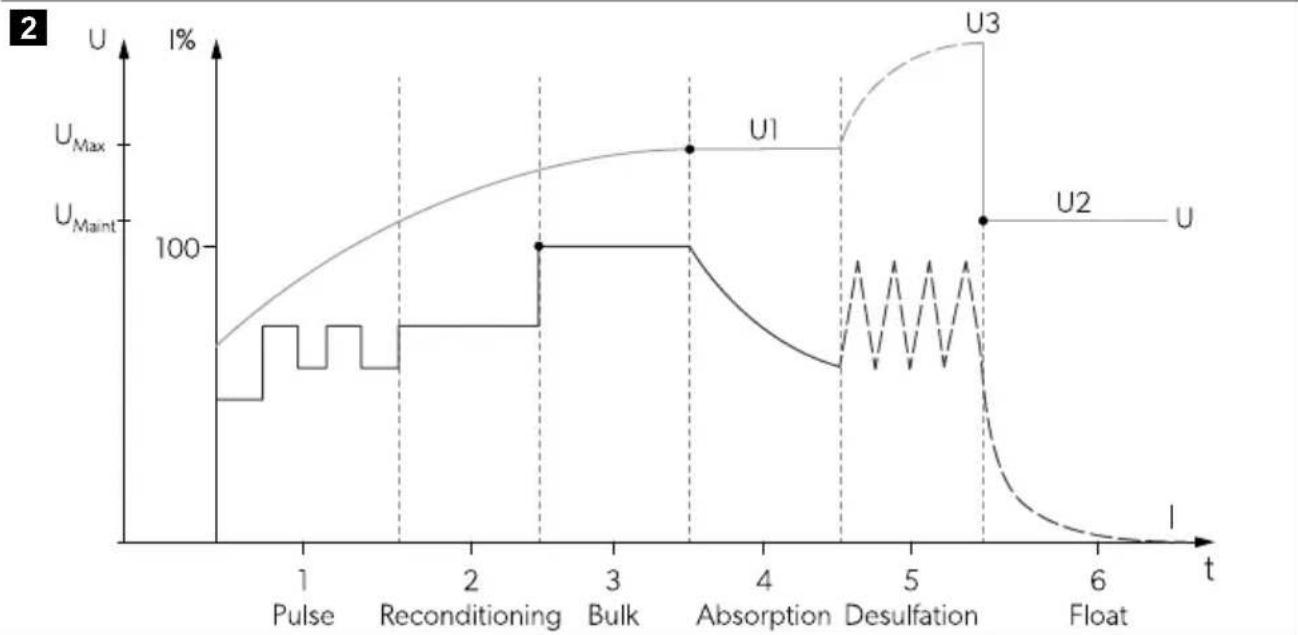
1: Pulse
With a voltage between 8 and 10.5 V, a reduced current will be delivered every 5 s (timeout 4 h).
2: Reconditioning phase
With a voltage between 10.5 V and 12 V, a reduced current will be delivered (timeout 8 h).
3: Constant current phase (Bulk)
House battery (B1): With a voltage between 12 V and U1 (maximum voltage of the selected charging curve), the maximum current will be delivered. The maximum delivered current is dependent on the power of the installed solar panels (Wp) and the solar charge controller used:
SC330:20A SC480:30A
Starting battery (B2): With a voltage between 12 V and 14.2 V, a maximum current of 10 A will be delivered.
4: Constant voltage phase (Absorption)
House battery (B1): With a voltage equal to U1 (maximum voltage of the selected charging curve) a constant voltage equal to U1 will be delivered. The delivered current will decrease as the battery state of charge (SoC) increases. The constant voltage phase is limited depending on the charging program selected (see chapter Setting the charging program on page 19).
Starting battery (B2): A constant voltage of 14.2 V will be delivered for 15 min.
5: Desulfation

NOTE Only for AGM2 batteries if the charging program is selected (see chapter Setting the charging program on page 19).
House battery (B1): The current pulses while the battery voltage rises to U3 to remove sulfate from the lead plates of the battery and restore battery capacity. This phase ends after U3 is reached (timeout 2 h).
6: Trickle charging phase (Float)
House battery (B1): The trickle charging phase keeps a constant voltage (U2) related to the selected charging curve. As soon as the battery voltage has dropped to a certain value, the device re-enters the constant current phase.
Temperature sensor
With the temperature sensor connected, the solar charge controller adapts the charging voltage (for lead batteries) or the charging current (for LiFePO4 batteries) according to the measured temperature at the battery.
For lead batteries: Without the temperature sensor connected or if the temperature sensor is defective, the charging voltage is referenced to 20°C.
For LiFePO4 batteries: Without the temperature sensor connected, the solar charge controller does not work.
9 Installation
Installation location
Observe the following instructions when selecting an installation location:
- Install the device close to the batteries to keep the battery connection cable as short as possible.
- Ensure that the mounting surface is solid and level.
- Choose a location that is well ventilated and protected from moisture and dust.
- Keep a distance of 10 cm to all sides around the device.
Mounting the solar charge controller

NOTICE! Damage hazard
Before drilling any holes, ensure that no electrical cables or other parts of the vehicle can be damaged by drilling, sawing, or filing.
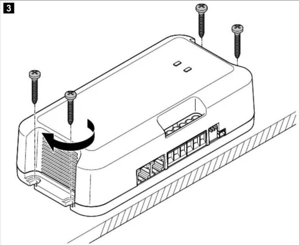
Mount the solar charge controller with the 4 screws provided vertically on a wall with the terminals pointing down.
Connecting the solar charge controller

WARNING! Electrocution hazard
- Completely cover all solar panels with an opaque material during installation to prevent electricity from being generated.
- Observe the recommended cable cross sections, cable lengths, and fuse.

CAUTION! Fire hazard
Place the fuses near the batteries to protect the cables from short circuits and possible burning.

NOTICE! Damage hazard
- Do not reverse the polarity.
- Do not connect the negative terminal of the solar panel to ground (chassis). Always use the solar charge controller terminal for connection to the negative pole of solar panels.
Observe the following instructions when connecting the solar charge controller:
- Connect the house battery before connecting the solar panels.
- Do not use ferrules. Strip the cable ends at 10 mm.
- Connect several solar panels only in parallel and up to the rated power of the solar charge controller.
- In the case of two or more batteries, parallel connection is permissible if the batteries are of the same type, capacity, and age. Connect the batteries diagonally.
- To ensure measuring the internal temperature of the battery, connect the temperature sensor provided to the negative terminal of the house battery.
- Use suitable measuring instruments:
Multimeter with DC voltage measurement, 200 V or autoscale
Amperometric clamp with direct measurement (100 A scale or higher)
Connection variant A (SC330 only)
Connection variant for solar panel outputs up to 240 Wp
To connect the solar charge controller, proceed as shown in Fig. 4 on page 14.
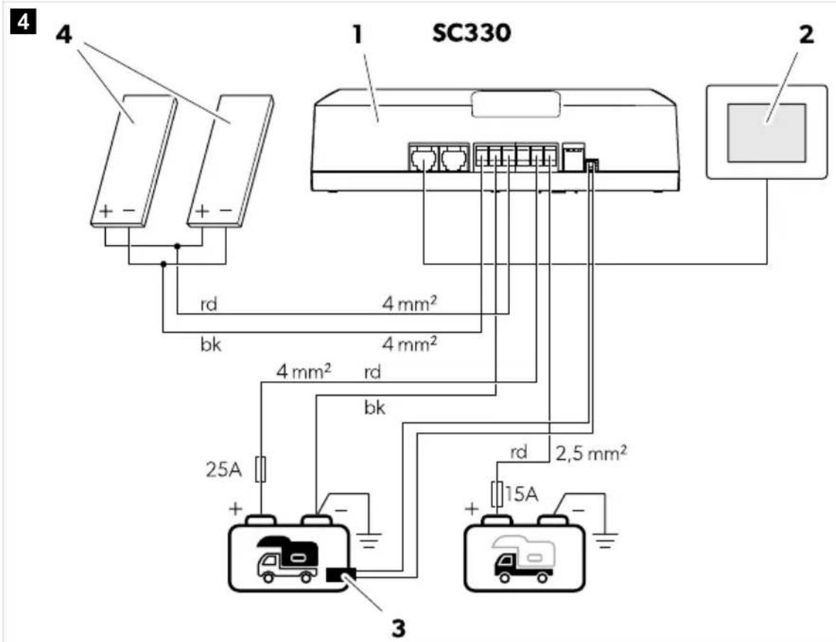
Table 3: Connection diagram SC330
| No. Description | |
| 1 Solar charge controller | |
| 2 TD283 touch display (accessory) | |
| 3 Temperature sensor | |
| 4 Solar panel(s) | |
| House battery |
Table 4: Color coding
| No. Description | |
| Starting battery (optional) |
| Code Colour | |
| rd red | |
| bk black | |
Connection variant B (SC330 only)
Connection variant for solar panel outputs up to 240 Wp
To connect the solar charge controller, proceed as shown in Fig. 5 on page 15.
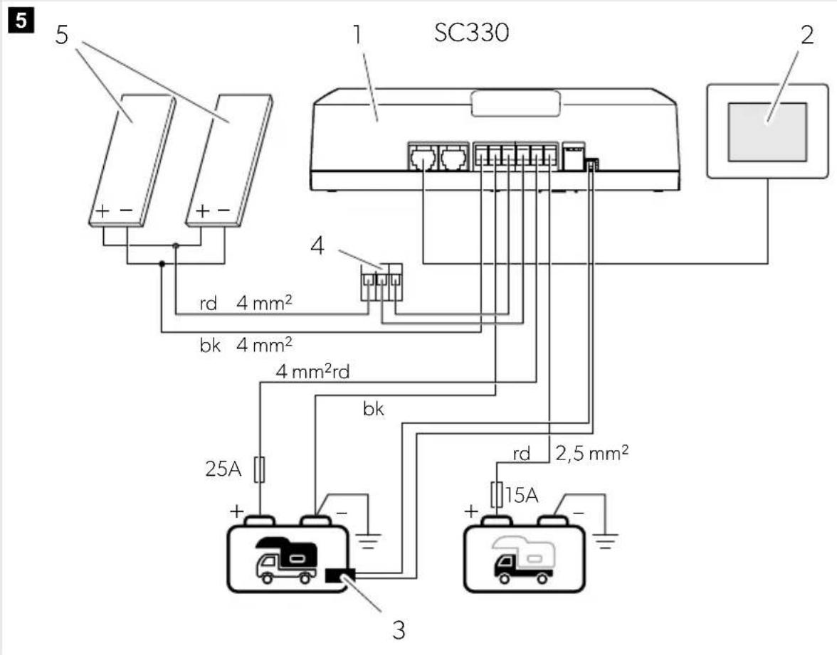
Table 5: Connection diagram SC330
| No. Description | |
| 1 Solar charge controller | |
| 2 TD283 touch display (accessory) | |
| No. Description | |
| 3 Temperature sensor | |
| 4 WAGO connector | |
| 5 Solar panel(s) | |
| House battery |
| Starting battery (optional) |
Table 6: Color coding
| Code Colour | |
| rd red | |
| bk black | |
Connection variant C (SC480 only)
To connect the solar charge controller proceed as shown in Fig. 6 on page 16.
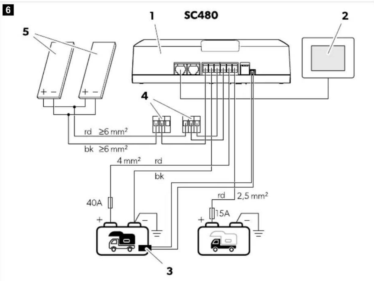
Table 7: Connection diagram SC480
| No. Description | |
| 1 Solar charge controller | |
| 2 TD283 touch display (accessory) | |
| 3 Temperature sensor | |
| 4 WAGO connector | |
| 5 Solar panel(s) | |
| House battery |
| Starting battery (optional) |
Table 8: Color coding
| Code Colour | |
| rd red | |
| bk black | |
Connection variant D (SC480 only)
To connect the solar charge controller proceed as shown in Fig. 7 on page 18.
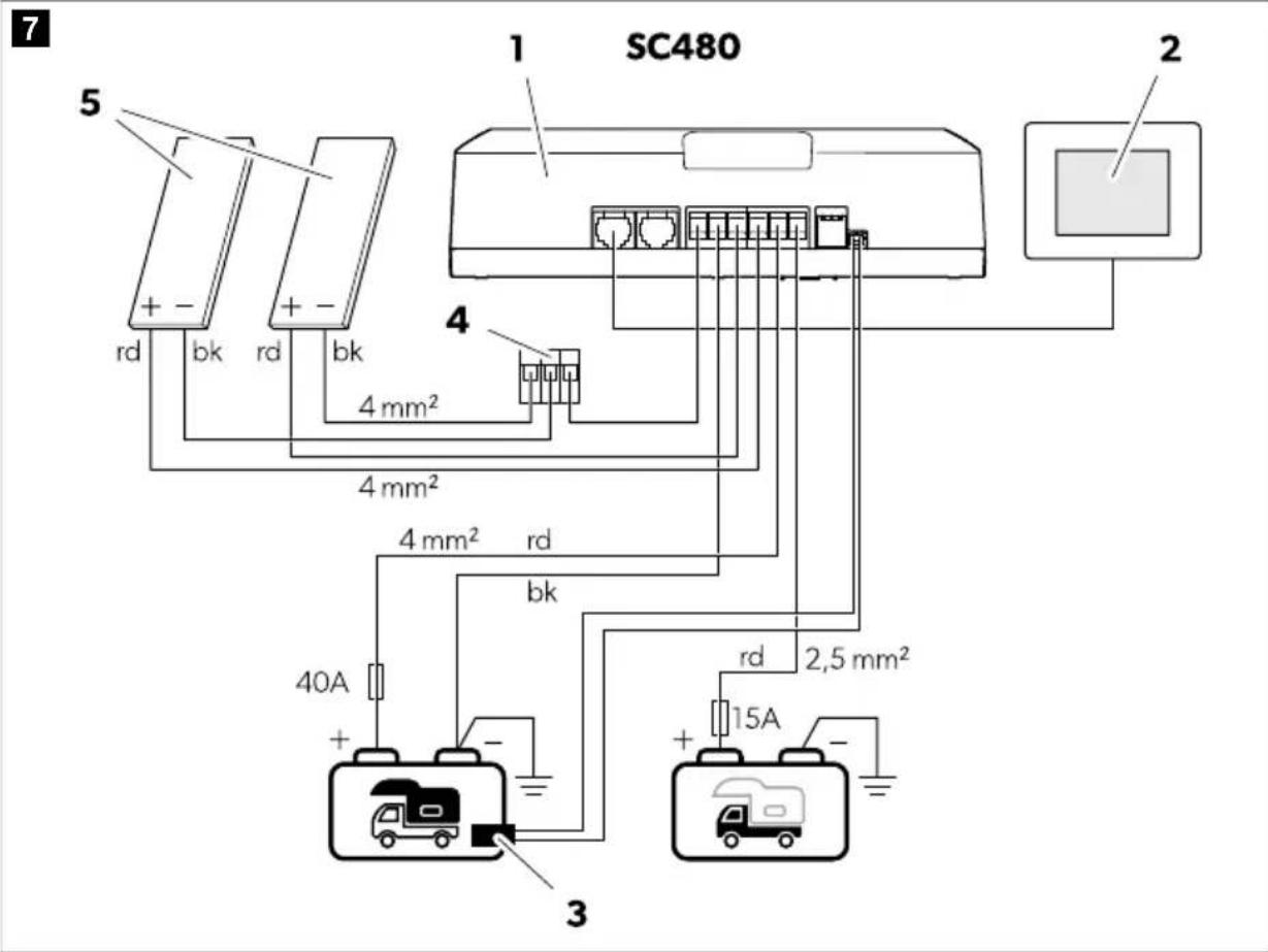
Table 9: Connection diagram SC480
| No. Description | |
| 1 Solar charge controller | |
| 2 TD283 touch display (accessory) | |
| 3 Temperature sensor | |
| 4 WAGO connector | |
| 5 Solar panel(s) | |
| House battery |
| Starting battery (optional) |
Table 10: Color coding
| Code Colour | |
| rd red | |
| bk black | |
10 Operation
Setting the charging program

NOTICE! Damage hazard
- Only use batteries that are suitable for the specified charging voltage.
- Use a small screwdriver to carefully move the DIP switches to the required position.
Select the charging program suitable for the type of house battery used based on the battery manufacturer's specifications, the information on the charging curves (see chapter Battery charging function on page 10), and the technical data (see chapter Technical data on page 23). The specified charging times apply to an average ambient temperature of 20°C.
Slide the DIP switches to the position shown in the table below to set the charging program for the respective type of house battery.
Table 11: Charging curve configuration
| DIP switch position (gray) | Desired charging program DIP switch position (gray) | Desired charging program |
| 123 ON | Lead gel batteries (14.2 V)
• U1: 14.2 V (90 ... 360 min)
• U2: 13.6 V | LiFePO4 batteries (14.4 V)
• U1: 14.4 V (20 ... 60 min)
• U2: 13.8 V |
| 123 ON | Lead-acid batteries (14.4 V) or AGM1 batteries (14.4 V)
• U1: 14.4 V (30 ... 240 min)
• U2: 13.6 V | LiFePO4 batteries (14.2 V)
• U1: 14.2 V (30 min)
• U2: 13.6 V |
| 123 ON | AGM2 batteries (14.7 V)
• U1: 14.7 V (30 ... 180 min)
• U2: 13.6 V | LiFePO4 batteries (14.6 V)
• U1: 14.6 V (20 ... 60 min)
• U2: 13.8 V |
| 123 ON | AGM2 batteries with desulfation (14.7 V)
• U1: 14.7 V (30 ... 180 min)
• U2: 13.6 V
• U3: 15.7 V | LiFePO4 batteries (14.5 V)
• U1: 14.5 V (30 ... 90 min)
• U2: - |
The solar charge controller regulates the charging of up to two batteries: One house battery (B1) and one starting battery (B2), with priority charging to the house battery.
The house battery will be charged under the following conditions:
- The connected solar panels deliver a voltage >16 V.
- The battery voltage is >8 V.
The house battery will be charged with the selected charging curve (see chapter Setting the charging program on page 19).
The starting battery will be charged under the following conditions:
The house battery is in trickle charging phase (float) and the starting battery has a voltage of < 12.5 V. - The starting battery has a voltage of < 11.9 V for 20 min.
Every charging phase has a maximum run time with the exception of the trickle charging phase (float) that constantly monitors the state of charge (SoC) and, if necessary, delivers an impulse current to keep the battery 100% charged.
- Cover all solar panels with an opaque cloth or material to prevent the production of electricity.
- If installed, turn off and disconnect any other auxiliary power sources (e.g., battery chargers).
- Measure the voltage of the batteries (value 1) with the voltmeter.
- Remove the covering from all solar panels. Ensure direct sunlight for optimal performance of the solar panels.
- Measure the voltage of the batteries (value 2) with the voltmeter. Compare value 2 with value 1 from the previous measurement.
Value 2 should be higher than value 1.
- Check the charging current using the mobile app, an ammeter, or optionally the TD283 touch display (accessory).
Downloading the SunControl app
The solar charge controller can be monitored and controlled via Bluetooth using an app that can be installed on a compatible device.
Download the SunControl app from the App Store or Google Play:

qr.dometic.com/beWnPI.
Note that the SunControl app may not be available in your country.
11 Cleaning and maintenance

NOTICE! Damage hazard
- Never clean the device under running water or in dishwater.
- Do not use sharp or hard objects, abrasive cleaning agents, or bleach during cleaning as these can damage the device.
Occasionally clean the product with a damp cloth.
Regularly check live cables or lines for insulation faults, breaks, or loose connections.
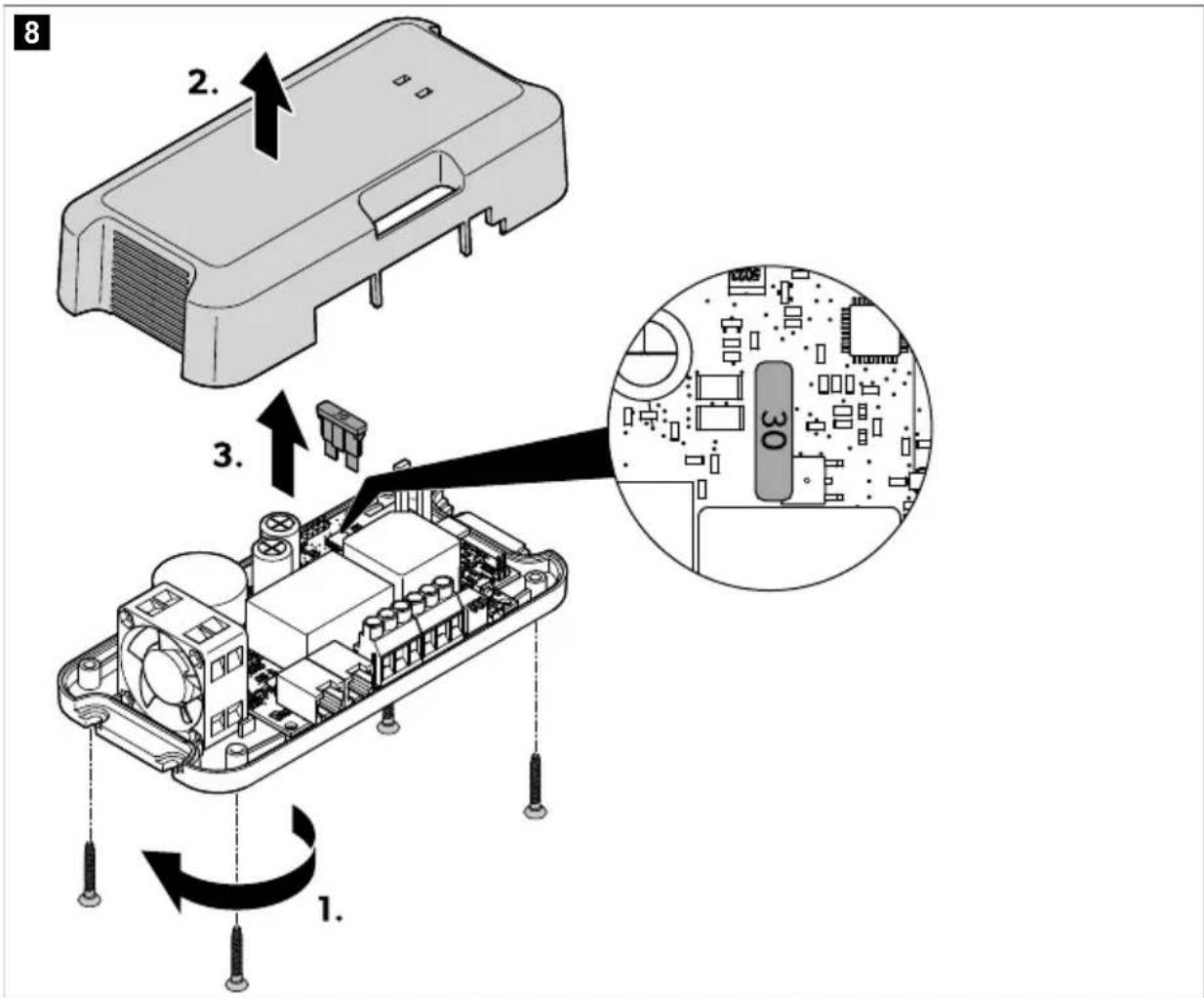
Replacing the fuse

WARNING! Electrocution hazard
The device fuse may only be replaced by qualified personnel.
Replace the fuse as shown in Fig. 8 on page 21. Use the spare fuse provided.
12 Troubleshooting
| Problem Possible cause Suggested remedy |
| The solar charge controller does not work. The LEDs do not light up. | Insulation faults, breaks or loose connections at the live cables. |
|
|
|
|
|
|
EN
| Problem Possible cause Suggested remedy | |
| The solar system does not work properly (low power output). Objects or dirt are blocking out light. | Check for obstructions and ensure that the solar panels are not blocked by shadows.
Move the vehicle to a more suitable location.
Remove any dirt. |
| Overheating of the solar panels. | Allow the solar panels to cool down.
Move the vehicle to a more suitable location.
Ensure sufficient air circulation around the solar panels. |
| One solar panel in the array failed. | Pull out the fuse on the solar charge controller and check the solar panel voltage (VoC) on the solar charge controller.
Check the solar panels for micro cracks.
Check the solar panels for delamination.
Replace the defective solar panel if necessary. |
| Short circuit has been generated. | The device fuse must be replaced after it has been triggered by excess current (see chapter Replacing the fuse on page 21).
Let the fuse be replaced by qualified personnel only. |
| The solar charge controller does not work. The status LED of the house battery (B1) is flashing red. | Only LiFePO4 batteries: Temperature sensor is not connected. | Only LiFePO4 batteries: Connect the temperature sensor. |
| The solar charge controller does not work. The two LEDs (B1 and B2) are flashing red. | The device fuse is defective. | The device fuse must be replaced after it has been triggered by excess current (see chapter Replacing the fuse on page 21).
Let the fuse be replaced by qualified personnel only. |
13 Disposal

Recycling packaging material: Place the packaging material in the appropriate recycling waste bins wherever possible.
Recycling products with non-replaceable batteries, rechargeable batteries or light sources:
- If the product contains any non-replaceable batteries, rechargeable batteries or light sources, you don't have to remove them before disposal.
- If you wish to finally dispose of the product, ask your local recycling center or specialist dealer for details about how to do this in accordance with the applicable disposal regulations.
- The product can be disposed free of charge.
14 Warranty
The statutory warranty period applies. If the product is defective, please contact the manufacturer's branch in your country (see dometic.com/dealer) or your retailer.
For repair and warranty processing, please include the following documents when you send in the device:
A copy of the receipt with purchasing date - A reason for the claim or description of the fault
Note that self-repair or nonprofessional repair can have safety consequences and might void the warranty.
15 Technical data
| SC330 SC480 |
| Maximum solar panel voltage (VoC) 32 V | - |
| Recommended solar panel output 75 ... 330 Wp 110 ... 480 Wp |
| Output house battery (B1) |
| Nominal voltage 12 V | |
| Maximum charging current 20 A 30 A | |
| Minimum battery capacity required | |
| Lead acid 60 Ah 100 Ah | |
| LiFePO4 40 Ah 60 Ah | |
| Minimum battery voltage 8 V | - |
| Temperature regulated charging Up to - | 0.03 V/°C |
| Output starting battery (B2) |
| Nominal voltage 12 V | |
| Maximum charging current | 10 A |
| Minimum battery voltage 8 V | - |
| General technical data |
| Maximum standby current consumption | 0.6 mA |
| Internal fuse | 30 A |
| Ambient temperature for operation | -20 °C ... 50 °C |
| Ambient humidity | 0 90 %, non-condensing |
EN
| SC330 SC480 |
| Dimensions 170 mm × 88 mm × 48 mm | |
| Weight 305 g 345 g | |
| Frequency band (Wi-Fi) 2.4 GHz ISM Band (2400 ... 2484 MHz) |
| RF output power 4 dBm (Bluetooth V5.0 Single Mode LE) |
| Certification | CE UK E24
TGR-06/02 4836 00 |
Hereby, Dometic Mobile Power Italy S.r.l. declares that the radio equipment type SC330 and SC480 are in compliance with Directive 2014/53/EU. The full text of the EU declaration of conformity is available at the following internet address: documents.dometic.com
Deutsch
qr.dometic.com/beWnPI.
8 Description technique
1: pulsation (Pulse)
3: Phase de courant constant (principal)
qr.dometic.com/beWnPl.
qr.dometic.com/beWnPI.
qr.dometic.com/beWnPI.
Scaricare I'app SunControl
qr.dometic.com/beWnPI.
- Lead-acid batteries
- Gel batteries, AGM batteries, LFP batteries
Download the SunControl app
qr.dometic.com/beWnPI.
Note that the SunControl app may not be available in your country.
5: Desulfation

NOTE: Only for AGM2 batteries if the charging program is selected (see chapter Setting the charging program on page 179).
CAUTION! Fire hazard
Place the fuse near the batteries to protect the cables from short circuits and possible fire.

IMPORTANT! Risk of damage
qr.dometic.com/beWnPI.
qr.dometic.com/beWnPI.
The SunControl app may not be available in your country.
Table 105: Color coding
Connection variant C (SC480 only)
Table 109: Color coding
10 Operation
Setting the charging program

CAUTION! Risk of injury
Install the SunControl app
The solar charge controller can be monitored and controlled via Bluetooth using an app that you can install on a compatible device.
Download the SunControl app from the App Store or Google Play.

qr.dometic.com/beWnPI.
qr.dometic.com/beWnPI.
5: Desulphation

qr.dometic.com/beWnPl.
qr.dometic.com/beWnPI.
Please note that the SunControl app may not be available in your country.
11 Cleaning and maintenance

WARNING! Risk of damage
Never clean the device under running water or even in water. - Do not use sharp or hard objects, abrasive cleaning agents or bleach for cleaning, as they could damage the device.
5: Desulfation

NOTE Only for AGM2 batteries. If the charging program is selected (see chapter Setting the charging program on page 312.)
qr.dometic.com/beWnPI.
Please note that the SunControl app may not be available in your country.
11 Cleaning

qr.dometic.com/beWnPI.
gr.dometic.com/beWnPI.
3: Constant current stage (Bulk)
qr.dometic.com/beWnPI.
qr.dometic.com/beWnPI.
The SunControl app may not be available in your country.
qr.dometic.com/beWnPI.
3 O6uHnHCTpyKuH 3a 6e3oNaCHOCT
Cbto taka cna3BaIte HNCTpyKcHnTE 3a 6e3onacHocT nPpeDncaHnra, N3daeHN OT npOn3BOHTeHa npeBo3HOTo CpeCTBO N ynbNHOMOuEHNTE cepBn3N.

PNEyIPEXDEHNE! OnachocTo teneKtpueecknydap
- MoHTnpaHTo I OCTpaHraBaHeTo Ha yCTpoiCTBOTo MOKe Da Ce N3BbPbBa CaMo OT KBaJIINΦnIupaH nepcoHaI.
- He pa6oTeTe cypeJa, aKo e BnIMMo yBpeJeH.
- Ako 3axpaHbuaT KabeH h ToBa yCTpoiCTBO e NobpeDeH, TOn Tp86Ba da 6bde CmeHeH, 3a da ce npedeTbpatn eBentyAnHa onaCHOCT. ToBa yctpoiCTBO Moxe 6bIe peMOHTnpaHO cAmO OT KBAHnΦnIpaH nepcoHAn. HenpaBnHn peMOHTN MORAT Da DOBeDaT DO 3HaunTeHN OnaCHOCTN. Ako pa3rno6BaTe yCTpoiCTBoto: Pa3KaueTe BCnUKN Bpb3Kn. YBepTe ce, ye Hma HanpeXeHne B KOI TO N Da e OT BXOIOBete N 3XODInTe.
- He n3no3BaIte yCTpoiCtBoto npu MOKpn ycNoBn I He rO notaTne B TeUHocT. CbXpaHraBaIte Ha cyxo MRCTO.
- N3non3BaIte cAmO akcecoapn, npenopbuaHn ot npon3BouTeTne. He MoIeHnIe HnHaIeHTpe HNKOIOT KOMNoHEHTe NO KaKbBTo I Da e HaunH.
- 13KIOUeTe yCTPOIcTBOTO t3XpaHBAHeTo:
PpeINBCaKo nouchTbaHe nnoDpBxKa
Cneynotpe6a
PpeiCmHaHa nppeDnA3nten
Ipei n3BbprBaHe Ha eNeKtpnueckn 3abapbHn pa6OTn nn pa6Ota no eNeKtpnueckata cnCTema

IPEyIeHHe! Onachoc 3a 4paBeTo
To3n ypeM MoKe Da Ce H3NON3Ba OTe Da Ha Bb3pact 8 n NobeYe rOdnHn nIuca C HamaNeHn pN3NuEcK, ceH3OpHN IIN YMCtBeHn CnOCo6HocTN, INn C IINcHa 3HaHn r ONIT, AKO NOnyuaBAt Ha3Op INn IHCTpykUnn OTHOCHO H3NON3BaHeTO Ha ycTpoiCtBOTo NO 6e3OnaceH hauHn pa36npaT Cbbp3aHnte C Heo OnaCHOCTN. -Enektpnuecknte ypeHn He ca netcKa nrpauka! BnHaRn cbxpaHraBaIte Nn3non3BaIte yctpoiCTBOTO daJeU OT Docera Ha MHOrO MaKNu Deua. - Deua trpa6Ba da ca na Hb6nOdeHne, 3a da e cnpyHo, Ye He cn nIrpAraT cypea. - NocntBaHe n noDpBka He Tpa6Ba Da ce n3BbPbBa Oeua 6e3 Ha6nIOHeHne.

WARNING! Risk of damage
- Install the device in accordance with the voltage on the plate with the data, as well as the protection. - Make sure that the objects cannot be connected at the contacts of the device. - Make sure that the negative and positive poles do not come into contact.
3.1 Safe installation of the device

DANGER! DANGER OF EXPLOSION
Never install the device in places where there is a risk of explosive gas or dust.

WARNING! RISK OF DAMAGE
- The device must be installed and secured so that it cannot fall.
- When positioning the device, make sure that all cables are properly secured, to avoid any form of danger from tripping.

WARNING! Risk of damage
- Do not install the device near heat sources (heating, open flames, gas burners, etc.).
- Install the device in a dry place, protected from splashes of water.
3.2 Safety during electrical connection of the device

DANGER! Danger of electric shock
If you work on electrical systems, make sure there is someone nearby who can help you in an emergency.

WARNING! Danger of electric shock
Do not bend the power cables. Route the cables so that they cannot be damaged by doors or hatches. A bent cable can lead to serious damage.

WARNING! Risk of injury
- Use pipes or cable ducts if you need to route cables through metal panels or other panels with sharp edges. Do not route cables so that they are loose or excessively taut.
- Secure the cables properly.
- Do not drop the cables.
3.3 Safety during operation of the device

WARNING! Risk of electric shock
- Use the device only in enclosed, well-ventilated rooms.
- Do not operate the device under the following conditions:
In salty, humid, or wet environments, near corrosive substances, near flammable materials, or where there is a risk of explosion.

WARNING! Risk of electric shock
- Be aware that all parts of the device may carry voltage if the device is damaged.
- Do not bend the cables while the device is in use.

WARNING! Risk of injury
- Ensure that the air inlet and outlet openings of the device are not covered.
- Check the ventilation.
- The device does not require any maintenance.
WARNING! Risk of injury
- Mount the battery only in environments with ambient temperature at least 0°C - avoid deep discharge of the batteries.
Precautions when working with lead-acid batteries

WARNING! Health hazard
The acid in the battery can leak and cause acid burns. Use the battery only in a well-ventilated room.

WARNING! Risk of injury
- The battery is not charged. Do not short-circuit the battery with the metal part of the tool. Place the battery on a horizontal surface. - Check the acid level in the battery and the acid density.
- Always dispose of deeply discharged lead-acid batteries properly to avoid sulfation.
Address

The electrical connection must be made by a qualified electrician, connected in accordance with the regulations and the operation of electrical equipment and installations, and who is familiar with the applicable regulations of the country in which the equipment is to be installed and/or used, and has received safety training to identify and avoid the associated hazards.
5 Scope of delivery
The power output of the connected units and antennas cannot reach the maximum power specified in the technical data.
This product is suitable for the intended use and the associated instructions.
This manual provides the information necessary for the correct installation and/or operation of the product. Improper installation or use may lead to unsatisfactory operation and possible damage.
The manufacturer is not responsible for any damage or injury to the product caused by:
- Incorrect installation and connection, including overvoltage.
- Incorrect maintenance or use of spare parts, different from the original ones provided by the manufacturer.
- Modifications to the product without prior written permission from the manufacturer.
- Use for purposes other than those described in this manual.
Dometic reserves the right to change the product specifications.
Technical description
General description
The solar charging device offers the following functions:
- Charging program with microprocessor control and temperature compensation for different types of batteries.
- Tracking of the maximum power point (MPPT).
- Bluetooth connection for displaying data and functions on the mobile app.
The solar charge controller has the following protections:
Protection against overvoltage, protection against undervoltage, protection against high temperature, protection against low temperature (only for LiFePO4 batteries with connected temperature sensor), protection against battery overvoltage (only with connected temperature sensor), protection against reverse current, protection against short circuit, protection against reverse polarity at the solar panel input.
The temperature sensor measures the battery temperature during the charging process to control and regulate the charging voltage accordingly.
The solar charge controller can be connected to various types of batteries for home use via the DIP switches.
Optionally, the TD283 display (accessory) can be connected to show real-time data and charging process status.
Connection control
1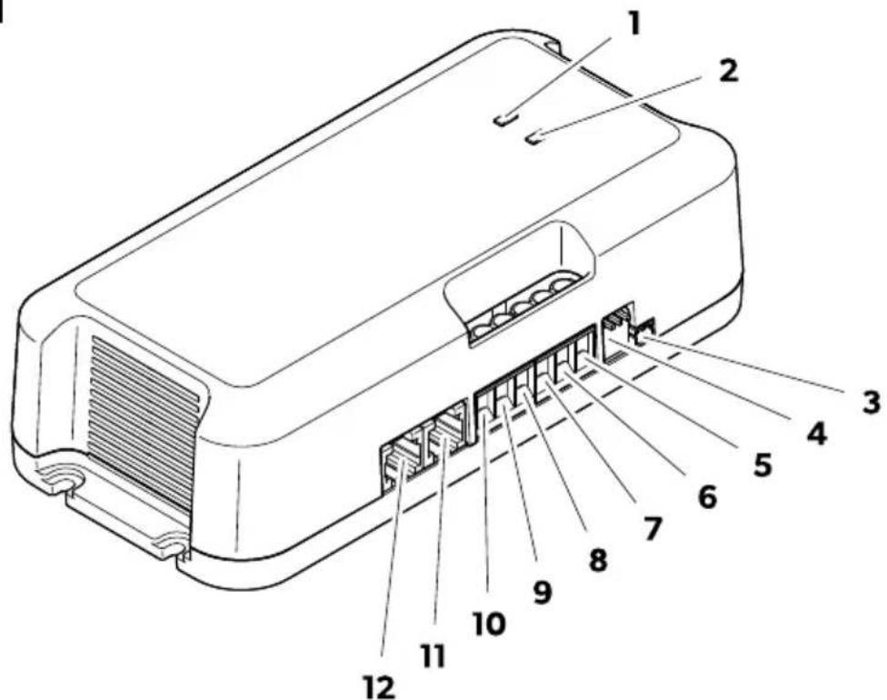
Table 210: Connection control
Connection option A (only for SC330)
Connection option for solar panel output 240 Wp.
To connect the solar charge controller, follow the instructions in Fig. 4 on page 440.
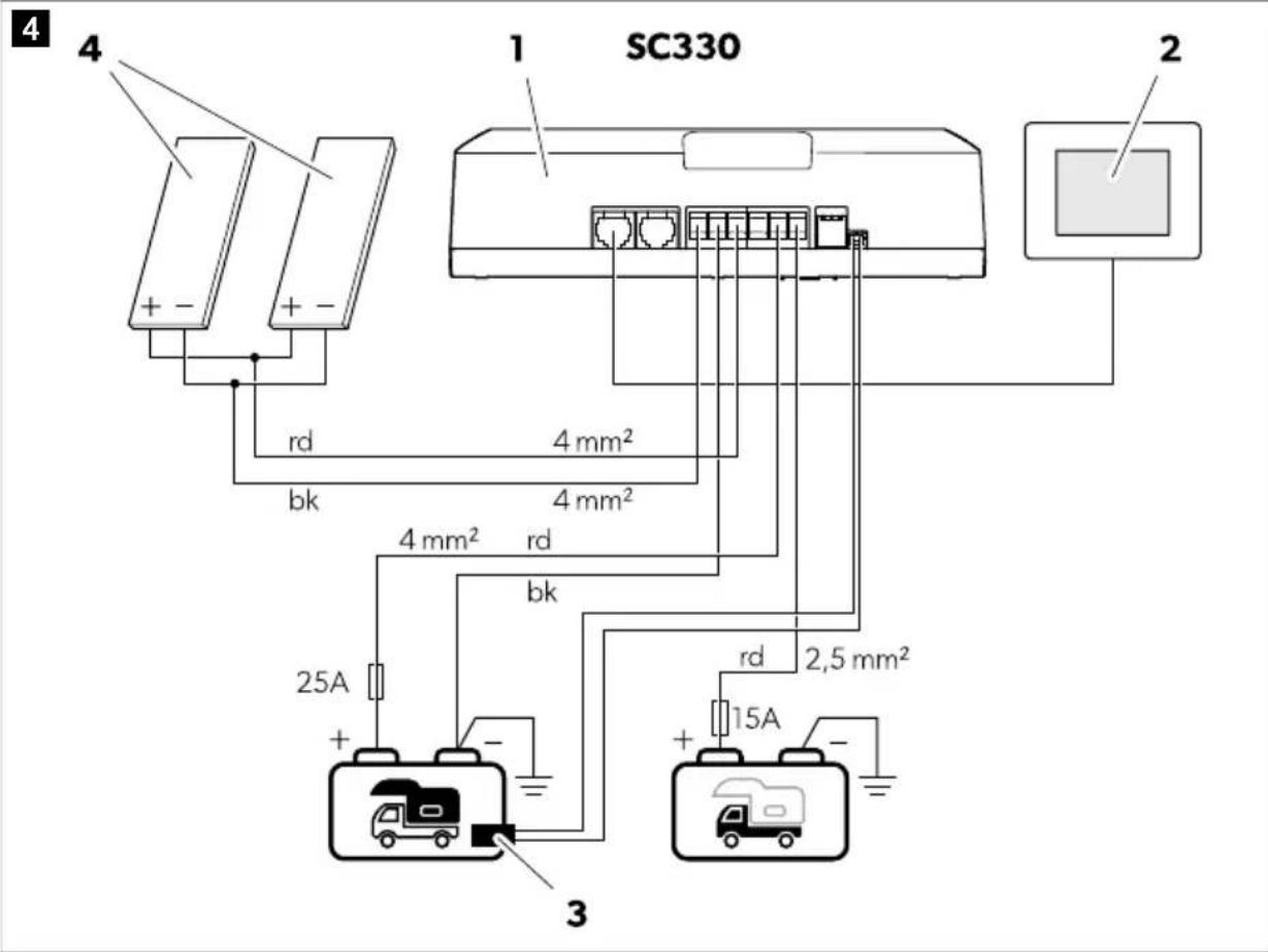
Table 212: Connection diagram for SC330
Connection option B (only for SC330)
Connection option for solar panel output 240 Wp.
To connect the solar charge controller, follow the instructions in Fig. 5 on page 441.
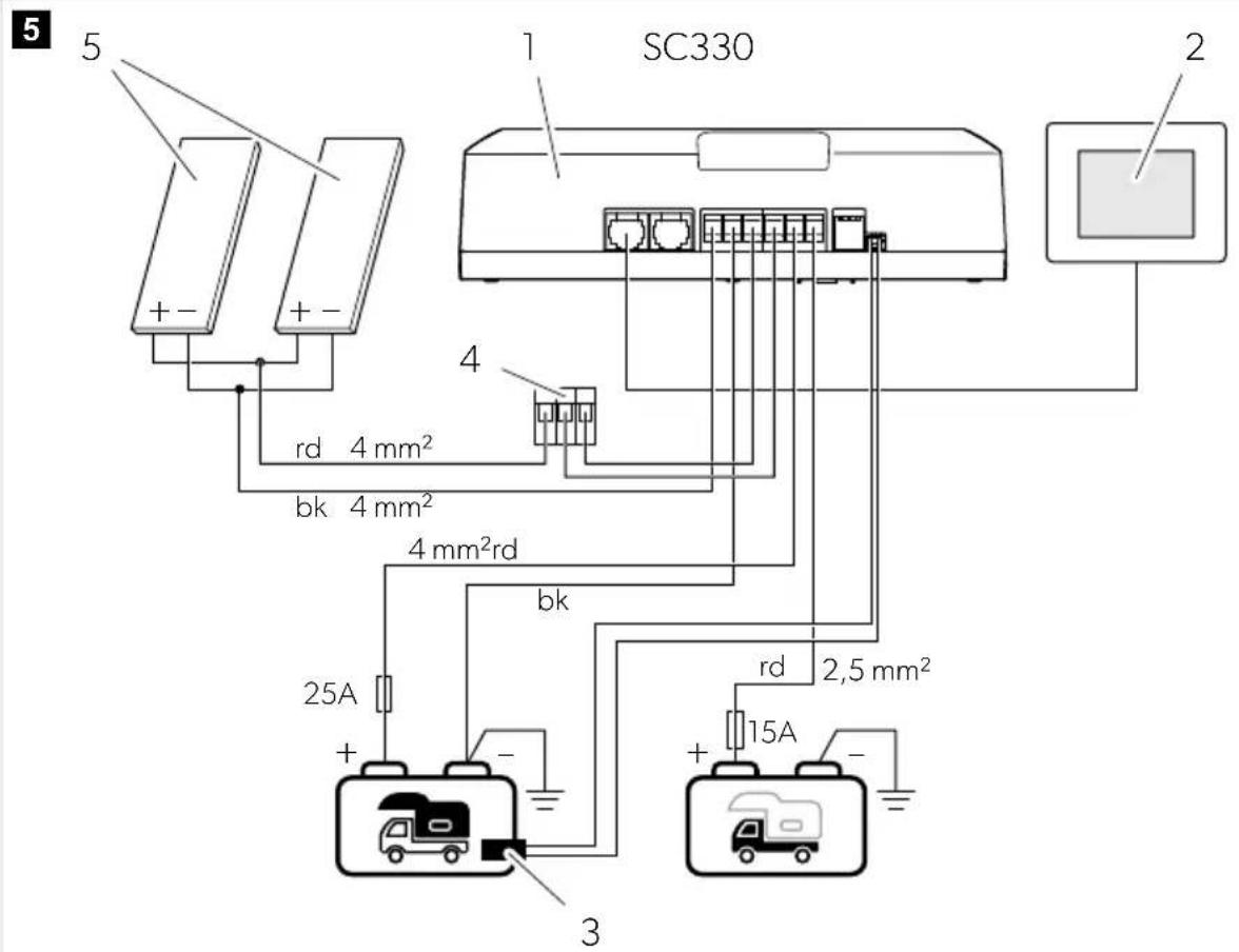
Table 214: Connection diagram for SC330
Connection variant C (only for SC480)
To connect the color charging device, follow the instructions in fig. 6 on page 442.
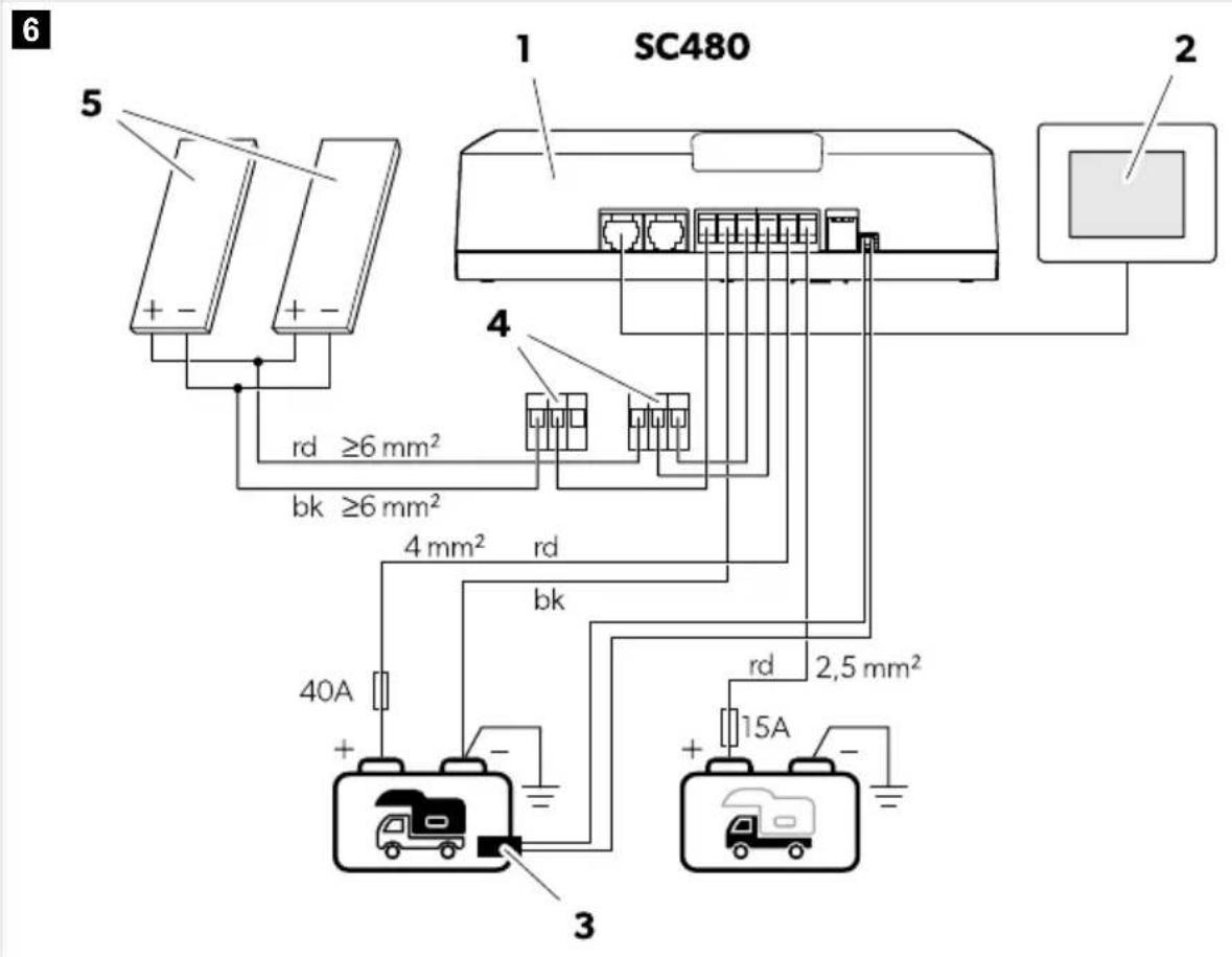
Table 216: Connection diagram for SC480
| № Onисанne | |
| 1 Контrolер за сльнuele зараздаheade | |
| 2 Сених доспей TD283 (akcescoap) | |
| 3 Сенир за Temпера typa | |
| 4 Конektор WAGO | |
| 5 Сола repEN(Hи) панел(N) | |
| Бастория на кубату |
| Старов akumунатор (,onис) |
Table 217: Color contrast
| Кoа Л breast | |
| rd червен | |
| bk черен | |
Connection variant D (only for SC480)
To connect the color charging device, follow the instructions in fig. 7 on page 443.
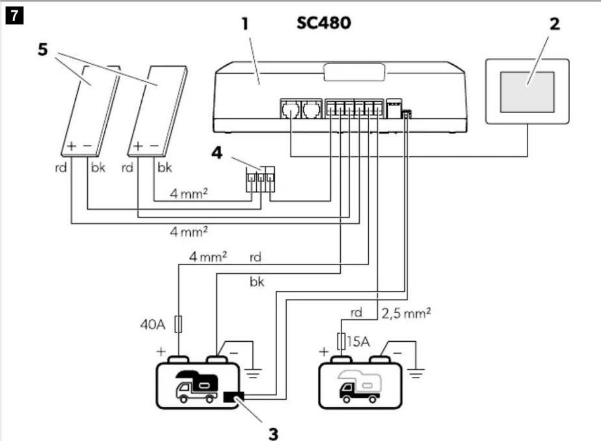
Table 218: Connection diagram for SC480
WARNING! Risk of damage
- Use only batteries that are suitable for the intended charging voltage.
- Use a small screwdriver to carefully set the switches to the required position.
Select a charging program suitable for the type of household battery used, based on the battery manufacturer's specifications, the charging curve information (see chapter Charging functions for batteries on page 436) and the technical data (see chapter Technical data on page 449). The recommended charging times are given for an average ambient temperature of 20°C.
Set the switches to the position shown in the table below to set the charging program for the corresponding battery type.
Table 220: Charging curve configuration
| Положения
На превкуда-
вател(си BO) | Жела на рогама за заразхдане Положения
На певкуда-
вател(си BO) | Жела на рогама за заразхданe |
| 123
ON | Онон reл akymу latор (14,2 V)
• U1: 14,2 V (90 ... 360 min)
• U2: 13,6 V | 123
ON
LiFePO4 akymу latорn (14,4 V)
• U1: 14,4 V (20 ... 60 min)
• U2: 13,8 V |
| Положения
На превкуда-
вател(сиво) | Желая погама за заразждане Положения
На певкуда-
вател(сиво) | Желая погама за заразжданe |
| 123
ON | Оловно-кисellenннakумунatори
(14,4 V) по
AGM1akуmunatори (14,4 V)
•U1:14,4V(30...240min)
•U2:13,6V | LiFePO4akymunatopn(14,2V)
•U1:14,2V(30min)
•U2:13,6V |
| 123
ON | AGM2akumunatopn(14,7V)
•U1:14,7V(30...180min)
•U2:13,6V | LiFePO4akymunatopn(14,6V)
•U1:14,6V(20...60min)
•U2:13,8V |
| 123
ON | AGM2akumunatopnс десуфп-
pane(14,7V)
•U1:14,7V(30...180min)
•U2:13,6V
•U3:15,7V | LiFePO4akymunatopn(14,5V)
•U1:14,5V(30...90min)
•U2:- |
Performing a functional test of the system
The device is pre-configured to charge two batteries: one house battery (B1) and one starter battery (B2), with priority charging of the house battery.
The house battery is charged under the following conditions:
The connected solar panels provide voltage >16 V. - The battery voltage is >8 V.
The house battery will be charged with the selected charging curve (see chapter Battery Charging Settings on page 444).
The starter battery is charged under the following conditions:
- The house battery is in charging state (float), and the starter battery voltage is <12.5 V. - The starter battery voltage is <11.9 V for 20 min.
Each charging phase has a maximum operating time. The phase is switched off when the battery is fully charged and then recharging (float) occurs, which constantly monitors the state of charge (SoC) and, if necessary, provides pulses to keep the battery charged to 100%.
- 1. Cover all solar panels with an opaque cloth or material to prevent the generation of electrical energy. 2. Disconnect the connection to all other power sources (e.g., battery chargers). 3. Measure the battery voltage (value 1) with a voltmeter.
- Remove the cover from all solar panels. Ensure that the solar panels are exposed to sunlight for optimal operation.
- Measure the battery voltage (value 2) with a voltmeter. Compare value 2 with the value from the previous measurement.
Value 2 must be higher than value 1.
- Set the charging current using the rotary switch, adjusted according to the sensor TD283 (accessory).
Removal of the SunControl app
The pre-configured device can be monitored and controlled via Bluetooth with the app installed on a mobile device.
Download the SunControl app from the App Store or Google Play:

qr.dometic.com/beWnPI.
Please note that the SunControl app may not be available in your country.
12 Troubleshooting
Problem Possible cause Solution
The device does not work. The LEDs do not light up.
Faulty fuse, broken or loose connection in the cable.
Check the cables for damage, breaks, or loose connections.
The device does not work properly (low power). Objects are blocking the sunlight.
Blocking of the solar panels.
If you cannot fix the problem, contact an authorized service agent.
Check for obstructions and make sure the solar panels are not blocked by shade. Move the vehicle to a suitable location. Remove any obstructions. Let the solar panels cool down.
| пробlem поочино Решения | |
| > Празмосте ту ватомови на по-
пождюшо място.
> Осироте достатуна уркул-
ся на Вьздуна okonto соларни-
панeti.
> Изваде т_PREдимаителя OT конт-
pondерета за слльчево за佩жда-
н празовete наразожени.To на соларни наен (VOC) на kont-
pondерета за слльчево за佩жда-
.
> Празовete соларни наени
3a мікpopунійпі.
> Празовete соларни наени
3a разсюгы.
> Смене лесфektнite соларни
панeti, akо e необхочимo. |
| Генерия се Кьсо сьединения. |
| Спьчевого заю устристwo He
разOTN. СvetODIObT 3a сьstюнe на
Домашни akymunatopr (B1) мira в чер-
вен. | Само LiFePO4 akymunatори: Сеньо-
рът за Tempepatура не e сььрзан. |
| Спьчевого заю устристwo He
разOTN. Двata сvetODIOda (B1 и B2)
Мигат в чeredио. | Праздимаитял на устристwo
Ту Тая Быд оьбдemeон, сп =
Като e бил заide CTВAN OT пеко-
мерен тok (Викто пава Смяну
Бушona на сTRAпица 446).
> Праздимаитял на смени са-
мо от Квал�фширан nepcohand. |
13 Disposal

Recycling of packaging materials: Recycle the packaging where possible.
Dispose of batteries, rechargeable batteries, or light sources separately from other waste.
- If the product is used improperly, we warn that the battery may leak light, and it is not necessary to remove it before disposing of the product.
- If you want to finally dispose of the product, contact a local recycling center or a specialized company for details on how this should be done in accordance with your regulations.
- The product should be disposed of free of charge.
14 Warranty
The warranty period is defined by law. If the product is defective, please contact the manufacturer's dealer in your country (dometic.com/dealer) or your local dealer.
For warranty processing and repair, please attach the relevant documents when submitting the device:
- A copy of the receipt with the date of purchase - a description of the defect
Please note that self-repair or non-professional repair may have consequences for safety and may void the warranty.
15 Technical data
| SC330 SC480 |
| Мakсмално наразожения на сорони панen (VoC) 32 V | - |
| Прелорытелна мошоста на сорони панen 75 ... 330 Wp 110 ... 480 Wp |
| Изхoden домашен akумунатор (В1) |
| Номинално наразожения 12 V | |
| Мakсмален тok на заразхдане 20 A 30 A | |
| Небхдим e минмален калшитет на akумунаторa | |
| Олвна касенина 60 Ah 100 Ah | |
| LiFePO4 40 Ah 60 Ah | |
| Минмално наразожения на akумунаторa 8 V | - |
| Р发电机по отtemпература наразхдане Do - | 0,03 V/°C |
| Изхoden стартов akумунатор (В2) |
| Номинално наразожения 12 V | |
| Мakсмален тok на заразхданe | 10 A |
| Минмално наразожения на akумунаторa 8 V | - |
| ОБочиTekнчески данни |
| Мakсмална консмача на тok вразжим на готов-hoc't | 0.6 mA |
| Вършен пedingалten | 30 A |
| Околна Temпегатура за равota | -20 °C ... 50 °C |
| Влажно на okолнatable среа | 0.90 %, 6e3 кондэнзашя |
| Разmersи | 170 mm × 88 mm × 48 mm |
| Тergо | 305 g 345 g |
| Чебтона лentesа (Wi-Fi) | 2,4 GHz ISM пenta (2400 ... 2484 MHz) |
| Радочestотна ИЗхODна мошост | 4 dBm (Bluetooth V5.0 Single Mode LE) |
| Серг骞шипанe | CE UK CA E24 1CR-06/02 4836 00 |
Dometic Mobile Power Italy S.r.l. hereby declares that the radio equipment types SC330 and SC480 comply with Directive 2014/53/EU. The full text of the EU declaration of conformity is available at the following internet address: documents.dometic.com
The optional control can be ordered and installed via Bluetooth. The device is compatible with various systems.
Download the SunControl app from the App Store or Google Play:
qr.dometic.com/beWnPI.
qr.dometic.com/beWnPI.
Please note that the SunControl app may not be available in your country.
qr.dometic.com/beWnPI.
dometic.com/sales-offices