
SC1230 - Solar charge controller DOMETIC - Free user manual and instructions
Find the device manual for free SC1230 DOMETIC in PDF.
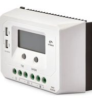


| Product Type | Solar Charge Controller (PWM) |
| Model | SC1230-PWM (Ref. no. 9600005819) |
| Nominal System Voltage | 12/24 V DC (auto-detection) |
| Rated Charge/Discharge Current | 30 A at 55 °C |
| Max. PV Open Circuit Voltage | 50 V |
| Battery Voltage Input Range | 9 V to 32 V |
| Battery Types Supported | Sealed (default), Gel, Flooded |
| Charging Stages | 3-stage: Bulk, Boost/Equalize, Float |
| Equalize Charging Voltage | Sealed: 14.6 V; Flooded: 14.8 V; Gel: N/A |
| Boost Charging Voltage | Sealed: 14.4 V; Gel: 14.2 V; Flooded: 14.6 V |
| Float Charging Voltage | 13.8 V (all types) |
| Low Voltage Disconnect (LVD) | 11.1 V |
| Low Voltage Reconnect (LVR) | 12.6 V |
| Self-Consumption | ≤9.2 mA (12 V), ≤11.7 mA (24 V) |
| Temperature Compensation | -3 mV/°C/2 V at 25 °C |
| USB Output | 5 V DC, 2.4 A (total, 2 ports) |
| Protective Functions | Battery overvoltage, over-discharge, overheating; load overload/short circuit; reverse polarity; controller overheating |
| Display | LCD showing PV voltage/current/power, battery voltage/current/temperature, battery type, load current/power |
| Operating Temperature | -25 °C to +55 °C |
| Enclosure Rating | IP30 |
| Dimensions (W x H x D) | 181 x 100.9 x 59.8 mm |
| Weight | 0.55 kg |
| Terminal Capacity | 16 mm² / 6 AWG |
| Grounding | Common positive |
Frequently Asked Questions - SC1230 DOMETIC
User questions about SC1230 DOMETIC
0 question about this device. Answer the ones you know or ask your own.
Ask a new question about this device
Download the instructions for your Solar charge controller in PDF format for free! Find your manual SC1230 - DOMETIC and take your electronic device back in hand. On this page are published all the documents necessary for the use of your device. SC1230 by DOMETIC.
USER MANUAL SC1230 DOMETIC
SC1230-PWM
EN
30 A Solar Charge Controller
Installation and Operating Manual.....3
Please read this instruction manual carefully before installation and first use, and store it in a safe place. If you pass on the product to another person, hand over this instruction manual along with it.
Table of contents
1 Explanation of symbols....3 2 General safety instructions ....4 3 Scope of delivery 6 4 Intended use ....6 5 Technical description ....6 6 Installing the solar charge controller ....10 7 Using the solar charge controller....14 8 Troubleshooting....17 9 Maintaining and cleaning the product. 17 10 Warranty ....18 11 Disposal....18 12 Technical data....19
1 Explanation of symbols

WARNING!
Safety instruction: Failure to observe this instruction can cause fatal or serious injury.

CAUTION!
Safety instruction: Failure to observe this instruction can lead to injury.

NOTICE!
Failure to observe this instruction can cause material damage and impair the function of the product.

NOTE
Supplementary information for operating the product.
2 General safety instructions
The manufacturer accepts no liability for damage in the following cases:
- Damage to the product resulting from mechanical influences and excess voltage • Alterations to the product without express permission from the manufacturer
- Use for purposes other than those described in the operating manual
The declaration of conformity can be requested from the manufacturer (contact information on the back).
Note the following basic safety information when using electrical devices to protect against:
- Electric shock
- Fire hazards
- Injury
2.1 General safety

WARNING!
- Only use the device as intended.
- Disconnect the device – Before cleaning and maintenance
- After use – Before changing a fuse
- The device may not be used if the device itself or connection cables are visibly damaged.
• This appliance may only be repaired by qualified personnel.
Inadequate repairs may cause serious hazards.
- This appliance cannot be used by children or by persons with reduced physical, sensory, or mental capabilities, or lack of experience and knowledge.
• Electrical devices are not toys.
Always keep and use the device out of the reach of children.
- Children must be supervised to ensure that they do not play with the appliance.

NOTICE!
- Check the manufacturer's data for your battery and ensure that the maximum voltage of the solar charge controller does not exceed the manufacturer's recommended charging voltage.
- Do not use the solar charge controller to charge non-rechargeable batteries.
- Be sure to connect the battery before exposing the solar panel to the sun.
- Before using the device for the first time, check that the voltage specification on the rating plate matches that of the power supply.
- Store the device in a dry and cool place.
2.2 Safety when installing the device

WARNING!
- The electrical installation may only be connected by qualified personnel and only in accordance with the national regulations. Incorrect connection may cause severe hazards.
- Take the precautions necessary to ensure that children cannot interfere with operation. Dangerous situations may occur which cannot be recognised by children.

NOTICE!
- Do not expose the device to a heat source (direct sunlight, heating etc.). Avoid additional heating of the device in this way.
Electrical cables

CAUTION!
- Lay the cables so that they cannot be tripped over or damaged.

NOTICE!
- If cables have to be fed through metal walls or other walls with sharp edges, use ducts or bushings to prevent damage.
- Do not lay cables which are loose or bent next to electrically conductive material (metal).
- Do not pull on the cables.
- Do not lay AC cables and DC cables in the same duct.
- Fasten the cables securely.
2.3 Operating the device safely

WARNING!
- All lead acid batteries produce harmful and explosive gases. The battery should be mounted in a well ventilated area, as far as possible from any ignition source. Do not smoke when in the vicinity of the battery under charge.

NOTICE!
- Do not disconnect any cables when the device is still in use.
3 Scope of delivery
• SC1230-PWM solar charge controller • Installation and operating manual
4 Intended use
The SC1230-PWM solar charge controller (ref. no. 9600005819) can be installed in motorhomes or caravans to be connected to solar panels to charge house batteries.
The device may only be used inside the vehicle.
5 Technical description
The SC1230-PWM solar charge controller enables mobile power supply from solar panels for 12 V==/24 V== devices and two USB devices. The devices can be simultaneously supplied with power while the 12 V==/24 V== battery is being charged.
The solar charge controller ensures that the power supplied by your solar panels is at the right voltage to charge your home or auxiliary battery. The solar charge controller is PWM controlled. It is an intelligent 3 stage solar controller.
Solar charge controller
The solar charge controller has the following functions:
- PWM controlled
- Three stage charging (Bulk, Boost/Equalize, Float)
- Battery types selectable: Sealed, Gel, and Flooded
- LCD display dynamically showing operating data and working conditions
- Two USB output ports (maximum output 2.4 A) for charging electronic devices
The solar charge controller has the following protective functions:
- Battery overvoltage protection
- Battery overheating protection
- Battery over-discharge protection
- Load overload protection
- Load short circuit protection
- Controller overheating protection
- Incorrect polarity protection for solar module and battery
Battery temperature sensor (available as an accessory)
The battery temperature sensor allows the solar charge controller to continuously adjust the charge voltage based on the measured battery temperature. Temperature compensation of the charge voltage ensures that the battery receives the proper charge voltage as the battery temperature changes during normal operation.
5.1 Connecting and operating elements

| No. in fig. 1 | Description |
| 1 | D i s p l a y |
| 2 MENU button – Browse interface | |
| – Set parameters | |
| 3 SET button – Load ON/OFF | |
| – Clear errors | |
| – Enter into Set mode | |
| – Save data | |
| 4 Temperature sensor port | |
| 5 Solar panel terminals | |
| 6 Battery terminals | |
| 7 Load terminals | |
| 8 USB output ports | |
5.2 Display elements
| 2 |  | |
| Source Display Description | ||
| PV with menus solar voltage (V), solar current (A), solar power (kWh) | Day | |
| Night | ||
| No charging | ||
| Charging | ||
| BATT. with menus battery voltage (V), battery current (A) battery temperature (°C/°F)) | Battery capacity, in charging | |
| BATT.TYPE | Battery type | |
| LOAD with menus load current (A), load power (kWh), load mode | Load on | |
| Load off | ||
6 Installing the solar charge controller
6.1 Mounting the solar charge controller
When selecting the installation location, note the following:
- The device must be installed vertically on a wall.
- The device must be installed on a level and sufficiently sturdy surface.
- The device must be installed in a location that is protected from moisture.
- Do not install the device in a dusty environment.
- There should be a space of 10 cm on all sides around the device.

NOTE
Before drilling any holes, make sure that no electrical cables or other parts of the vehicle can be damaged by drilling, sawing and filing.

▶ Attach the device with 4 flat-headed screws.
6.2 Connecting diagram

WARNING!
- Always observe the following connection sequence. Overvoltage can damage the electronics of the device.
- Connecting the solar panel: Connect the battery, then connect the solar panel, finally connect the load.
- Disconnecting the solar panel: Disconnect the load, then disconnect the solar panel, and finally disconnect the battery.
- Do not insert the fuse or turn on the breaker during installation.
- Ensure that the battery clamps do not come into contact with each other. Make sure that the polarity is correct.

Key to connecting diagram
No. in fig. 4
Description
1 Solar charge controller
2 USB output ports
| 3 | L | o | a | d | ||||
| 4 | F | u | s | e | ||||
| 5 | 1 | 2 | V | ---/24 V--- battery | ||||
| 6 | F | u | s | e | ||||
| 7 | I | n | v | e | r | t | e | r |
| 8 | F | u | s | e | ||||
| 9 Solar panel | ||||||||
| 10 Circuit breaker | ||||||||
Lay all the necessary lines. Plan the distribution and fuse protection of the circuits carefully. The battery fuse should be installed as close to the battery as possible. The suggested distance is within 150 mm. Make sure that all lines are inserted and connected properly. Secure all lines with strain relief clamps.
6.3 Connecting the solar charge controller

WARNING!
Make sure that all connections and wiring are conducted by a qualified electrician.
Connecting to the battery

NOTE
Battery voltage less than 6 V will not be recognized by the solar charge controller.
Always connect the battery first, in order to allow the solar charge controller to recognize the system voltage.
▶ Connect the battery as shown in the connecting diagram. ▶ Check if the display of the controller is on.
Connecting a 12 V==/24 V== device or inverter

NOTICE!
Connect the inverter or other load that has the largest start current to the battery rather than to the controller load terminals, if the inverter or other load is necessary.
▶ Connect the lead to the positive (+) and negative (−) terminal. Ensure that the connection is secure and tight.
Connecting the solar panel
▶ Connect the lead to the positive (+) and negative (−) terminal. Ensure that the connection is secure and tight.
Connecting the temperature sensor (available as an accessory)
The battery temperature sensor allows the solar charge controller to continuously adjust charge voltage based on measured battery temperature.
▶ Attach temperature sensor to the battery with tape, ensuring good contact.
7 Using the solar charge controller
7.1 Browsing the display
The display automatically cycles through the menus.
▶ Press the MENU button to switch from one menu to the next menu.
7.2 Setting the solar charge controller
Zero clearing the accumulative power
▶ Press the MENU button until you get to the PV solar power menu. ▶ Press and hold the SET button for 5 s. √ The value flashes. ▶ Press the SET button again to clear the value.
Setting the temperature unit
▶ Press the MENU button until you get to the BATT. temperature menu. ▶ Press and hold the SET button to switch between °C and °F.
Setting the load mode
▶ Press the MENU button until you get to the LOAD mode menu. ▶ Press and hold the SET button for 5 s.
√ The number flashes.
▶ Press the MENU button to set the parameter (see table below). ▶ Press the SET button again to confirm the number.
| No. | Load menu 1 | No | Load menu 2 |
| 100 Light ON/OFF 2n Disabled | |||
| 101 Load will be on for 1 hour since sunset | 201 Load will be on for 1 hour before sunrise | ||
| 102 Load will be on for 2 hours since sunset | 202 Load will be on for 2 hours before sunrise | ||
| 103 – 113 Load will be on for 3 to 13 hours since sunset | 203 – 213 Load will be on for 3 to 13 hours before sunrise | ||
| 114 Load will be on for 14 hours since sunset | 214 Load will be on for 14 hours before sunrise | ||
| 115 Load will be on for 15 hours since sunset | 215 Load will be on for 15 hours before sunrise | ||
| 116 Test mode | 2n Disabled | ||
| 117 Manual mode (Default load ON) | 2n Disabled | ||
Setting the battery type
▶ Press the MENU button until you get to the BATT. voltage menu. ▶ Press and hold the SET button for 5 s.
![graph LR A["BATT. TYPE SEL"] --> B["BATT. TYPE GEL"] B --> C["BATT. TYPE FLD"]](/content/2026/05/905110/images/f5777bb89d68d724597e53a8a49da2977d3e7f09c7cadb80e7ce8a49b5696053.jpg)
▶ Press the MENU button to switch between the battery types (SEL: Sealed (Default), GEL: Gel, FLD: Flooded). ▶ Confirm the battery type by pressing the SET button or waiting for 5 s.
7.3 Protective functions of the solar charge controller
| Protection Conditions Status | ||
| Solar module reverse polarity | The solar module can be reversed, when the battery is connected correctly. | The controller is not damaged |
| Battery reverse polarity | The battery can be reversed, when the solar module is not connected. | |
| Battery overvoltage | The battery voltage reaches to the OVD (over voltage/disconnect voltage point) | Stop charging |
| Battery overdischarge | The battery voltage reaches to the LVD (above low voltage/reconnect voltage point) | Stop discharging |
| Battery overheating | Temperature sensor is higher than 65 °C Output is OFF | |
| Temperature sensor is less than 55 °C Output is ON | ||
| Solar charge controller overheating | Temperature sensor is higher than 85 °C Output is OFF | |
| Temperature sensor is less than 75 °C Output is ON | ||
| Load overload | Load current ≥2.5 times rated current | Output is OFF. |
| 1.02 to 1.05 times, 50 s, | Clear the fault: Restart the controller or wait for one night-day cycle (night time >3 hours). | |
| 1.05 to 1.25 times, 30 s | ||
| 1.25 to 1.35 times,10 s | ||
| 1.35 to 1.5 times, 2 s | ||
| Damaged temperature sensor | The temperature sensor is short-circuited or damaged | Charging or discharging at 25 °C |
8 Troubleshooting
If you are unable to rectify the fault, get in touch with a specialist workshop.
| Display | Fault | Possible cause | Suggested remedy |
| The Display is off during daytime when sunshine falls on solar modules properly. | Solar panel disconnected | Confirm that solar module wire connections are correct and tight. | |
| Wire connection is correct, display is off. | Battery voltage is lower than 9 V | Check the voltage of battery. At least 9 V voltage is required to activate the solar charge controller. | |
| PV voltage is less than battery voltage | Check the PV input voltage which should be higher than battery's voltage. | ||
 | Display is flashing. Battery over voltage | Check if the battery voltage is higher than over voltage/disconnect voltage point, and disconnect the solar panel. | |
 | Display is flashing. Battery over discharged | When the battery voltage is restored to or above low voltage/reconnect voltage point, the load will recover | |
 | Display is flashing. Battery overheating | The solar charge controller will automatically turn the system off. But while the temperature declines to be below 50 °C, the solar charge controller will resume work. | |
 | Display is flashing. Over load or short circuit | Reduce the number of electric equipments or check carefully loads connection. | |
9 Maintaining and cleaning the product
Place the packaging material in the appropriate recycling waste bins wherever possible.

If you wish to finally dispose of the product, ask your local recycling centre or specialist dealer for details about how to do this in accordance with the applicable disposal regulations.
10 Warranty
The statutory warranty period applies. If the product is defective, please contact the manufacturer's branch in your country (see the back of the instruction manual for the addresses) or your retailer.
For repair and guarantee processing, please include the following documents when you send in the device:
• A copy of the receipt with purchasing date - A reason for the claim or description of the fault
11 Disposal
Place the packaging material in the appropriate recycling waste bins wherever possible.

If you wish to finally dispose of the product, ask your local recycling centre or specialist dealer for details about how to do this in accordance with the applicable disposal regulations.
12 Technical data
| SC1230-PWM | |
| Ref. no.: 9600005819 | |
| Nominal system voltage: | 12/24 V---, Auto |
| Battery input voltage range: 9 V to 32 V | |
| Rated charge/discharge current: 30 A at 55 | °C |
| Max. PV open circuit voltage: 50 V | |
| Battery type: Sealed (Default)/Gel/Flooded | |
| Equalize charging voltage: | Sealed:14.6 V/Gel: No/Flooded:14.8 V |
| Boost charging voltage: | Sealed:14.4 V/Gel:14.2 V/Flooded:14.6 V |
| Float charging voltage: Sealed/Gel/Flooded | d:13.8 V |
| Low voltage reconnect voltage: | Sealed/Gel/Flooded:12.6 V |
| Low voltage disconnect voltage: | Sealed/Gel/Flooded:11.1 V |
| Self-consumption: | ≤9.2 mA/12 V ≤11.7 mA/24 V |
| Temperature compensation coefficient: | -3 mV/°C/ 2 V at 25 °C |
| Charge circuit voltage drop: | ≤0.29V |
| Discharge circuit voltage drop: | ≤0.16V |
| LCD temperature range: | -20 °C to +70 °C |
| Working environment temperature: | -25 °C to +55 °C |
| Relative humidity: | 95%, N.C. |
| Enclosure: | IP30 |
| Grounding: | Common positive |
| USB output: | 5V DC/2.4 A (total) |
| Dimensions (W x H x D) in mm: | 181 x 100.9 x 59.8 |
| Terminals: | 16 mm²/6AWG |
| Weight: | 0.55 kg |
dometic.com
YOUR LOCAL DEALER
dometic.com/dealer
YOUR LOCAL SUPPORT
dometic.com/contact
dometic.com/sales-offices
- A SOLAR CHARGE CONTROLLER
- TABLE OF CONTENTS
- EXPLANATION OF SYMBOLS
- WARNING
- CAUTION
- NOTICE
- NOTE
- GENERAL SAFETY INSTRUCTIONS
- GENERAL SAFETY
- SAFETY WHEN INSTALLING THE DEVICE
- ELECTRICAL CABLES
- OPERATING THE DEVICE SAFELY
- SCOPE OF DELIVERY
- INTENDED USE
- TECHNICAL DESCRIPTION
- SOLAR CHARGE CONTROLLER
- BATTERY TEMPERATURE SENSOR (AVAILABLE AS AN ACCESSORY)
- CONNECTING AND OPERATING ELEMENTS
- DISPLAY ELEMENTS
- INSTALLING THE SOLAR CHARGE CONTROLLER
- MOUNTING THE SOLAR CHARGE CONTROLLER
- CONNECTING DIAGRAM
- KEY TO CONNECTING DIAGRAM
- NO. IN FIG
- DESCRIPTION
- CONNECTING THE SOLAR CHARGE CONTROLLER
- CONNECTING TO THE BATTERY
- CONNECTING A 12 V==/24 V== DEVICE OR INVERTER
- CONNECTING THE SOLAR PANEL
- CONNECTING THE TEMPERATURE SENSOR (AVAILABLE AS AN ACCESSORY)
- USING THE SOLAR CHARGE CONTROLLER
- BROWSING THE DISPLAY
- SETTING THE SOLAR CHARGE CONTROLLER
- ZERO CLEARING THE ACCUMULATIVE POWER
- SETTING THE TEMPERATURE UNIT
- SETTING THE LOAD MODE
- SETTING THE BATTERY TYPE
- PROTECTIVE FUNCTIONS OF THE SOLAR CHARGE CONTROLLER
- TROUBLESHOOTING
- MAINTAINING AND CLEANING THE PRODUCT
- WARRANTY
- DISPOSAL
Brand : DOMETIC
Model : SC1230
Category : Solar charge controller