CS 45 18.0-EC C - Saw Flex - Free user manual and instructions
Find the device manual for free CS 45 18.0-EC C Flex in PDF.

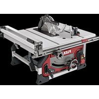
| Product Type | Manual Circular Saw |
| Brand | Flex |
| Model | CS 45 18.0-EC C |
| Nominal Voltage | 18 V DC |
| Idle Speed | 5 400 min⁻¹ |
| Blade Diameter | 128 mm |
| Blade Bore | 20 mm |
| Max Cut Depth | 46.5 mm |
| Weight (with battery) | 2.4 kg |
| Battery Weight (5 Ah) | 0.8 kg |
| Sound Pressure Level | 89.3 dB(A) |
| Sound Power Level | 100.3 dB(A) |
| Vibration (cutting boards) | <1.4 m/s² |
| Vibration (cutting metal) | <1.6 m/s² |
| Battery Type | Lithium-ion |
| Functions | Plunge cut, parallel guide, dust extraction |
| Safety | Protective guards (lower and upper), start lock, blade brake (inertia) |
| Maintenance | Regular cleaning of ventilation grills, dry compressed air |
| Included Accessories | Hex key, guide rail (not mentioned but probable) |
Frequently Asked Questions - CS 45 18.0-EC C Flex
User questions about CS 45 18.0-EC C Flex
0 question about this device. Answer the ones you know or ask your own.
Ask a new question about this device
Download the instructions for your Saw in PDF format for free! Find your manual CS 45 18.0-EC C - Flex and take your electronic device back in hand. On this page are published all the documents necessary for the use of your device. CS 45 18.0-EC C by Flex.
USER MANUAL CS 45 18.0-EC C Flex
en Original operating instructions....14
B
natural_image
Technical line drawing showing a device with an open box and a handheld device, both with directional arrows indicating movement (no text or symbols present)C
natural_image
Technical line drawing of a mechanical assembly with no visible text or symbols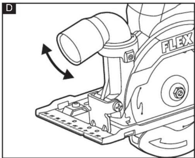
natural_image
Technical line drawing of a mechanical assembly with directional arrows indicating motion (no text or symbols)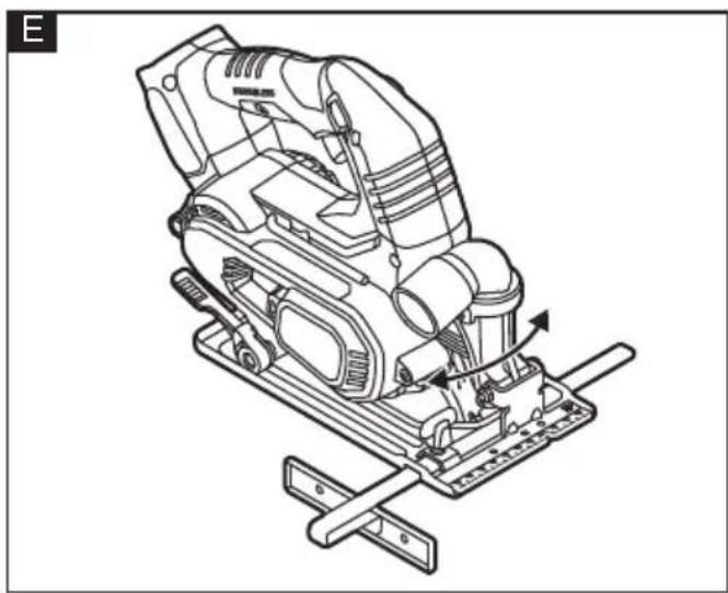
natural_image
Technical line drawing of a mechanical device with no visible text or symbols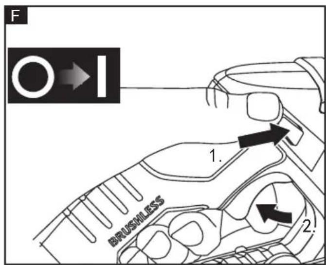
natural_image
Technical line drawing of a mechanical assembly with a saw and gear (no text or symbols)
natural_image
Line drawing of a hand using a power tool to cut a saw blade on a workbench (no text or symbols)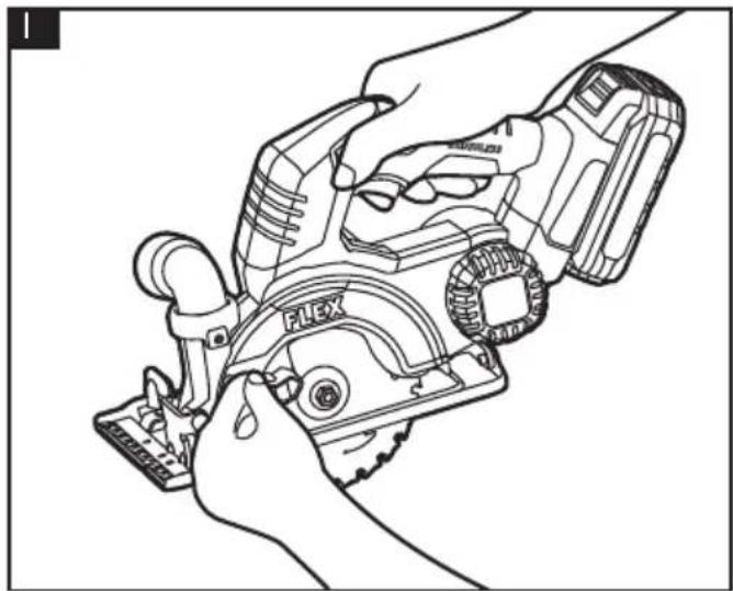
natural_image
Line drawing of hands using a PLEX tool to adjust or install a mechanical component (no text or symbols visible)Symbols used in this manual

WARNING!
Denotes impending danger. Non-observance of this warning may result in death or extremely severe injuries.

CAUTION!
Denotes a possibly dangerous situation. Non-observance of this warning may result in slight injury or damage to property.

NOTE
Denotes application tips and important information.
Symbols on the power tool

To reduce the risk of injury, read the operating instructions!

Wear goggles!

Wear ear protection!

Wear mask!

Disposal information for the old machine
For your safety

WARNING!
Before using the power tool, please read and follow:
– these operating instructions,
- the "General safety instructions" on the handling of power tools in the enclosed booklet (leaflet-no.: 315.915),
– the currently valid site rules and the regulations for the prevention of accidents.
This power tool is state of the art and has been constructed in accordance with the acknowledged safety regulations.
Nevertheless, when in use, the power tool may be a danger to life and limb of the user or a third party, or the power tool or other property may be damaged.
The circular saw may be used only –asintended,
- in perfect working order.
Faults which impair safety must be repaired immediately.
Intended use
The circular saw is designed
– for commercial use in industry and trade,
- for cutting wood lengthways and crossways in straight lines.
Safety warnings for circular saw
Cutting procedures
a) Do not reach underneath the workpiece. The guard cannot protect you from the blade below the workpiece.
b) Adjust the cutting depth to the thickness of the workpiece. Less than a full tooth of the blade teeth should be visible below the workpiece.
c) Never hold the workpiece in your hands or across your leg while cutting. Secure the workpiece to a stable platform. It is important to support the work properly to minimize body exposure, blade binding, or loss of control.
d) Hold the power tool by insulated gripping surfaces, when performing an operation where the cutting tool may contact hidden wiring or its own cord. Contact with a "live" wire will also make exposed metal parts of the power tool "live" and could give the operator an electric shock.
e) When ripping, always use a rip fence or straight edge guide. This improves the accuracy of cut and reduces the chance of blade binding.
f) Always use blades with correct size and shape (diamond versus round) of arbour holes. Blades that do not match the mounting hardware of the saw will run off-centre, causing loss of control.
g) Never use damaged or incorrect blade washers or bolt. The blade washers and bolt were specially designed for your saw, for optimum performance and safety of operation.
Further safety instructions for all saws Kickback causes and related warnings
- kickback is a sudden reaction to a pinched, jammed or misaligned saw blade, causing an uncontrolled saw to lift up and out of the workpiece toward the operator;
- when the blade is pinched or jammed tightly by the kerf closing down, the blade stalls and the motor reaction drives the unit rapidly back toward the operator;
- if the blade becomes twisted or misaligned in the cut, the teeth at the back edge of the blade can dig into the top surface of the wood causing the blade to climb out of the kerf and jump back toward the operator. Kickback is the result of saw misuse and/or incorrect operating procedures or conditions and can be avoided by taking proper precautions as given below.
a) When blade is binding, or when interrupting a cut for any reason, release the trigger and hold the saw motionless in the material until the blade comes to a complete stop. Never attempt to remove the saw from the work or pull the saw backward while the blade is in motion or kickback may occur. /Investigate and take corrective actions to eliminate the cause of blade binding.
b) When restarting a saw in the workpiece, centre the saw blade in the kerf so that the saw teeth are not engaged into the material. If a saw blade binds, it may walk up or kickback from the workpiece as the saw is restarted.
c) Support large panels to minimise the risk of blade pinching and kickback. Large panels tend to sag under their own weight. Supports must be placed under the panel on both sides, near the line of cut and near the edge of the panel.
d) Do not use dull or damaged blades. Unsharpened or improperly set blades produce narrow kerf causing excessive friction, blade binding and kickback.
e) Blade depth and bevel adjusting locking levers must be tight and secure before making the cut. If blade adjustment shifts while cutting, it may cause binding and kickback.
f) Use extra caution when sawing into existing walls or other blind areas. The protruding blade may cut objects that can cause kickback.
Safety instructions for saws with pendulum guard
Lower guard function
a) Check the lower guard for proper closing before each use. Do not operate the saw if the lower guard does not move freely and close instantly. Never clamp or tie the lower guard into the open position. If the saw is accidentally dropped, the lower guard may be bent. Raise the lower guard with the retracting handle and make sure it moves freely and does not touch the blade or any other part, in all angles and depths of cut.
b) Check the operation of the lower guard spring. If the guard and the spring are not operating properly, they must be serviced before use. Lower guard may operate sluggishly due to damaged parts, gummy deposits, or a build-up of debris.
c) The lower guard may be retracted manually only for special cuts such as "plunge cuts" and "compound cuts". Raise the lower guard by the retracting handle and as soon as the blade enters the material, the lower guard must be released. For all other sawing, the lower guard should operate automatically.
d) Always observe that the lower guard is covering the blade before placing the saw down on bench or floor. An unprotected, coasting blade will cause the saw to walk backwards, cutting whatever is in its path. Be aware of the time it takes for the blade to stop after switch is released.
Safety instructions for plunge type saws
Guard function
a) Check the guard for proper closing before each use. Do not operate the saw if the guard does not move freely and enclose the blade instantly. Never clamp or tie the guard so that the blade is exposed. If the saw is accidentally dropped, the guard may be bent. Check to make sure that the guard moves freely and does not touch
the blade or any other part, in all depths of cut.
b) Check the operation and condition of the guard return spring. If the guard and the spring are not operating properly, they must be serviced before use. The guard may operate sluggishly due to damaged parts, gummy deposits, or a build-up of debris.
c) Assure that the base plate of the saw will not shift while performing a "plunge cut". Blade shifting sideways will cause binding and likely kick back.
d) Always observe that the guard is covering the blade before placing the saw down on bench or floor. An unprotected, coasting blade will cause the saw to walk backwards, cutting whatever is in its path. Be aware of the time it takes for the blade to stop after the switch is released.
Noise and vibration
The noise and vibration values have been determined in accordance with EN 62841.
The evaluated noise level of the power tool is typically:
– Sound pressure level L_pA : 89.3 dB(A);
- Sound power level L_WA : 100.3 dB(A);
- Uncertainty: K = 3 dB.
– Total vibration value
- Emission value a_h,B (cutting boards): <1.4 m/s
- Emission value a_h,M (cutting sheet metal): < 1.6 m/s
– Uncertainty: K = 1.5 m/s

WARNING!
The indicated measurements refer to new power tools. Daily use causes the noise and vibration values to change.

NOTE
The vibration emission level given in this information sheet has been measured in accordance with a standardised test given in EN 62841 and may be used to compare one tool with another.
It may be used for a preliminary assessment of exposure. The declared vibration emission level represents the main applications of the tool. However if the tool is used for different applications, with different accessories or poorly maintained, the vibration emission may differ. This may significantly increase the exposure level over the total working period. For a precise estimation of the vibration load
the times should also be considered during which the power tool is switched off or even running, but not actually in use. This may significantly decrease the exposure level over the total working period.
Identify additional safety measures to protect the operator from the effects of vibration such as: maintain the tool and the accessories, keep the hands warm, organisation of work patterns.

CAUTION!
Wear ear protection at a sound pressure above 85 dB(A).
Technical specifications
| CS 45 18.0-EC | ||
| Machine Type Hand circular saw | ||
| U Vdc 18 | ||
| n_o | /min 5 | 400 |
| Blade diameter mm | 128 | |
| Blade bore diameter | mm 20 | |
| Max. cutting depth | mm 46.5 | |
| Weight according to "EPTA Procedure 01/2003" (with battery) | kg 2.4 | |
| weight battery | kg 0.8 | kg (5 Ah) |
Overview (see figure A)
The numbering of the product features refers to the illustration of the machine on the graphics page.
1 Retracting guard
2 Adjusting lever for retracting guard
3 Clamping bolt with clamping flange
4 Dust extraction nozzle
5 Lock-off button
6 ON/OFF switch
7 Handle
8 Hexagon-socket key
9 Base plate
10 Clamping lever for cutting depth
preselection
11 Spindle locking button
12 Edge guide
13 Edge-guide locking knob
Operating instructions

NOTE
When the power tool is switched off, the tool continues running briefly.
For further information on the manufacturer's products go to www.flex-tools.com.

WARNING!
Before performing any work on the power tool, remove the battery pack from the tool.
Before switching on the power tool
Remove the battery pack from the tool and check that there are no missing or damaged parts.
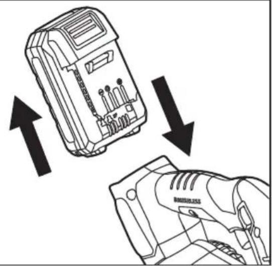
To attach/detach battery pack (See figure B)

CAUTION!
Use of batteries not suitable for the machine can lead to malfunctions of or cause damage to the power tool.
To attach the battery pack:
Align the raised rib on the battery pack with the grooves on the bottom of the tool, and then attach the battery pack to the tool.
Make sure that the latch on the battery pack snaps into place and the battery pack is secured to the tool before beginning operation.
To detach the battery pack:
Depress the battery release button of the battery pack, and pull the battery pack out and remove it from the tool.
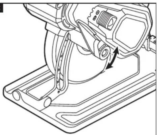
Adjusting the cutting depth (See figure C)
a. Remove the battery first, and then ensure that the saw is facing away from you.
b. Loosen the depth locking lever.
c. Hold the base plate flat against the edge of the workpiece and lift the body of the saw until the blade is at the right depth. Use the depth scale to determine the cutting depth.
d. Tighten the depth locking lever.

CAUTION!
Always use the correct blade depth setting. The correct blade depth setting for all cuts should not be more than 6.35mm below the material being cut. Allowing more depth will increase the chance of kickback and result in a rough cut.
Dust removal device (See figure D)
The dust discharging interface configured by the machine can be adjusted from left to right angle, and the suitable dust discharging direction can be selected according to the working condition
Installing the edge guide (See figure E)
The edge guide allows you to make accurate parallel cuts when trimming a workpiece.
a. Remove the battery.
b. Slide the edge guide into the edge-guide slots at the front of the saw base.
c. Adjust the edge guide to the desired length of cut. Tighten the edge-guide locking knob.
d. Clamp and support the workpiece securely before making your cut.
e. Place the edge guide firmly against the edge of the workpiece. Doing this will give you a true cut without pinching the blade.
f. Be sure that the guiding edge of the workpiece is straight so you can get a straight cut.
g. Always let the blade reach full speed, and then carefully guide the saw into the workpiece.
Switching on and off (See figure F)
The tool is equipped with a lock-off button to avoid unintentional starting.
To switch on, depress the lock-off button and squeeze the trigger switch.
To switch off, release the trigger switch.

CAUTION!
Allow the blade to come to a complete standstill before setting the saw down.
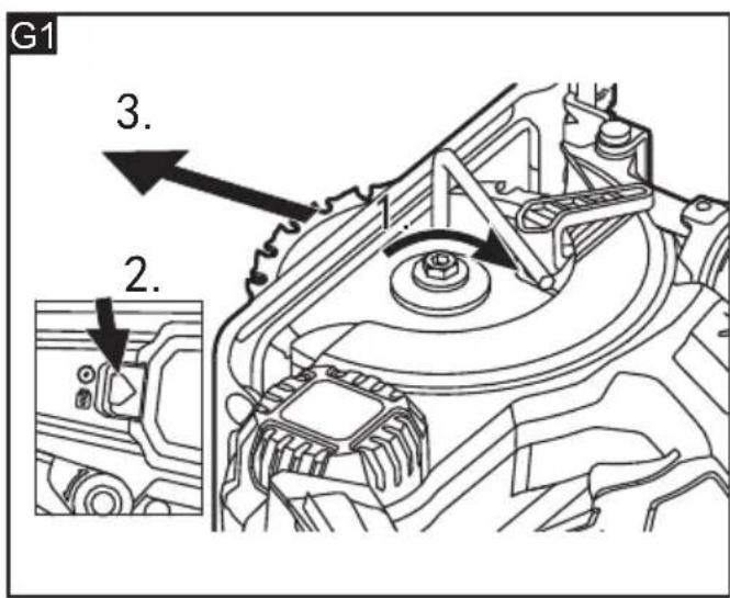
Installing and removing the blade (See figure G1&G2)
WARNING!
Always wear sturdy gloves when handling or changing blades as they can be very sharp. Only use sharp and undamaged saw blades. Cracked or distorted saw blades must be replaced immediately.
WARNING!
Depress the spindle lock only when the tool is at a standstill.
a. Remove the battery first, and then place the saw on its side on a flat surface. Press the spindle lock and turn the blade bolt with included Hexagon-socket key until the lock engages.
b. While pressing the spindle lock, use the supplied Hexagon-socket key to rotate the fixing bolt in the direction of the saw blade.
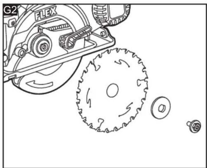
c. Remove the outer blade flange and the blade bolt.
d. Raise the lower blade guard using the blade guard lever. Remove the saw blade from the inner flange and pull it out.
e. Clean the saw blade flanges thoroughly before mounting the new saw blade. Wipe a drop of oil onto the inner and outer flange where they will touch the blade.
f. Mount the new saw blade onto the spindle and against the inner flange.
g. Attach the outer flange and tighten the blade bolt.
Operating instructions
WARNING!
Hold the tool by the insulated grip surfaces only!
WARNING!
Allow the blade to come to a complete standstill before setting the saw down.
Making a cut (See figureH)
a. Mark the line of cut on the workpiece.
b. Rest the front edge of the base on the workpiece.
c. Start the motor by depressing the lock-off button and squeezing the trigger switch.
NOTE: Always let the blade reach full speed before you begin to cut into the workpiece.
d. Slowly push the saw forward.
e. When making a cut always use steady, even pressure. Forcing the saw causes rough cuts and could shorten the life of the saw or cause kickback. Allow the blade and the saw to do the work.
f. After completing your cut, release the trigger switch and allow the blade to come to a complete stop. Do not remove the saw from the workpiece while the blade is moving.
WARNING!
Since blade thickness varies, always make a trial cut in scrap material along the guideline to determine how much, if any, the guideline must be offset to get an accurate cut.
Making a plunge cut (See figure I)
WARNING!
To avoid loss of control, always use extreme caution when making plunge cuts.
Adjust the depth of cut as required.
Raise the lower blade guard lever to expose the saw blade and firmly rest the front of the base flat against the workpiece with the main handle raised so the blade does not touch the workpiece.
With the blade just clearing the workpiece, start the motor by depressing the lock-off button and squeezing the trigger switch,
Always let the blade reach full speed before you begin to cut into the workpiece.
Slowly lower the saw into the workpiece, using the front of the base resting on the workpiece as a hinge point.
WARNING!
As soon as the blade starts cutting the material, release the lower blade guard lever. After completing your cut, release the trigger switch and allow the blade to come to a complete stop. Do not remove the saw from the workpiece while the blade is moving.
WARNING!
Always cut in a forward direction when making a pocket cut. Cutting in the reverse direction could cause the saw to climb up on the workpiece and back toward you, possibly causing serious injury.

WARNING!
Never tie the lower blade guard in a raised position. Leaving the blade exposed could lead to serious injury.
Maintenance and care

WARNING!
Before performing any work on the power tool, remove the battery pack from the tool.
Cleaning
■ Clean the power tool and grille in front of the vent slots regularly. Frequency of cleaning is dependent on the material and duration of use.
■ Regularly blow out the housing interior and motor with dry compressed air.
Spare parts and accessories
For other accessories, in particular tools and accessories, can be found in the manufacturer's catalogues. Exploded drawings and spare-part lists can be found on our homepage: www.flex-tools.com
Disposal information

WARNING!
Render redundant power tools unusable:
- battery operated power tool by removing the battery.

EU countries only
Do not throw electric power tools into the household waste! In accordance with the European
Directive 2012/19/EU on Waste Electrical and Electronic Equipment and transposition into national law used electric power tools must be collected separately and recycled in an environmentally friendly manner.

Raw material recovery instead of waste disposal.
Device, accessories and packaging should be recycled in an environmentally friendly manner. Plastic parts are identified for recycling according to material type.

WARNING!
Do not throw batteries into the household waste, fire or water. Do not open used batteries.
EU countries only:
In accordance with Directive 2006/66/EG defective or used batteries must be recycled.

NOTE
Please ask your dealer about disposal options!
CE-Declaration of Conformity
We declare under our sole responsibility that the product described under "Technical specifications" conforms to the following standards or normative documents: EN 62841 in accordance with the regulations of the directives 2014/30/EU, 2006/42/EG, 2011/65/EU.
Responsible for technical documents: FLEX-Elektrowerkzeuge GmbH, R & D Bahnhofstrasse 15, D-71711 Steinheim/Murr


Peter Lameli Klaus Peter Weinper Technical Head Head of Quality
Department (QD)
Declaration of Conformity
We as the manufacturer: FLEX
Elektrowerkzeuge GmbH, Business address: Bahnhofstr. 15, 71711 Steinheim, Germany declare under our sole responsibility, that the product(s) described under „Technical specifications“ fulfills all the relevant provisions of The Supply of Machinery (Safety) Regulations S.I. 2008/1597 and also fulfills all the relevant provisions of the following UK Regulations:
Electromagnetic Compatibility Regulations S.I. 2016/1091, The Restriction of the Use of Certain Hazardous Substances in Electrical and Electronic Equipment Regulations S.I. 2012/3032 and are manufactured in accordance with the following designated Standards: BS EN 62841-1:2015, BS EN 62841-2-6:2020, BS EN 55014-1:2017, BS EN 55014-2:2015
Place of declaration: Steinheim, Germany. Responsible person: Peter Lameli, Technical Director - FLEX-Elektrowerkzeuge GmbH
Contact details for Great Britain: FLEX Power Tools Limited, Unit 8 Anglo Office Park, Lincoln Road, HP 12, 3RH Buckinghamshire, United Kingdom.

Peter Lameli Klaus Peter Weinper Technical Head Head of Quality Department
12.15.2021
Exemption from liability
The manufacturer and his representative are not liable for any damage and lost profit due to interruption in business caused by the product or by an unusable product. The manufacturer and his representative are not liable for any damage which was caused by improper use of the power tool or by use of the power tool with products from other manufacturers.
Peter Lameli Klaus Peter Weinper Technical Head Head of Quality Department
Peter Lameli Klaus Peter Weinper Technical Head Head of Quality Department
Technical Head Head of Quality
Department (QD)
Peter Lameli Klaus Peter Weinper Technical Head Head of Quality Department
Peter Lameli Klaus Peter Weinper Technical Head Head of Quality Department
(QD)
Disposal information for the old machine
Jūsų saugumui
!ISPÉJIMAS!
Peter Lameli Klaus Peter Weinper Technical Head Head of Quality
Department (QD)
Peter Lameli Klaus Peter Weinper Technical Head Head of Quality
Department (QD)
Technical Head Head of Quality
Department (QD)