690-I - Power tool RIDGID - Free user manual and instructions
Find the device manual for free 690-I RIDGID in PDF.

| Product Type | Pipe threading drive system (electric threader) |
| Brand | RIDGID |
| Model | 690-I |
| Dimensions | 613 mm (length) x 121 mm (width) x 203 mm (height) |
| Weight | 9.6 kg |
| Power supply | Single-phase, 120 V (12 A) or 220-240 V (5 A) |
| Motor power | 1270 W (120 V) / 1020 W (220-240 V) |
| Rotation speed | 36 rpm (120 V) / 32 rpm (220-240 V) |
| Compatible pipe diameter | 1/8" to 2" (3 to 50 mm) |
| Thread type | Right-hand and left-hand threading |
| Die head retention | Retention mechanism for 1 1/2" to 2" diameters; ring spring for 1/8" to 1 1/4" |
| Supplied support | Drive system supports types 691 or 692 |
| Main functions | Pipe and conduit threading, rotation reverser, two-stage on/off trigger |
| Gear housing material | Cast aluminum, permanent lubrication |
| Noise level | Sound pressure 83 dB(A), sound power 94 dB(A) |
| Vibration | Less than 2.5 m/s² |
| Maintenance and cleaning | Clean handles and controls; replace motor brushes if wear < 8 mm; replace dies if dull |
| Safety | Double insulation; mandatory safety glasses; use supplied support; do not wear gloves; disconnect before maintenance |
| Spare parts | Motor brushes, dies, 11-R die head, adapter for small heads |
| Repairability | Repair by RIDGID authorized repairer; technical support at 800-519-3456 |
| Included accessories | Drive system, adapter for 600-I head (for 690-I), instruction manual |
| General information | Lifetime warranty; manufactured according to CE standards; professional use |
Frequently Asked Questions - 690-I RIDGID
User questions about 690-I RIDGID
0 question about this device. Answer the ones you know or ask your own.
Ask a new question about this device
Download the instructions for your Power tool in PDF format for free! Find your manual 690-I - RIDGID and take your electronic device back in hand. On this page are published all the documents necessary for the use of your device. 690-I by RIDGID.
USER MANUAL 690-I RIDGID
natural_image
Two RIGID electric drillers with red and silver casing, no visible text or symbols on the devices themselves.RIDGE TOOL COMPANY
Table of Contents
Recording Form for Machine Serial Number....1
Safety Symbols....2
General Power Tool Safety Warnings
Work Area Safety....2
Electrical Safety 2
Personal Safety ....3
Power Tool Use and Care ....3
Service....3
Specific Safety Information
Power Drive Safety 4
Description, Specifications and Standard Equipment
Description....4
Specifications....5
Standard Equipment 5
Pre-Operation Inspection 6
Set-Up and Operation 7
Installing Die Heads....7
Resisting Threading Forces....8
Threading....9
Inspecting Threads ....10
Maintenance Instructions
Cleaning....11
Changing Dies in 11-R Die Heads....11
Replacing Brushes in Motor....11
Accessories....11-12
Machine Storage....12
Service and Repair....12
Threading Oil 12
Disposal 12
Troubleshooting....13
EC Declaration of Conformity ......Inside Back Cover
Lifetime Warranty ....Back Cover
*Original Instructions - English
Power Drives
600-1/690-1

natural_image
Two R1DGID power tool designs shown from different angles (600-I and 690-I), no text or symbols on the devices themselves.
WARNING!
Read this Operator's Manual carefully before using this tool. Failure to understand and follow the contents of this manual may result in electrical shock, fire and/or serious personal injury.
| 600-1/690-1 Power Drives | |
| Record Serial Number below and retain product serial number which is located on nameplate. | |
| Serial No. | |
Safety Symbols
In this operator's manual and on the product, safety symbols and signal words are used to communicate important safety information. This section is provided to improve understanding of these signal words and symbols.

This is the safety alert symbol. It is used to alert you to potential personal injury hazards. Obey all safety messages that follow this symbol to avoid possible injury or death.

DANGER
DANGER indicates a hazardous situation which, if not avoided, will result in death or serious injury.

WARNING
WARNING indicates a hazardous situation which, if not avoided, could result in death or serious injury.

CAUTION
CAUTION indicates a hazardous situation which, if not avoided, could result in minor or moderate injury.
NOTICE
NOTICE indicates information that relates to the protection of property.

This symbol means read the operator's manual carefully before using the equipment. The operator's manual contains important information on the safe and proper operation of the equipment.

This symbol means always wear safety glasses with side shields or goggles when handling or using this equipment to reduce the risk of eye injury.

This symbol indicates the risk of fingers, hands, clothes and other objects catching on or between gears or other rotating parts and causing crushing injuries.

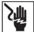
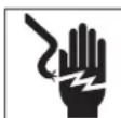
This symbol indicates the risk of electrical shock.

This symbol indicates the risk of machine tipping, causing striking or crushing injuries.

This symbol means do not wear gloves while operating this machine to reduce the risk of entanglement.

This symbol means use support device to resist the threading forces, improve control, and reduce the risk of striking, crushing, and/or other injuries.
General Power Tool Safety Warnings\*
WARNING
Read all safety warnings, instructions, illustrations and specifications provided with this power tool. Failure to follow all instructions listed below may result in electric shock, fire and/or serious injury.
SAVE ALL WARNINGS AND INSTRUCTIONS FOR FUTURE REFERENCE!
The term "power tool" in the warnings refers to your mains-operated (corded) power tool or battery-operated (cordless) power tool.
Work Area Safety
- Keep your work area clean and well lit. Cluttered or dark areas invite accidents.
- Do not operate power tools in explosive atmospheres, such as in the presence of flam mable
liquids, gases, or dust. Power tools create sparks which may ignite the dust or fumes.
- Keep children and bystanders away while operating a power tool. Distractions can cause you to lose control.
Electrical Safety
- Power tool plugs must match the outlet. Never modify the plug in any way. Do not use any adapter plugs with earthed (grounded) power tools. Un modified plugs and matching outlets will reduce risk of electric shock.
- Avoid body contact with earthed or grounded surfaces such as pipes, radiators, ranges and refrigerators. There is an increased risk of electrical shock if your body is earthed or grounded.
-
Do not expose power tools to rain or wet conditions. Water entering a power tool will increase the risk of electrical shock.
-
Do not abuse the cord. Never use the cord for carrying, pulling or unplugging the power tool. Keep cord away from heat, oil, sharp edges or moving parts. Damaged or entangled cords increase the risk of electric shock.
- When operating a power tool outdoors, use an extension cord suitable for outdoor use. Use of a cord suitable for outdoor use reduces the risk of electric shock.
- If operating a power tool in a damp location is unavoidable, use a Ground Fault Circuit Interrupter (GFCI) protected supply. Use of a GFCI reduces the risk of electric shock.
Personal Safety
- Stay alert, watch what you are doing and use common sense when operating a power tool. Do not use a power tool while you are tired or under the influence of drugs, alcohol, or medication. A moment of inattention while operating power tools may result in serious personal injury.
- Use personal protective equipment. Always wear eye protection. Protective equipment such as dust mask, non-skid safety shoes, hard hat, or hearing protection used for appropriate conditions will reduce personal injuries.
- Prevent unintentional starting. Ensure the switch is in the OFF-position before connecting to power source and/or battery pack, picking up or carrying the tool. Carrying power tools with your finger on the switch or energizing power tools that have the switch ON invites accidents.
- Remove any adjusting key or wrench before turning the power tool ON. A wrench or a key left attached to a rotating part of the power tool may result in personal injury.
- Do not overreach. Keep proper footing and balance at all times. This enables better control of the power tool in unexpected situations.
- Dress properly. Do not wear loose clothing or jewel ry. Keep your hair and clothing away from moving parts. Loose clothes, jewelry, or long hair can be caught in moving parts.
- If devices are provided for the connection of dust extraction and collection facilities, ensure these are connected and properly used. Use of dust collection can reduce dust-related hazards.
- Do not let familiarity gained from frequent use of tools allow you to become complacent and ignore
tool safety principles. A careless action can cause severe injury within a fraction of a second.
Power Tool Use and Care
- Do not force the power tool. Use the correct power tool for your application. The correct power tool will do the job better and safer at the rate for which it is designed.
- Do not use power tool if the switch does not turn it ON and OFF. Any power tool that cannot be controlled with the switch is dangerous and must be repaired.
- Disconnect the plug from the power source and/or remove the battery pack, if detachable, from the power tool before making any adjustments, changing accessories, or storing power tools. Such preventive safety measures reduce the risk of starting the power tool accidentally.
- Store idle power tools out of the reach of children and do not allow persons unfamiliar with the power tool or these instructions to operate the power tool. Power tools are dangerous in the hands of untrained users.
- Maintain power tools and accessories. Check for misalignment or binding of moving parts, breakage of parts and any other condition that may affect the power tool's operation. If damaged, have the power tool repaired before use. Many accidents are caused by poorly maintained power tools.
- Keep cutting tools sharp and clean. Properly maintained cutting tools with sharp cutting edges are less likely to bind and are easier to control.
- Use the power tool, accessories and tool bits etc. in accordance with these instructions, taking into account the working conditions and the work to be performed. Use of the power tool for operations different from those intended could result in a hazardous situation.
- Keep handles and grasping surfaces dry, clean and free from oil and grease. Slippery handles and grasping surfaces do not allow for safe handling and control of the tool in unexpected situations.
Service
- Have your power tool serviced by a qualified repair person using only identical replacement parts. This will ensure that the safety of the power tool is maintained.
Specific Safety Information
WARNING
This section contains important safety information that is specific to this tool.
Read these precautions carefully before using the power drives to reduce the risk of electrical shock or serious personal injury.
SAVE THESE INSTRUCTIONS!
Keep this manual with the machine for use by the operator.
Power Drive Safety
- Always use the support device provided with the tool. Loss of control during operation can result in personal injury.
- Keep sleeves and jackets buttoned while operating the tool. Do not reach across the tool or pipe. Clothing can be caught by the pipe or the tool resulting in entanglement.
- Only one person must control the work process and tool operation. Additional people involved in the process may result in unintended operation and personal injury.
- Keep floors dry and free of slippery materials such as oil. Slippery floors invite accidents.
- Do not wear gloves while operating the tool. Do not reach across the tool or pipe. Gloves can be caught by the pipe or the tool resulting in entanglement.
- Always firmly hold the power drive when threading or backing die head off the pipe to resist threading forces, regardless of support device use. This will reduce the risk of striking, crushing and other injuries.
- Follow instructions on proper use of this machine. Do not use for other purposes such as drilling holes or turning winches. Other uses or modifying this machine for other applications may increase the risk of serious injury.
- Do not use this power drive if ON/OFF switch is broken. This switch is a safety device that lets you shut off the motor by releasing the switch.
- Do not use dull or damaged dies. Sharp cutting tools require less torque and the power drive is easier to control.
- Keep handles dry and clean; free from oil and grease. Allows for better control of tool.
- Only use RIDGID die heads with RIDGID Power Drives Other die heads may not fit correctly in the power drive increasing the risk of equipment damage and personal injury.
If you have any question concerning this RIDGProduct:
- Contact your local RIDGID distributor.
- Visit RIDGID.com to find your local RIDGID contact point.
- Contact Ridge Tool Technical Service Department at rttechservices@emerson.com, or in the U.S. and Canada call (800) 519-3456.
Description, Specifications and Standard Equipment
Description
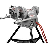
The RIDGID® Model 600-I and 690-I Power Drives are double insulated drives that provide power for threading pipe and conduit. Forward and Reverse rotation can be selected with a slide switch while ON/OFF is controlled by a two-step momentary contact switch.
The 600-I Power Drive is designed to use RIDGID 11-R Drop Head Die Heads ( 18 " - 114 " pipe). The 690-I Power Drive is designed to use RIDGID 11-R Drop Head Die Heads ( 18 " - 2" pipe). An adapter is required for use of the 690-I Power Drive with the 18 " - 114 " sizes. The adapter and the 112 " - 2" sizes are held in the 690-I Power Drive using a Retaining Mechanism.

Figure 1 – Model 600-I Power Drive

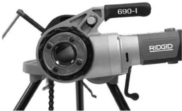
Figure 2 – Model 690-I Power Drive
natural_image
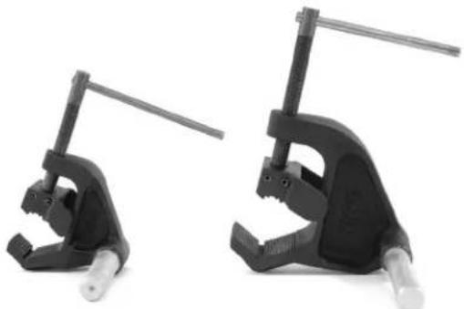
Two black metal clamping tools with adjustable arms and fittings, shown against a white background (no text or symbols visible)Figure 3 – 602/692 Support Arms
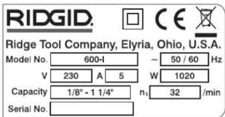
600-I Power Drive and 690-I Power Drive machine serial number plate is located on the bottom of motor housing. The last 4 digits of the serial number indicate the month and year of the manufacture (MMYY).

Figure 4 – Machine Serial Number
Standard Equipment
The Model 600-I/690-I Power Drives come with the following items:
- Power Drive
• 690-I Adapter (690-I only) - Operator's Manual
NOTICE Selection of appropriate materials and installation, joining and forming methods is the responsibility of the system designer and/or installer. Selection of improper materials and methods could cause system failure.
Stainless steel and other corrosion resistant materials can be contaminated during installation, joining and form-
Specifications
| Parameter 600-I Power Drive | 690-I Power Drive | |
| Pipe Threading Capacity | 1a to 114 inch(3 to 32 mm) (3 to 50 mm) | 18 to 2 inch |
| Die Head Holding Ring Spring | Retaining Mechanism (1 | 12-2 inch)Ring Spring ( 18-114 inch) |
| LH Threads Yes Yes | ||
| Support Arm No. 602, No. 601 | No. 692, No. 691 | |
| Adapter Not Required. Used with | 18" through 114" Die Heads. | |
| Motor Type Universal Motor, Single Phase | Universal Motor, Single Phase | |
| Watts | 1270 (120V), 1020 (220-240V) | 1270 (120V), 1020 (220-240V) |
| Voltage/Phase Available | 120V/1PH, 220-240V/1PH | 120V/1PH, 220-240V/1PH |
| Amps | 12A (120V), 5A (220-240V) | 12A (120V), 5A (220-240V) |
| Operating Speed (RPM) | 36 (120V), 32 (220-240V) | 36 (120V), 32 (220-240V) |
| Controls | Forward/Reverse Slide SwitchON/OFF two-step momentary contact switch | Forward/Reverse Slide SwitchON/OFF two-step momentary contact switch |
| Gear Head Die Cast Aluminum | Permanently Greased | Die Cast Aluminum Permanently Greased |
| Length | 20 inch (508 mm) | 24.13 inch (613 mm) |
| Width | 3.75 inch (95 mm) | 4.75 inch (121 mm) |
| Height | 7.5 inch (191 mm) | 8 inch (203 mm) |
| Weight | 12.65 lbs (5.7 kg) | 21.15 lbs (9.6 kg) |
| Sound Pressure ( L_PA )* | 83 dB(A), K=3 | 83 dB(A), K=3 |
| Sound Power ( L_WA )* | 94 dB(A), K=3 | 94 dB(A), K=3 |
| Vibration* | < 2.5 m/s2, K=1.5 | < 2.5 m/s2, K=1.5 |
^a Sound and Vibration measurements are measured in accordance with a standardized test per Standard IEC62841-1.
- Vibration levels may be used for comparison with other tools and for preliminary assessment of exposure.
- Sound and vibration emissions may vary due to your location and specific use of these tools.
- Daily exposure levels for sound and vibration need to be evaluated for each application and appropriate safety measures taken when needed. Evaluation of exposure
levels should consider the time a tool is switched off and not in use. This may significantly reduce the exposure level over the total working period.
ing. This contamination could cause corrosion and premature failure. Careful evaluation of materials and methods for the specific service conditions, including chemical and temperature, should be completed before any installation is attempted.
Pre-Operation Inspection
WARNING


Before each use, inspect power drive and correct any problems to reduce the risk of serious injury from electric shock, crushing injuries and other causes and prevent power drive damage.
- Make sure that the power drive is unplugged.
- Clean any oil, grease or dirt from the power drive and support device, including the handles and controls. This aids inspection and helps prevent the machine or control from slipping from your grip.
-
Inspect the power drive and support arm for the following:
-
Damage or modification to the cord and plug.
- Proper assembly, maintenance and completeness.
- Damaged, misaligned or binding parts.
- Proper operation of two-step momentary contact ON/OFF switch (Figure 5).
- Support arm gripping teeth are clean and in good condition. Teeth can be cleaned with a wire brush.
- Presence and readability of the warning label.
- Any other condition which may prevent safe and normal operation.
If any problems are found, do not use the power drive or support device until the problems have been repaired.
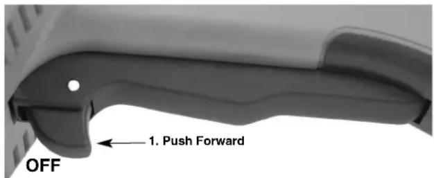
Figure 5A – Two Step Momentary Contact ON/OFF Switch
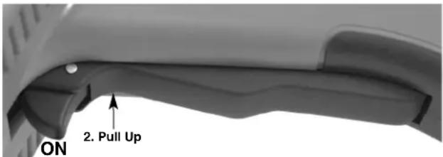
Figure 5B - Two Step Momentary Contact ON/OFF Switch
- Inspect the cutting edges of the dies for wear, deformation, chips or other issues. Dull or damaged cutting tools increase the amount of force required, produce poor quality threads and increase the risk of injury.
- Inspect and maintain any other equipment being used per its instructions to make sure it is functioning properly.
-
Following the Set Up and Operation instructions, check the power drive for proper operation.
-
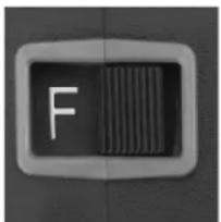
Move the F/R (Forward/Reverse) switch to the F position. Depress and release the ON/OFF switch (Figure 5). Confirm that the power drive rotates in the clockwise direction (see Figure 6) and stops when releasing the switch.
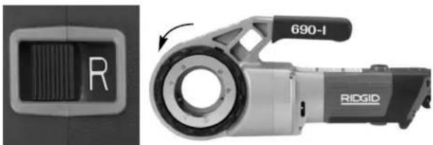
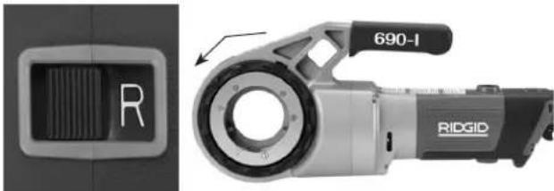
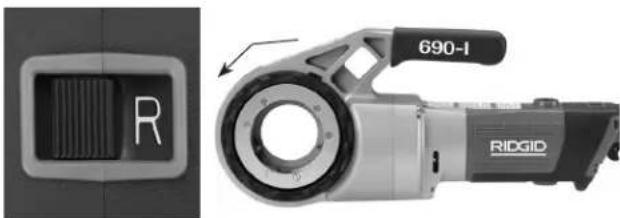
- Repeat the process for the REVERSE (counterclockwise) operation. If the power drive does not rotate in the correct direction, or the ON/OFF switch does not control the machine operation, do not use the machine until it has been repaired.
NOTICE Change position of the F/R slide switch only when the ON/OFF trigger switch is released. Allow the power drive to come to a complete stop before reversing the direction with the F/R slide switch. This will reduce the risk of power drive damage.
- Depress and hold the ON/OFF switch. Inspect the moving parts for misalignment, binding, odd noises or any other unusual conditions. Release the ON/OFF switch. If any unusual conditions are found, do not use the machine until it has been repaired.

natural_image
Ridgid mechanical device with circular housing and handle, no visible text or symbols on bodyFigure 6A - F (FORWARD) (Clockwise) Switch Position
natural_image
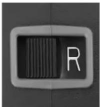
Ridge ID 690-I device shown from front and side, no visible text or symbols on the device itselfFigure 6B - R (REVERSE) (Counter-Clockwise) Switch Position
- Release the ON/OFF switch and with dry hands unplug the machine.
Set-Up and Operation
WARNING


Set up and operate the power drive according to these procedures to reduce the risk of injury from electric shock, entanglement, striking, crushing and other causes, and to help prevent power drive damage.
Use an appropriate support device per these instructions. Sup port devices im prove control and reduce the risk of striking, crushing, and/or other injuries.
When using a support device other than the supplied support arm, the support device must react against the gear housing or fan housing. Support devices contacting the motor housing or handle may damage these parts or increase the risk of injury.
Always firmly hold the power drive when threading or backing die head off the pipe to resist use forces, regardless of support device use. This will reduce the risk of striking, crushing and other injuries.
Do not wear gloves or loose clothing. Keep sleeves and jackets buttoned. Loose clothing can become entangled in rotating parts and cause crushing and striking injuries.
Properly support pipe. This will reduce the risk of falling pipe, tipping and serious injury.
Do not use a power drive without a properly operating ON/OFF switch and F/R slide switch.
One person must control both the work process and the ON/OFF switch. Do not operate with more than one person. In case of entanglement, the operator must be in control of the ON/OFF switch.
-
Check work area for:
-
Adequate lighting.
-
Flammable liquids, vapors or dust that may ignite. If present, do not work in area until sources have been identified and corrected. The power drives are not explosion proof and can cause sparks.
-
Clear, level, stable, dry location for all equipment and operator.
• Good ventilation. Do not use extensively in small, enclosed areas. - Properly wired electrical outlet of the correct voltage. If in doubt, have outlet inspected by a licensed electrician.
-
Clear path to electrical outlet that does not contain any potential sources of damage for the power cord.
-
Inspect the pipe to be threaded and associated fittings and confirm that the selected power drive is a correct tool for the job. See Specifications. Do not use to thread anything other than straight stock.
Equipment for other applications can be found in the Ridge Tool catalog, online at RIDGID.com or by calling Ridge Tool Technical Service in the U.S. and Canada at (800) 519-3456.
- Make sure equipment to be used has been properly inspected.
- Properly prepare the pipe as needed. Make sure the pipe is squarely cut and deburred. Pipe cut at an angle can damage the dies while threading or cause difficulty engaging the die head.
Installing Die Heads
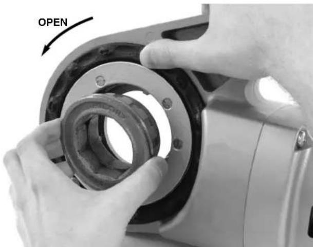
- Installing 1 ^1/2 " or 2" Die Head or Adapter in 690-I:
a. Make sure ON/OFF switch is released and power drive is unplugged.
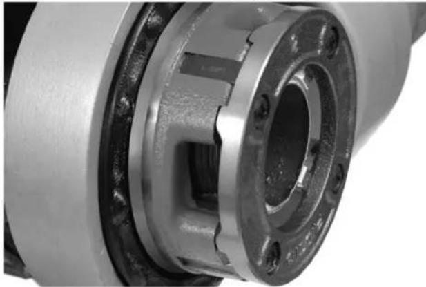
b. Rotate the drive ring counter-clockwise to open the retaining mechanism. Fully insert the die head or adapter (if required) spline end into the power drive (Figure 7).
c. Release the drive ring and confirm that the die head/adapter is secure.
d. Reverse process to remove.
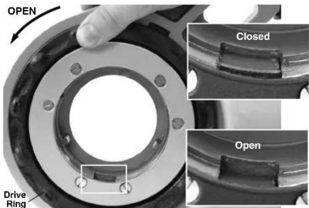
Figure 7 – Retaining Mechanism, Drive Ring in the Open/Closed Position
natural_image
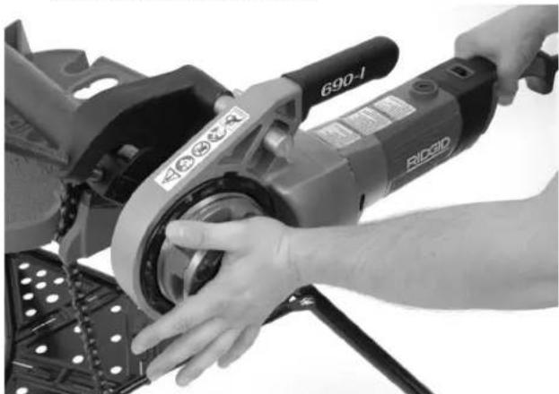
Close-up of hands assembling a mechanical component with a circular opening (no text or symbols visible)Figure 8 – Installing Adapter Into 690-I
- Installing 1 ^1/4 " and smaller Die Heads:
a. Make sure the ON/OFF switch is released and power drive unplugged from the outlet.
b. If needed install the adapter in the 690-I (Figure 8).
c. Squarely insert the octagonal end of the 11-R Die Head into the power drive until secured by the spring ring. On the 600-l, the die head can be inserted into either side of the power drive. With the 690-l, die heads can only be inserted from the adapter side.
d. To remove, pull die head from power drive. If needed, use a soft face hammer or a block of wood to tap the die head out. Do not pound on the die head, this can damage the tool.
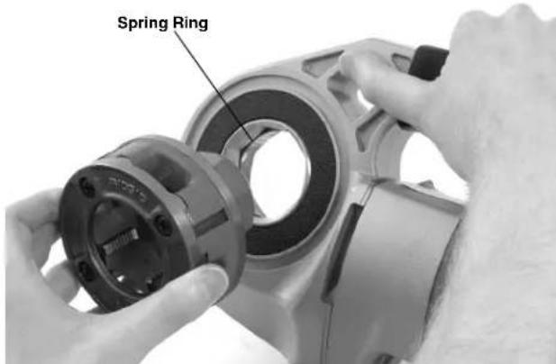
Figure 9 – Installing Die Heads into 600-l Power Drive
- Position the power drive F/R Slide Switch for the desired right or left hand thread. See Figure 10.
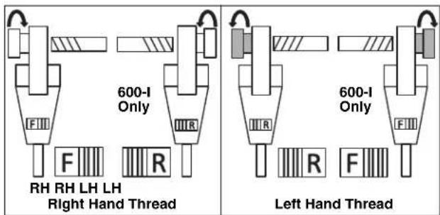
Figure 10 - Slide Switch/Die Head Orientation
- Make sure that pipe to be threaded is stable and secured to prevent tipping during use. Use appropriate pipe stands to support pipe length.
- Check the level of RIDGID Thread Cutting Oil in the RIDGID 418 oiler. Remove the chip tray and confirm that the filter screen is clean and fully submerged in oil. Replace or add oil if necessary. Place the 418 Oiler bucket under the pipe end to be threaded.
Resisting Threading Forces
Using the supplied support arm:
a. Always use the supplied support arm (601 or 602 support arm for 600-l, 691 or 692 support arm for 690-l) unless it can't be used because of space or other constraints. The support arm clamps to the pipe and helps to resist the threading forces.
b. Position the support arm on pipe, so end of support arm aligns with end of pipe and top of support arm is horizontal (Figure 11). This properly places the support arm for threading and prevents threading oil from entering the motor (Figure 12).
c. Make sure that the support arm jaws are squarely aligned with the pipe and securely tighten the support arm.
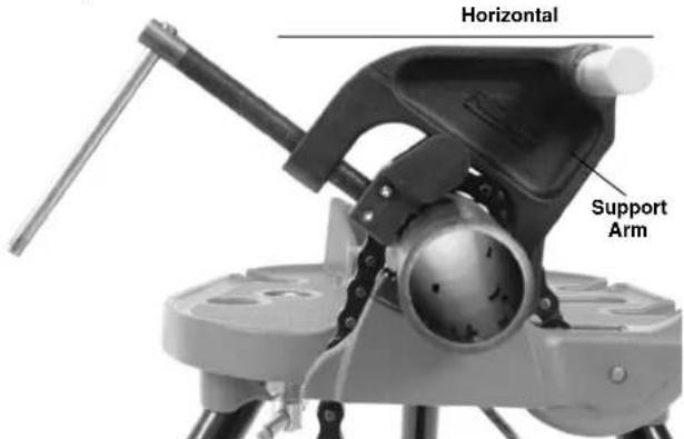
Figure 11A – Positioning the Support Arm
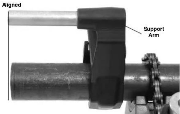
Figure 11B – Positioning the Support Arm
natural_image
RidgID diesel oil rig with tripod base and handle (no visible text or symbols)Figure 12 – Proper Orientation of the Power Drive
When support arm can't be used:
When threading pipe in place or similar application, the support arm may not be able to be used because of space constraints.
a. If possible remove the pipe and thread in a vise. If this cannot be done, other support devices must be used to help resist threading forces, such as placing the power drive gear or fan housing against an adjacent structural member (examples include walls, beams and joists). This requires that the pipe and surroundings be able to withstand the weight of the tool and the threading forces. It may be necessary to add temporary or permanent pipe supports or structural elements.
b. For right hand threads, die head will rotate clockwise (looking at the face of the Die Head). Forces developed by the threading torque will be in the opposite or counter-clockwise direction. Rotation and force will be reversed for left hand threads. Make sure that the support device is set up to properly absorb the threading force.
c. Do not place the power drive motor or handle against adjacent structural members to react threading forces, as this may cause power drive damage.
d. Keep power drive against the structural member and do not place fingers or hands between the power drive and the structural member. When backing die head off thread, always firmly hold the power drive to resist forces from breaking the thread chips. These steps will reduce the risk of striking, crushing and other injuries. The ON/OFF switch can be released at any time to shut OFF the power drive.
Always firmly hold the power drive when threading or backing die head off pipe to resist forces, regardless of support device use. This will reduce the risk of striking, crushing and other injuries. The ON/OFF switch can be released at any time to shut off the power drive.
Threading
-
With dry hands, plug in the power drive.
-
Position the die head over the pipe end and support the power drive as directed in the Resisting Threading Forces Section.
natural_image
Close-up of hands operating a 690-l CNC tool on a mechanical assembly (no visible text or symbols)Figure 13 – Starting the Thread
- Simultaneously actuate the ON/OFF switch and push against the Die Head cover plate with the palm of free hand to start the thread. Do not wear gloves, jewelry or use a rag while pushing on the cover plate – this increases the risk of entanglement and injury. Once the dies engage the pipe, threads will be cut as the dies pull themselves onto the end of the pipe.
Always firmly hold the power drive handle to resist the handle forces. Support devices can slip and allow the
power drive to move. The ON/OFF switch can be released at any time to shut off the power drive.
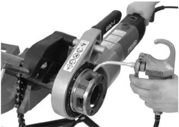
- Stop pushing on cover plate and use oiler to apply a generous quantity of RIDGID Thread Cutting Oil to the area being threaded. This will lower threading torque, improve thread quality and increase die life.
natural_image
Close-up of hands operating a BIDGD CNC machine tool, no visible text or symbols on the device itself.Figure 14 – Threading Pipe
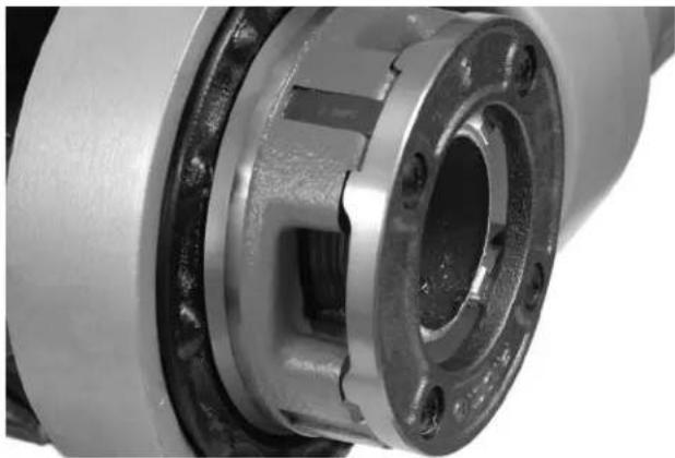
- Depress ON/OFF switch until end of the pipe is even with edge of the dies and release the switch. Let the power drive come to a complete stop.
natural_image
Close-up of a mechanical bearing housing with visible internal components and mounting holes (no text or symbols)Figure 15 – Pipe Even with Edge of Dies
- Reverse the F/R slide switch and actuate the ON/OFF switch to remove Die Head from the threaded pipe. Hold onto the power drive handle firmly to resist the handle forces developed while backing off the Die Head.
NOTICE Change position of the F/R slide switch only when the ON/OFF switch is re leased. Allow the power drive to come to a complete stop before reversing the direction with the F/R slide switch. This will reduce the risk of power drive damage.
- Release the switch and remove the power drive and Die Head from the pipe.
- With dry hands unplug the power drive.
- Wipe oil and debris off the threads and out of the die head, taking care not to cut yourself on sharp debris or edges. Clean up any oil spills in the work area.
Inspecting Threads
- Remove any oil, chips or debris from the thread.
- Visually inspect thread. Threads should be smooth and complete, with good form. If issues such as thread tearing, thin threads, or pipe out-of-roundness are observed, the thread may not seal when made up. Refer to the "Troubleshooting" chart for help in diagnosing these issues.
-
Inspect the size of the thread. The preferred method of checking thread size is with a ring gauge. There are various styles of ring gauges, and their usage may differ from that shown in Figure 16.
-
Screw ring gauge onto the thread hand tight.
- Look at how far the pipe end extends through the ring gage. The end of the pipe should be flush with the side of the gauge plus or minus one turn. If thread does not gauge properly, cut off the thread, adjust the die head and cut another thread. Using a thread that does not gauge properly can cause leaks.
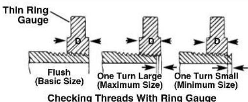
Figure 16 - Checking Thread Size
- If a ring gauge is not available to inspect thread size, it is possible to use a new clean fitting representative of those used on the job to gauge thread size. For 2" and under NPT threads, the threads should be cut to obtain 4 to 5 turns to hand tight engagement with the fitting and for 2" and under BSPT threads it should be 3 turns.
Maintenance Instructions
WARNING
Make sure that the ON/OFF switch is released and the machine is unplugged before performing any maintenance or making any adjustments.
Maintain tool according to these procedures to reduce the risk of injury from electrical shock, entanglement and other causes.
Cleaning
- After each use, empty the threading chips from the 418 Oiler chip tray and wipe out any oil residue.
- Wipe off any oil, grease, chips or dirt from the power drive, including the handles and controls. Clean the 690-l retaining mechanism.
- Wipe off any oil, grease or dirt from the support arm. If required, clean the support arm jaws with a wire brush.
- Remove chips and dirt from die heads.
Changing Dies in 11-R Die Heads
A variety of dies are available for installation in RIDGID 11-R Die Heads. See catalog for availability.
- Remove the four screws ④ from cover ② and remove the cover plate.
- Remove the old dies③ from the die head.
- Insert new dies into slots - numbered edge up. Numbers on the dies must correspond with those on the die head slots. Always replace dies as a set.
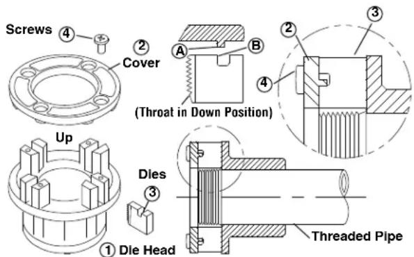
Figure 17 – Installing Dies In Die Head
- Replace the cover plate and tighten the four screws lightly.
- Place die head on already threaded pipe until dies begin to thread. This forces stop on dies ^B outward
against lugsⒶ on cover plate and properly sets the size.
- Tighten the four screws securely. Remove the threaded pipe and make a test cut.
Replacing Brushes in Motor
Check motor brushes every 6 months. Replace when worn to less than 5 / 16'' (8 mm).
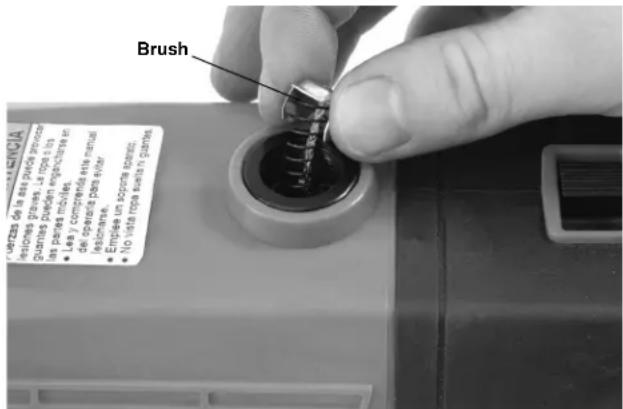
Figure 18 – Brush Installation
- Unplug the machine from power source.
- Unscrew brush caps (Figures 1 and 2). Remove and inspect brushes. Replace when worn to less than 5/16'' (8 mm). Inspect the commutator for wear. If excessively worn, have tool serviced.
- Re-install brushes/install new brushes and securely tighten the brush caps.
- It is best practice to run the unit at idle for 15 minutes in the forward direction followed by 15 minutes in the reverse direction to seat the brushes to the commutator before use.
Accessories
WARNING
To reduce the risk of serious injury, only use accessories specifically designed and recommended for use with the 600-I and 690-I Power Drives such as those listed below. Other Accessories suitable for use with other tools may be hazardous when used with the 600-I and 690-I Power Drives.
600-I and 690-I Power Drive Accessories
| CatalogNo. | Description |
| 45923 | 602 Support Arm |
| 45928 | 692 Support Arm |
| 46668 | 600-I Carrying Case |
| 46673 | 690-I Carrying Case |
| 10883 | 418 Oiler with 1 Gallon Nu-Clear Oil |
| 16703 | 425 ^1/8 " - 2^1/2 " TRISTAND Vise |
| 36273 | 460-6 ^1/8 " - 6" TRISTAND Vise |
Further information on accessories specific to the tool can be found in the RIDGID Catalog and online at RIDGID.com
Machine Storage
WARNING Power Drives must be kept indoors or well covered in rainy weather. Store the machine in a locked area that is out of reach of children and people unfamiliar with the machines. These machines can cause serious injury in the hands of untrained users.
Service and Repair
WARNING
Improper service or repair can make machine unsafe to operate.
The “Maintenance Instructions” will take care of most of the service needs of this machine. Any problems not addressed by this section should only be handled by an authorized RIDGID service technician.
Tool should be taken to a RIDGID Authorized Independent Service Center or returned to the factory.
For information on your nearest RIDGID Authorized Independent Service Center or any service or repair questions:
- Contact your local RIDGID® distributor.
- Visit RIDGID.com to find your local RIDGID contact point.
- Contact Ridge Tool Technical Service Department at rtctechservices@emerson.com or in the U.S. and Canada call (800) 519-3456.
Threading Oil
For information concerning RIDGID® Thread Cutting Oil use and handling, refer to the labels on the container and Material Safety Data Sheet (MSDS). MSDS is available at RIDGID.com or by contacting Ridge Tool Technical Service Department at (800) 519-3456 in U.S. and Canada or rttechservices@emerson.com.
Disposal
Parts of the Power Drives contain valuable materials and can be recycled. There are companies that specialize in recycling that may be found locally. Dispose of the components in compliance with all applicable regulations. Contact your local waste management authority for more information.
For EC Countries: Do not dispose of electrical equipment with household waste!
According to the European Guideline 2012/19/- EU for Waste Electrical and Electronic Equipment and its implementation into national legislation, electrical equipment that is no
longer usable must be collected separately and disposed of in an environmentally correct manner.
Troubleshooting
| SYMPTOM POSSIBLE REASONS SOLUTION | ||
| Machine will not run. | Brushes do not touch armature. | Check brushes, replace if worn. |
| Machine not able to thread. | Dull dies. | Replace dies. |
| Overload due to torn or out-of-round threads. | See possible reasons below. | |
| Poor quality or insufficient thread cutting oil. | Use RIDGID® Thread Cutting Oil in adequate quantity. | |
| Insufficient line voltage. | Check power supply voltage. | |
| Sparks forming at motor commutator. | Insufficient contact between brushes and commu-tator. | Tighten the brush caps to make sure brushes are pressed firmly onto commutator. |
| Brushes do not touch commutator properly. | Replace worn brushes and or armature. | |
| Brushes of different manufacture. | Only use RIDGID® brushes. | |
| New brushes. | Seat the brushes by running the unit at idle for 15 minutes in Forward and Reverse. | |
| Die head does not start threading. | Die head not square with end of pipe. | Push against die head cover plate to start thread. |
| Engagement force not properly applied to the die head. | Apply engagement force through the center line of the pipe. | |
| Pipe end not squarely cut. | Cut the pipe end squarely. | |
| Dull or broken dies. | Replace dies. | |
| Machine running in wrong direction. | Check position of the F/R Slide Switch. | |
| Dies set improperly in the die head. | Ensure chasers are set outward against the cover plate lugs. | |
| Torn threads. | Damaged, chipped or worn out dies. | Replace dies. |
| Improper or insufficient thread cutting oil. | Only use RIDGID® Thread Cutting Oil in adequate quantity. | |
| Incorrect type of die for material. | Select high-speed, stainless steel , or alloy dies that are suitable for the application. | |
| Poor pipe material/quality. | Use higher quality pipe. | |
| Out-of-round or crushed threads. | Pipe wall thickness too thin. | Use schedule 40 or heavier wall thickness. |
| Support device turns while threading. | Support arm jaws dirty. | Clean with wire brush. |
| Support arm not aligned properly. | Align support arm squarely with the pipe. | |
| Support arm not tight. | Tighten feedscrew. | |
| Thin Threads. | Dies not placed in proper order. | Place dies in proper die head slot. |
natural_image
Two R1DGID power tool designs shown from different angles (600-I and 690-I), no text or symbols on the devices themselves.! AVERTISSEMENT !
natural_image
Two black metal clamping tools with adjustable arms and fittings (no text or symbols visible)natural_image
Exterior view of a modern office building (no signage)natural_image
Close-up of a rectangular device with a black panel and a white letter 'R' on the side (no additional text or symbols)
natural_image
Ridge ID 690-I mechanical device with circular housing and handle (no visible text or symbols beyond branding)natural_image
Ridgid diesel drilling rig with tripod base (no visible text or symbols)natural_image
Close-up of hands operating a 690-l CNC machine tool on a metal bracket (no visible text or symbols)Figure 13 – Entamer le filetage
natural_image
Close-up of a person using a BIRDGIG tool to adjust a mechanical component (no visible text or symbols)Figure 14 – Filetage du tuyau
natural_image
Close-up of a mechanical bearing housing with internal components and mounting holes (no visible text or symbols)natural_image
Two R1DGID power tool designs shown from different angles (600-I and 690-I), no text or symbols on the devices themselves.
ADVERTENCIA
natural_image
Two black metal clamping tools with adjustable arms and fittings, shown against a white background (no text or symbols visible)natural_image
Ridgid industrial tool with circular head and handle, no visible text or symbols on bodynatural_image
Close-up of a rectangular button with a white letter 'R' on the left side, no additional text or symbols visible.
natural_image
Exterior view of a modern office building (no signage)natural_image
Ridge ID 690-1 diesel oil rig with tripod base (no visible text or symbols beyond branding)natural_image
Close-up of hands operating a 690-l angle grinder on a metal cutting board (no visible text or symbols)natural_image
Close-up of a person using a G302-1 electric drill press machine with a tool, no visible text or symbols on the device itself.natural_image
Close-up of a mechanical bearing housing with visible internal components and mounting holes (no text or symbols)natural_image
Two R1DGID CNC machines with labeled end caps (600-I and 690-I), shown against a plain background.WARNING!
natural_image
Two black metal clamping tools with adjustable arms and fittings, shown against a white background (no text or symbols visible)natural_image
Rigid mechanical tool with labeled part 690-I, no visible text or symbols beyond brandingnatural_image
Rigid mechanical device with no visible text or symbols on body, featuring part number 690-1 and brand name Rigidnatural_image
Ridgid hydraulic tool with tripod base and handle (no visible text or symbols on body)natural_image
Close-up of hands operating a 690-l刨机 (RiDio) with a metal base, no visible text or symbols on the tool itself.natural_image
Close-up of a person using a BIDIG power tool on a mechanical assembly (no visible text or symbols)natural_image
Close-up of a mechanical bearing housing with visible internal components and mounting holes (no text or symbols)natural_image
Two R1DGID power tools with black handles and labeled designs (600-I and 690-I), shown against a plain background.
WAARSCHUWING!
natural_image
Two black metal chain clamps with adjustable arms and plastic ends, shown against a white background (no text or symbols visible)Figuur 3 – 602/692 steunarmen
natural_image
Exterior view of a 690-I RIDGID robotic device with internal components (no text or symbols on the device itself)Figuur 6A – Schakelaarstand F (VOORUIT) (rechtsom)

natural_image
Exterior view of a 690-I RIDGID robotic device with a labeled control panel (no text or symbols on the device itself)Figuur 6B – Schakelaarstand R (ACHTERUIT) (linksom)
- Adequate verlichting.
natural_image
Close-up of hands assembling a mechanical component with a circular housing and bolt holes (no text or symbols visible)Figuur 8 – De adapter in de 690-I installeren
natural_image
Ridgid drilling rig with tripod base and handle (no visible text or symbols)natural_image
Close-up of hands operating a 690-l angle grinder on a metal cutting board (no visible text or symbols)natural_image
Close-up of hands operating a BICGID electric drill press machine (no visible text or symbols)natural_image
Close-up of a mechanical bearing housing with visible internal components and mounting holes (no text or symbols)natural_image
Two RIDGID power tool designs shown from different angles (600-I and 690-I), no text or symbols on the devices themselves.AVVERTENZA!
natural_image
Two black metal clamping tools with adjustable arms and shafts, shown against a white background (no text or symbols visible)natural_image
Exterior view of a 690-I RIDGID robotic device with internal components (no text or symbols on the device itself)natural_image
Exterior view of a 690-I RIGID mechanical device with a side panel showing a labeled component (R), no text or symbols on the device itself.natural_image
Five black-and-white safety symbols: circular warning sign, hand gesture, no glove, gear mechanism, and mechanical device (no text or labels)natural_image
Ridgid drilling rig with tripod base and handle (no visible text or symbols)natural_image
Close-up of hands operating a 690-1 precision power tool on a metal workpiece (no visible text or symbols)natural_image
Close-up of a person using a B2001 electric drill press machine with a tool, no visible text or symbols on the device itself.natural_image
Close-up of a mechanical bearing housing with visible internal components and mounting holes (no text or symbols)natural_image
Two R1DGID CNC machines with labeled end caps (600-I and 690-I), shown against a plain background.! AVISO!
natural_image
Two black metal clamping tools with adjustable arms and fittings, shown against a white background (no text or symbols visible)Figura 3 – Braços de suporte 602/692
Figura 4 – Número de série da máquina
natural_image
Exterior view of a modern office building (no signage)natural_image
Close-up of a rectangular button with a white letter 'R' on the right side, no additional text or symbols visible.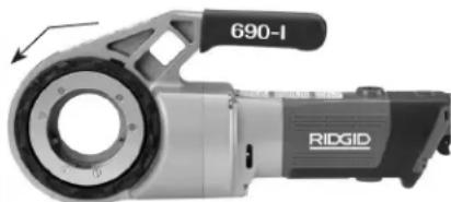
natural_image
Exterior view of a modern office building (no signage)natural_image
RidgizD hydraulic tool with tripod base and labeled part (no text beyond branding)natural_image
Close-up of hands operating a 690-lit R300 electric drill press on a metal workbench (no visible text or symbols)Figura 13 – Iniciar a rosca
natural_image
Close-up of hands operating a BIRDGID electric drill press machine (no visible text or symbols)natural_image
Close-up of a mechanical bearing housing with visible internal components and mounting holes (no text or symbols)natural_image
Two RIDGID power tool designs shown from different angles (600-I and 690-I), no text or symbols on the devices themselves.WARNING!
natural_image
Two black metal clamping tools with adjustable arms and fittings, shown against a white background (no text or symbols visible)Figur 4 – Maskinens serienummer
Standardutrustning
natural_image
Exterior view of a 690-I RIDG ID scanner device (no text or symbols on the device itself)Figur 6A – F-läget (FORWARD/FRAMÅT) (medurs)
natural_image
Exterior view of a 690-I RIDGID robotic device with labeled ports (no text beyond branding)Figur 6B – R-läget (REVERSE/BACK) (moturs)
natural_image
Ridg ID industrial drilling rig with tripod base (no visible text or symbols)Figur 12 - Drivenhetens korrekta orientering
natural_image
Close-up of hands operating a 690-1 precision power tool on a metal workpiece (no visible text or symbols)Figur 13 – Starta gängan
natural_image
Close-up of hands operating a BIDGID CNC machine tool, no visible text or symbols on the device itself.Figur 14 – Rörgängning
natural_image
Close-up of a mechanical bearing housing with visible internal components and bolt holes (no text or symbols)natural_image
Two R1DGID CNC machines with labeled end caps (600-I and 690-I), shown against a plain background.ADVARSEL!
natural_image
Two black metal clamping tools with adjustable arms and joints, shown against a white background (no text or symbols visible)Figur 3 – 602/692 støttearme
Figur 4 – Maskinens serienummer
Standardudstyr
natural_image
Exterior view of a 690-1 RIDGIO electric shaver with internal components (no text or symbols on body)Figur 6A – Kontaktstilling F (FORWARD (FREMADGÅ-ENDE)) (med uret)
natural_image
Exterior view of a 690-1 RRDGID mechanical device with internal components (no text or symbols on the device itself)Figur 6B – Kontaktstilling R (REVERSE (TILBAGEGÅENDE)) (mod uret)
natural_image
Five black-and-white safety symbols: circular warning circle, hand gesture, no glove, gear, and mechanical device (no text or labels)natural_image
RidgizD irrigation tool with tripod base and labeled part (no text beyond branding)natural_image
Close-up of hands operating a 690-lift RISCO power tool on a metal bracket (no visible text or symbols)natural_image
Close-up of a person using a B200 electric drill center machine with a tool, no visible text or symbols on the equipment.natural_image
Close-up of a mechanical bearing housing with visible internal components and mounting holes (no text or symbols)natural_image
Two RIDGID power tool designs shown from different angles (600-I and 690-I), no text or symbols on the devices themselves.ADVARSEL!
natural_image
Two black metal clamping tools with adjustable arms and fittings, shown against a white background (no text or symbols visible)Figur 4 – maskinserienummer
Standardutstyr
Modellen 600-1/690-1 håndgjengemaskin leveres med følgen-de artikler:
• Håndgjengemaskin
• 690-1-adapter (kun 690-1)
- Bruksanvisning
natural_image
Exterior view of a 690-I RIDGID robotic device with a labeled component (no text or symbols on the device itself)natural_image
Exterior view of a 690-I RIDGID robotic device with a labeled sensor (no text or symbols on the device itself)Figur 6B - R (REVERSE, bakover) (mot klokken) bryterstilling
natural_image
Five black-and-white safety symbols: circular head, hand gesture, crossed hand, gear, and mechanical device (no text or labels)natural_image
RidgizD electric drill press with tripod base (no visible text or symbols)Figur 12 – korrekt orientering av håndgjengemaskinen
natural_image
Close-up of hands operating a 690-l刨机 (RiD50) with a metal workpiece, no visible text or symbols on the device itself.natural_image
Close-up of hands operating a BIDGID CNC machine tool, no visible text or symbols on the device itself.natural_image
Close-up of a mechanical bearing housing with visible internal components and mounting holes (no text or symbols)natural_image
Two RIDGID power tool designs shown from different angles (600-I and 690-I), no text or symbols on the devices themselves.VAROITUS!
natural_image
Two black metal chain clamps with adjustable arms and plastic ends, shown against a white background (no text or symbols visible)natural_image
Exterior view of a 690-1 RIDGID robotic device with internal components (no text or symbols on main body)natural_image
Exterior view of a 690-I RIDGID robotic device (no text or symbols on the device itself)natural_image
Ridge ID 690-1 diesel oil rig with tripod base (no visible text or symbols beyond branding)natural_image
Close-up of hands operating a 690-l CNC machine tool on a metal bracket (no visible text or symbols)natural_image
Close-up of hands operating a BIDGD electric drill press machine (no visible text or symbols)natural_image
Close-up of a mechanical bearing housing with visible internal components and bolt holes (no text or symbols)natural_image
Two RIDGID power tool designs shown from different angles (600-I and 690-I), no text or symbols on the devices themselves.OSTRZEŻENIE!
natural_image
Two black metal clamping tools with adjustable arms and fittings, shown against a white background (no text or symbols visible)natural_image
Exterior view of a R1DGID robotic device with labeled part '690-I', showing internal structure and mounting bracket (no readable text beyond branding)natural_image
Exterior view of a 690-lift RIDGID robotic device with internal components (no text or symbols on the device itself)natural_image
Ridge ID 690-1 water drill press with tripod base (no visible text or symbols beyond branding)natural_image
Close-up of hands operating a 690-lift RIC30 power tool on a metal cutting board (no visible text or symbols)natural_image
Close-up of hands operating a BICGID electric drill press machine with visible branding and warning symbols (no text or labels on the device itself)natural_image
Close-up of a mechanical bearing housing with visible internal components and bolt holes (no text or symbols)natural_image
Two RIDGID power tool designs shown from different angles (600-I and 690-I), no text or symbols on the devices themselves.⚠️ VAROVÁNÍ!
natural_image
Two black metal clamping tools with adjustable arms and shafts, shown against a white background (no text or symbols visible)natural_image
Exterior view of a modern office building (no signage)natural_image
Exterior view of a 690-I RIDGID robotic device with internal components (no text or symbols on the device itself)natural_image
Five black-and-white safety symbols: circular warning sign, hand gesture, no glove, gear mechanism, and mechanical device (no text or labels)natural_image
Ridgid drilling rig with tripod base and handle (no visible text or symbols)natural_image
Close-up of hands operating a 690-1 precision power tool on a metal bracket (no visible text or symbols)natural_image
Close-up of a person using a BIDGD electric drill press machine, no visible text or symbols on the device itself.natural_image
Close-up of a mechanical bearing housing with internal components and mounting holes (no visible text or symbols)natural_image
Two RIDGID power tool designs shown from different angles (600-I and 690-I), no text or symbols on the devices themselves.VÝSTRAHA!
TIETO POKYNY USCHOVAJTE!
Tento návod uchovávajte pri stroji pre potreby operátora.
natural_image
Two black metal clamping tools with adjustable arms and fittings (no text or symbols visible)natural_image
Exterior view of a 690-I RIDGID robotic device (no text or symbols on the device itself)natural_image
Exterior view of a 690-I RIDGID robotic device with labeled ports (no text beyond branding)natural_image
Ridgid drilling rig with tripod base and handle (no visible text or symbols)natural_image
Close-up of hands operating a 690-1 precision tool on a metal cutting board (no visible text or symbols)natural_image
Close-up of hands operating a BICSID electric drill press machine (no visible text or symbols)natural_image
Close-up of a mechanical bearing housing with visible internal components and mounting holes (no text or symbols)natural_image
Two RIDGID power tool designs shown from different angles (600-I and 690-I), no text or symbols on the devices themselves.AVERTIZARE!
natural_image
Two black metal clamping tools with adjustable arms and fittings, shown against a white background (no text or symbols visible)Figura 3 – 602/692 Brațe reazem
Figura 4 – Seria maşinii
natural_image
Exterior view of a modern office building (no signage)natural_image
Rigid mechanical device with labeled part '690-I' and model number 'RIDGID', no readable text beyond brandingnatural_image
RidgID hydraulic tool with tripod base and handle (no visible text or symbols on body)natural_image
Close-up of hands operating a 690-l刨床 tool on a metal workpiece (no visible text or symbols)Figura 13 – Pornire filetare
natural_image
Close-up of a person using a Rigido electric drill press machine, no visible text or symbols on the device itself.natural_image
Close-up of a mechanical bearing housing with internal components and mounting holes (no visible text or symbols)Figura 15 – Teava la nivel cu marginea filierelor
natural_image
Two R1DGID CNC machines with labeled end caps (600-I and 690-I), shown against a plain background.VIGYÁZAT!
natural_image
Two black metal clamping tools with adjustable arms and shafts, shown against a white background (no text or symbols visible)natural_image
Exterior view of a modern office building (no signage)natural_image
Rigid mechanical tool with labeled part 690-1, no visible text or symbols beyond brandingnatural_image
Ridge Lid (690-1) mechanical tool with tripod base and handle (no visible text or symbols beyond branding)natural_image
Close-up of hands operating a 690-lit R300 electric drill press on a metal workbench (no visible text or symbols)natural_image
Close-up of hands operating a BICGID CNC machine tool, no visible text or symbols on the device itself.natural_image
Close-up of a mechanical bearing housing with visible internal components and mounting holes (no text or symbols)natural_image
Two RIDGID power tool designs shown from different angles (600-I and 690-I), no text or symbols on the devices themselves.
ΠΡΟΕΙΔΟΠΟΙΗΣΗ!
natural_image
Two black metal clamping tools with adjustable arms and fittings, shown against a white background (no text or symbols visible)natural_image
Exterior view of a modern office building (no signage)natural_image
Close-up of a rectangular button labeled 'R' with a striped pattern on the left side (no other text or symbols visible)
natural_image
Rigid mechanical device with no visible text or symbols on body, featuring part number 690-1 and brand name RIDGID (no readable text beyond branding)natural_image
Ridge ID 690-1 diesel oil rig with tripod base (no visible text or symbols beyond branding)natural_image
Close-up of hands operating a 690-1 precision power tool on a metal workbench (no visible text or symbols)natural_image
Close-up of hands operating a BicciD tool on a mechanical assembly (no visible text or symbols)natural_image
Close-up of a mechanical bearing housing with flanges and central bore (no visible text or symbols)natural_image
Two RIDGID power tool designs shown from different angles (600-I and 690-I), no text or symbols on the devices themselves.UPOZORENJE!
natural_image
Two black metal clamping tools with adjustable arms and shafts, shown against a white background (no text or symbols visible)natural_image
Exterior view of a 690-1 RIDGID robotic device with internal components (no text or symbols on the device itself)natural_image
Exterior view of a 690-I RIGID robotic device (no text or symbols on the device itself)natural_image
Five black-and-white safety icons: circular head, hand gesture, crossed-out hand, gear with teeth, and mechanical device (no text or symbols)natural_image
Ridgid diesel drilling rig with tripod base and handle (no visible text or symbols)natural_image
Close-up of hands operating a 690-l刨床 tool on a metal workpiece (no visible text or symbols)Slika 13 – Početak nareza
- Kako biste započeli narezivanje istovremeno pritisnite prekidač UKLJUČENO/ISKLJUČENO i dlanom slobodne ruke pritisnite pokrovnu ploču narezne glave. Nemojte nositi rukavice niti nakit ili koristiti krpu dok pritiskujete pokrovnu ploču - to povećava opasnost od zapetljavanja ili ozljede. Kad noževi počnu raditi na cijevi narezi će se rezati kako se noževi naslanjaju na kraj cijevi.
natural_image
Close-up of hands operating a BPGD1 CNC machine tool, no visible text or symbols on the device itself.Figure 14 – Narezivanje cijevi
- Ponovno pritisnite prekidač UKLJUČENO/ISKLJUČENO dok se cijev ne poravna s rubovima noževa i otpustite prekidač. Pustite alat da se potpuno zaustavi.
natural_image
Close-up of a mechanical bearing housing with visible internal components and bolt holes (no text or symbols)Slika 15 – Cijev poravnata s rubom noževa
natural_image
Two R1DGID power tools with black handles and labeled designs (600-I and 690-I), shown against a plain background.OPOZORILO!
natural_image
Two black metal clamping tools with adjustable arms and fittings, shown against a white background (no text or symbols visible)natural_image
Exterior view of a 690-1 RIDG ID scanner device (no text or symbols on the device itself)natural_image
Exterior view of a 690-I RIDGID robotic device with labeled ports and a circular control dial (no text beyond labels)Slika 6B – Položaj stikala R (VZVRATNO) (levo)
- Sprostite stikalo za vklop/izklop in s suhimi rokami odklopite napravo.
Priprava in uporaba
OPOZORILO

natural_image
Five black-and-white safety symbols: circular head, hand gesture, no glove, gear mechanism, and mechanical device (no text or labels)natural_image
Ridge ID 690-1 precision drilling rig with tripod base (no visible text or symbols beyond branding)natural_image
Close-up of hands operating a 690-lift power tool on a metal bracket (no visible text or symbols)Slika 13 – Začenjanje vrezovanja
- Hkrati vklopite stikalo za vklop/izklop in potisnite proti pokrivni plošei rezalne glave z dlanjo proste roke, da začnete navoj. Med pritiskanjem proti pokrivni plošei ne nosite rokavic in nakita ter ne uporabite krpe – s tem se poveđa tveganje zapletanja in telesnih poškodb. Ko rezalni nastavki primejo za cev se navoj izreže, ko se rezalni nastavki potegnejo na konec cevi.
natural_image
Close-up of hands operating a BICSID electric drill press machine (no visible text or symbols)natural_image
Close-up of a mechanical bearing housing with internal components and mounting holes (no visible text or symbols)Slika 15 – Cev je poravnana z robom rezalnih nastavkov
natural_image
Two RIDGID power tool designs shown from different angles (600-I and 690-I), no text or symbols on the devices themselves.⚠ UPOZORENJE!
Pažljivo pročitajte uputstva pre korišćenja ovog alata. Nepoznavanje i nepridržavanje uputstava iz ovog priručnika može imati za posledicu strujni udar, požar i/ili teške telesne povrede.
natural_image
Two black metal clamping tools with adjustable arms and fittings, shown against a white background (no text or symbols visible)Slika 3 – 602/692 Potporne stege
Pločica sa serijskim brojem mašine kod električne nareznice 600-1 i električne nareznice 690-1 nalazi se na donjem delu kućišta motora. Poslednje 4 cifre u serijskom broju ukazuju na mesec i godinu proizvodnje (MMGG).
Slika 4 – Serijski broj mašine
Standardna oprema
natural_image
Exterior view of a modern office building (no signage)Slika 6A – F (FORWARD/napred/) (u smeru kazaljke na satu) položaj prekidača
natural_image
Close-up of a rectangular button labeled 'R' with a striped pattern inside, no readable text or symbols beyond the letter.
natural_image
Rigid mechanical tool with labeled part '690-I' and model number 'RIDGID', no readable text beyond brandingSlika 6B – R (REVERSE /obrnuto/) (suprotno od kazaljke na satu) položaj prekidača
- Pustite prekidač ON/OFF i suvim rukama isključite mašinu iz struje.
Podešavanje i rad
⚠ UPOZORENJE


Podesite električnu nareznicu i koristite je u skladu sa ovim procedurama da biste smanjili opasnost od povređivanja usled strujnog udara, upetljavanja, udaranja, nagnječenja i drugih uzroka, i da ne bi došlo do oštećenja same električne nareznice.
Koristite odgovarajuću pomoćnu alatku u skladu sa ovim uputstvima. Pomoćna alatka poboljšava kontrolu i smanjuje opasnost od udaranja, nagnječenja i/ili drugih povreda.
Kada ne koristite priloženu potpornu stegu već neku drugu pomoćnu alatku, ta pomoćna alatka mora da se oslanja na kućište zupčanika ili kućište ventilatora. Pomoćne alatke koje dodiruju kućište motora ili ručku mogu da ih oštete ili povećaju opasnost od povrede.
Uvek čvrsto držite električnu nareznicu tokom narezivanja ili naslanjanja narezne glave na cev da biste se oduprli silama, bez obzira na to što koristite pomoćnu alatku. Time ćete smanjiti opasnost od udaranja, nagnječenja i drugih povreda.
natural_image
RidgID hydraulic tool with tripod base and handle (no visible text or symbols)Slika 12 – Ispravan položaj električne nareznice
Kada potporna stega ne može da se koristi:
Kada treba narezati fiksiranu cev ili koristiti nareznicu u slične svrhe, potporna stega možda neće moći da se koristi zbog ograničenog prostora.
natural_image
Close-up of hands operating a 690-1 precision power tool on a metal bracket (no visible text or symbols)Slika 13 – Početak narezivanja
- Istovremeno aktivirajte ON/OFF prekidač i dlanom slobodne ruke pritisnite poklopac narezne glave da biste počeli s narezivanjem. Dok gurate poklopac nemojte da nosite rukavice ili nakit i nemojte da koristite krpu jer se time povećava opasnost od upetljavanja i povređivanja. Kada nareznica dotakne cev, navoji će početi da se narezuju dok se nareznica bude navlačila na kraj cevi.
Uvek čvrsto držite ručku električne nareznice da biste se oduprli silama koje deluju na ručku. Pomoćne alatke mogu da skliznu i omoguće električnoj nareznici da se pomeri. Prekidač ON/OFF možete biti pušten bilo kada da bi se isključila električna nareznica.
- Prestanite da pritiskate poklopac i podmazivačem nanesite veliku količinu RIDGID ulja za narezivanje navoja na područje koje se narezuje. Time će se smanjiti obrtni momenat narezivanja, poboljšati kvalitet navoja i produžiti radni vek nareznice.

natural_image
Close-up of hands operating a BPGD1 CNC machine tool, no visible text or symbols on the device itself.Slika 14 – Narezivanje cevi
- Pritisnite i držite prekidač ON/OFF sve dok se kraj cevi ne poravna sa ivicom nareznica i zatim pustite prekidač. Ostavite električnu nareznicu da se potpuno zaustavi.

natural_image
Close-up of a mechanical bearing housing with visible internal components and bolt holes (no text or symbols)natural_image
Two R1DGID CNC machines with labeled end caps (600-I and 690-I), shown against a plain background.ВНИМАНИЕ!
natural_image
Two black metal clamping tools with adjustable arms and plastic ends, shown against a white background (no text or symbols visible)natural_image
Exterior view of a modern office building (no signage)natural_image
Close-up of a rectangular electronic component with a striped internal bar and the letter 'R' in the center (no readable text or symbols beyond the label)
natural_image
Close-up of a gray and black RIGID mechanical tool with no visible text or symbols on its body (text is part of the device label)natural_image
Ridgid diesel oil rig with tripod base and handle (no visible text or symbols)natural_image
Close-up of hands operating a 690-1 precision power tool on a metal bracket (no visible text or symbols)natural_image
Close-up of hands operating a Bicoid drilling machine with a hook, no visible text or symbols on the equipment.natural_image
Close-up of a mechanical bearing housing with visible internal components and mounting holes (no text or symbols)natural_image
Two RIDGID power tool designs shown from different angles (600-I and 690-I), no text or symbols on the devices themselves.! UYARI!
natural_image
Two black metal clamping tools with adjustable arms and fittings, shown against a white background (no text or symbols visible)natural_image
Exterior view of a 690-I RIDGID robotic device (no text or symbols on the device itself)natural_image
Exterior view of a 690-I RIDGIO robotic device with a labeled component (no text or symbols on the device itself)natural_image
Five black-and-white safety icons: no helmet, hand gesture, no tool, gear, and wheel (no text or symbols)natural_image
Ridgid drilling rig with tripod base and handle (no visible text or symbols)natural_image
Close-up of hands operating a 690-l刨机 (RiD20) on a metal workbench, no visible text or symbols on the tool itself.natural_image
Close-up of hands operating a B320-1 CNC tool with a hook handle, no visible text or symbols on the device itself.natural_image
Close-up of a mechanical bearing housing with visible internal components and mounting holes (no text or symbols)natural_image
Two R1DGID CNC machines with labeled end caps (600-I and 690-I), shown against a plain background.ECKEPTY!
natural_image
Two black metal clamping tools with adjustable arms and fittings, shown against a white background (no text or symbols visible)natural_image
Ridgeid mechanical device with labeled part 690-I, no visible text or symbols beyond brandingnatural_image
Exterior view of a modern office building (no signage)natural_image
Ridge ID 690-1 diesel oil rig with tripod base (no visible text or symbols beyond branding)natural_image
Close-up of hands operating a 690-1 precision power tool on a metal bracket (no visible text or symbols)natural_image
Close-up of hands operating a Bicgid electric drill press machine (no visible text or symbols)natural_image
Close-up of a mechanical bearing housing with visible internal components and mounting holes (no text or symbols)RIDGE TOOL COMPANY Ridge Tool Europe NV (RIDGID)
400 Clark Street
Elyria, Ohio 44035-6001
U.S.A.
EC DECLARATION OF CONFORMITY
We declare that the machines listed above, when used in accordance with the operator's manual, meet the relevant requirements of the Directives and Standards listed below.
DÉCLARATION DE CONFORMITÉ CE
DEKLARACJA ZGODNOŚCI WE
Conforms to UL 62841-1/UL 62841-2-9
Certified to CSA C22.2#62841-1/CSA C22.2#62841-2-9

Signature: Vindork
Qualification: V.P. Engineering
Date: 04/01/2020

For Warranty Information for your World Region visit RIDGID.com
Ridge Tool Europe N.V. (RIDGID)
© 2013, 2020, RIDGID, Inc.
Printed 06/20 999-999-476.09 The Emerson logo and RIDGID logo are registered trademarks of Emerson Electric Co. or RIDGID, Inc. in the U.S. and other countries. EC44604 REV. F All other trademarks belong to their respective holders.