
975 - Power tool RIDGID - Free user manual and instructions
Find the device manual for free 975 RIDGID in PDF.

| Product Type | Mixed Roll Groover |
| Brand | RIDGID |
| Model | 975 |
| Steel Pipe Capacity | Diameter 1 1/4" to 6", schedules 10 and 40 |
| Copper Pipe Capacity | Diameter 2" to 4" types K, L, M, DWV (with roll change) |
| Other Materials | Aluminum, PVC, stainless steel (schedules 10 and 40) |
| Weight | 27.6 lb (≈ 12.5 kg) |
| Feed Mechanism | Feed screw with 1/2" ratchet wrench |
| Compatible Drive Systems | RIDGID 300 (38/57 rpm), RIDGID 300 Compact (with adapter) |
| Manual Operation | Yes, on job site with ratchet wrench |
| Depth Adjustment | Graduated depth gauge built-in |
| Maintenance | Monthly lubrication, regular cleaning of hubs |
| Roll Replacement Interval | According to wear, using specific RIDGID rolls |
| Standard Equipment | Grooving/drive rolls, ratchet wrench with lock, extension, tubular supports, depth gauge |
| Optional Accessories | Copper rolls, 300 Compact adapter, circumference tape, portable vise |
| Safety | Wear PPE (goggles, shoes, hard hat), do not wear loose clothing, use foot pedal |
| Warranty | RIDGID Lifetime Warranty |
| After-Sales Service | Ridge Tool Company, RIDGID authorized repair centers |
| Grooving Standard | AWWA C606-06 (for steel 2" to 6") |
| Intended Use | Grooving pipes for mechanical couplings, job site or light shop use |
Frequently Asked Questions - 975 RIDGID
User questions about 975 RIDGID
0 question about this device. Answer the ones you know or ask your own.
Ask a new question about this device
Download the instructions for your Power tool in PDF format for free! Find your manual 975 - RIDGID and take your electronic device back in hand. On this page are published all the documents necessary for the use of your device. 975 by RIDGID.
USER MANUAL 975 RIDGID
natural_image
Close-up of a metallic mechanical component with no visible text or symbols on the body itself.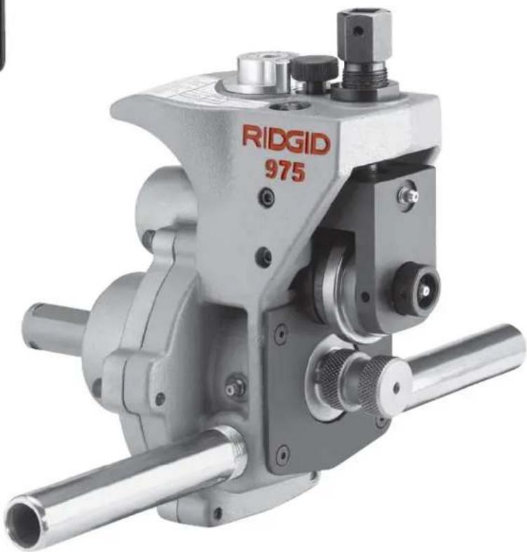
natural_image
Mechanical component labeled 'RIDGID 975' with metallic shaft and threaded ports (no readable text beyond label)WARNING!
Read this Operator's Manual carefully before using this tool. Failure to understand and follow the contents of this manual may result in electrical shock, fire and/or serious personal injury.
- Français – 23
General Safety Rules
Work Area Safety....2
Electrical Safety 2
Personal Safety ....3
Tool Use and Care....3
Service 3
Specific Safety Information
Roll Groover Safety 4
Roll Groover Safety When Used With A Power Drive/Threading Machine ....4
Roll Groover Safety When Used In Place ....4
Description, Specifications and Standard Equipment
Description....4
Specifications....5
Standard Equipment 5
Roll Groover Inspection....5
Machine and Work Area Set-Up For Power Driven Applications
Mounting The 975 Combo Groover Onto A RIDGID 300 Power Drive ....7
Mounting The 975 Combo Groover Onto A RIDGID 300 Compact Threading Machine ....7
Completing Set Up....8
Pipe Preparation 9
Pipe Set Up In Roll Groover....10
Operating The 975 Combo Roll Groover With A Power Drive/Threading Machine
Setting/Measuring The Groove Diameter 10
Forming The Roll Groove....11
Setting The Groove Diameter For Copper Tubing....12
975 Combo Roll Groover Tracking Tips....12
Machine and Work Area Set Up For In Place Applications
Pipe Preparation ....14
Mounting The Roll Groover To The Pipe 14
Operating The 975 Combo Roll Groover In Place
Setting/Measuring The Groove Diameter 15
Forming The Roll Groove....16
Maintenance Instructions
Lubrication 16
Cleaning....17
Changing Roll Sets 17
Accessories 18
Machine Storage....18
Service and Repair....18
Table I. Standard Roll Groove Specifications ....19
Table II. Pipe Maximum and Minimum Wall Thickness....19
Table III. Copper Roll Groove Specifications....20
Troubleshooting 20-21
Lifetime Warranty ....Back Cover
Combo Roll Groover
natural_image
Mechanical component labeled RIDGID 975, showing internal gears and shafts (no readable text beyond label)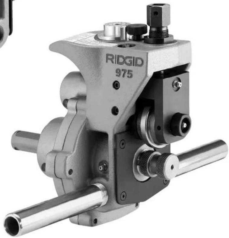
natural_image
Mechanical clamp device labeled 'RIDGID 975' with metal components and cylindrical shafts (no readable text beyond label)Safety Symbols
In this operator's manual and on the product, safety symbols and signal words are used to communicate important safety information. This section is provided to improve understanding of these signal words and symbols.

This is the safety alert symbol. It is used to alert you to potential personal injury hazards. Obey all safety messages that follow this symbol to avoid possible injury or death.

DANGER
DANGER indicates a hazardous situation which, if not avoided, will result in death or serious injury.

WARNING
WARNING indicates a hazardous situation which, if not avoided, could result in death or serious injury.

CAUTION
CAUTION indicates a hazardous situation which, if not avoided, could result in minor or moderate injury.
NOTICE
NOTICE indicates information that relates to the protection of property.

This symbol means read the operator's manual carefully before using the equipment. The operator's manual contains important information on the safe and proper operation of the equipment.

This symbol means always wear safety glasses with side shields or goggles when handling or using this equipment to reduce the risk of eye injury.

This symbol indicates the risk of fingers and hands being crushed between the groove rolls.

This symbol indicates the risk of hands, fingers, legs, clothes and other objects catching and/or wrapping on rotating shafts causing crushing or striking injuries.

This symbol indicates that a drill, impact tool, or other power tool should not be used to drive this device when used in place.

This symbol indicates the risk of machine tipping, causing striking or crushing injuries.

This symbol means always use a foot switch when using a threading machine/power drive.

This symbol means wear a hard hat when working overhead to reduce the risk of head injury.
General Safety Rules
WARNING
Read and understand all instructions. Failure to follow all instructions listed below may result in electric shock, fire, and/or serious personal injury.
SAVE THESE INSTRUCTIONS!
The term "power tool" in the warnings refers to your mains-operated (corded) power tool or battery-operated (cordless) power tool.
Work Area Safety
- Keep your work area clean and well lit. Cluttered or dark areas invite accidents.
- Do not operate power tools in explosive atmospheres, such as in the presence of flam mable liquids, gases, or dust. Power tools create sparks which may ignite the dust or fumes.
-
Keep children and by-standers away while operating a power tool. Distractions can cause you to lose control.
-
Keep floors dry and free of slippery materials such as oil. Slippery floors invite accidents.
- Guard or barricade the area when work piece extends beyond machine. A guard or barricade that provides a minimum of three (3) feet clearance around the work piece will reduce the risk of entanglement.
Electrical Safety
- Power tool plugs must match the outlet. Never modify the plug in any way. Do not use any adapter plugs with earthed (grounded) power tools. Un modified plugs and matching outlets will reduce risk of electric shock.
- Avoid body contact with earthed or grounded surfaces such as pipes, radiators, ranges and refrigerators. There is an increased risk of electrical shock if your body is earthed or grounded.
-
Do not expose power tools to rain or wet conditions. Water entering a power tool will increase the risk of electrical shock.
-
Do not abuse the cord. Never use the cord for carrying, pulling or unplugging the power tool. Keep cord away from heat, oil, sharp edges or moving parts. Damaged or entangled cords increase the risk of electric shock.
- When operating a power tool outdoors, use an extension cord suitable for outdoor use. Use of a cord suitable for outdoor use reduces the risk of electric shock.
- If operating a power tool in a damp location is unavoidable, use a ground fault circuit interrupter (GFCI) protected supply. Use of an GFCI reduces the risk of electric shock.
Personal Safety
- Stay alert, watch what you are doing and use common sense when operating a power tool. Do not use a power tool while you are tired or under the influence of drugs, alcohol, or medication. A moment of inattention while operating power tools may result in serious personal injury.
- Use personal protective equipment. Always wear eye protection. Protective equipment such as dust mask, non-skid safety shoes, hard hat, or hearing protection used for appropriate conditions will reduce personal injuries.
- Prevent unintentional starting. Ensure the switch is in the off-position before connecting to power source and/or battery pack, picking up or carrying the tool. Carrying power tools with your finger on the switch or energizing power tools that have the switch on invites accidents.
- Remove any adjusting key or wrench before turning the power tool on. A wrench or a key left attached to a rotating part of the power tool may result in personal injury.
- Do not overreach. Keep proper footing and balance at all times. This enables better control of the power tool in unexpected situations.
- Dress properly. Do not wear loose clothing or jewelry. Keep your hair, clothing, and gloves away from moving parts. Loose clothes, jewelry, or long hair can be caught in moving parts.
- If devices are provided for the connection of dust extraction and collection facilities, ensure these are connected and properly used. Use of dust collection can reduce dust-related hazards.
Tool Use and Care
- Do not force tool. Use the correct tool for your application. The correct tool will do the job better and safer at the rate for which it is designed.
- Do not use tool if the switch does not turn it ON and OFF. Any tool that cannot be controlled with the switch is dangerous and must be repaired.
- Disconnect the plug from the power source and/or the battery pack from the tool before making any adjustments, changing accessories, or storing tools. Such preventive safety measures reduce the risk of starting the tool accidentally.
- Store idle tools out of the reach of children and do not allow persons unfamiliar with the tool or these instructions to operate the tool. Tools are dangerous in the hands of untrained users.
- Maintain tools. Check for misalignment or binding of moving parts, breakage of parts and any other condition that may affect the tool's operation. If damaged, have the tool repaired before use. Many accidents are caused by poorly maintained tools.
- Use only accessories that are recommended for your tool. Properly maintained cutting tools with sharp cutting edges are less likely to bind and are easier to control.
- Keep handles dry and clean; free from oil and grease. Allows for better control of the tool.
Service
- Have your tool serviced by a qualified repair person using only identical replacement parts. This will ensure that the safety of the tool is maintained.
Specific Safety Information
WARNING
This section contains important safety information that is specific to this tool.
Read these precautions carefully before using the 975 Combo Roll Groover to reduce the risk of serious personal injury.
SAVE THESE INSTRUCTIONS!
Contact Ridge Tool Technical Service De partment at (800) 519-3456 or rttechservices@emerson.com if you have any questions.
Roll Groover Safety
- Do not wear loose clothing. Keep sleeves and jackets buttoned. Do not reach across the machine or pipe. Clothing can be caught by the pipe or other rotating parts, resulting in entanglement and serious injury.
- Keep hands away from grooving rolls. Do not groove pipe shorter than specified. Do not wear loose fitting gloves. Fingers can be crushed between groove rolls or between groove roll and pipe.
- Keep hands away from ends of pipe. Do not reach inside pipe. Burrs and sharp edges can catch and cut. Fingers can be crushed between groove rolls or between groove roll and pipe.
- Properly prepare and handle pipe. Burrs and sharp edges can catch and cut.
- Properly support the pipe. This will help to prevent the tipping of the pipe and equipment.
- Read and understand this operator's manual, the appropriate power drive or threading machine operator's manual, the fitting manufacturer's installation instructions and the in structions for any other equipment used with this tool before operating the RIDGID® 975 Combo Roll Groover. Failure to follow all instructions may result in property damage and/or serious personal injury.
- Always wear appropriate personal protective equipment while setting up and using the RIDGID 975 Combo Roll Groover. Appropriate personal protective equipment always includes eye protection and may include equipment such as tight fitting leather gloves, steel toed footwear, and a hardhat.
- Only use roll groover to groove pipe of recommended sizes and types according to these instructions. Other uses or modifying the roll groover for other applications may increase the risk of injury.
Roll Groover Safety When Used With A Power Drive/Threading Machine
- Only use the RIDGID 300 Power Drive or the 300 Compact Threading Machine with this 975 Combo Roll Groover. Use of other power sources will result in improper set up and could cause tipping or other issues.
- Do not use this roll groover with a power drive or threading machine that does not have a foot switch. Never block a foot switch so that it does not control the power drive. A foot switch provides better control by letting you shut off the power drive motor by removing your foot. If clothing should become
caught in the machine and power is maintained to the motor, the clothing will be pulled into the machine. This machine has high torque and can cause the clothing to bind around your arm or other body parts with enough force to crush or break bones or cause striking or other injuries.
- One person must control both the grooving process and the foot switch. Do not operate with more than one person. In case of entanglement, the operator must be in control of the foot switch.
- Only use power drives and threading machines with a rotational speed of 57 rpm or less. Higher speed machines increase the risk of injury.
- Be sure the roll groover is properly set up and secured to the power drive/threading machine. Be sure the machine, stand, groover and pipe are stable. This will help prevent tipping of the equipment and pipe.
Roll Groover Safety When Used In Place
- Only drive manually when used for in place applications. Do not use powered devices (such as drills or impact tools) to drive the roll groover when used in place. Use of powered devices can damage the Groove and increase the risk of injury.
- When working overhead, all personnel should wear hard hats and be clear of the area below. Prevents serious injuries if roll groover, pipe or other objects fall.
Description, Specifications and Standard Equipment
Description
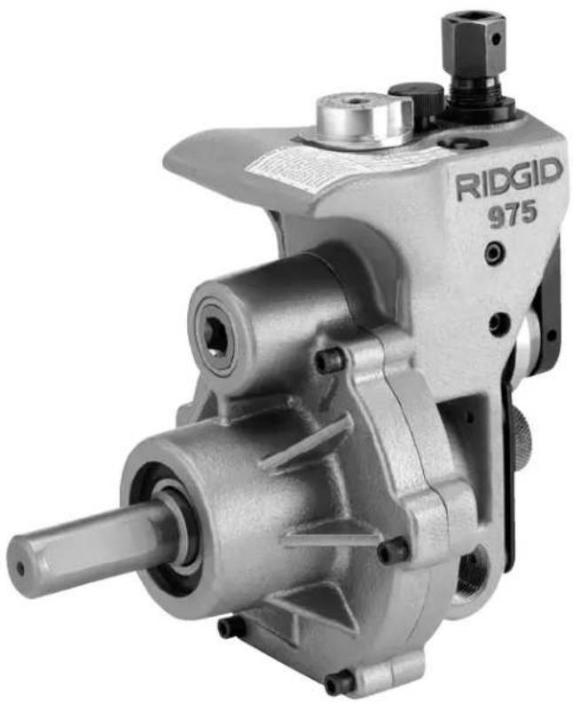
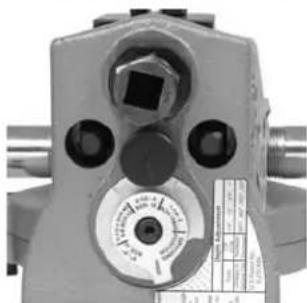
The RIDGID ^® 975 Combo Roll Groover forms rolled grooves in steel, aluminum and PVC pipe and will groove 1 ^1/4 " to 6" diameter pipe, schedule 10 and schedule 40. It is also designed to groove 1 ^1/4 " to 6" schedule 10 and 1 ^1/4 " to 2" schedule 40 stainless steel pipe. It can also be adapted for 2" - 8" Type K, L,M and DWV copper tube with a roll set change. The grooves are formed by mechanically advancing a grooving roll into the pipe which is supported by a drive roll. The only adjustment necessary is for the depth of the groove.
The unit is specifically designed to be used either in place or with the RIDGID Model 300 Power Drive (38 and 57 RPM Models). With the appropriate adapter (cat. #67662), the unit can work with the RIDGID Model 300 Compact Threading Machine. The 975 Combo Roll Groov er includes a patented groove depth gauge to aid in groove set up and patented features to improve tracking during use.
The 975 Combo Roll Groover is a portable unit intended for occasional use on the job site and should not be used for high volume work or for production work in a pipe fabrication shop.
NOTICE When properly used, the Model 975 Combo Roll Groover makes grooves 2" - 6" that are dimensionally within the specifications of AWWA C606-06. Selection of appropriate materials and joining methods is the responsibility of the system designer and/or installer. Before any installation is attempted, careful evaluation of the specific service environment, including chemical environment and service temperature, should be completed.
Specifications
Capacity ....1 ^1/4 " – 6" Schedule 10 and Schedule 40 Steel Pipe With Roll Change: 2"-8" Cop - per Tube, Type K, L ,M & DWV
(See Table II for Wall Thickness)
Groove Diameter
Adjustment ....Adjusting Screw And Groove Depth Gauge
Actuation ....Feed Screw with 12 " Ratchet Wrench
Power Drive Mounting...RIDGID 300 Power Drive (38 and 57 RPM Model Only) RIDGID 300 Compact Thread - ing Machine (with adapter)
Weight......27.6 lbs.
The 975 Combo Roll Groover is protected under U.S. and International patents, including patents 6,272,895 and 6,591,652.
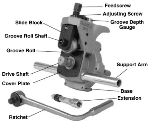
Figure 1 - 975 Combo Roll Groover
Standard Equipment
1 ^1/4 " – 6" Schedule 10 & 40 Groove and Drive Rolls Ratchet Wrench (1/2" Drive) with Button Release
Locking Extension Drive
Support Arms
Integral Index Depth Gauge
Roll Groover Inspection
WARNING

natural_image
Abstract black-and-white geometric shapes resembling stylized letters or blocks (no text or symbols)
natural_image
Abstract black-and-white graphic of a bird-like figure with a circular element, resembling a stylized bird or wing (no text or symbols)Before each use, inspect your roll groover and correct any problems to reduce the risk of serious injury from crushing injuries and other causes and prevent roll groover damage.
Do not use this roll groover with a power drive/ - threading machine that does not have a foot switch.
- If the roll groover is installed on a power drive or threading machine, make sure that the machine is unplugged and that the REV/OFF/FOR switch is in the OFF position. Inspect and maintain the power drive/ -threading machine as directed in the machine's operator's manual. Failure to properly inspect and maintain equipment can result in serious injury and property damage. Make sure that that a foot switch is present and properly operating. Do not use this roll groover without a foot switch.
- Clean any oil, grease or dirt from the roll groover, including the carry handle, and the ratchet used to activate the roll groover. This reduces the risk of injury due to the groover or ratchet slipping from your grip during use and allows easier inspection.
- Make sure that the support arms are tight in the body of the roll groover.
- Inspect the roll groover for any broken, missing, misarranged or binding parts or any other condition that may prevent the safe and normal operation. Make sure that the groove roll and drive shaft turn freely.
- Check that the warning label is present and firmly attached. See Figure 2 for the location of the warning label.
-
If the drive shaft knurls are dirty, clean with a wire brush. Dirty knurls can cause pipe slippage and tracking issues during grooving.
-
Inspect the groove roll and drive shaft for cracks, wear or other signs of damage. Damaged groove rolls and drive shafts can cause pipe slippage, poor quality grooves, or cause failure during use.
- Inspect the ratchet and extension for proper operation. Make sure that the ratchet operates smoothly and consistently in both directions. Press the release button in the center of the ratchet head and install on the feedscrew. The ratchet should firmly lock into position. The ratchet should also lock securely into the extension and the extension should securely lock into the manual drive square at the back of the roll groover. This helps to prevent the ratchet and extension from coming loose from the roll groover in use. If using a different ratchet, wrench or extension that does not lock to the roll groover, be aware that it could come loose during use.
If any problems are found, do not use the machine until the problems have been corrected.
- Lubricate the roll groover per the maintenance instructions in this manual. Wipe any excess grease from the roll groover.
- If any other equipment is being used, inspect and maintain to make sure it is functioning properly.
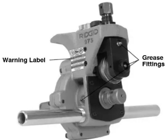
Figure 2 - 975 Combo Roll Groover Warning Label
Machine and Work Area Set-Up For Power Driven Applications
WARNING

natural_image
Four black-and-white pictograms showing different scenes: a person running with a bottle, a camera with a lens, a person holding a ring, and a printer (no text or symbols)Always wear eye protection to protect your eyes against dirt and foreign objects. Wear steel toe footwear to protect feet from tipping tools and falling pipe.
Do not use this roll groover with a power drive or threading machine that does not have a foot switch. Never block a foot switch so that it does not control the power drive. A foot switch provides better control by letting you shut off the power drive motor by removing your foot. If clothing should become caught in the machine and power is maintained to the power drive motor, the clothing will be pulled into the machine. This ma chine has high torque and can cause the clothing to bind around your arm or other body parts with enough force to crush or break bones or cause striking or other injuries.
Set up the roll groover and the work area according to these procedures to reduce the risk of injury from electric shock, fire, machine tipping, entanglement, crushing and other causes, and prevent roll groover damage.
-
Locate a work area that has the following:
-
Adequate lighting.
- No flammable liquids, vapors or dust that may ignite. If present, do not work in area until sources have been identified and corrected. Power Drives and threading machines are not explosion proof, and can cause sparks.
- Clear, level, stable and dry location for all of the equipment and the operator. Do not use the equipment while standing in water.
- Properly grounded electrical outlet. A three prong or GFCI outlet may not be properly grounded. If in doubt, have outlet inspected by a licensed electrician.
- Clear path to the electrical outlet that does not contain any potential sources of damage to the power cord.
- Clean up the work area prior to setting up any equipment. Always wipe up any oil that may be present.
- Inspect the pipe to be grooved and confirm that the 975 Combo Roll Groover is the correct tool for the job. The 975 Combo Roll Groover is designed to groove schedule 10 and 40 steel, aluminum, and PVC pipe in 114 to 6" sizes. It is also designed to groove 114 to 6"
schedule 10 and 1^1/4 to 2" schedule 40 stainless steel pipe. With a roll set change, it can be used to groove 2" - 8" Type K, L, M and DWV copper tube.
The 975 Combo Roll Groover can be used for in place applications (pipe that is in place or mounted in a vise) or with a RIDGID 300 Power Drive or 300 Compact Threading Machine for power ed applications on the job site. The 975 Combo Roll Groover is not intended for production type applications.
Roll groovers for other applications can be found by consulting the Ridge Tool catalog, on line at www.RIDGID.com, or by calling Ridge Tool Technical Services at 800-519-3456.
NOTICE Use of roll sets (groove roll and driveshaft) on both carbon and stainless steel pipe can lead to contamination of the stainless steel material. This contamination could cause corrosion and premature pipe failure. To prevent ferrous contamination of stainless steel pipe, use roll sets dedicated for stainless steel roll grooving. Alternately, a stainless steel wire brush may be used to thoroughly clean the roll set when switching between materials.
-
Make sure the power drive/threading machine has been inspected per it's manual. Confirm the presence of a foot switch and make sure that the FOR/OFF/REV switch is in the OFF position. Set up the power drive/threading machine as directed in it's manual. Make sure that the machine and stand are stable and do not wobble.
-
Fully open the chuck of the power drive/threading machine.
-
Confirm that the 975 Combo Roll Groover has been inspected and has the appropriate roll set installed.
Mounting The 975 Combo Groover Onto A RIDGID 300 Power Drive
-
If the power drive to be used is equipped with a carriage or other attachments, remove them from the power drive. Make sure the power drive support arms are fully forward and fixed in position.
-
Place the support arms of the roll groover onto the support arms of the power drive and the end of the roll groover driveshaft in the chuck of the machine. Close and tighten the power drive chuck onto the flats of the driveshaft. Make sure that the driveshaft is centered in the chuck. Use repeated and forceful counterclockwise spins of the speed chuck hammerwheel to securely grip the driveshaft (Figure 3).
natural_image
Close-up of a mechanical tool with a hand adjusting a cylindrical component (no visible text or symbols)Figure 3 – Mounting 975 Combo Roll Groover Into 300 Power Drive Chuck
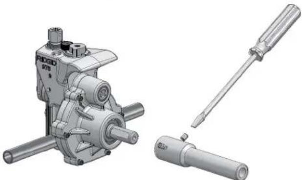
Mounting The 975 Combo Groover Onto A RIDGID 300 Compact Threading Machine
When using the 975 Combo Roll Groover with a 300 Compact Threading Machine, an adapter kit (Catalog Number 67662) must be used. This adapter kit properly positions the 975 Combo Roll Groover relative to the threading machine and stand and to allow the complete range of sizes to be grooved. Do not try to use the 975 Combo Groover with any other threading machine, as tipping or other issues may result.
- Install the drive bar adapter onto the roll groover drive shaft (See Figure 4). Align set screws with the flats on the roll groover drive shaft and firmly tighten.
natural_image
Technical illustration of a mechanical assembly with three views: a motor, a screwdriver, and a cylindrical component (no text or symbols present)Figure 4 – Installing Drive Bar Adapter
-
Move carriage on the 300 Compact Threading Machine as close to the machine chuck as possible. Move the cutter, reamer and die head in to the position away from the operator, so they are out of the way. Position reamer cone inside of die head.
-
Place the adapter bracket over the end of rails of the 300 Compact (as shown in Figure 5) and lock into place with the attached pin.
natural_image
Close-up of a hand operating a metal lathe machine tool (no visible text or symbols)Figure 5 – Installing Adapter Bracket
- Place the 975 support arms on the arms of the adapter bracket with the drive bar adapter in the chuck of the machine. Close and tighten the threading machine chuck onto the drive bar adapter. Make sure that the drive bar is centered in the chuck. Use repeated and forceful counterclockwise spins of the speed chuck hammerwheel to securely grip the drive bar.
natural_image
Mechanical assembly of a mechanical device with no visible text or symbolsFigure 6 – 975 Combo Roll Groover Properly Mounted On 300 Compact Threading Machine
Completing Set Up
- Position the foot switch so that the operator can control the power drive/threading machine, the roll groover and the pipe to be grooved. As shown in Figure 6, the position should allow the operator to:
- Stand facing the roll groover with access to (on the same side as) the FOR/OFF/REV switch.
- Control the ON/OFF action of the foot switch and quickly release the foot switch if needed.
- Have convenient access to the roll groover, pipe and ratchet wrench without reaching over the roll groover.
natural_image
Man operating a mechanical device on a tripod stand, no visible text or symbolsFigure 7 – Operator Position
- Run the power cord along the previously identified clear path. With dry hands plug the power drive into the properly grounded outlet. Keep all connections dry and off the ground. If the power cord is not long enough use an extension cord that :
• Is in good condition
- Has a three prong plug similar to that on the power drive
- Is rated for outdoor use and contains a W or W-A in the cord designation (i.e. SOW)
- Has sufficient wire size (14 AWG for 25' or less, 12 AWG for 25' – 50' long). Under sized wires can overheat, melting the insulation or causing a fire or other damage.
- Check the power drive/threading machine to make sure that it is operating correctly:
- Move the switch to the FOR (Forward) position. Press and release the foot switch. Confirm that the driveshaft rotates in a counter-clockwise direction as you face the front chuck. If the unit does not
rotate in the correct direction or the foot switch does not control the machine operation, do not use the machine until it has been repaired.
- Depress and hold the foot switch. Check the rotational speed of the unit. Inspect the moving parts for misalignment, binding, odd noises or any other unusual conditions. Release foot switch. If the rotational speed exceeds 57 rpm, do not use the unit for roll grooving. Higher speeds may increase the risk of injury. If unusual conditions are found, do not use the equipment until it has been repaired.
- Move the switch to the REV (reverse) position. Press and release the foot switch. Con firm that the driveshaft rotates in a clockwise direction as you face the front of the chuck. If the unit does not rotate in the correct direction, do not use the machine until it has been repaired.
- Move the switch to the OFF position. With dry hands unplug the machine.
Pipe Preparation
NOTICE These are generalized instructions. Always follow grooved coupling manufacturer's specific recommendations for pipe end preparation. Failure to follow the grooved coupling manufacturer's recommendations may lead to an improper connection and cause leaks.
- Cut pipe to proper length. Be aware of the minimum lengths of pipe that can be grooved for each size of pipe (See Chart A). Grooving pipe shorter than minimum length increases the risk of injury from crushed fingers and entanglement.
Make sure pipe end is cut square and free of burrs. Burrs can catch or cut gloves or fingers during grooving. Cut off method and large burrs can effect the quality of the groove made and the tracking of the Groove. Do not attempt to groove pipe that has been cut with a torch. - All internal/external weld beads, flash, or seams must be ground flush at least 2" back from the end of the pipe. Do not cut flats into gasket seat area, this could cause leaks.
- Remove all scale, dirt, rust and other contaminants at least 2" back from the end of the pipe. Contaminants can clog the drive knurls and prevent proper driving and tracking of the pipe while grooving.
Pipe Set Up In Roll Groover
-
Confirm that the power drive switch/threading machine is in the OFF position.
-
Make sure to have appropriate support available for the pipe you are going to be grooving. Chart A lists the maximum length of pipe to be grooved using a single pipe stand. Longer lengths of pipe should be supported with at least two pipe stands. Failure to properly support the pipe may allow the pipe or the pipe and machine to tip and fall. Do not groove pipe shorter than the minimum length.
Nom. Min. Max. Nom. Min. Max. Size Length Length Size Length Length
| 1 8 36 4 8 36 | |||||
| 1^1/_4 | 8 | 36 | 4^1/_2 | 8 | 32 |
| 1^1/_2 | 8 | 36 | 5 | 8 | 32 |
| 2 8 36 | 6 O.D. | 10 30 | |||
| 2^1/_2 | 8 36 6 | 10 28 | |||
| 3 | 8 | 36 | |||
| 3^1/_2 | 8 | 36 | |||
Chart A – Minimum/Maximum Pipe Length To Be Grooved With One Stand (All Dimensions In Inches)
- Place the required pipe stands in front of the roll groover. For lengths supported by a single stand, the stand should be placed slightly more than half the length of the pipe from the roll groover cover plate. For lengths of pipe requiring more than one stand, the stands should be placed 14 of the pipe length from the ends of the pipe. It may be appropriate to use more stands in some situations. Stand height should be adjusted so that the pipe can fit over the drive roll.
- Make sure that the groove roll has been retracted enough to allow the pipe to be placed over the drive shaft. If needed, turn the feedscrew counter-clockwise to raise the groove roll.
- Place the pipe end over the driveshaft and set the pipe down onto the pipe stand(s). Make sure the pipe is stable.
Figure 8 – Placing Pipe Over Driveshaft and Flush To Cover Plate
- Adjust pipe and pipe stands so that the end of the pipe is flush to the roll groover cover plate and that the inside of the pipe contacts the top of the driveshaft
(Figure 7). The centerline of the pipe and the centerline of the drive shaft should be parallel to one another. One way to do this is to level both the pipe and the power drive/threading machine.
- Slightly offset the pipe and pipe stands approximately 12 degree (about 1" over at 10 feet from the roll groo- ver) towards the operator. Proper alignment of the pipe and roll groover helps to insure proper tracking of the pipe while grooving. (See Figure 9.)
Figure 9 – Offsetting The Pipe 1/2° Towards Operator (Exaggerated)
-
Turn the feedscrew clockwise to bring the groove roll down in contact with the pipe outside diameter, then turn the feedscrew one quarter additional turn. The adjusting screw may need to be loosened (turned counter-clockwise) to allow the groove roll to contact pipe. The pipe and roll groover should be secure to each other at this point.
-
Evaluate the work area and determine if any barriers are required to keep people other than the operator
away from the equipment and pipe. Guards or barricades should be used to create a minimum of three (3) feet of clearance around the power drive and pipe. This "safety zone" prevents others from accidentally contacting the machine or pipe and causing tipping or becoming entangled in the rotating parts.
- With dry hands, plug the machine into the properly grounded outlet.
Operating The 975 Combo Roll Groover With A Power Drive/Threading Machine
WARNING

natural_image
Six black-and-white icons representing various activities: a helmet, motion capture, water spray, computer monitor, and falling object (no text or symbols)Do not wear loose clothing when operating the roll groover. Keep sleeves and jackets buttoned. Do not reach across the machine or pipe. Loose clothing can become entangled in rotating parts and cause crushing injuries.
Keep hands away from grooving rolls. Do not groove pipes shorter than specified. Do not wear loose fitting gloves. Fingers can be crushed between groove rolls or between groove roll and pipe.
Keep hands away from ends of pipe. Do not reach inside pipe. Burrs and sharp edges can catch and cut. Fingers can be crushed between groove rolls or between groove roll and pipe.
Always wear eye protection to protect your eyes against dirt and foreign objects. Wear steel toe footwear to protect feet from tipping tools and falling pipe.
Follow operating instructions to reduce the risk of injury from crushing, tipping, striking and other causes.
Setting/Measuring The Groove Diameter
NOTICE Due to differing pipe characteristics, a test groove should always be performed before the first groove of the day or when changing pipe size, schedule or material. Groove diameter setting gauges are approximate only and the groove diameter must be measured to confirm proper size.
-
Confirm that the equipment and pipe is properly set up. Improper pipe preparation can effect the accurate set up of the groove depth gauge. The groove roll should be touching the pipe.
-
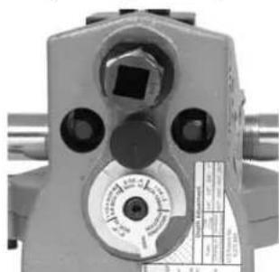
Adjust the groove depth gauge so that the correct step of the gauge is under the head of the adjusting screw (Figure 10A). The groove depth gauge is
designed for use with pipe. See "Setting The Groove Diameter For Copper Tube" for use with copper tube.
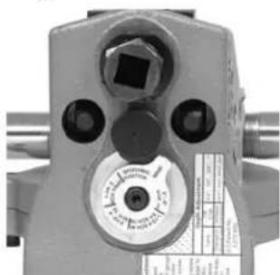
- Turn the adjusting screw clockwise until the head touches the step of the depth gauge. Turn the groove depth gauge to the grooving position (Figure 10B). If the gauge is not in the grooving position it will prevent grooving and may be damaged.
natural_image
Close-up of a mechanical surveying instrument with no visible text or symbols on the device itself.Figure 10A – Place Correct Step of Gauge Under Adjusting Screw Head
natural_image
Close-up of a surveying instrument with no visible text or symbols on the bodyFigure 10B – Gauge In Grooving Position
- Prepare a test groove (follow the steps for "Forming the Roll Groove).
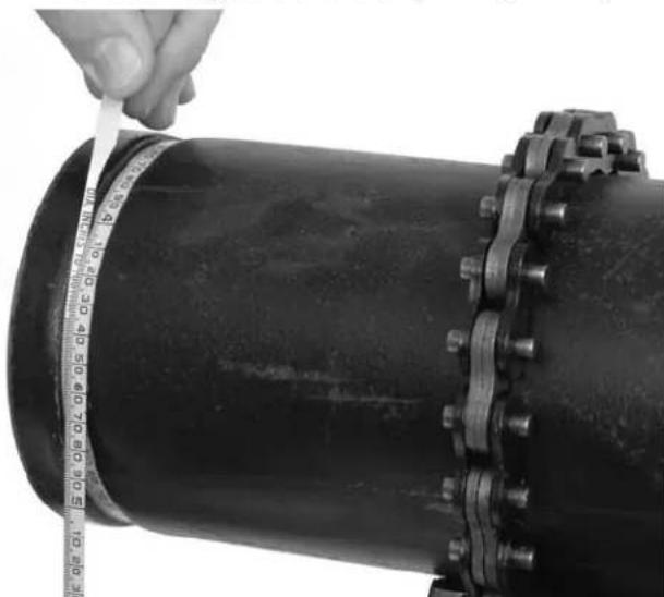
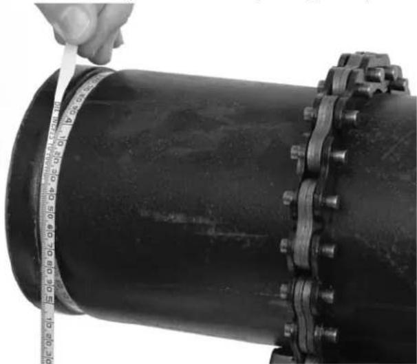
- Measure the groove diameter. The best method for measuring groove diameter is the use of a diameter tape (see Accessories Section). Snugly wrap the diameter tape around the pipe in the groove. Make sure that the tape sits flat in the bottom of the groove, and read the groove diameter. (See Figure 11.)
natural_image
Close-up of a hand measuring a black pipe with a tape measure, showing measurement markings (no text or symbols on the pipe itself)Figure 11 – Checking Groove Diameter With A Diameter Tape
- Compare the measured groove diameter to the required groove diameter as shown in Table I or III or as specified by the groove fitting manufacturer. If the measured groove is outside of the required groove
diameter, the adjusting screw must be repositioned to give the correct groove diameter.
• To increase groove diameter, turn the adjusting screw clockwise.
- To decrease groove diameter, turn the adjusting screw counter-clockwise.
• Each 14 turn of the adjusting screw changes the groove diameter approximately 0.02".
- Repeat steps 4-6 until the groove diameter is within specifications. If the groove is too large, the groover can be adjusted and the groove made smaller. If the groove is too small, another groove will need to be made. Proper groove diameter is important to insure connection performance. Out of specification grooves could cause joint failure.
Forming The Roll Groove
- Confirm that the equipment and pipe are properly set up.
natural_image
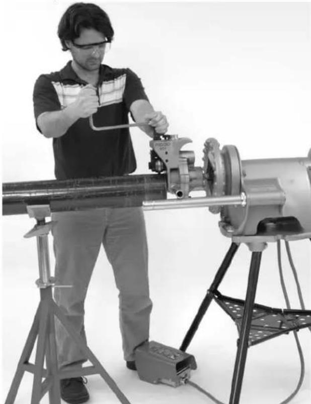
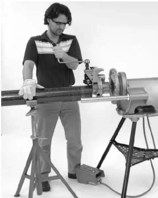
Man operating a large cylindrical mechanical device with a clamp, no visible text or symbolsFigure 12 – Roll Groover Operating Position
-
Assume a proper operating position. Position the power drive foot switch so that the operator can control the power drive, the roll groover and the pipe to be grooved. As shown in Figure 12, the position should allow the operator to:
-
Stand facing the roll groover with access to (on the same side as) the FOR/OFF/REV switch.
- Control the ON/OFF action of the foot switch and quickly release the foot switch if needed.
- Have convenient access to the groover and ratchet wrench without reaching over the roll groover.
- Place right hand on pipe being grooved if needed.
-
Have good footing and proper balance.
-
Move the FOR/OFF/REV switch to the REV (reverse position). Do not run the 975 Combo Roll Groover in the FOR (forward). Because of the design of the 975 Combo Roll Groover, this will cause the pipe to "spiral" out of the roll groove rolls and may allow the pipe to fall.
-
Place one hand on the head of the ratchet/top of the feedscrew and the other hand on the end of the ratchet.
-
Press the foot switch to start the power drive. Watch the pipe rotate and be sure that the face of the pipe stays in contact with the cover plate of the roll groover. If the pipe starts to move away from the roll groover cover plate, release the foot switch to prevent the pipe from spiraling off and falling. If needed, re-set up the pipe (see Pipe Set Up Section). If the pipe end is deformed, it will need to be cut off and a new groove prepared.
-
As the pipe completes a full rotation, tighten the feed-screw another 14 turn. Continue to monitor the pipe end to make sure that it is in contact with the cover plate. Do not tighten the feedscrew more than 14 turn per pipe rotation. Aggressive tightening of the feedscrew can cause excessive groove flare or cause the pipe to spiral off the drive shaft.
-
Continue tightening the feedscrew 14 turn per pipe revolution until the head of the adjusting screw stops against the top of the roll groover. Do not continue tightening the feedscrew after the adjusting screw reaches the top of the roll groover, this can damage the adjusting screw. Allow the pipe to rotate at least two more full rotations in this position to insure uniform groove depth.
-
Release the foot switch and move the FOR/OFF/REV switch to the OFF position.
-
Turn the feedscrew counter-clockwise and raise the groove roll so that the pipe can be removed from the machine.
-
Inspect the groove.
- Make sure that the groove is fully formed.
- Check the groove diameter and make sure it is within specification.
- Check any other items required by the fitting manufacturer.
If any problems are found, the groove cannot be used.
Setting The Groove Diameter For Copper Tubing
When using the 975 Combo Roll Groover for copper tube, the groove depth gauge on the groover cannot be used. It will give incorrect groove diameters.
- Turn the feedscrew clockwise to bring the groove roll down in contact with the pipe outside diameter, then turn the feedscrew one quarter additional turn. The adjusting screw may need to be loosened (turned counter-clockwise) to allow the groove roll to contact pipe. The pipe and roll groover should be secure to each other at this point.
- Make sure the groove depth gauge is in the grooving position. (Figure 10B)
- Turn the adjusting screw until it is flush with the top plate of the groover.
- Find the diameter and type of pipe to be grooved on Table B and back the adjusting screw off the top plate the corresponding number of turns. For example, for 4" Sch. L copper, back the adjustment screw 1 ^1/4 turns.
Depth Adjustment for Roll Grooving Copper Tubing (Adjusting Screw Turns)
Dia. K L|M DWV
| 2-2.5" | ^7/_8 | ^7/_8 | ^5/_8 | ^5/_8 |
| 3" 1 | ^1/_16 | 1^1/_16 | 1^1/_16 | 1^1/_16 |
| 4" 1 | ^1/_4 | 1^1/_4 | 1^1/_4 | 1^1/_8 |
| 5" 1 | ^1/_2 | 1^1/_2 | 1^1/_2 | 1^1/_2 |
| 6" 1 | ^13/_16 | 1^3/_4 | 1^3/_4 | 1^3/_4 |
| 8" 2 | ^1/_2 | 2^3/_8 | 2^1/_8 | 2^1/_8 |
Chart B – Depth Adjustment for Roll Grooving Copper Tubing
- Go to step 4 of "Setting/Measuring The Groove Diameter".
975 Combo Roll Groover Tracking Tips
The main issue users encounter when roll grooving is the pipe "spiraling" or "walking off" the driveshaft or not "tracking" properly. For good tracking, it is important that all of the instructions are followed. If, even after following all instructions, the pipe will not properly track, there are several other options to improve tracking.
- Slightly increase the offset of the pipe towards the operator (increase from 12 degree to 1 degree) (See Figure 9).
- The operator may need to apply slight force on the pipe while grooving to maintain tracking. This is usually only needed on shorter sections of pipe. To do this, the operator should wear a leather glove in good condition and cup their hand around the middle of the pipe as shown in Figure 13. This may require that the stand to which the power drive/threading machine is mounted be fixed to the floor to prevent movement during grooving. To prevent crushing injuries, keep hand away from the groove roll and the ends of the pipe, and do not groove pipe shorter that recommended.
natural_image
Man operating a large cylindrical mechanical device with a clamp, surrounded by a stand and equipment (no visible text or symbols)Figure 13 – Applying Force To Pipe While Grooving To Maintain Tracking
- Additionally, see the Troubleshooting Section for a complete list of reasons for and solutions to tracking issues.
Machine and Work Area Set-Up For In Place Applications
WARNING


Always wear eye protection to protect your eyes against dirt and foreign objects. Wear steel toe footwear to protect feet from tipping and falling pipe and tools. When working in place, wear a hard hat.
Set up roll groover and work area according to these procedures to reduce the risk of injury from machine tipping, crushing and other causes, and prevent roll groover damage.
-
Locate a work area that has the following:
-
Adequate lighting.
- No flammable liquids, vapors or dust that may ignite. If present, do not work in area until sources have been identified and corrected.
-
Clear, level, stable and dry location with adequate space for all of the equipment and the operator.
-
Clean up the work area prior to setting up any equipment. Always wipe up any oil that may be present.
-
Inspect the pipe to be grooved and confirm that the 975 Combo Roll Groover is the correct tool for the job. The 975 Combo Roll Groover is designed to groove schedule 10 and 40 steel, aluminum, and PVC pipe in 1^1/4 to 6" sizes. It is also designed to groove 1^1/4 to 6" schedule 10 and 1^1/4 to 2" schedule 40 stainless steel pipe. With a roll set change, it can be used to groove 2" - 8" Type K, L, M and DWV copper tube.
The 975 Combo Roll Groover can be used for in place applications (pipe that is in place or mounted in a vise) or with a RIDGID 300 Power Drive or 300 Compact Threading Machine for power ed applications on the job site. The 975 Combo Roll Groover is not intended for production type applications.
-
When grooving in place, make sure that there will be enough space for the 975 Combo Roll Groover to fit and be operated. The roll groover will orbit around the solidly mounted pipe and requires:
-
A minimum of 6^1/2 clear space around the pipe to the be grooved
- A minimum of 2 12 " pipe extending past an obstruction such as a wall
- A minimum opening of 9^1/2 to fit the roll groover onto the pipe
Roll groovers for other applications can be found by consulting the Ridge Tool catalog, on line at www.RIDGID.com, or by calling Ridge Tool Technical Services at 800-519-3456.
NOTICE Use of roll sets (groove roll and driveshaft) on both carbon and stainless steel pipe can lead to contamination of the stainless steel material. This contamination could cause corrosion and premature pipe failure. To prevent ferrous contamination of stainless steel pipe, use roll sets dedicated for stainless steel roll grooving. Alternately, a stainless steel wire brush may be used to thoroughly clean the roll set when switching between materials.
Pipe Preparation
NOTICE These are generalized instructions. Always follow grooved coupling manufacturer's specific recommendations for pipe end preparation. Failure to follow the grooved coupling manufacturer's recommendations may lead to an improper connection and cause leaks.
- If grooving in place on an existing piping, make sure that the system has been depressurized and emptied of contents. Know what the contents are and any hazards associated with them.
- Cut pipe to proper length.
Make sure pipe end is cut square and free of burrs. Burrs can catch or cut gloves or fingers during grooving. Cut off method and large burrs can effect the quality of the groove made and the tracking of the Groove. Do not attempt to groove pipe that has been cut with a torch.
- All internal/external weld beads, flash, or seams must be ground flush at least 2" back from the end of the pipe. Do not cut flats into gasket seat area, this could cause leaks.
- Remove all scale, dirt, rust and other contaminants at least 2" back from the end of the pipe. Contaminants can clog the drive knurls and prevent proper driving and tracking of the pipe while grooving.
- Make sure that the pipe to be grooved is solidly mounted. The pipe must be able to withstand the weight of the roll groover (28 pounds), and the force and torque required for grooving without moving. For pipe that is in place, it may make sense to re move the pipe and groove at a pipe vise. In other cases, it may be necessary to add other temporary or permanent pipe supports. When using a pipe vise, make sure that it is secure and will not tip during use. For longer lengths of pipe, use appropriate pipe stands to support the extra length.
Mounting The Roll Groover To The Pipe
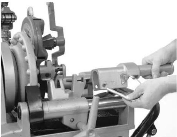
- Confirm that the 975 Combo Roll Groover has been inspected and has the appropriate roll set installed. Make sure that the support arms are tight in the body of the roll groover or remove them completely for better access in tight spaces. Next, install the ratchet into the feedscrew and install the extension into the manual drive square at the back of the roll groover. Make sure both the ratchet and extension are securely installed.
- Make sure that there is enough space between the groove roll and drive shaft for the pipe wall. If needed, turn the feedscrew counter-clockwise to retract the groove roll.
- Securely grasp the roll groover. Do not lift with the ratchet. Place the driveshaft into the pipe and make sure that the cover plate is tight to the end of the pipe (Figure 14). Tighten the feedscrew to bring the groove roll into contact with the outside of the pipe. Once the feedscrew is hand tight, use the ratchet to tighten the feedscrew an additional 14 turn. Confirm that the roll groover is securely attached to the pipe and the cover plate is flush to the end of the pipe. If not, repeat procedure. Always make sure groover is secure when used in place to prevent it from falling.
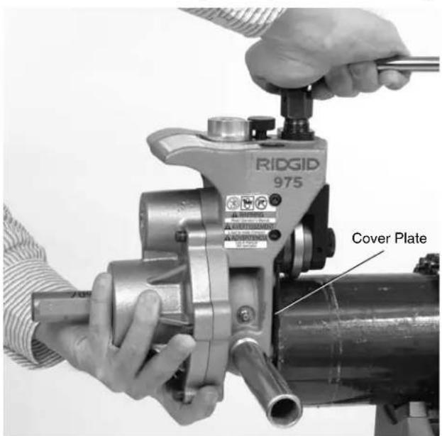
Figure 14 – Holding the Roll Groover In Place While Tightening the Feedscrew
Operating The 975 Combo Roll Groover In Place
WARNING


Only drive manually when used for in place applications. Do not use powered devices (such as drills or impact tools) to drive the roll groover when used in place. Use of powered devices can damage the groover and increase the risk of injury.
Do not wear loose clothing when operating the roll groover. Keep sleeves and jackets buttoned. Do not reach across the machine or pipe. Loose clothing can become entangled in rotating parts and cause crushing injuries.
Keep hands away from grooving rolls. Do not groove pipes shorter than specified. Do not wear loose fitting gloves. Fingers can be crushed between groove rolls or between groove roll and pipe.
Keep hands away from ends of pipe. Do not reach inside pipe. Burrs and sharp edges can catch and cut. Fingers can be crushed between groove rolls or between groove roll and pipe.
Always wear eye protection to protect your eyes against dirt and foreign objects. Wear steel toe foot - wear to protect feet from tipping tools and falling pipe. When working in place, wear a hard hat.
Follow operating instructions to reduce the risk of injury from crushing, tipping, striking and other causes.
Setting/Measuring The Groove Diameter
NOTICE Due to differing pipe characteristics, a test groove should always be performed before the first groove of the day or when changing pipe size, schedule or material. Groove diameter setting gauges are approximate only and the groove diameter must be measured to confirm proper size.
-
Confirm that the equipment and pipe are properly set up. Improper pipe preparation can effect the accurate set up of the groove depth gauge. The groove roll should be touching the pipe.
-
Adjust the groove depth gauge so that the correct step of the gauge is under the head of the adjusting screw (Figure 15A). The groove depth gauge is designed for use with pipe. See "Setting The Groove Diameter For Copper Tube" for use with copper tube.
-
Turn the adjusting screw clockwise until the head
touches the step of the depth gauge. Turn the groove depth gauge to the grooving position (Figure 15B). If gauge is not in the grooving position it will prevent grooving and may be damaged.
natural_image
Close-up of a surveying instrument with no visible text or symbols on the device itselfFigure 15A – Place Correct Step of Gauge Under Adjusting Screw Head
natural_image
Close-up of a surveying instrument with no visible text or symbols on the bodyFigure 15B – Gauge In Grooving Position
- Prepare a test groove (follow the steps for "Forming the Roll Groove).
- Measure the groove diameter. The best method for measuring groove diameter is the use of a diameter tape (See Accessories Section). Snugly wrap the diameter tape around the pipe in the groove. Make sure that the tape sits flat in the bottom of the groove, and read the groove diameter (See Figure 16).
natural_image
Close-up of a hand measuring a black pipe with a tape measure, no visible text or symbolsFigure 16 – Measuring The Groove Diameter With A Diameter Tape
- Compare the measured groove diameter to the required groove diameter as shown in Table I or III or as specified by the groove fitting manufacturer. If the measured groove is outside of the required groove diameter, the adjusting screw must be repositioned to give the correct groove diameter.
- To increase groove diameter, turn the adjusting screw clockwise.
- To decrease groove diameter, turn the adjusting screw counter-clockwise.
-
Each 14 turn of the adjusting screw changes the groove diameter approximately 0.02".
-
Repeat steps 4-6 until the groove diameter is within specifications. If the first groove is too large, the Groove can be adjusted and the groove made smaller. If the groove is too small, another groove will need to be made. Proper groove diameter is important to insure connection performance. Out of specification grooves could cause joint failure.
Forming The Roll Groove
- Confirm that the equipment and pipe are properly set up.
- Assume a proper operating position. Make sure that your footing is good and you are well balanced.
- Make sure that the feedscrew has been tightened 14 turn.
- Remove the ratchet from the feedscrew and securely install in the extension. (In close quarters applications, the extension does not need to be used.)
- Turn the ratchet clockwise as viewed from the back of the roll groover (this will match the arrows cast into the back of the roll groover, see Figure 17). Watch the groover rotate and be sure that the cover plate of the roll groover stays in contact with the end of the pipe. If the roll groover starts to move away from the pipe end, stop rotating the ratchet to prevent the roll groover from spiraling off the pipe end and falling. The roll groover support arms can be pushed on to help bring the cover plate back in contact with the pipe end. If needed, re-mount the roll groover to the pipe. (see "Mounting Roll Groover to Pipe" section). If the pipe end is deformed, it will need to be cut off and a new groove prepared.
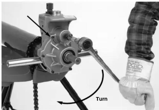
Figure 17 – Turning the Ratchet in the Direction of the Arrows
-
Continue rotating the ratchet until the roll groover completes at least a full rotation around the pipe. Remove the ratchet from the extension and attach to the feedscrew. Tighten the feedscrew another 1/4 turn. Remove the ratchet from the feedscrew and securely attach to the extension. Do not tighten the feedscrew more than 1/4 turn per pipe rotation. Aggressive tightening of the feedscrew can cause excessive groove flare and can cause the roll groover to walk off the pipe. Continue rotating the ratchet to drive the roll groover around the pipe while monitoring the position of the cover plate to the end of the pipe.
-
Continue tightening the feedscrew 14 turn per groove revolution around pipe until the head of the adjusting screw stops against the top of the roll groover. Do not continue tightening the feedscrew after the adjusting screw reaches the top of the roll groover, this can damage the adjusting screw. Rotate the roll groover at least two more full rotations around the pipe after the adjusting screw reaches the top of the roll groover to insure uniform groove depth.
-
Move the ratchet to the feedscrew. Securely grasp the roll groover. Turn the feedscrew counter-clockwise and retract the groove roll so that the roll groover can be removed from the pipe. Do not drop the roll groover.
-
Inspect the groove.
-
Make sure that the groove is fully formed.
- Check the groove diameter and make sure it is within specification.
- Check any other items required by the fitting manufacturer.
If any problems are found, the groove cannot be used.
Maintenance Instructions
WARNING
Make sure the power drive switch is in the OFF position and the unplugged before performing any maintenance or making any adjustments.
Lubrication
Lubricate the 975 Combo Roll Groover with a good general purpose grease once a month.
- Grease fittings are located on the side of the operator's side of the base, the front of the slide block, and the end of the groove roll shaft (See Figure 2). Add grease until a small amount is pushed out.
- Apply a light coat of grease to the feedscrew.
- The gear box of the 975 Combo Roll Groover is greased for life and does not require the addition of any grease unless the gear box is opened.
See Inspection Section for other information on maintenance.
Cleaning
Clean the driveshaft knurls with a wire brush on a daily basis or more often if needed.
Changing Roll Sets
NOTICE When changing roll set parts, always make sure drive and groove roll markings match. Mismatched parts can make improper grooves and cause leaks.
Remove the roll groover from the power drive or threading machine and place on a stable work bench.
Required Tools:
- ^3/_8 " Hex Wrench
- ^3/_32 " Hex Wrench
• .070" External Retaining Ring Pliers
Removing and Installing Drive Roll
- Remove 6 screws that hold rear cover to the housing.
- Remove the rear cover (See Figure 18).
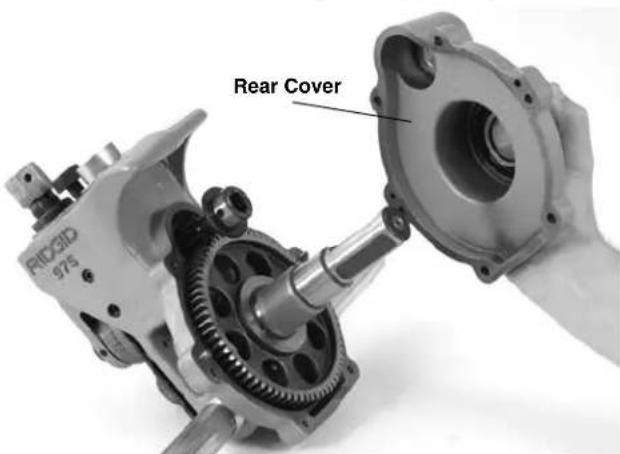
Figure 18 – Removing Rear Cover
- Remove pinion.
- Remove the driveshaft assembly out of the back of the 975 Roll Groover.
- Remove retaining ring from driveshaft and slide gear off. (See Figure 19.)
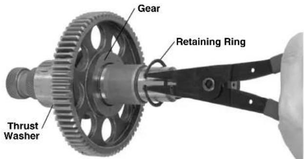
Figure 19 – Removing Retaining Ring
- Remove key and then thrust washer.
- Slide thrust washer onto new driveshaft.
- Insert key and install gear.
- Install retaining ring into driveshaft groove.
- Place driveshaft assembly into main housing.
- Grease from the gearbox may have been lost during the driveshaft change. Make sure the bearings and gear teeth are coated sufficiently with a good general purpose grease.
- Insert pinion and reinstall rear cover. Tighten screws to 12-16 ft*lbs of torque.
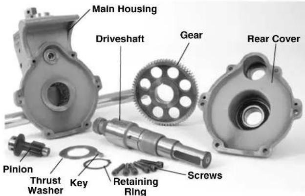
Figure 20 - 975 Combo Roll Groover Parts Diagram
Removing and Installing Groove Roll
- Remove the setscrew that holds the groove roll shaft in place.
- Pull the groove roll shaft out of the slide block and remove the groove roll and thrust washer.
- Insert the thrust washer and new groove roll into the slide block. Ensure that the internal retaining ring in the groove roll is closest to the main housing, and that the groove roll is between the thrust washer and main housing.
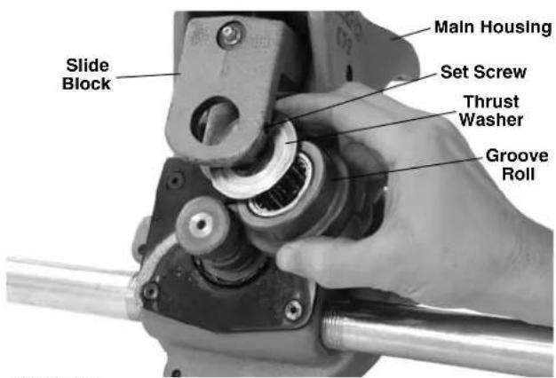
Figure 21
- Replace the groove roll shaft and the set screw.
- Visually inspect the alignment between the groove roll and the drive roll. If they are not aligned, check orientation of groove roll and thrust washer.
- Grease as directed in Lubrication Section of manual.
Accessories
WARNING
The following RIDGID products have been designed to function with the 975 Combo Roll Groover. Other accessories suitable for use with other tools may be hazardous when used on the 975 Combo Roll Groover. To reduce the risk of serious injury, only use accessories specifically designed and recommended for use with the 975 Combo Roll Groover, such as those listed in the chart.
| Cat. Number | Description |
| 41855 300 | Power Drive, 115V 25-60Hz 38RPM |
| 75075 300 | Power Drive, 115V 23-60Hz 57RPM |
| 42360 1206 | Stand for 300 Power Drive |
| 66947 300 | Compact, 115V 50/60Hz 38RPM |
| 73447 300 | Compact, 115V 50/60Hz 52RPM |
| 67662 Adapter Bracket for 300 Compact | |
| 67657 250 | Folding Wheel Stand for 300 Compact |
| 72037 460 | Portable TRISTAND Chain Vise |
| 56662 VJ-99 VHead High Pipe Stand | |
| 76822 Inch Diameter Tape | |
| 76827 Metric Diameter Tape | |
| 30708 Extension, ^1/_2 " Drive, Locking | |
| 30703 Ratchet, ^1/_2 " Drive With 90° bend | |
| 32833 Groove and Drive Rolls for 2" - 8" Copper Tube Type K, L, M and DWV | |
Machine Storage
WARNING Store the tool in a locked area that is out of reach of children and people unfamiliar with roll groover equipment. This tool can cause serious injury in the hands of untrained users.
Service and Repair
WARNING
Improper service or repair can make machine unsafe to operate.
The "Maintenance Instructions" will take care of most of the service needs of this machine. Any problems not addressed by this section should only be handled by an authorized RIDGID service technician.
Tool should be taken to a RIDGID Independent Authorized Service Center or returned to the factory.
When servicing this machine, only identical replacement parts should be used. Use of other parts may create a risk of serious injury.
If you have any questions regarding the service or repair of this machine, call or write to:
Ridge Tool Company
Technical Service Department
400 Clark Street
Elyria, Ohio 44035-6001
Tel: (800) 519-3456
E-mail: rtctechservices@emerson.com
For name and address of your nearest Independent Authorized Service Center, contact the Ridge Tool Company at (800) 519-3456 or www.RIDGID.com
Table I. Standard Roll Groove Specifications For Pipe of IPS Dimensions
NOTE! All Dimensions are in Inches.
| NOM. PIPE MIN. GASKET GROOVE GROOVE GROOVE PIPE DIAMETER WALL SEAT WIDTH | T NOM. DIAMETER THK. | A GROOVE +.015/-.030 | B O.D. | C TOL. | DEPTH (Ref.) (2) | ||
| SIZE | O.D. | TOL. | |||||
| 1^1/_4 | 1.660 | +.016 -.016 | .065 | .625 | .344 | 1.535 | +.000 -.015 |
| 1^1/_2 | 1.900 | +.016 -.016 | .065 | .625 | .344 | 1.775 | +.000 -.015 |
| 2^(1) | 2.375 | +.024 -.016 | .065 | .625 | .344 | 2.250 | +.000 -.015 |
| 2^1/_2^(1) | 2.875 | +.029 -.016 | .083 | .625 | .344 | 2.720 | +.000 -.015 |
| 3^(1) | 3.50 | +.030 -.018 | .083 | .625 | .344 | 3.344 | +.000 -.015 |
| 3^1/_2^(1) | 4.00 | +030 -.018 | .083 | .625 | .344 | 3.834 | +.000 -.015 |
| 4^(1) | 4.50 | +.035 -.020 | .083 | .625 | .344 | 4.334 | +.000 -.015 |
| 5^(1) | 5.563 | +.056 -.022 | .109 | .625 | .344 | 5.395 | +.000 -.015 |
| 6^(1) | 6.625 | +.050 -.024 | .109 | .625 | .344 | 6.455 | +.000 -.015 |
(1) As per AWWA C606-06
(2) Nominal Groove Depth is provided as a reference dimension only. Do not use groove depth to determine acceptability of a groove.
Table II. Pipe Maximum and Minimum Wall Thickness
NOTE! All Dimensions are in Inches.
| Pipe Size | CARBON STEEL OR ALUMINUM PIPE OR TUBE PIPE OR TUBE | STAINLESS STEEL | PVC PIPE | |||
| Wall Thickness | Wall Thickness | Wall Thickness | ||||
| Min. | Max. | Min. | Max. | Min. | Max. | |
| 1^1/_4" | .065 | .140 | .065 | .140 | .140 | .140 |
| 1^1/_2" | .065 | .145 | .065 | .145 | .145 | .200 |
| 2" | .065 | .154 | .065 | .154 | .154 | .218 |
| 2^1/_2" | .083 | .203 | .083 | .188 | .203 | .276 |
| 3" | .083 | .216 | .083 | .188 | .216 | .300 |
| 3^1/_2" | .083 | .226 | .083 | .188 | .226 | .226 |
| 4" | .083 | .237 | .083 | .188 | .237 | .237 |
| 5" | .109 | .258 | .109 | .188 | .258 | .258 |
| 6" | .109 | .280 | .109 | .188 | .280 | .280 |
Table III. Copper Roll Groove Specifications
| 1 | 2 | 3 | 4 | 5 | 6 | 7 | 8 | |
| Nom. Tubing Outside Gasket Groove Groove Size Inches | Diameter O.D. | A | B | Max. | C | D | T | |
| Seat A ±0.03 | Width +.03 -.000 | Dia. +.00 -.02 | Depth Ref.1 | Allow. Wall Thick. | Allow. Flare Dia. | |||
| Basic | Tolerance | |||||||
| 2" | 2.125 | ±0.002 | 0.610 | 0.300 | 2.029 | 0.048 | DWV | 2.220 |
| 21⁄2" | 2.625 | ±0.002 | 0.610 | 0.300 | 2.525 | 0.050 | 0.065 | 2.720 |
| 3" | 3.125 | ±0.002 | 0.610 | 0.300 | 3.025 | 0.050 | DWV | 3.220 |
| 4" | 4.125 | ±0.002 | 0.610 | 0.300 | 4.019 | 0.053 | DWV | 4.220 |
| 5" | 5.125 | ±0.002 | 0.610 | 0.300 | 5.019 | 0.053 | DWV | 5.220 |
| 6" | 6.125 | ±0.002 | 0.610 | 0.300 | 5.999 | 0.063 | DWV | 6.220 |
| 8" | 8.125 | +0.002/-0.004 | 0.610 | 0.300 | 7.959 | 0.083 | DWV | 8.220 |
- Nominal Groove Depth is provided as a reference dimension. Do not use groove depth to determine groove acceptability.
Troubleshooting
| SYMPTOM POSSIBLE REASONS SOLUTION | ||
| Roll groove too narrow or too wide. | Grooving roll and/or driving shaft worn. | Replace grooving roll and/or drive shaft. |
| Rolled groove not perpendicular to pipe axis. | Pipe length not straight. | Use straight pipe. |
| Pipe end not square with pipe axis. | Cut pipe end square. | |
| Pipe will not track while grooving/Groover will not track on pipe while grooving. | Pipe and drive shaft not parallel. | Adjust stand to make pipe parallel. |
| Pipe axis not offset 1/2 degree from driving roll axis. | Offset pipe 1/2 degree. | |
| Driving roll knurl plugged or worn flat. | Clean or replace drive roll. | |
| Feedscrew not tight. | Tighten feedscrew with ratchet for every revolution as per directions. | |
| Turning ratchet wrong direction. | Turn ratchet in proper direction. | |
| Inside of pipe has too much scale. | Clean inside of pipe. | |
| Excessive weld seam. | Grind weld seam flush 2" from end of pipe. | |
| Not applying pressure to pipe. | Apply pressure to pipe. (See Figure 10.) | |
| Pipe end not square/deburr. | Properly prep end of pipe. | |
| Feedscrew too tight. | Only advance feedscrew in 1/4 turn increments. | |
| Pipe flared at grooved end. | Pipe and drive shaft not parallel. | Adjust stand to make pipe parallel. |
| Feedscrew too tight. | Only advance feedscrew 1/4 turn. | |
| Pipe drifts back and forth on driving roll axis while grooving. | Pipe length not straight. | Use straight pipe. |
| Pipe end not square with pipe axis. | Cut pipe end square. | |
| Pipe rocks from side to side on driving roll while grooving. | Pipe stand is too close to end of pipe. | Move pipe stand in to match set-up Instructions. |
| Pipe end flattened or damaged. | Cut off damaged pipe end. | |
| Hard spots in pipe material or weld seams harder than pipe. | Use different pipe. | |
| Grooving roll feed rate too slow. | Feed grooving roll into pipe faster. | |
| Power drive speed exceeds 57 RPM. | Reduce speed to 57 RPM. | |
| Pipe supports stand not in correct location. | Position pipe stand rollers correctly. | |
| Groover will not roll groove in pipe. | Maximum pipe wall thickness exceeded. | Check pipe capacity chart. |
| Pipe material too hard. | Replace pipe. | |
| Adjustment screw not set. | Set depth. | |
| Power drive does not supply required minimum torque. | Use RIDGID No. 300, 38-RPM Power Drive. | |
| Groover will not roll groove to required diameter. | Maximum pipe diameter tolerance exceeded. | Use correct diameter pipe. |
| Depth adjustment screw not set correctly. | Adjust depth setting. | |
| Pipe too hard. | Use different pipe. | |
| Pipe slips on driving roll. | Grooving roll feed rate too slow. | Feed grooving roll into pipe faster. |
| Driving roll knurls plugged with metal or worn flat. | Clean or replace driving roll. | |
| Groover will not rotate pipe while grooving. | Power drive does not supply minimum required torque. | Use RIDGID No. 300, 38 RPM Power Drive. |
| Chuck not closed on drive shaft flats. | Close chuck. | |
| Pipe rises or tends to tip Groover over backwards. | Pipe support stand not properly set up. | Properly set up stands. |
natural_image
Mechanical component labeled RIDGID 975, showing internal gears and shafts (no readable text beyond label)
natural_image
Mechanical assembly component labeled 'RIDGID 975' with metallic shafts and adjustment knobs (no readable text beyond label)
AVERTISSEMENT
CONSERVEZ CES INSTRUCTIONS!
natural_image
Abstract black-and-white geometric shapes resembling stylized letters or blocks (no text or symbols)
natural_image
Abstract black-and-white graphic of a bird-like figure with a circular element, resembling a stylized bird or wing (no text or symbols)natural_image
Close-up of a mechanical tool with a hand adjusting a cylindrical component (no visible text or symbols)natural_image
Technical illustration of a mechanical assembly with three views: a motor, a screwdriver, and a cylindrical component (no text or symbols present)natural_image
Close-up of a hand operating a mechanical tool on a metal workpiece (no visible text or symbols)natural_image
Close-up of a mechanical assembly with no visible text or symbolsnatural_image
Man operating a mechanical device on a tripod stand, no visible text or symbolsFigure 7 – Position de travail
natural_image
Close-up of a mechanical surveying instrument with no visible text or symbols on the main bodynatural_image
Close-up of a surveying instrument with no visible text or symbols on the dial (pure technical drawing)Figure 10B – Jauge en position de rainurage
natural_image
Close-up of a hand measuring a black pipe with a ruler, showing measurement markings (no text or symbols on the pipe itself)natural_image
Man in safety gear operating a large industrial machine with a clamp, no visible text or symbolsFigure 12 – Positon de travail
natural_image
Man in workwear inspecting a large cylindrical mechanical device with a clamp, no visible text or symbolsnatural_image
Close-up of a surveying instrument with dial and measurement scale (no visible text or symbols)natural_image
Close-up of a surveying instrument with no visible text or symbols on the bodyFigure 15B – Jauge en position de rainurage
Technical Service Department
400 Clark Street
Elyria, Ohio 44035-6001
Tél. (800) 519-3456
E-mail: rtctechservices@emerson.com
natural_image
Mechanical component labeled RIDGID 975, showing internal gears and shafts (no readable text beyond model number)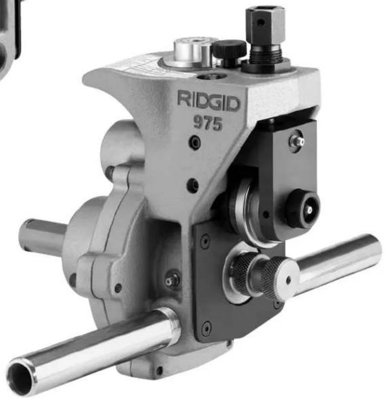
natural_image
Mechanical component labeled 'RIDGID 975' with metallic shafts and adjustment knobs (no readable text beyond label)
ADVERTENCIA
natural_image
Abstract black geometric shapes on white background (no text or symbols)
natural_image
Abstract black-and-white graphic of a bird with a human figure inside, no text or symbols present.natural_image
Close-up of a mechanical tool with a hand adjusting a circular component, no visible text or symbols on the device itself.natural_image
Technical illustration of a mechanical assembly with three views: a motor, a screwdriver, and a cylindrical component (no text or symbols present)natural_image
Close-up of a hand operating a mechanical tool on a lathe machine (no visible text or symbols)natural_image
Close-up of a mechanical assembly with visible components and no readable text or symbolsFigura 6 – Ranuradora a Rodillos Combinada No. 975 montada a una Roscadora Compact No. 300
natural_image
Man operating a mechanical device on a tripod stand, no visible text or symbolsFigura 7 – Óptima postura del operario
natural_image
Six black-and-white icons representing various activities: a helmet, a robot, a camera, a car, and a person falling (no text or symbols)natural_image
Close-up of a surveying instrument with dial and measurement scale (no visible text or symbols)natural_image
Close-up of a surveying instrument with no visible text or symbols on the bodynatural_image
Close-up of a hand measuring a black pipe with a tape measure, showing bolt holes and flange (no text or symbols visible)natural_image
Man operating a large cylindrical mechanical device with a clamp, no visible text or symbolsnatural_image
Man operating a large cylindrical mechanical device with a clamp, surrounded by a ladder and equipment (no visible text or symbols)natural_image
Close-up of a mechanical surveying instrument with no visible text or symbols on the bodynatural_image
Close-up of a surveying instrument with no visible text or symbols on the bodynatural_image
Close-up of a hand measuring a black pipe with a tape measure, showing no text or symbols on the pipe itself.Technical Service Department
400 Clark Street
Elyria, Ohio 44035-6001
RIDGID tools are warranted to be free of defects in workmanship and material.
How long coverage lasts
This warranty lasts for the lifetime of the RIDGID ^® tool. Warranty coverage ends when the product becomes unusable for reasons other than defects in workmanship or material.
How you can get service
To obtain the benefit of this warranty, deliver via prepaid transportation the complete product to RIDGE TOOL COMPANY, Elyria, Ohio, or any authorized RIDGID ^® INDEPENDENT SERVICE CENTER. Pipe wrenches and other hand tools should be returned to the place of purchase.
What we will do to correct problems
Warranted products will be repaired or replaced, at RIDGE TOOL'S option, and returned at no charge; or, if after three attempts to repair or replace during the warranty period the product is still defective, you can elect to receive a full refund of your purchase price.
What is not covered
Failures due to misuse, abuse or normal wear and tear are not covered by this warranty. RIDGE TOOL shall not be responsible for any incidental or consequential damages.
How local law relates to the warranty
Some states do not allow the exclusion or limitation of incidental or consequential damages, so the above limitation or exclusion may not apply to you. This warranty gives you specific rights, and you may also have other rights, which vary, from state to state, province to province, or country to country.
No other express warranty applies
This FULL LIFETIME WARRANTY is the sole and exclusive warranty for RIDGID® products. No employee, agent, dealer, or other person is authorized to alter this warranty or make any other warranty on behalf of the RIDGE TOOL COMPANY.

Parts are available online at RIDGIDParts.com

Ridge Tool Company
400 Clark Street
Elyria, Ohio 44035-6001
U.S.A.
Ce qui est couvert
Commercial & Residential Solutions


- WARNING!
- General Safety Rules
- Specific Safety Information
- Description, Specifications and Standard Equipment
- Roll Groover Inspection....5
- Machine and Work Area Set-Up For Power Driven Applications
- Operating The 975 Combo Roll Groover With A Power Drive/Threading Machine
- Machine and Work Area Set Up For In Place Applications
- Operating The 975 Combo Roll Groover In Place
- Maintenance Instructions
- Accessories 18
- Machine Storage....18
- Service and Repair....18
- Table I. Standard Roll Groove Specifications ....19
- Table II. Pipe Maximum and Minimum Wall Thickness....19
- Table III. Copper Roll Groove Specifications....20
- Troubleshooting 20-21
- Lifetime Warranty ....Back Cover
- Combo Roll Groover
- Safety Symbols
- DANGER
- WARNING
- CAUTION
- NOTICE
- SAVE THESE INSTRUCTIONS!
- Work Area Safety
- Electrical Safety
- Personal Safety
- Tool Use and Care
- Service
- Roll Groover Safety
- Roll Groover Safety When Used With A Power Drive/Threading Machine
- Roll Groover Safety When Used In Place
- Description
- Specifications
- Standard Equipment
- Roll Groover Inspection
- Mounting The 975 Combo Groover Onto A RIDGID 300 Power Drive
- Mounting The 975 Combo Groover Onto A RIDGID 300 Compact Threading Machine
- Completing Set Up
- Pipe Preparation
- Pipe Set Up In Roll Groover
- Chart A – Minimum/Maximum Pipe Length To Be Grooved With One Stand (All Dimensions In Inches)
- Setting/Measuring The Groove Diameter
- Forming The Roll Groove
- Setting The Groove Diameter For Copper Tubing
- Depth Adjustment for Roll Grooving Copper Tubing (Adjusting Screw Turns)
- Chart B – Depth Adjustment for Roll Grooving Copper Tubing
- Combo Roll Groover Tracking Tips
- Machine and Work Area Set-Up For In Place Applications
- Mounting The Roll Groover To The Pipe
- Lubrication
- Cleaning
- Changing Roll Sets
- Removing and Installing Drive Roll
- Removing and Installing Groove Roll
- Accessories
- Machine Storage
- Service and Repair
- AVERTISSEMENT
- CONSERVEZ CES INSTRUCTIONS!
- ADVERTENCIA
- How long coverage lasts
- How you can get service
- What we will do to correct problems
- What is not covered
- How local law relates to the warranty
- No other express warranty applies
- Ridge Tool Company
- Ce qui est couvert
Brand : RIDGID
Model : 975
Category : Power tool