IO 351 - Industrial Automation Grundfos - Free user manual and instructions
Find the device manual for free IO 351 Grundfos in PDF.

| Product type | Input/output (I/O) module for industrial automation |
| Brand | Grundfos |
| Model | IO 351 |
| Variants | IO 351 A (for 1-3 fixed-speed pumps) and IO 351 B (for 1-6 fixed-speed pumps and/or with external frequency converters or as I/O module) |
| Dimensions (H x W x D) | Approximately 144 x 91 x 77 mm |
| Power supply | 1 x 100-240 VAC ± 10%, 50/60 Hz, PE (class 1) |
| Power consumption | Maximum 9 W |
| Main functions | Exchange of digital and analog signals via GENIbus with the CU 351; management of fixed-speed and variable-speed pumps |
| Digital inputs | 7 inputs (24 VDC, 5 mA, 0-4 Hz); on IO 351 B: 4 additional inputs |
| Analog inputs | 2 inputs (0/4-20 mA or 0-10 V); tolerance ± 3.3%, accuracy ± 1% |
| PTC sensor/thermal switch input | 3 inputs (IO 351 A) or 6 inputs (IO 351 B) compliant with DIN 44082 |
| Digital outputs (relay) | 3 NO outputs (IO 351 A) or 7 NO outputs (IO 351 B); 240 VAC, 2 A max |
| Analog outputs | 0-10 V, 2 mA max (only on IO 351 B: 3 outputs) |
| Communication | GENIbus (RS485) with the CU 351 controller and pumps |
| Mounting | On 35 mm DIN rail (EN 50022); secured by locking tabs |
| Operating temperature | 0 °C to +50 °C |
| Protection rating (module) | IP20 (estimated); installation requires an enclosure with minimum IPX4 |
| Maintenance and cleaning | No maintenance required under normal conditions; clean with a lint-free cloth |
| Spare parts and repairability | Module not repairable; in case of failure, replace with an identical module |
| Safety | Installation by qualified personnel; disconnect power before servicing; use a circuit breaker compliant with IEC 60947 |
| Weight | Approximately 0.5 kg |
Frequently Asked Questions - IO 351 Grundfos
User questions about IO 351 Grundfos
0 question about this device. Answer the ones you know or ask your own.
Ask a new question about this device
Download the instructions for your Industrial Automation in PDF format for free! Find your manual IO 351 - Grundfos and take your electronic device back in hand. On this page are published all the documents necessary for the use of your device. IO 351 by Grundfos.
USER MANUAL IO 351 Grundfos
Installation and operating instructions

natural_image
Exterior view of a black Grundfos X industrial control module with multiple connector pins (no visible text or symbols beyond branding)
natural_image
Exterior view of a black Siemens GNDOS X electrical connector with terminal blocks (no visible text or symbols beyond branding)English (GB)
Installation and operating instructions....5
Български (BG)
Declaration of conformity 223
Declaration of conformity EAC 225
Appendix....226
Original installation and operating instructions
CONTENTS
Page
- General description 5
- Identification 7
2.1 Type key 7 - Installation 7
3.1 Location 8
3.2 Enclosure class 8
3.3 Terminals 8
3.4 Mounting 8
3.5 EMC-correct installation 8
3.6 Allocation of address 9 - Start-up 9
- Functions of indicator lights 9
- Technical data 9
- Electrical data 10
7.1 Digital inputs 10
7.2 Analog inputs 10
7.3 Inputs for PTC sensor/thermal switch 10
7.4 Digital outputs (relay outputs) 10
7.5 Analog outputs 10
7.6 Terminal groups 10 - Overview of inputs and outputs 11
- GENIbus 13
- Service 13
- Maintenance 13
- Replacement of IO 351 13
- Dimensions 13
- Disposal 13

Warning
Prior to installation, read these installation and operating instructions. Installation and operation must comply with local regulations and accepted codes of good practice.

Warning
If these safety instructions are not observed, it may result in personal injury.
1. General description
IO 351 is a module for exchange of digital and analog signals between CU 351 and the remaining electrical system via GENIbus. IO 351 comes in the variants A and B.
IO 351 A is used for one to three Grundfos pumps with fixed speed.
IO 351 B is used for one to six Grundfos pumps with fixed speed and/or pumps controlled by external frequency converters. The module can also be used as an input-output module for communication with monitoring equipment or another external equipment.

Warning
If IO 351 is used in a manner not specified by the manufacturer, the protection provided by IO 351 may be impaired.
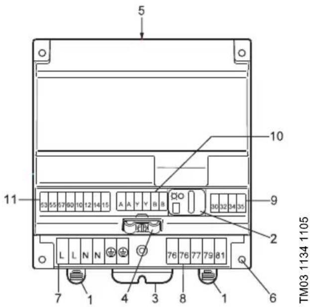
Fig. 1 IO 351 A
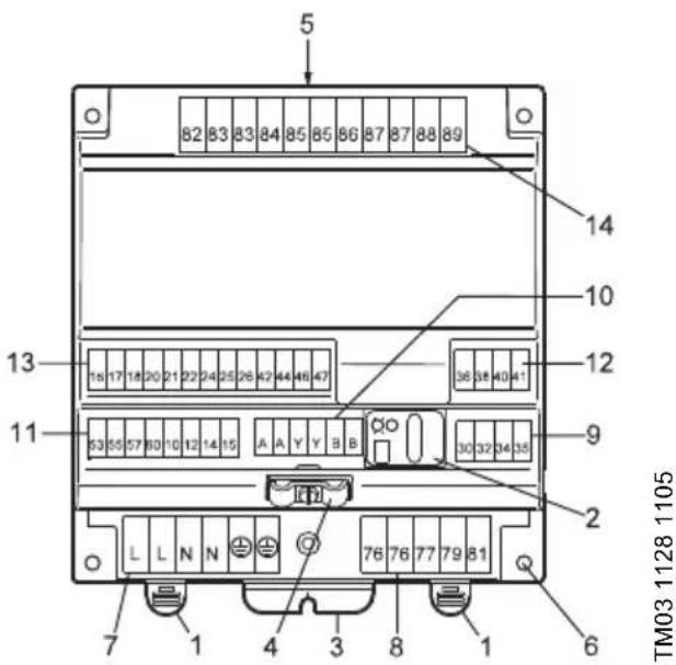
Fig. 2 IO 351 B
Pos. Description
| 1 DIN rail locking tab | |
| 2 | Indicator lights and transmitter/receiver for communication with R100 |
| 3 Earth connection to cabinet | |
| 4 Cable clamp for GENIbus cables | |
| 5 Nameplate | |
| 6 Holes for mounting with screws | |
| 7 Terminals for voltage supply | |
| 8 Terminals for relay output | |
| 9 | Terminals for inputs for PTC sensor or thermal switch |
| 10 Terminals for GENIbus | |
| 11 Terminals for digital and analog inputs | |
| Pos. Description | |
| 1 DIN rail locking tab | |
| 2 | Indicator lights and transmitter/receiver for communication with R100 |
| 3 Earth connection to cabinet | |
| 4 Cable clamp for GENIbus cables | |
| 5 Nameplate | |
| 6 Holes for mounting with screws | |
| 7 Terminals for voltage supply | |
| 8 Terminals for relay output | |
| 9 | Terminals for inputs for PTC sensor or thermal switch |
| 10 Terminals for GENIbus | |
| 11 Terminals for digital and analog inputs | |
| 12 | Terminals for Inputs for PTC sensor or thermal switch |
| 13 | Terminals for digital inputs and analog outputs |
| 14 Terminals for relay output | |
2. Identification
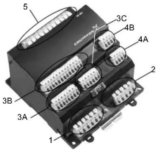
The variant (A or B) is stated on the nameplate on the back. It can also be identified by the number of terminal blocks. IO 351 A has five terminal blocks, 351 B has eight, see fig. 1 and 2.
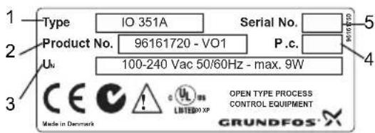
Fig. 3 Nameplate IO 351 A
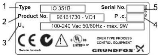
Fig. 4 Nameplate IO 351 B
Pos. Description
| 1 Type designation | |
| 2 Product/version number | |
| 3 | Permissible supply voltage, frequency and maximum power consumption |
| 4 Production code (year, week) | |
| 5 Serial number | |
2.1 Type key
Code Meaning IO 3 5 1 B
| IO Input-output unit |
| 35 Controller series |
| 1 Model number |
| A For pumps with fixed speed |
| B For pumps with fixed speed and pumps controlled by external frequency converters or as input-output module |
3. Installation
IO 351 is only intended for factory wiring.
Before installation check that the
- variant corresponds to the one ordered.
• IO 351 is suitable for the supply voltage and frequency on the installation site.
• IO 351 has not been damaged during transportation.

Warning
Before installing the IO 351, make sure that the electricity supply has been switched off and that it cannot be accidentally switched on.
The installation must be carried out by authorized personnel in accordance with local regulations.
All safety regulations must be observed on the installation site.

Warning
The terminals L and N as well as 76-81 and 82-89 may be connected to dangerous contact voltage. External control voltage from other groups may occur.

Warning
All wires to units outside the control panel must be of the type H05VV-F according to CENELEC HD21 (to avoid injury from touching wires).

Warning
The installation must incorporate a circuit breaker in order to switch off the mains supply. It must be close to the IO 351 and easily accessible for the operator. It must be marked as circuit breaker for IO 351. The circuit breaker must be according to IEC 60947-1 and IEC 60947-3.

Warning
The terminals are only separated with basic insulation. Therefore, do not connect a PELV circuit to a terminal adjacent to a terminal connected to live voltage.
PELV circuits and live wires must be separated with double or reinforced insulation.
3.1 Location
IO 351 is designed for indoor installation. For outdoor installation the IO 351 must be mounted in a suitable panel.
3.2 Enclosure class
In order to reduce the external pollution level to maximum 2, the IO 351 must be installed in a protecting environment with minimum IPX4 enclosure according to IEC 60529. The cabinet must be of a flame-retardant material.
3.3 Terminals
All terminals are suitable for conductors of 0.5 to 2.5 mm ^4 or AWG 20-13.
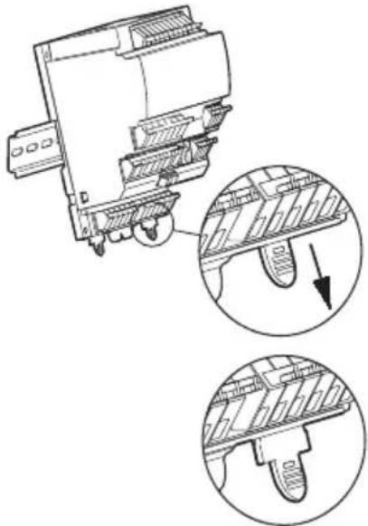
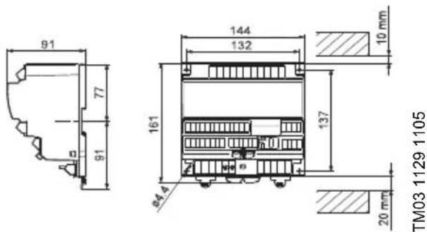
3.4 Mounting
IO 351 is prepared for mounting on a 35 mm DIN rail (EN 50022). Recommended height: 7.5 mm.
Module dimensions and minimum clearance above and under the module, see 13. Dimensions.
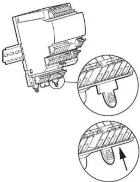
- Fit the IO 351 by hooking the top on the DIN rail and holding the bottom against the rail.
- Push the locking tabs (pos. 1) into the module as shown in fig. 5.
- Connect the conductors, see 8. Overview of inputs and outputs.
If the modules are mounted vertically, it is recommended to fit an end stop on the DIN rail below the lowest module.
natural_image
Technical line drawing of a mechanical component with two magnified insets showing internal structure (no text or symbols)TM03 1130 1105
Fig. 5 Mounting on DIN rail
3.5 EMC-correct installation
IO 351 is usually mounted in a panel also containing a CU 351 and frequency converters, contactors and other power equipment. In order to ensure a faultless function, it is very important to install the electronic modules in an EMC-correct way:
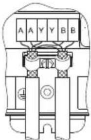
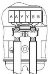
- Use screened cables for GENIbus. Connect the screen to the cable clamp of the module forward of the terminals AA, YY and BB.
TM03 1655 2505
Fig. 6 Screen fixed with cable clamp
Any isolating plastic tape between screen and sheath must be removed before mounting the cable in the cable clamp.
Signal conductors for digital and analog inputs and outputs should be screened, i.e. run the screen all the way to the IO 351 and connect it to frame with for instance a cable clamp.
Alternatively, the signal conductors in the panel may be unscreened if the panel is divided into a power and a low-voltage area. Unscreened signal conductors must not run in the power area, but exclusively in ducts in the low-voltage area.
- Do not twist screen ends, as this will destroy the screen effect at high frequencies. Use cable clamps.
- The module construction ensures a good electrical contact to the DIN rail. The DIN rail must therefore have a good connection to functional earth. If the module is mounted without a DIN rail by means of the four mounting holes (pos. 6), there must be a connection to functional earth through the fitting (pos. 3). See fig. 1 or 2.
- Use toothed washers and galvanically conducting mounting plates.
3.6 Allocation of address
| Address | |
| 1. pump module 31 | |
| 2. pump module 32 | |
| 1. input-output module 41 | |
| 2. input-output module 42 |
- Point the R100 against the IO 351 and press [OK]. See fig. 7.
- Press [>] to go to the menu INSTALLATION.
- Press [v] to get to Number (address).
- Set the address with [+] and [-] .
- Point the R100 against the IO 351 and press [OK].
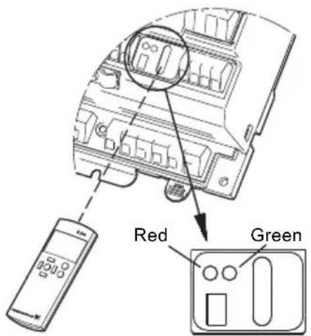
Fig. 7 R100 and indicator lights
TM03 1131 1105
4. Start-up
Start-up must be carried out by authorized personnel.

Warning
Prior to start up, read the installation and operating instructions for the product in question.
5. Functions of indicator lights
See fig. 7.
| Indication Description | |
| The green indicator light is off. | The electricity supply is interrupted. |
| The green indicator light flashes slowly (1 Hz). | The module is ready for operation, but there is no communication yet. |
| The green indicator light is permanently on. | The electricity supply is on, and the module is starting up. |
| The green indicator light flashes quickly (5 Hz). | The module is ready for operation, and IO 351 and CU 351 communicate. |
| The red indicator flashes. | IO 351 and R100 communicate. |
6. Technical data
Transient voltages typically present on the mains supply are category 2.
Altitudeabove sea level
Maximum 2000 m.
Ambient temperature
- During operation: 0^ to +50^ . (must not be exposed to direct sunlight).
• In stock: -20 °C to +60 °C. - During transportation: -20^ to +60^ .
Relative air humidity
From 5 % to 95 %.
Pollution degree
Category 2.
7. Electrical data
Supply voltage:
1 x 100-240 VAC ± 10 %, 50/60 Hz, PE (Class 1 equipment).
Back-up fuse:
Maximum 10 A. Both standard fuses as well as quick- and slow-blow fuses are suitable.
Short-circuit protection:
Use fuses that comply with IEC 60127.
USA and Canada (branch circuit protection): Use a UL/CSA listed non-time delay (high capacity) fuse that complies with the UL248 series or an inverse time circuit breaker that complies with UL489.
Fuse types RK1, RKS, J and CC are acceptable.
Power consumption:
Maximum 9 W.
7.1 Digital inputs
| Open circuit voltage: 24 VDC |
| Closed circuit current: 5 mA, DC |
| Frequency range: 0-4 Hz |
7.2 Analog inputs
| Input current and voltage: | 0-20 mA4-20 mA0-10 V |
| Tolerance: | ± 3.3 % of full scale |
| Repetitive accuracy: ± 1 % of full scale | |
| Input resistance, current: < 250 Ω | |
| Input resistance, voltage: > 50 kΩ ± 10 % | |
| Supply to sensor: | 24 V, maximum 50 mA, short-circuit protected |
7.3 Inputs for PTC sensor/thermal switch
For PTC sensors to DIN 44082. Thermal switches can also be connected.
| Open circuit voltage: 12 VDC ± 15 % |
| Closed circuit current: 2.6 mA, DC |
7.4 Digital outputs (relay outputs)
| Normally open contacts: C, NO |
| Maximum contact load: 240 VAC, 2 A |
| Minimum contact load: 5 VDC, 10 mA |
7.5 Analog outputs
All outputs are short-circuit protected.
| Output signal: 0-10 V +2/-0 % |
| Repetitive accuracy: ±5 % of full scale |
| Maximum output current: 2 mA |
7.6 Terminal groups
TM03 2110 3705
Fig. 8 Terminal groups
The terminals of the groups 3A, 3B and 3C are isolated from all other terminal groups by reinforced insulation, 2224 VAC.
| Group 1: Connection of supply voltage | |
| Group 2: Digital outputs 1-3 | |
| Group 3A, B, C: | Digital inputsAnalog inputs and outputs |
| Group 4A, B: | Inputs for PTC sensor or thermal switch |
| Group 5: Digital outputs 4-7 | |
All control terminals in groupe 3 are supplied with PELV voltage (Protective Extra-Low Voltage).
8. Overview of inputs and outputs
DI: Digital input
DO: Digital output
AO: Analog output
AI: Analog input
NO: Normally open contact
C: Common
| Group Terminal Designation Data Diagram | |||
| 1 | L Connection of phase conductor | 1 x 100-240 VAC ± 10 %, 50/60 Hz | 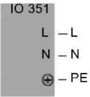 |
| N Connection of neutral conductor | |||
| PE Connection to protective earth | |||
| 2 | 76 DO 1, 2, 3, C | Relay contact, NO.Maximum load: 240 VAC, 2AMinimum load: 5 VDC, 10 mA | 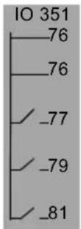 |
| 76 DO 1, 2, 3, C | |||
| 77 DO 1, NO | |||
| 79 DO 2, NO | |||
| 81 DO 3, NO | |||
| 3A | 53 + 24 V Supply to sensor. Maximum 50 mA | 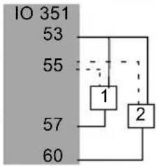 | |
| 55 GND | |||
| 57 AI 1 | Input for analog signal, 0/4-20 mA or 0-10 V | ||
| 60 AI 2 | |||
| All terminals (except mains terminals) must only be connected to voltages not exceeding 16 Vrms and 22.6 Vpeak or 35 VDC. | |||
| 3A | 10 DI 1 | Digital input | 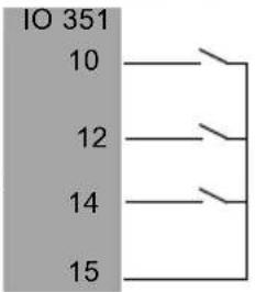 |
| 12 DI 2 | |||
| 14 DI 3 | |||
| 15 GND | |||
| All terminals (except mains terminals) must only be connected to voltages not exceeding 16 Vrms and 22.6 Vpeak or 35 VDC. | |||
| 3C | A RS485 A | GENIbus (internal)(Fix the screen with a cable clamp.) | 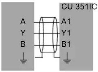 |
| A RS485 A | |||
| Y RS485 GND* | |||
| Y RS485 GND* | |||
| B RS485 B | |||
| B RS485 B | |||
| ± Functional earth | |||
* GND is isolated from other ground connections.
| Group Terminal Designation Data Diagram | |||
| 4A | 30 PTC 1 | Input for PTC sensor or thermal switch | 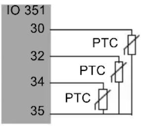 |
| 32 PTC 2 | |||
| 34 PTC 3 | |||
| 35 GND, PTC | |||
| Make jumpers if no PTC sensor or thermal switch is connected. | |||
| All terminals (except mains terminals) must only be connected to voltages not exceeding 16 Vrms and 22.6 Vpeak or 35 VDC. | |||
| 3B** | 16 DI 4 Digital input | Digital input44 DI 8 | 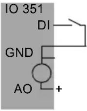 |
| 17 GND | |||
| 18 AO 4 Analog output, 0-10 V | |||
| 20 DI 5 Digital input | |||
| 21 GND | |||
| 22 AO 5 Analog output, 0-10 V | |||
| 24 DI 6 Digital input | |||
| 25 GND | |||
| 26 AO 6 Analog output | |||
| 42 DI 7 | |||
| 46 DI 9 | |||
| 47 GND | |||
| 4B** | 36 PTC 4 | Input for PTC sensor or thermal switch | 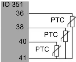 |
| 38 PTC 5 | |||
| 40 PTC 6 | |||
| 41 GND, PTC | |||
| Make jumpers if no PTC sensor or thermal switch is connected. | |||
| All terminals (except mains terminals) must only be connected to voltages not exceeding 16 Vrms and 22.6 Vpeak or 35 VDC. | |||
| 5** | 82 DO 4 NO | Relay contact | 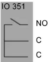 |
| 83 DO 4 C | |||
| 83 DO 4 C | |||
| 84 DO 5 NO | |||
| 85 DO 5 C | |||
| 85 DO 5 C | |||
| 86 DO 6 NO | |||
| 87 DO 6 C | |||
| 87 DO 6 C | |||
| 88 DO 7 NO | |||
| 89 DO 7 C | |||
** Only IO 351 B.
9. GENIbus
CU 351 and IO 351 and E-pumps communicate by means of GENIbus.
10. Service
IO 351 cannot be serviced. If the module is faulty, it must be replaced. See section 12. Replacement of IO 351.
11. Maintenance
The IO 351 is maintenance-free during normal use and operation. IO 351 must only be cleaned with a dust-free cloth.
12. Replacement of IO 351
- Switch off the power supply to the IO 351.
- Switch off the power supply to components with external supply.
- Mark the individual conductors with the numbers of the corresponding terminals.
- Disconnect all conductors.
- Pull the locking tabs free of the rail, see fig. 9. The module can now be lifted off the rail.
- Mount the new IO 351, see section 3.4 Mounting.
natural_image
Technical line drawing of a mechanical component with two circular insets showing internal components (no text or symbols)TM03 1133 1105
Fig. 9 Rail locking tabs
13. Dimensions
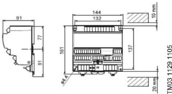
Fig. 10 Dimensional sketch
14. Disposal
This product or parts of it must be disposed of in an environmentally sound way:
- Use the public or private waste collection service.
- If this is not possible, contact the nearest Grundfos company or service workshop.
The crossed-out wheelie bin symbol on a product means that it must be disposed of separately from household waste. When a product marked with this symbol reaches its end of life, take it to a collection point designated by the local
waste disposal authorities. The separate collection and recycling of such products will help protect the environment and human health.
natural_image
Technical line drawing of a mechanical component with two circular insets showing internal components (no text or symbols)natural_image
Technical line drawing of a mechanical device with two circular insets showing internal components (no text or symbols)natural_image
Technical line drawing of a mechanical component with two magnified views showing internal structure (no text or symbols)TM03 1130 1105
Obr. 5 Instalace na liště DIN.
3.5 Instalace v souladu s EMC
natural_image
Technical line drawing of a mechanical device with two circular insets showing internal components (no text or symbols)Obr. 9 Pojistné jazýčky pro instalaci na lištu
TM03 1133 1105
13. Rozměry
natural_image
Technical line drawing of a mechanical component with two magnified views showing internal structure (no text or symbols)natural_image
Technical line drawing of a mechanical device with two circular insets showing internal components (no text or symbols)natural_image
Technical line drawing of a mechanical component with two magnified insets showing internal components (no text or symbols)natural_image
Technical line drawing of a mechanical device with two circular insets showing internal components (no text or symbols)Fig. 9 Skinnelås
TM03 1133 1105
13. Mål
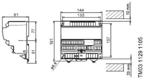
Fig. 10 Målskitse
14. Bortskaffelse
natural_image
Technical line drawing of a mechanical component with two circular insets showing internal components (no text or symbols)TM03 1130 1105
Joonis 5 Paigaldamine DIN-liistule
3.5 EMC-korrektne paigaldamine
natural_image
Technical line drawing of a mechanical device with two circular insets showing internal components (no text or symbols)natural_image
Technical line drawing of an electronic component with two circular insets showing internal structure and a directional arrow (no text or symbols)natural_image
Technical line drawing of a mechanical device with two circular insets showing internal components (no text or symbols)natural_image
Technical line drawing of a mechanical component with two magnified views showing internal structure (no text or symbols)natural_image
Technical line drawing of a mechanical device with two circular insets showing internal components (no text or symbols)natural_image
Technical line drawing of a mechanical device with two circular insets showing internal components (no text or symbols)natural_image
Technical line drawing of a mechanical device with two circular insets showing internal components (no text or symbols)TM03 1133 1105
natural_image
Technical line drawing of a mechanical component with two magnified views showing internal structure (no text or symbols)natural_image
Technical line drawing of a mechanical device with two circular insets showing internal components (no text or symbols)natural_image
Technical line drawing of a mechanical device with two circular insets showing internal components (no text or symbols)TM03 1130 1105
Slika 5 Montiranje na DIN vodilici
3.5 EMC - pravilna montaža
IO 351 se najčešće montira na ploču na kojoj se nalazi i CU 351, te frekventni pretvarač, vodiči i druga oprema. Kako biste osigurali rad bez smetnji, važno je ispravno montirati električne module prema EMC:
- za GENIbus koristite zakriljene kabele Spojite zakriljenje sa sponom kabela modula na stezaljke AA, YY i BB;
TM03 1655 2505
Slika 6 Zakriljenje sa sponom kabela
Uklonite sve izolacijske plastične trake između zakriljenja i plašta prije montiranja kabela u kabelske spone.
Vodiči signala za digitalne i analogne ulaze i izlaze moraju biti zakriljeni, tj. provucite zakriljeni kabel sve do IO 351 i spojite na okvir sa sponom kabela.
natural_image
Technical line drawing of a mechanical device with two circular insets showing internal components (no text or symbols)natural_image
Technical line drawing of a mechanical component with two circular insets showing internal components (no text or symbols)TM03 1130 1105
natural_image
Technical line drawing of a mechanical component with two circular insets showing internal structure details (no text or symbols)- ábra Rögzítő fülek
13. Méretek

- ábra Méret rajz
14. Hulladékkezelés
natural_image
Technical line drawing of a mechanical component with two circular insets showing internal structures (no text or symbols)natural_image
Technical line drawing of a mechanical device with two circular insets showing internal components (no text or symbols)natural_image
Technical line drawing of a mechanical component with two circular insets showing internal components (no text or symbols)natural_image
Technical line drawing of a mechanical device with two circular insets showing internal components (no text or symbols)natural_image
Technical line drawing of a mechanical component with two circular insets showing internal structures (no text or symbols)natural_image
Technical line drawing of a mechanical device with two circular insets showing internal components (no text or symbols)natural_image
Technical line drawing of a mechanical component with two magnified views showing internal structure (no text or symbols)Slika 7 R100 i indikacione lampice
TM03 1131 1105
4. Puštanje u rad
Puštanje u rad mora biti obavljeno od strane stručnog lica.

Upozorenje
Pre puštanja u rad pročitati uputstva za instalaciju i rad proizvoda koji je u pitanju.
5. Funkcije indikacionih lampica
Videti sliku 7.
| Indikacija Opis | |
| Zelena indikaciona lampica ne svetli. | Dovod struje je ometen. |
| Zelena indikaciona lampica lagano trepće (1 Hz). | Modul je spreman za rad ali još nije uspostavljena komunikacija. |
| Zelena indikaciona lampica stalno svetli. | Dovod struje je uključen i modul počinje da radi. |
| Zelena indikaciona lampica brzo trepće (5 Hz). | Modul je spreman za rad, IO 351 i CU 351 komuniciraju. |
| Crvena idikaciona lampica trepće. | IO 351 i R100 komuniciraju. |
6. Tehnički podac
Na glavnom dovodu struje privremene voltaže uglavnom predstavljaju kategoriju 2.
natural_image
Technical line drawing of a mechanical component with two circular insets showing internal structural details (no text or symbols)Slika 9 Zalisci za zaključavanje šinei
TM03 1133 1105
13. Dimenzije

Slika 10 Skica dimenzija
14. Uklanjanje
Ovaj proizvod ili njegovi delovi moraju biti uklonjeni na ekološki ispravan način:
- Koristiti lokalna javna ili privatna preduzeća za odlaganje smeća.
- Ako to nije moguće, kontaktirati najbližu Grundfos kompaniju ili servisnu radionicu.
natural_image
Technical line drawing of a mechanical component with two circular insets showing internal components (no text or symbols)natural_image
Technical line drawing of a mechanical device with two circular insets showing internal components (no text or symbols)Рис. 9 Фиксаторы
TM03 1133 1105
natural_image
Technical line drawing of a mechanical component with two circular insets showing internal components (no text or symbols)natural_image
Technical line drawing of a mechanical device with two circular insets showing internal components (no text or symbols)natural_image
Technical line drawing of a mechanical component with two circular insets showing internal components (no text or symbols)TM03 1130 1105
Skica 5 Montaža na DIN vodilo
3.5 EMC-ustrezna instalacija
natural_image
Technical line drawing of a mechanical component with two circular insets showing internal structure details (no text or symbols)natural_image
Technical line drawing of a mechanical device with two circular insets showing internal components (no text or symbols)TM03 1130 1105
Obr. 5 Pripevnenie na držiak DIN
3.5 Správna montáž
natural_image
Technical line drawing of a mechanical device with two circular insets showing internal components (no text or symbols)natural_image
Technical line drawing of a mechanical component with two magnified views showing internal structure (no text or symbols)natural_image
Technical line drawing of a mechanical device with two circular insets showing internal components (no text or symbols)natural_image
Technical line drawing of a mechanical component with two circular insets showing internal components (no text or symbols)图 5 安装在 DIN 导轨上
3.5 EMC 正确安装
natural_image
Technical line drawing of a mechanical component with two magnified insets showing internal structure details (no text or symbols)图 9 导轨锁定件
13. 尺寸规格

图 10 尺寸图
14. 回收处理
GB: EU declaration of conformity
We, Grundfos, declare under our sole responsibility that the product IO351, to which the declaration below relates, is in conformity with the Council Directives listed below on the approximation of the laws of the EU member states.
This EU declaration of conformity is only valid when published as part of the Grundfos installation and operating instructions (publication number 96604440 0217).
Bjerringbro, 18/1/2017

Svend Aage Kaae
Director
Grundfos Holding A/S
Poul Due Jensens Vej 7
8850 Bjerringbro, Denmark
Person authorised to compile the technical file and empowered to sign the EU declaration of conformity.
EAC
Bosnia and Herzegovina
GRUNDFOS Sarajevo
Zmaja od Bosne 7-7A,
BH-71000 Sarajevo
Phone: +387 33 592 480
Telefax: +387 33 590 465
www.ba.grundfos.com
e-mail: grundfos@bih.net.ba
Brazil
BOMBAS GRUNDFOS DO BRASIL
Av. Humberto de Alencar Castelo
Branco, 630
CEP 09850 - 300
São Bernardo do Campo - SP
Phone: +55-11 4393 5533
Telefax: +55-11 4343 5015
Bulgaria
Grundfos Bulgaria EOOD
Slatina District
Iztochna Tangenta street no. 100
BG - 1592 Sofia
Tel. +359 2 49 22 200
Fax. +359 2 49 22 201
email: bulgaria@grundfos.bg
Canada
GRUNDFOS Canada Inc.
2941 Brighton Road
Oakville, Ontario
L6H 6C9
Phone: +1-905 829 9533
Telefax: +1-905 829 9512
China
GRUNDFOS Pumps (Shanghai) Co. Ltd.
10F The Hub, No. 33 Suhong Road
Minhang District
Shanghai 201106
PRC
Phone: +86 21 612 252 22
Telefax: +86 21 612 253 33
COLOMBIA
GRUNDFOS Colombia S.A.S.
GRUNDFOS Sales Czechia and
Slovakia s.r.o.
Čajkovského 21
779 00 Olomouc
Phone: +420-585-716 111
Denmark
GRUNDFOS DK A/S
Martin Bachs Vej 3
DK-8850 Bjerringbro
Tlf.: +45-87 50 50 50
Telefax: +45-87 50 51 51
E-mail: info_GDK@grundfos.com
www.grundfos.com/DK
Estonia
Unit 1, Ground floor
Siu Wai Industrial Centre
29-33 Wing Hong Street &
68 King Lam Street, Cheung Sha Wan
Kowloon
Phone: +852-27861706 / 27861741
Telefax: +852-27858664
Hungary
118 Old Mahabalipuram Road
Thoraipakkam
Chennai 600 096
Phone: +91-44 2496 6800
Indonesia
PT. GRUNDFOS POMPA
Graha Intirub Lt. 2 & 3
Jln. Cililitan Besar No.454. Makasar,
Jakarta Timur
ID-Jakarta 13650
Phone: +62 21-469-51900
Telefax: +62 21-460 6910 / 460 6901
Ireland
GRUNDFOS (Ireland) Ltd.
Unit A, Merrywell Business Park
Ballymount Road Lower
Dublin 12
Phone: +353-1-4089 800
Telefax: +353-1-4089 830
Italy
GRUNDFOS Pompe Italia S.r.l.
Via Gran Sasso 4
6th Floor, Aju Building 679-5
Yeoksam-dong, Kangnam-ku, 135-916
Seoul, Korea
Phone: +82-2-5317 600
Telefax: +82-2-5633 725
Latvia
SIA GRUNDFOS Pumps Latvia
Deglava biznesa centrs
7 Jalan Peguam U1/25
Glenmarie Industrial Park
40150 Shah Alam
Selangor
Phone: +60-3-5569 2922
Telefax: +60-3-5569 2866
Mexico
Boulevard TLC No. 15
GRUNDFOS Netherlands
Veluwezoom 35
1326 AE Almere
Postbus 22015
1302 CA ALMERE
Tel.: +31-88-478 6336
Telefax: +31-88-478 6332
E-mail: info_gnl@grundfos.com
New Zealand
GRUNDFOS Pumps NZ Ltd.
17 Beatrice Tinsley Crescent
North Harbour Industrial Estate
Albany, Auckland
Phone: +64-9-415 3240
Telefax: +64-9-415 3250
Norway
GRUNDFOS Pumper A/S
Strømsveien 344
Postboks 235, Leirdal
N-1011 Oslo
Tlf.: +47-22 90 47 00
Telefax: +47-22 32 21 50
Poland
GRUNDFOS Pompy Sp. z o.o.
ul. Klonowa 23
16 Lascelles Drive, Meadowbrook Estate
1609 Germiston, Johannesburg
Tel.: (+27) 10 248 6000
Fax: (+27) 10 248 6002
E-mail: lgradidge@grundfos.com
Spain
7 Floor, 219 Min-Chuan Road
Taichung, Taiwan, R.O.C.
Phone: +886-4-2305 0868
Telefax: +886-4-2305 0878
Thailand
GRUNDFOS (Thailand) Ltd.
92 Chaloem Phrakiat Rama 9 Road,
Dokmai, Pravej, Bangkok 10250
Phone: +66-2-725 8999
Telefax: +66-2-725 8998
Turkey
GRUNDFOS POMPA San. ve Tic. Ltd. Sti.
United Arab Emirates
GRUNDFOS Gulf Distribution
P.O. Box 16768
Jebel Ali Free Zone
Dubai
Phone: +971 4 8815 166
Telefax: +971 4 8815 136
United Kingdom
GRUNDFOS Pumps Ltd.
Grovebury Road
Leighton Buzzard/Beds. LU7 4TL
Phone: +44-1525-850000
Telefax: +44-1525-850011
U.S.A.
GRUNDFOS Pumps Corporation
9300 Loiret Blvd.
Lenexa, Kansas 66219
Phone: +1-913-227-3400
Telefax: +1-913-227-3500
Uzbekistan
Grundfos Tashkent, Uzbekistan The Representative Office of Grundfos Kazakhstan in Uzbekistan
38a, Oybek street, Tashkent