CIM 060 - Pump Grundfos - Free user manual and instructions
Find the device manual for free CIM 060 Grundfos in PDF.

| Product Type | Pump Communication Interface (CIM 060) |
| Brand | Grundfos |
| Model | CIM 060 |
| Dimensions (H x W x D) | 120 mm x 80 mm x 35 mm |
| Weight | 0.2 kg |
| Power Supply | 24 V DC |
| Communication Protocols | Modbus RTU, Profibus DP, BACnet |
| Main Functions | Remote monitoring, control, and data logging for pump systems |
| Maintenance | Clean with dry cloth; no user-serviceable parts inside |
| Safety | Install in accordance with local electrical codes; disconnect power before servicing |
| Spare Parts | No spare parts available; replace unit if faulty |
| General Information | Designed for use with Grundfos pumps; operating temperature 0-50°C |
Frequently Asked Questions - CIM 060 Grundfos
User questions about CIM 060 Grundfos
0 question about this device. Answer the ones you know or ask your own.
Ask a new question about this device
Download the instructions for your Pump in PDF format for free! Find your manual CIM 060 - Grundfos and take your electronic device back in hand. On this page are published all the documents necessary for the use of your device. CIM 060 by Grundfos.
USER MANUAL CIM 060 Grundfos
Installation and operating instructions
flowchart
graph TD
    A["WWW"] --> B["Device 1"]
    A --> C["Device 2"]
    A --> D["Device 3"]
    A --> E["Device 4"]
    A --> F["Device 5"]
    A --> G["Device 6"]
    A --> H["Device 7"]
    A --> I["Device 8"]
    A --> J["Device 9"]
    A --> K["Device 10"]
    A --> L["Device 11"]
    A --> M["Device 12"]
    A --> N["Device 13"]
    A --> O["Device 14"]
    A --> P["Device 15"]
    A --> Q["Device 16"]
    A --> R["Device 17"]
    A --> S["Device 18"]
    A --> T["Device 19"]
    A --> U["Device 20"]
Grundfos Remote Management
English (GB)
Installation and operating instructions....4
Dansk (DK)
Original installation and operating instructions.
CONTENTS
| Page | |
| 1. Symbols used in this document | 4 |
| 2. Definitions and abbreviations | 4 |
| 3. Introduction | 5 |
| 4. Quick start-up | 7 |
| 5. Preparing the hardware for installation | 7 |
| 5.1 Preparing the SIM card | 7 |
| 6. Log-on to the GRM | 8 |
| 6.1 Navigation | 8 |
| 7. GRM data communication | 11 |
| 8. Overview | 12 |
| 9. Schedule for alarm distribution | 13 |
| 10. Reports | 15 |
| 11. Event log | 16 |
| 12. Service | 17 |
| 13. Admin, user administration | 18 |
| 14. Alarms | 19 |
| 14.1 Heartbeat | 19 |
| 14.2 Power supply failure, operating on battery | 19 |
| 15. Multi-purpose IO module | 20 |
| 16. GSM LED of the CIM 270 (left) | 22 |
| 17. GENIbus LED of the CIM 270 (right) | 23 |
| 18. Fault finding | 23 |
1. Symbols used in this document

Warning
If these safety instructions are not observed, it may result in personal injury!
Caution
If these safety instructions are not observed, it may result in malfunction or damage to the equipment!
Note
Notes or instructions that make the job easier and ensure safe operation.
- Definitions and abbreviations
| CIM 270 | Communication Interface Module (GPRS data logger). |
| CIU 27X Communication Interface Unit. | |
| GENIbus | Proprietary Grundfos fieldbus standard. |
| GRM Grundfos Remote Management. | |
| GPRS General Packet Radio Service. | |
| GSM | Global System for Mobile communications. |
| IMEI | International Mobile Equipment Identity. |
| IO module | Multi-purpose IO module in CIU 27X unit. |
| LED Light-Emitting Diode. | |
| PIN | Personal Identification Number (SIM cards). |
| SIM | SIM card, Subscriber Identity Module. |
3. Introduction
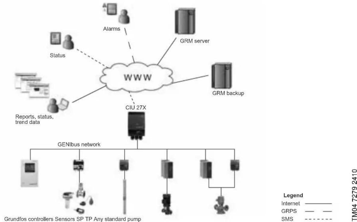
Grundfos Remote Management is an internet-based remote monitoring, management and reporting system for pump installations. It provides remote access to data from pumps, pump controllers and auxiliary equipment like sensors and meters. Data from pump installations is transferred to a central database and published to subscribers on a secure web server. Users have access to data from pump installations that are registered to their own Account.
flowchart
graph TD
    A["WWW"] --> B["GRM server"]
    A --> C["CIU 27X"]
    A --> D["GRM backup"]
    A --> E["Alarms"]
    A --> F["Status"]
    A --> G["Reports, status, trend data"]
    A --> H["GenIbus network"]
    H --> I["Grundfos controllers Sensors SP TP Any standard pump"]
    style A fill:#f9f,stroke:#333
    style B fill:#ccf,stroke:#333
    style C fill:#cfc,stroke:#333
    style D fill:#fcc,stroke:#333
    style E fill:#cff,stroke:#333
    style F fill:#ffc,stroke:#333
    style G fill:#fcc,stroke:#333
    style H fill:#cfc,stroke:#333
    style I fill:#fcc,stroke:#333
    style_J["Internet"] -.-> K["GRPS"] -.-> L["SMS"] -.-> M["TM04 7279 2410"]
Fig. 1 Grundfos Remote Management
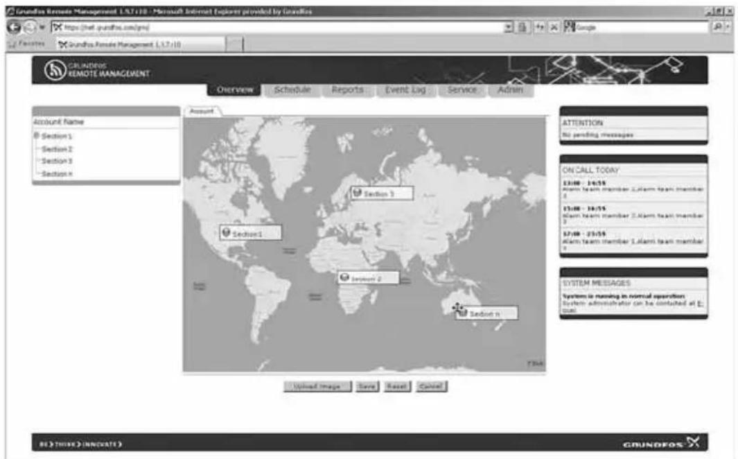
A fully configured system Account contains maps and system drawings that provide an overview of your pump installations. It also has a Schedule to direct alarms to users when they are on duty, and it contains a Service log for all your pumps. This user manual guides you through the process of configuring your Account and connecting pump installations to your Account.
A fully configured Grundfos Remote Management system appears from fig. 2.
text_image
Grundus Remote Management 1.6.7.183 - Microsoft Internet Explorer provided by Oracle https://net.surdhu.com/pts/ Google Grundus Remote Management 1.9.2.183 COUNBPOS REMOTE MANAGEMENT Data Used Schedule Reports Event Log Service Actions Grundus Demo Company Resistors Stooler Commercial Buildings Net water circulation Mail ventilation Process Water Treatment Cyberversible Systems SF NP204 Works Water Systems DC PUST demo 1 DC PUST demo 2 Deculated Controls Account Work Water... Commercial... Systems... System Messages System is running in normal operation. System administrator can be contacted at 5 pm ATTENTION Communication fault, inc.. Dry running Leakage Current ON CALL TODAY ISSUE - 21:518 Downloaded ReadOnly DemutileReadOnly ISSUE - 21:518 Description ReadOnly ISSUE - 21:518 Press Report/Issue Translation SYSTEM MESSAGESFig. 2 Example of an Account in Grundfos Remote Management
In the following, the tabs at the top of the user interface will be described in the order that the system is to be set up.
To get started using the system, we recommend you to read these instructions and carefully follow the setup procedure.
Other relevant documentation
Separate installation and operating instructions are available for the hardware:
• CIM 2XX GSM module (CIM 270)
• CIU – Communication Interface Unit (CIU 27X)
- Multi-purpose IO module in CIU 27X.
Note
We recommend you not to use Grundfos Remote Management as the only means of monitoring and control in systems where malfunction for a short period of time has severe consequences. The system is never more reliable than the GSM network used for data communication.
The functionality of Grundfos Remote Management is continually improved and enhanced. Information about new features is found online in the system.
This manual contains all the information you need for initial setup of your user Account in Grundfos Remote Management.
4. Quick start-up
The fast way to bring a new installation online is to follow the steps below:
- Insert your SIM card into a mobile phone, and set the PIN code to 4321.
- Make sure that the SIM card is able to acquire a signal from the network operator you expect it to use.
-
Be sure that you have noted the following:
-
Mobile phone number of the SIM card.
- IMEI number of the CIM 270.
The number appears from a silvery sticker inside and on the outside of the box the CIU 27X or CIM 270 was delivered in.
- If you use a CIU 27X, connect the GENIbus network and the power supply.
- See installation and operating instructions for the CIU – Communication Interface Unit and the quick guide for the CIU unit.
- If any sensors or meters are used and are to be monitored using the built-in multi-purpose IO module, see installation and operating instructions for Multi-purpose IO module in CIU 27X.
- Insert the SIM card into the CIM 270, and switch on the power supply.
- Check that the CIM 270 has acquired a network.
– See section 5.1 Preparing the SIM card.
- The yellow LED to the left will first flash rapidly (1-second intervals). Once a network has been acquired, the LED will flash slowly (3-second intervals).
- Log on to the GRM server, and complete the four-step installation wizard.
– See section 6. Log-on to the GRM. - Check that the GENIbus network is configured correctly. When the installation wizard is completed successfully, the LED to the right will change from permanently red to permanently green.
5. Preparing the hardware for installation
Guide to the electrical installation of the following hardware:
• CIM 270 (GPRS data logger).
- See installation and operating instructions for the CIM 2XX GSM module.
• CIU 27X with multi-purpose IO module.
- See installation and operating instructions for Multi-purpose IO module in CIU 27X and the quick guide for the CIU unit.
The CIM 270 GRM module is fitted in the CIU unit and is used to establish external communication to the GRM server.
Once the CIM 270 or CIU 27X has been installed, the SIM card must be prepared for installation.
5.1 Preparing the SIM card
During initial setup of a new CIM 270, the PIN code of the SIM card must be set to 4321.
- Insert the SIM card into a mobile phone, and find the function "Change PIN code" in the settings menu of your phone. The SIM card must have the PIN code 4321 at this point. Otherwise it will not be able to connect to a GSM network.
Note
During the online installation procedure, it is possible to set a new PIN code for the SIM card.
- Check that a connection to the GSM network can be established.
- Insert the SIM card into the CIM 270, and switch on the power supply.
- Observe the network indicator LED. See fig. 3. After a few moments, the flashing sequence should change from fast to slow. See section 16. GSM LED of the CIM 270 (left).
No GSM network:

Connection established:

natural_image
Black industrial electrical device with three ports and a label (no readable text or symbols)TM04 2594 2508
Fig. 3 Flashing sequence
The phone and IMEI numbers have to be used later on in the installation process. Therefore, we recommend you to make a note of the phone number of the SIM card and the IMEI number of the CIM 270. You are now ready to register the CIM 270 on the GRM server and to set up the application you want to have monitored by the GRM system.
6. Log-on to the GRM
To log on to the GRM server system, go to https://remotemanagement.grundfos.com.
You will be prompted for user name and password.
Current users of the Grundfos Extranet can log on with their Extranet user name and password. New users will receive an e-mail with log-on details.
If you do not have a user name and a password, contact your local Grundfos company, or send an e-mail to
remote-management@grundfos.com.
When you log on for the first time, a navigation tree will appear. See fig. 4.
The basic steps in setting up an Account are described in the following section.
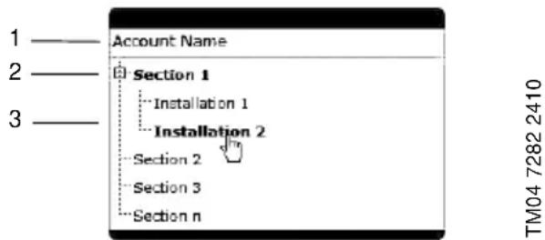
6.1 Navigation
To provide an overview of the installations monitored by the GRM system, a navigation tree is used.
text_image
Account Name 1 ———— 2 ———— 3 ———— Section 1 Installation 1 Installation 2 Section 2 Section 3 Section n TM04 7282 2410Fig. 4 Navigation tree
The navigation tree is divided into three levels:
| Pos. Level | ||||||
| 1 Account | ||||||
| 2 Section | ||||||
| 3 | l | n | s | t | a | l |
6.1.1 Account level
At the Account level, you will find the name and details of your Account.
6.1.2 Section level
At the Section level, it is possible to create several Sections. Sections are logical groups of one or more Installations.
At the Installation level, you will find the devices that are monitored. An Installation is defined by a modem monitoring one or more bus devices or sensors.
Sections could, for example, reflect a geographical segmentation of the entire monitored network or segmentation according to area of expertise or responsibility of a group of persons.
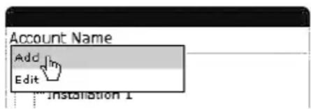
Adding a Section
Right-click the Account name, and click Add to add a Section.
text_image
Account Name Add Edit Installation 1Fig. 5 Adding a Section
When the Section is created, you can add an Installation to the Section.
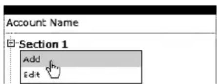
6.1.3 Installation level
An Installation is always added to a Section and consists of a modem and a number of monitored devices, normally a CIM 270 and at least one GENIbus device (Grundfos pump, pump controller or IO module).
Adding an installation i o n
Right-click the Section name, and click Add to add an Installation.
text_image
Account Name Section 1 Add EditFig. 6 Adding an Installation
The setup of an Installation is a four-step procedure:
- Create Installation.
- Set up Installation.
- Configure and connect Installation.
- Configure alarms and warnings.
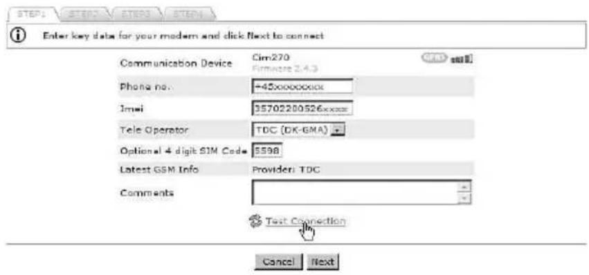
Step 1: Create Installation
- Enter the phone number of the SIM card (+ (country prefix) (phone number)).
- Enter the IMEI number of the CIM 270 (XXXXXXXXXXXXXX).
- Select the mobile data service provider.
- Enter an optional PIN code. This code will replace the default PIN code that was set during initial setup of the CIM 270.
text_image
STEP1 STEP2 STEP3 STEP4 Enter key data for your modem and click Next to connect Communication Device Cim270 (Firmware 2.4.3) GMS Phone no. -45xxxxxxx000 Email 95702200526xxxxx Tele Operator TDC (DK-GMA) Optional 4 digit SIM Code 5598 Latest GSM Info Provider: TDC Comments Text Connection Cancel NextFig. 7 Establishing connection
TM04 7285 2410 TM04 7286 2410
Click "Test connection". The test will take a few minutes. The server configures the CIM 270 for use in the GRM system.
If the server has connected successfully, you are notified and can proceed to Step 2: Name and type.
If the server does not get a response from the CIM 270 within two minutes, the attempt to connect will time out, and you will get a fault notification. See section 18. Fault finding.
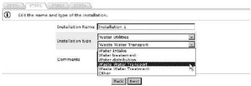
Step 2: Name and type
Enter a name for your Installation, and select the application type that best characterises the Installation. This will provide the system with information on, for example, the type of report that is relevant for this Installation.
text_image
Edit the name and type of the installation. Installation Name Installation 1 Installation type Water Utilities Waste Water Transport Comments Water Intake Water treatment Water distribution Waste Water Transport Waste Water Treatment Other Back NextFig. 8 Name and type of installation
Step 3: Configure and connect Installation
Click "Discover devices" to initiate a scan of the network of GENIbus devices connected to the CIM 270. Once the scan is completed, you will see a list of connected devices (pumps, controllers or modules) together with their address in the network.
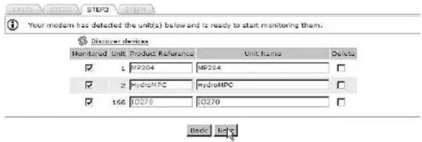
text_image
Your modem has detected the unit(s) below and is ready to start monitoring them. Discover devices Monitored Unit Product Reference Unit Name Delete ✓ L MP204 MP204 ✓ 2 HydroMPC HydroMPC ✓ 166 IO270 IO270 Back BackTM04 7287 2410
Fig. 9 Discovering GENIbus devices
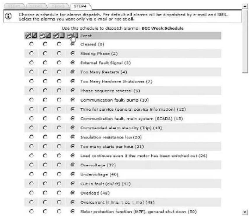
Step 4: Configure alarms and warnings
Alarms and warnings that can be received from each type of device on the monitored network will be listed. It is possible to select which alarms you want to receive and how they should be sent.
| Icon Description | |
| Both e-mail and SMS alarms have been disabled. | |
| An e-mail will be sent to the user when the alarm or warning is active. | |
| An SMS will be sent to the user when the alarm or warning is active. | |
| An e-mail and an SMS will be sent to the user when the alarm or warning is active. | |
text_image
Choose a schedule for alarms dispatch. Per default all alarms will be dispatched by e-mail and SMS. Select the alarms you want only via e-mail or not at all. Use this schedule to dispatch alarms: BCC Week Schedule Event C C C Cleared (0) C C C Missing Phase (2) C C C External Fault Signal (3) C C C Too Many Restarts (4) C C C Too Many Hardware Shutdowns (7) C C C Phase sequence reversal (9) C C C Communication fault, pump (10) C C C Time for service (general service information) (12) C C C Communication fault, main system (SCADA) (15) C C C Commanded alarm standby (Trip) (18) C C C Insulation resistance low (20) C C C Too many starts per hour (21) C C C Load continues even if the motor has been switched out (26) C C C Overvoltage (32) C C C Undervoltage (40) C C C Cut-in fault (dV/dt) (42) C C C Overload (48) C C C Overcurrent (LJing, Ldc, Lmo) (49) C C C Motor protection function (MPF), general shut down (50)TM04 7288 2410
Fig. 10 Selecting dispatch mode for alarms and warnings
When you click [Finish], the server will transmit your monitoring configuration to the CIM 270, and the installation is completed.
7. GRM data communication
This section describes how data communication and data collection work in Grundfos Remote Management. We distinguish between four different types of data:
- Sample Data: Data used to create trend curves.
• Event Data: Data that shows you what your installation is doing right now (actual status). - Alarm Data: A special type of Event Data that is sent instantly in the event of an alarm.
- Manage Commands: Commands you send from the web user interface when you want to remote-control or -configure a GENIbus device.
The CIM 270 is able to send/receive data using both SMS and GPRS traffic. However, there are some built-in rules that govern the priority and type of data connection used.
| Data type | Data connection | Description |
| Sample Data GPRS | Sample Data is stored in the CIM 270 and sent to the central server via GPRS at regular intervals. This data is the basis of trend curves and used in reports as well.The sample interval is normally 30 minutes. | |
| Event Data | GPRS and SMS | Event Data is real-time data. This data tells you what is going on in the installation right now.Event Data is collected and displayed when you establish a connection to the installation.If a GPRS connection cannot be established, Event Data is sent via SMS. |
| Alarm Data | SMS and GPRS | Alarm Data is a special type of Event Data. When a CIM 270 sends an alarm to the central server, it will also deliver a snapshot of Event Data present for that installation at the time the event occurred.If a GPRS connection cannot be established, Alarm Data is sent via SMS.The CIM 270 will continue to attempt to send an alarm to the central server until it has received acknowledgement from the server. |
| Manage Commands | GPRS only | A device can only be remote-controlled when a GPRS connection is established. This gives the highest possible degree of certainty that the command issued is received and carried out when expected. |
If you have received an alarm and want to analyse the cause of the alarm, do not click [Connect] until you have had a look at the Event Data at the time of the alarm.
8. Overview

text_image
Overview Schedule Reports Event Log Service AdminFig. 11 Overview
In this view, it is possible to insert images at Account and Section levels, for example maps and system drawings displaying the location and layout of pump installations.
Supported formats are *.png, *.jpg and *.gif. We recommend file sizes below 250 kb to optimise the performance of the web server. Largest permissible file size is 10 Mb.
text_image
Grundfos Remote Management L1.7-10 - Microsoft Internet Explorer provided by Grundfos https://grundfos.com/gms/ Grundfos Remote Management L1.7-10 CRLUNDERS REMOTE MANAGEMENT Overview Schedule Reports Event Log Service Admin Account Name Section 1 Section 2 Section 3 Section n Account Segment Segment 1 Segment 2 Segment n Segment 3 Segment 4 Segment 5 Segment 6 Segment 7 Segment 8 Segment 9 Segment 10 Segment 11 Segment 12 Segment 13 Segment 14 Segment 15 Segment 16 Segment 17 Segment 18 Segment 19 Segment 20 Segment 21 Segment 22 Segment 23 Segment 24 Segment 25 Segment 26 Segment 27 Segment 28 Segment 29 Segment 30 Segment 31 Segment 32 Segment 33 Segment 34 Segment 35 Segment 36 Segment 37 Segment 38 Segment 39 Segment 40 Segment 41 Segment 42 Segment 43 Segment 44 Segment 45 Segment 46 Segment 47 Segment 48 Segment 49 Segment 50 Segment 51 Segment 52 Segment 53 Segment 54 Segment 55 Segment 56 Segment 57 Segment 58 Segment 59 Segment 60 Segment 61 Segment 62 Segment 63 Segment 64 Segment 65 Segment 66 Segment 67 Segment 68 Segment 69 Segment 70 Segment 71 Segment 72 Segment 73 Segment 74 Segment 75 Segment 76 Segment 77 Segment 78 Segment 79 Segment 80 Segment 81 Segment 82 Segment 83 Segment 84 Segment 85 Segment 86 Segment 87 Segment 88 Segment 89 Segment 90 Segment 91 Segment 92 Segment 93 Segment 94 Segment 95 Segment 96 Segment 97 Segment 98 Segment 99 Segment 100Fig. 12 Uploading an image and placing Sections on the image
9. Schedule for alarm distribution

text_image
Overview Schedule Reports Event Log Service AdminTM04 7292 2410
Fig. 13 Schedule
One of the key features of GRM is the ability to distribute alarms from monitored pumps and controllers according to a centrally maintained Schedule.
The distribution of alarms from the GRM server is based on Week Schedules and alarm teams. It is possible to create any number of Week Schedules in the system.

A Week Schedule is not active until it has been assigned to a Section.
Once the Week Schedule has been assigned to a Section, all alarms and warnings from Installations in that Section will be distributed to users according to the assigned Schedule.
The first thing to do is to create your alarm team(s).
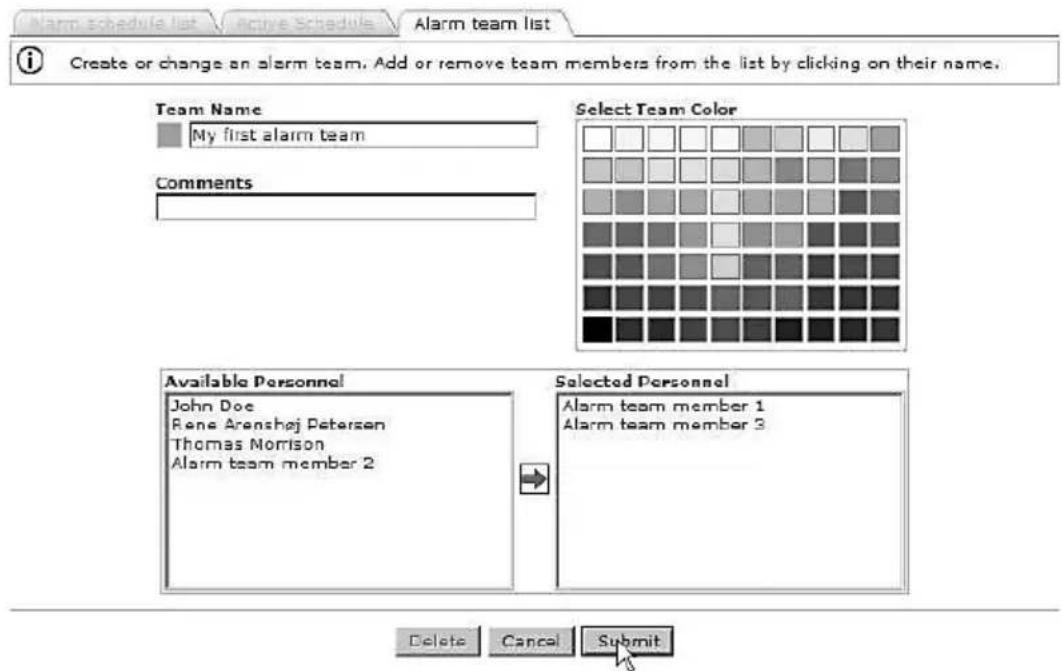
text_image
Alarm schedule list Active Schedule Alarm team list Create or change an alarm team. Add or remove team members from the list by clicking on their name. Team Name My first alarm team Comments Select Team Color Available Personnel John Doe Rene Arenshøj Petersen Thomas Morrison Alarm team member 2 Selected Personnel Alarm team member 1 Alarm team member 3 Delete Cancel SubmitTM04 7293 2410 TM04 7294 2410
Fig. 14 Alarm team
To assign a Week Schedule to a Section, right-click the Section name, and select the Week Schedule from the drop-down list.
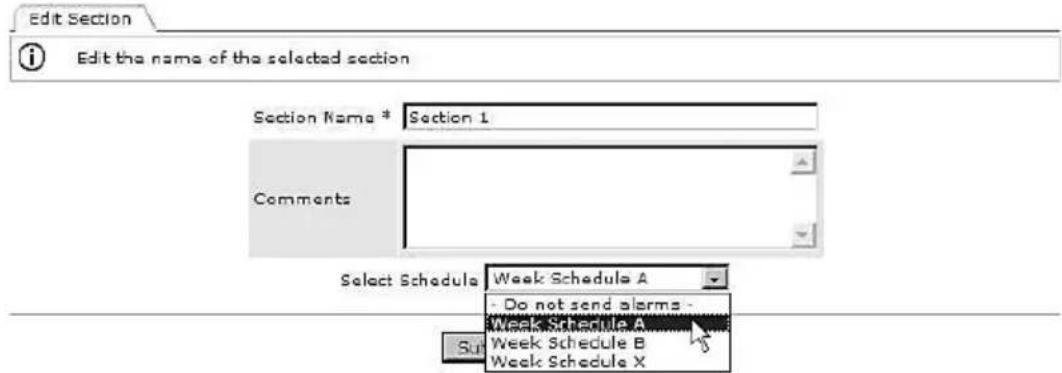
text_image
Edit Section Edit the name of the selected section Section Name * Section 1 Comments Select Schedule Week Schedule A Do not send alarms - Week Schedule A Week Schedule B Week Schedule XFig. 15 Assigning a Week Schedule
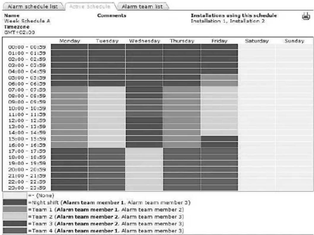
heatmap
| Timezone | Monday | Tuesday | Wednesday | Thursday | Friday | Saturday | Sunday | |---|---|---|---|---|---|---|---| | 00:00 - 00:59 | | | | | | | | | 01:00 - 01:59 | | | | | | | | | 02:00 - 02:59 | | | | | | | | | 03:00 - 03:59 | | | | | | | | | 04:00 - 04:59 | | | | | | | | | 05:00 - 05:59 | | | | | | | | | 06:00 - 06:59 | | | | | | | | | 07:00 - 07:59 | | | | | | | | | 08:00 - 08:59 | | | | | | | | | 09:00 - 09:59 | | | | | | | | | 10:00 - 10:59 | | | | | | | | | 11:00 - 11:59 | | | | | | | | | 12:00 - 12:59 | | | | | | | | | 13:00 - 13:59 | | | | | | | | | 14:00 - 14:59 | | | | | | | | | 15:00 - 15:59 | | | | | | | | | 16:00 - 16:59 | | | | | | | | | 17:00 - 17:59 | | | | | | | | | 18:00 - 18:59 | | | | | | | | | 19:00 - 19:59 | | | | | | | | | 20:00 - 20:59 | | | | | | | | | 21:00 - 21:59 | | | | | | | | | 22:00 - 22:59 | | | | | | | | | 23:00 - 23:59 | | | | | | | | | =-(None) =Night shift (Alarm team member 1, Alarm team member 3)=Team 1 (Alarm team member 1, Alarm team member 2)=Team 2 (Alarm team member 2, Alarm team member 3)=Team 3 (Alarm team member 2, Alarm team member 3)=Team 4 (Alarm team member 1, Alarm team member 3)TM04 7296 2410
Fig. 16 Example of Week Schedule
All GRM users are potential members of an alarm team. Users that have entered a mobile phone number on their Account details are able to receive alarms via SMS.
If there is no mobile phone number registered for a user, the e-mail address is the only way of delivering alarms.
Note
You can make as many Week Schedules as you like. They are not activated until you assign them to a Section.
Different Sections may operate on different Week Schedules.
10. Reports

text_image
Overview Schedule Reports Event Log Service AdminFig. 17 Reports
The system contains a report engine that will automatically generate summation reports. The contents of the reports depend on the application. The reports will typically run on a monthly basis and deliver an output which can be downloaded to a spreadsheet.
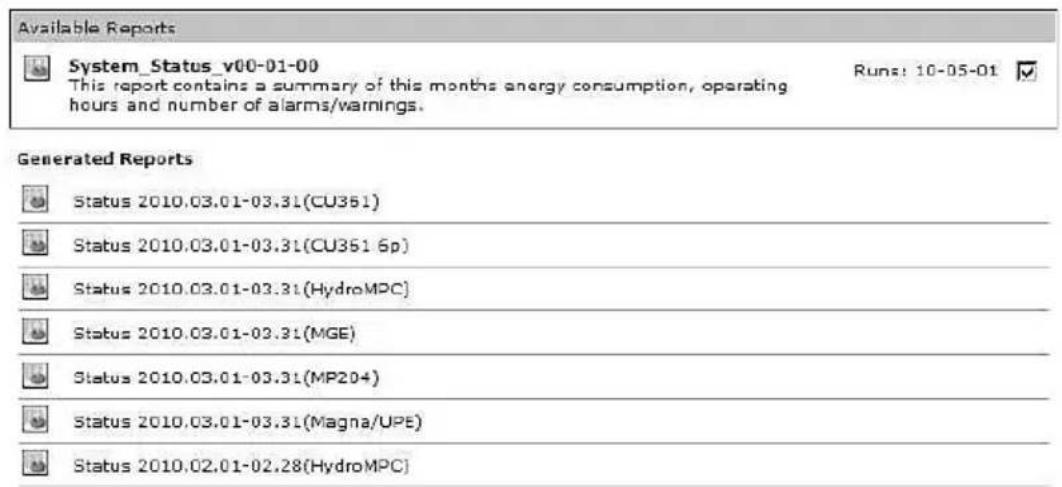
text_image
Available Reports System_Status_v00-01-00 This report contains a summary of this months energy consumption, operating hours and number of alarms/warnings. Runs: 10-05-01 Generated Reports Status 2010.03.01-03.31(CU351) Status 2010.03.01-03.31(CU351 6p) Status 2010.03.01-03.31(HydroMPC) Status 2010.03.01-03.31(MGE) Status 2010.03.01-03.31(MP204) Status 2010.03.01-03.31(Magna/UPE) Status 2010.02.01-02.28(HydroMPC)Fig. 18 Example of generated reports
11. Event log

text_image
Overview Schedule Reports Event Log Service AdminFig. 19 Event log
The Event log provides a full history of events and interactions related to each monitored device.
The Event log provides a record of the following:
- a l a r m s
- warnings
- cleared alarms and warnings
- user acknowledgement of alarms and warnings
- remote-control commands issued by a user
- service warnings
• comments entered manually by a user.
All events are time-stamped when they are received by the server, and user-initiated events are stamped with the user's system ID. The Event log can be downloaded to a spreadsheet.
| Date [+]ΔV | Event ΔV | Section | Installation | Unit |
| 2010-03-23 13:48:35 Cleared 2010-03-23 13:48:43 | Motor bearing temperature high (PT100), drive-end (DE) (Pump 2) | Waste Water Systems | DC PUST demo 1 | CU361 |
| 2010-03-22 23:31:25 Cleared 2010-03-23 09:23:20 | Communication fault, missing heartbeat | Waste Water Systems | DC PUST demo 1 | CU361 |
| 2010-03-22 15:28:42 User 05093 | Timedout waiting for connection, please try again and/or inspect GSM connection | Waste Water Systems | DC PUST demo 1 | CU361 |
| 2010-03-22 05:31:25 Cleared 2010-03-22 09:25:42 | Communication fault, missing heartbeat | Waste Water Systems | DC PUST demo 1 | CU361 |
| 2010-03-21 20:22:12 Cleared 2010-03-22 12:44:41 | Phase sequence reversal (Pump 1) | Waste Water Systems | DC PUST demo 1 | CU361 |
| 2010-03-21 20:22:12 Cleared 2010-03-22 12:44:41 | Phase sequence reversal (Pump 2) | Waste Water Systems | DC PUST demo 1 | CU361 |
Now showing 21-26 of 26 hits Previous page 3 of 3 Next
Fig. 20 Event log
12. Service

text_image
Overview Schedule Reports Event Log Service AdminFig. 21 Service
The Service tab provides a tool to manage service of pump installations. The basic functionality keeps track of the total number of operating hours for each of the pumps monitored by the system. For some products, the number of starts is also monitored.
You can set thresholds for each service parameter and be notified automatically via e-mail when a threshold is met. It is also possible to set a date on which you want to be notified if your service strategy is based on a time interval.
When a new pump is detected by the CIM 270, an entry for that pump is automatically created under the Service tab.
If you enter the product number of the monitored Grundfos pump, you will have direct online access to documentation, including service videos, pump curves, etc.
| Photo | Name | No. | Product Number | Notes | Next scheduled service |
| Pump 1 | 1 | 96566095 | Change shaft seal | 2012-11-12 | |
| Pump 1 | 1 | 96566095 | Change shaft seal | 2012-08-06 | |
| Pump 2 | 2 | 96566095 | Inspect | 2012-08-06 | |
| Pump 1 | 1 | 96566095 | Inspect | 2012-04-17 |
Fig. 22 Example of a Service log entry
13. Admin, user administration

text_image
Overview Schedule Reports Event Log Service AdminFig. 23 Admin
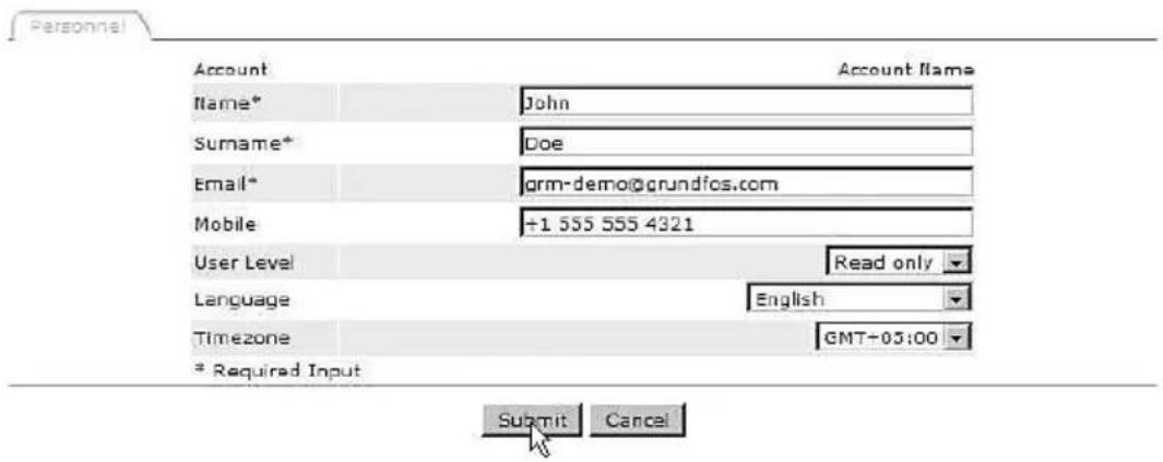
Under the Admin tab, you will find the functionality to create new users and to maintain the data of each registered user of the system.
To create a new user, fill in the following:
- name
- surname
• e-mail.
This is the minimum information required to create a new user in Grundfos Remote Management.
The field "Mobile" is optional. This number will be used to send SMS alarms to the user, if registered as an alarm recipient on a Schedule.
text_image
Account Name* John Surname* Doe Email* grm-demo@grundfos.com Mobile +1 555 555 4321 User Level Read only Language English Timezone GMT+03:00 * Required Input Submit CancelFig. 24 Creating a new user
Now select the appropriate user access level. Users can be assigned different access levels, depending on their intended use of the system.
There are three different access levels:
- full access
- operator access
- read-only access.
Full access
A full-access user has access to all features of the system, for example to view the following:
- current status of the system
- trend curves
- reports
- event log
- service log.
A full-access user can operate the system via remote access, i.e.
- reset the system
• perform remote start/stop
- change settings
- manage administration rights.
A full-access user can create, change or delete a Section, an Installation, a user Account, etc.
We recommend you only to have one or two full-access users.
Operator access
An operator is able to remote-control installations, for example perform the following:
- remote resetting
- remote start/stop of a pump
- change of setpoint for system pressure.
Operators are users that you would normally also trust with physical access to the monitored systems.
Read-only access
Read-only users can view the following:
- current status of the system
- trend curves
- reports
- event log
- service log.
This group of users cannot change settings and affect the operation of an installation.
Read-only users would normally access the system in order to analyse the performance. Users who are intended to receive SMS alarms only, not to access the system, should be created as read-only users.
Language
Select the user's preferred language from the list of available languages.
Time zone
Enter the time zone in which an alarm schedule is used. This feature of the system makes it easy to work with alarm teams in different time zones.
Observe the following:
- Place Installations in the same time zone in the same folder.
- Set the right time zone for the alarm schedule you assign to the Section.
If you do not operate with service teams across different time zones, just use the default setting.
14. Alarms
By default the CIM 270 will transmit alarms generated by a monitored GENIbus device to the central server. There are, however, also some other alarms available.
14.1 Heartbeat
The alarm text "Communication fault, missing heartbeat" is a server-generated alarm message that informs you that a CIM 270 has failed to routinely contact the central server.
Recommended actions to take when this alarm is received:
-
Log on to the GRM, and attempt to connect to the Installation.
-
Check the status of the GPRS network in the area together with your telecommunication provider.
-
Check the power supply to the installation.
14.2 Power supply failure, operating on battery
If the CIM 270 has a backup battery fitted, it is able to report when it switches to battery operation.
Once the CIM 270 is running on battery, it will stop sampling data and report a fault to the server.
Once the power is restored, the CIM 270 will resume normal monitoring operation, and you will be notified that the power has returned.
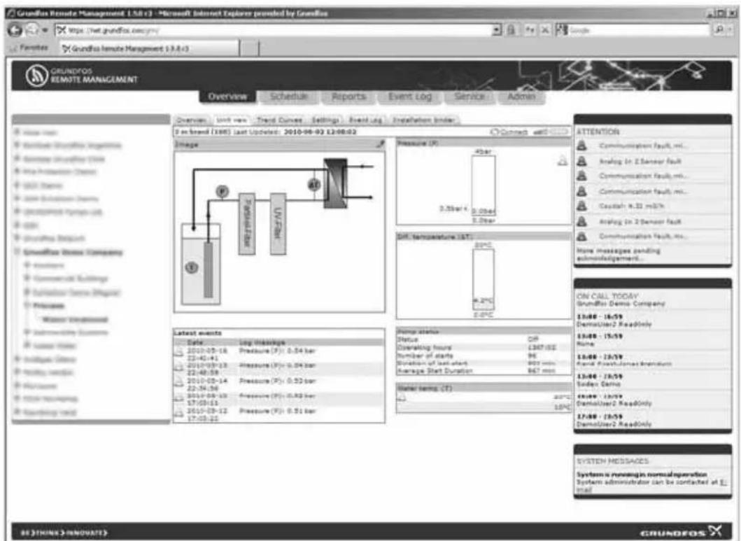
15. Multi-purpose IO module
The multi-purpose IO module in the CIU 27X is designed especially for use in Grundfos Remote Management. Pumps without GENIbus connection are connected and monitored via the IO module. When a digital input is specified to monitor a pump during configuration of the IO module, a pump log will be created under the Service tab.
The IO module enables you to monitor sensors, meters, standard pumps, etc. and to remote-control a relay and an analog output (0-10 V) from your internet browser.
text_image
Grundfos Remote Management 1.5.8 (1) - Microsoft Internet Explorer provided by Grundfos Grundfos Remote Management 13.8.4 (3) Overview Schedule Reports Event Log Service Admin Overview Unit new Trend Curves Settings Front Log Installation border 3 in brand (1988) Last Updated: 2010-06-02 12:08:02 Image Pressure (P): 40bar 2.5bar / 4 0.0bar 2.5bar Diff. temperature (ST): 80°C 4.2°C 0.0°C Latest events Date: Log Message 2010-05-18 Pressure (F): 0.04 bar 22:40:45 2010-05-13 Pressure (F): 0.04 bar 22:48:58 2010-05-14 Pressure (F): 0.02 bar 22:56:56 2010-05-13 Pressure (F): 0.02 bar 17:03:15 2010-05-12 Pressure (F): 0.01 bar 17:03:25 Temp status Off Status QIP Operating hours 1367.05 Number of starts 96 Duration of last start 903 min Average Start Duration 867 min Water time (T): 2010/12/25 10PM ATTENTION Communication fault, mI... Analog in 2 Sensor fault Communication fault, mI... Creatish R-32 mS/N Analog in 2 Sensor fault Communication fault, mI... Main messages pending adminislatgement... ON CALL TODAY Grundfos Demo Company 13:48 - 16:59 DemoUser2 ReadOnly 13:48 - 15:59 None 13:48 - 13:59 Ronal Process/James Breakdown 13:48 - 13:59 Soder Carbo 13:48 - 13:59 DemoUser2 ReadOnly 17:48 - 18:59 DemoUser2 ReadOnly SYSTEM MESSAGES System is moving in normal operation System administrator can be contacted at 1: mail BE ?THINK ?INNOUATE? GRUNDEOSFig. 25 Example of graphical display of monitored sensors
The IO module has two configurable inputs (analog/digital) set by use of jumpers.
The configurable inputs can be set as the following:
- digital signal
- analog signal (0-10 V)
• analog signal (4-20 mA)
• analog signal (0-20 mA).
The IO module has one Pt100/Pt1000 sensor input and one analog output.
For further information about the IO module, see installation and operating instructions for Multi-purpose IO module in CIU 27X.
Once you are online with your application, you can perform the following actions:
- Set up names for all input types.
- Scale information for the analog inputs.
- Set alarm thresholds for analog inputs.
- Define digital inputs for alarm detection.
- Define digital inputs to count pulse signals.
- Define digital inputs to monitor operations, i.e. log operating hours and number of starts of a connected pump.
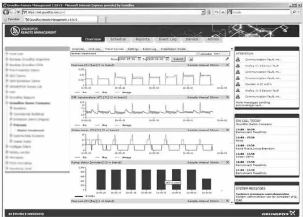
On the basis of the above definitions, a graphical user interface is generated complete with the option of seeing trend data for the monitored I/O devices.
text_image
Grundfos Remote Management 1.58 (1) - Microsoft Internet Explorer provided by Grundfos http://net.grundfos.com/yr/ Features Grundfos Remote Management 13.3.0 (1) Overview Schedule Reports Event Log Service Admin Overview Unit view Trend Curves Settings Event Log Installation border Water treatment From 2019-05-26 To 2020-04-02 Submit Pressure (P): [bar] (3 m brand) Sample interval 30mm Diff. temperature (dT) [°C] (3 m brand) Sample interval 30mm Water temp. (V) (°C) (3 m brand) Sample interval 30mm Fump status [minutes] (3 m brand) Sample interval 30mm Pressure (P): [bar] (4 m brand) Sample interval 30mm ATTENTION Communication fault, ms... Analog In 2 Sensor fault Communication fault, ms... Communication fault, ms... Crustal + 22 mS/s Analog In 2 Sensor fault Show Messages pending system management... ON CALL TODAY Grundfos Demo Company 13:46 - 16:59 DemusUser2 ReadOnly 13:46 - 15:59 None 13:46 - 17:59 Rand Rose/Jones Expendum 13:46 - 17:59 Index Data 16:46 - 17:59 DemusUser2 ReadOnly 17:46 - 18:59 DemusUser2 ReadOnly SYSTEM MESSAGES System is maintaining normal conversion System administrator can be contacted at E-mail BE THINK INNOVAES GRUNDOSFig. 26 Example of graphical display of data from monitored sensors
GENIbus I/O modules are available from Grundfos if you should need additional I/O functionality.
16. GSM LED of the CIM 270 (left)
LED status Location Description
| No GSM network.Yellow LED: . ✉ . ✉ (1-second intervals) | [H GYZ] | • No SIM card in the CIM 270.• The PIN code of the SIM card is not known by the CIM 270.• No GSM coverage. |
| Connection to GSM network established.Yellow LED: ... ✉ ✉ ✉ ... (3-second intervals) | [K YGG] | The CIM 270 has successfully connected to the GSM network.Normal operation. |
| Sending or receiving an SMS.Permanently green LED. |  | This will typically be observed during the initial configuration of the CIM 270. |
| GPRS connection to central GRM server established.Green LED: ... ✉ ✉ ✉ ... (3-second intervals) | 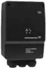 | This can be observed when connecting to an installation. |
17. GENIbus LED of the CIM 270 (right)
LED status Location Description
| CIM 270 (factory default). Permanently red LED. | 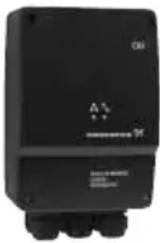 | ·The CIM 270 has not been connected to any GENIbus device yet. |
| The CIM 270 has loaded a GENIbus device, but there is a problem on the GENIbus network. Red LED: . * - * * (1-second intervals) | 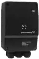 | ·A GENIbus device expected by the CIM 270 has been removed, switched off or its address has been changed. ·There is a cable or connector problem on the GENIbus network. ·The device detected is not supported by the CIM 270. |
| The GENIbus network is configured correctly. Permanently green LED. | 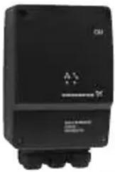 | GENIbus status OK. |
18. Fault finding
| Fault | Possible | cause | Remedy |
| 1. No response from the CIM 270. | a) The CIM 270 is not connected to the GSM network. | Check the GSM LED of the CIM 270. See section 5.1 Preparing the SIM card. | |
| b) You have not entered a correct combination of mobile phone number and IMEI number. | Check the phone and IMEI numbers. | ||
| c) The SMS communication between the central server and the CIM 270 is delayed by the network operator. | Wait a few minutes and retry. You may experience a delay in the SMS service. | ||

During initial setup of a new CIM 270, the PIN code of the SIM card must be set to 4321. To avoid unwarranted use of the SIM card in case of theft, we recommend you to set a new PIN code for the SIM card during the configuration procedure.
Argentina
Bombas GRUNDFOS de Argentina S.A.
Ruta Panamericana km. 37.500 Lote 34A
1619 - Garin
GRUNDFOS Pumps Pty. Ltd
P.O. Box 2040
Regency Park
South Australia 5942
Phone: +61-8-8461-4611
Telefax: +61-8-8340 0155
Austria
Iztochna Tangenta street no. 100
BG - 1592 Sofia
Tel. +359 2 49 22 200
Fax. +359 2 49 22 201
email: bulgaria@grundfos.bg
Canada
GRUNDFOS Canada Inc.
2941 Brighton Road
Oakville, Ontario
L6H 6C9
Phone: +1-905 829 9533
Telefax: +1-905 829 9512
China
GRUNDFOS Pumps (Shanghai) Co. Ltd.
50/F Maxdo Center No. 8 XingYi Rd.
Hongqiao development Zone
Shanghai 200336
PRC
Phone: +86-021-612 252 22
Telefax: +86-021-612 253 33
Croatia
GRUNDFOS CROATIA d.o.o.
Cebini 37, Buzin
HR-10010 Zagreb
Phone: +385 1 6595 400
Telefax: +385 1 6595 499
www.grundfos.hr
Czech Republic
GRUNDFOS s.r.o.
Čajkovského 21
779 00 Olomouc
Phone: +420-585-716 111
Telefax: +420-585-716 299
Denmark
GRUNDFOS DK A/S
Martin Bachs Vej 3
DK-8850 Bjerringbro
Tlf.: +45-87 50 50 50
Telefax: +45-87 50 51 51
E-mail: info_GDK@grundfos.com
www.grundfos.com/DK
Estonia
Unit 1, Ground floor
Siu Wai Industrial Centre
29-33 Wing Hong Street &
68 King Lam Street, Cheung Sha Wan
Kowloon
Phone: +852-27861706 / 27861741
Telefax: +852-27858664
Hungary
GRUNDFOS Pumps India Private Lim-
ited
118 Old Mahabalipuram Road
Thoraipakkam
Chennai 600 096
Phone: +91-44 2496 6800
Indonesia
PT GRUNDFOS Pompa
Jl. Rawa Sumur III, Blok III / CC-1
Kawasan Industri, Pulogadung
Jakarta 13930
Phone: +62-21-460 6909
Telefax: +62-21-460 6910 / 460 6901
Ireland
GRUNDFOS (Ireland) Ltd.
Unit A, Merrywell Business Park
Ballymount Road Lower
Dublin 12
Phone: +353-1-4089 800
Telefax: +353-1-4089 830
Italy
GRUNDFOS Pompe Italia S.r.l.
Via Gran Sasso 4
6th Floor, Aju Building 679-5
Yeoksam-dong, Kangnam-ku, 135-916
Seoul, Korea
Phone: +82-2-5317 600
Telefax: +82-2-5633 725
Latvia
SIA GRUNDFOS Pumps Latvia
Deglava biznesa centrs
7 Jalan Peguam U1/25
Glenmarie Industrial Park
40150 Shah Alam
Selangor
Phone: +60-3-5569 2922
Telefax: +60-3-5569 2866
México
Boulevard TLC No. 15
GRUNDFOS Netherlands
Veluwezoom 35
1326 AE Almere
Postbus 22015
1302 CA ALMERE
Tel.: +31-88-478 6336
Telefax: +31-88-478 6332
e-mail: info_gnl@grundfos.com
New Zealand
GRUNDFOS Pumps NZ Ltd.
17 Beatrice Tinsley Crescent
North Harbour Industrial Estate
Albany, Auckland
Phone: +64-9-415 3240
Telefax: +64-9-415 3250
Norway
GRUNDFOS Pumper A/S
Strømsveien 344
Postboks 235, Leirdal
N-1011 Oslo
Tlf.: +47-22 90 47 00
Telefax: +47-22 32 21 50
Poland
GRUNDFOS Pompy Sp. z o.o.
ul. Klonowa 23
Corner Mountjoy and George Allen
Roads
Wilbart Ext. 2
Bedfordview 2008
Phone: (+27) 11 579 4800
Fax: (+27) 11 455 6066
E-mail: lsmart@grundfos.com
Spain
The name Grundfos, the Grundfos logo, and the payoff Be–Think–Innovate are registered trademarks owned by Grundfos Management A/S or Grundfos A/S, Denmark. All rights reserved worldwide.