CU 362 - Pump Grundfos - Free user manual and instructions
Find the device manual for free CU 362 Grundfos in PDF.

| Brand | Grundfos |
| Model | CU 362 (GRUNDFOS iSOLUTIONS MONITOR CIU) |
| Category | Pump monitoring and communication interface |
| Type | Communication interface (GiM CIU) |
| Power supply | 24-240 VAC/VDC ±10%, 50/60 Hz, max. 11 W |
| Protection rating | IP54 (IEC 60529), Type 2 (UL 50) - indoor use only |
| Ambient temperature (operation) | -20 to +45 °C |
| Ambient temperature (storage/transport) | -20 to +60 °C |
| Relative humidity | 95% non-condensing |
| Maximum altitude | 2000 m |
| Pollution degree | Category 3 |
| Communication | GENIbus (master/slave), Modbus RTU, Bluetooth (Grundfos GO Remote 2.0) |
| Inputs/Outputs | 2 x analog/digital inputs, 1 x Pt100/1000 input, 1 x digital output (30 V/500 mA) |
| Main functions | CR pump monitoring (dry running, temperature, vibration, cavitation), interface between pump and network, diagnosis and predictive maintenance |
| Mounting | Wall-mounted, cable glands downwards, 4 screws (torque 1.25 Nm) |
| Maintenance and cleaning | Clean with a dry cloth only |
| Safety | Not designed for personal safety; installation by qualified personnel; follow disconnection and grounding instructions |
| Disposal | Do not dispose with household waste; take to a collection point or contact Grundfos |
| Repairability | Non-repairable module, must be replaced |
Frequently Asked Questions - CU 362 Grundfos
User questions about CU 362 Grundfos
0 question about this device. Answer the ones you know or ask your own.
Ask a new question about this device
Download the instructions for your Pump in PDF format for free! Find your manual CU 362 - Grundfos and take your electronic device back in hand. On this page are published all the documents necessary for the use of your device. CU 362 by Grundfos.
USER MANUAL CU 362 Grundfos
Installation and operating instructions


GiM CIU
Installation and operating instructions
Other languages
http://net.grundfos.com/qr/i/99802941
be
think
innovate
GRUNDFOS

GiM CIU
English (GB)
Installation and operating instructions 4
Deutsch (DE)
FCC/ISED general requirements. 160
Original installation and operating instructions
Table of contents
- General information ..... 4
1.1 Hazard statements ..... 4
1.2 Notes 4
- Product introduction ..... 5
2.1 Product description ..... 5
2.2 Intended use 5
2.3 Applications 5
2.4 LEDs 5
2.5 Identification. 6
- Receiving the product. 6
3.1 Inspecting the product ..... 6
3.2 Scope of delivery 6
- Installation requirements ..... 6
4.1 Location 6
4.2 Radio frequency radiation exposure, for Canada and US only . . . . . . . . . . . 6
- Mechanical installation ..... 7
5.1 Mounting on the wall 7 -
Electrical connection ..... 8
6.1 Terminals 9
6.2 Connecting the power supply. 9
6.3 Connecting GENIbus to the pump ..... 1 0
6.4 Sensor cable 1 1
6.5 Connecting the IO connections.....12
6.6 Connecting to a Modbus network ..... 1 3 -
Starting up the product ..... 1 3
7.1 Connecting the unit to Grundfos GO Remote 2.0....13
8. Servicing the product ..... 1 4
8.1 Cleaning the product ..... 1 4
9. Technical data ..... 1 4
10. Disposing of the product ..... 1 5
1. General information

Read this document before you install the product. Installation and operation must comply with local regulations and accepted codes of good practice.
Read the installation and operating instructions for the relevant CIM module.
1.1 Hazard statements
The symbols and hazard statements below may appear in Grundfos installation and operating instructions, safety instructions and service instructions.
DANGER
Indicates a hazardous situation which, if not avoided, will result in death or serious personal injury.
WARNING
Indicates a hazardous situation which, if not avoided, could result in death or serious personal injury.

CAUTION
Indicates a hazardous situation which, if not avoided, could result in minor or moderate personal injury.
The hazard statements are structured in the following way:
SIGNAL WORD
Description of the hazard
Consequence of ignoring the warning • Action to avoid the hazard.
1.2 Notes
The symbols and notes below may appear in Grundfos installation and operating instructions, safety instructions and service instructions.

Observe these instructions for explosion-proof products.

A blue or grey circle with a white graphical symbol indicates that an action must be taken.

A red or grey circle with a diagonal bar, possibly with a black graphical symbol, indicates that an action must not be taken or must be stopped.

If these instructions are not observed, it may result in malfunction or damage to the equipment.

Tips and advice that make the work easier.
2. Product introduction
2.1 Product description
The product monitors the activity of a Grundfos CR pump. It detects possible irregularities concerning CR pumps to increase system uptime and keep service and maintenance people on track with pump operation and status for maintenance planning. GRUNDFOS iSOLUTIONS MONITOR is referred to as "GiM CIU" in this document.
2.2 Intended use
The product is intended for use with a Grundfos CR pump. It can be used for monitoring and protection of the pump.

WARNING
Personal injury
Death or serious personal injury
- This product is not designed for ensuring safety of persons.
2.3 Applications
The product is used as a communication interface between a Grundfos product and a main network. It is used together with a CIM module (CIM = Communication Interface Module) fitted in the unit. GENIbus is optional communication between the unit and a Grundfos product.
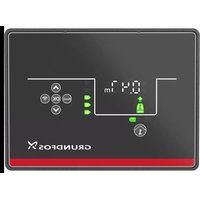
2.4 LEDs
The three LEDs are placed on the front cover of the GiM CIU. The Bluetooth button is placed on the bottom on one of the cable glands.
Explanation of the symbols
| Symbol Description | |
 | Red and green status LED for the main network. See the installation and operating instructions for the CIM module for more information. |
 | Status LED for the internal communication between the CIM module and the Grundfos product. See the installation and operating instructions for the CIM module for more information. |
| STATUS | Monitor status.See the following table for descriptions. |
 | Bluetooth button for pairing between GiM CIU and Grundfos GO Remote 2.0. |
STATUS LED Description
| Permanently green The system is working. | |
| Flashing green | GiM CIU is in learning mode. |
| Permanently yellow | A warning from the CR pump, for example, high media temperature, vibration or cavitation. It could also be a warning indicating, for example, a VTU sensor fault or missing power for the real-time clock. |
| Permanently red | An alarm from the CR pump, for example, dry run, high media temperature, vibration or cavitation. |
2.5 Identification
2.5.1 Nameplate
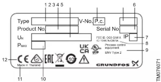
Example of a nameplate
| Pos. Description |
| 1 Type designation |
| 2 Product number |
| 3 Supply voltage |
| 4 Version number |
| 5 Production code (year and week) |
| 6 Serial number |
| 7 Enclosure class |
| 8 FCC and IC text, only for UL variants |
| 9 Environmental type |
| 10 Rated power |
| 11 Production site |
| 12 Markings and approvals |
Related information
4.1 Location
3. Receiving the product
3.1 Inspecting the product
Before installing the product, do the following:
- Check that the product is as ordered.
- Check that no visible parts have been damaged.
- If parts are damaged or missing, contact your local Grundfos sales company.
3.2 Scope of delivery
The packaging contains the following items:
- GRUNDFOS iSOLUTIONS MONITOR CIU unit (GiM CIU)
- installation and operating instructions for the product.
4. Installation requirements
4.1 Location
Install the product in a location that meets the following requirements:
- Place the product in a flood-safe place.
- Make sure that the ambient temperature is within the limits.
• Install the product as close as possible to the connected pumps, sensors, and accessories.
- The product must be easily accessible.
- You must install the product in a protective shed or enclosure to avoid direct sunlight and rain.
- Indoor installation: The product must be installed in a well-ventilated room to ensure cooling of its components.
Related information
2.5.1 Nameplate
9. Technical data
4.2 Radio frequency radiation exposure, for Canada and US only
This equipment complies with FCC and ISED radiation exposure limits set forth for an uncontrolled environment. This equipment must be installed and operated with a minimum distance of 20 cm (0.66 feet) between the radiator and your body.
FCC ID: OG3-GIM1A
IC: 10447A-GIM1A
5. Mechanical installation
5.1 Mounting on the wall
Mount the unit on a surface. The cable glands must face downwards.

CAUTION
The product can fall down
Minor or moderate personal injury
- Make sure to use screws that fit into the unit and support its weight.
-
All cable screens must be connected to earth. If it is not possible to use cable clamps, the stripped part of the cable screen must be as short as possible to reduce the impedance at high frequencies.
• The cable glands must face downwards. -
Loosen the screws and remove the front cover.
- Drill holes in the surface.
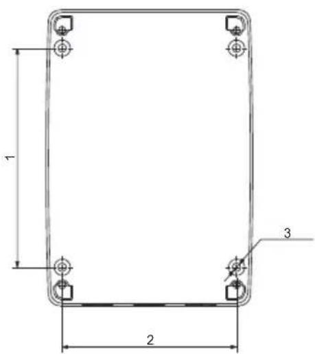
TM076032
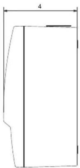
| Pos. Dimensions [mm] (inch) |
| 1 115 (4.53") |
| 2 91 (3.58") |
| 3 ø4.5 (0.18") |
| 4 81.5 (3.21") |
- Insert wall plugs, if applicable.
- Fit the four screws in the mounting holes and cross-tighten the screws, 1.25 Nm.
6. Electrical connection
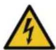
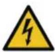
DANGER
Electric shock
Death or serious personal injury
- Applies to supply voltages above 30 V_RMS / 60 VDC: The installation must incorporate a switch or a circuit breaker in order to switch off the mains supply. It must be close to the CIU unit and easily accessible for the operator. It must be marked as a disconnecting device for the CIU unit.
- In case of an insulation fault, the fault current may be a pulsating DC. Observe national legislation about requirements for and selection of a Residual Current Device (RCD) when installing the pump.
The residual-current circuit breaker must be marked like this:

TM072868
WARNING
Electric shock
Death or serious personal injury
- Switch off the power supply before making any electrical connections. Make sure that the power supply cannot be switched on accidentally.
- The protective earth from the socket outlet must be connected to the protective earth in the pump. Therefore, the applied plug must have the same protective earth connection systems as the socket outlet, or a suitable adapter must be applied.
- Ensure that the high-voltage protection cover is mounted correctly once the installation is finished.
- Tighten the cable glands securely to avoid water coming into the unit or the cables being pulled out.
- The CIU unit and GENIbus must only be connected to SELV or SELV-E circuits.
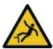
WARNING
Falling off ladder
Death or serious personal injury
- Take care when installing the unit on the pump.
CAUTION
Hot surface
Minor or moderate personal injury
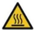
- Do not touch the pump. The surface may be hot.

All installation work must only be carried out by qualified and authorised persons.
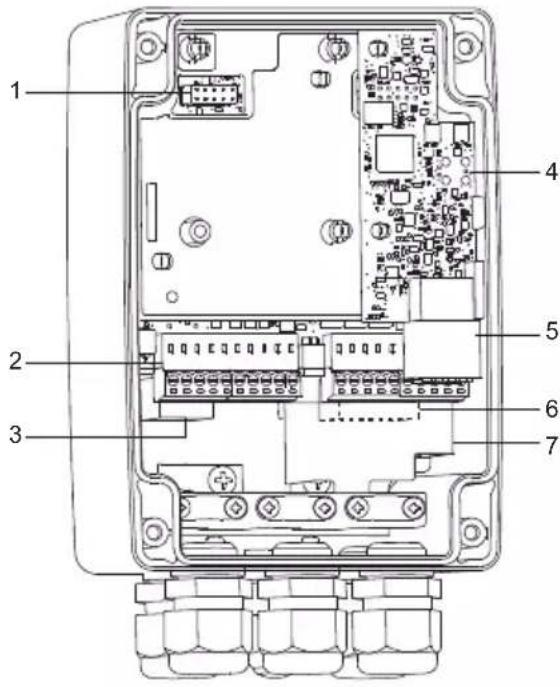
TM076522
Pos. Description
| 1 CIM connection |
| 2 IO connections |
| 3 GENIbus master, connection to the pump |
| 4 VTU board |
| 5 Sensor connections |
| 6 Power supply |
| 7 High-voltage protection cover |
Related information
6.2 Connecting the power supply
6.3 Connecting GENIbus to the pump
6.4.1 Mounting the sensor cable
6.5 Connecting the IO connections

6.1 Terminals

Remember to tighten the cable glands before you switch on the power.
The tightening torque is 1.5 Nm.
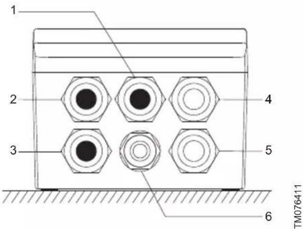
Pos. Description
| 1 | Blank (default)Options: antenna, Ethernet or IO |
| 2 | Blank (default)Options: antenna, Ethernet or IO |
| 3 | Blank (default)Options: GENIbus master (pump) or IO |
| 4 VTU sensor | |
| 5 Power supply | |
| 6 Bluetooth connect button | |
6.2 Connecting the power supply
WARNING
Electric shock
Death or serious personal injury
- Make sure there is proper insulation around the supply cable.
-
The protective earth wire must be longer than the neutral and phase wires.
-
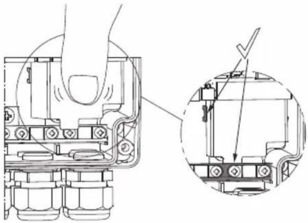
Remove the front cover.
- Remove the sensor connector and the IO connections.
- Pull the high-voltage protection cover upwards to access the connectors.
- Lead the supply cable through the cable gland.
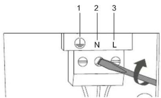
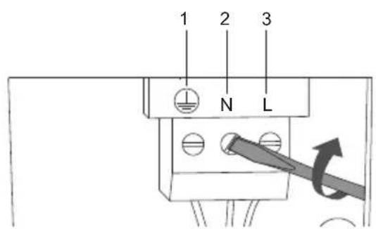
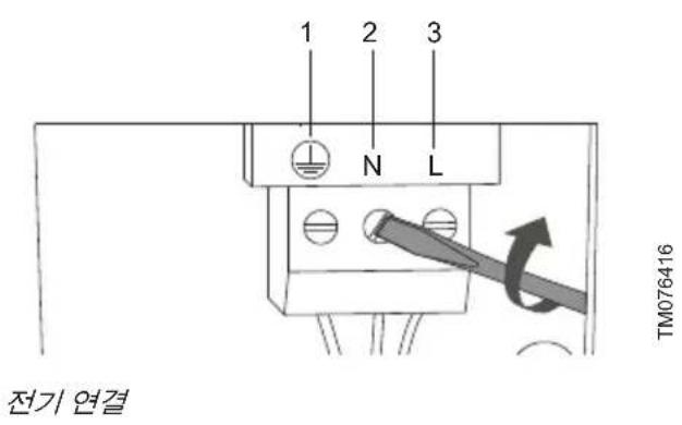
- Connect the supply conductors to earth, N and L.
- Tighten the cable glands.
- Fit the high-voltage protection cover again.
natural_image
Technical line drawing of a mechanical assembly with no visible text or symbolsTM077422TM077423
natural_image
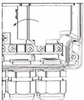
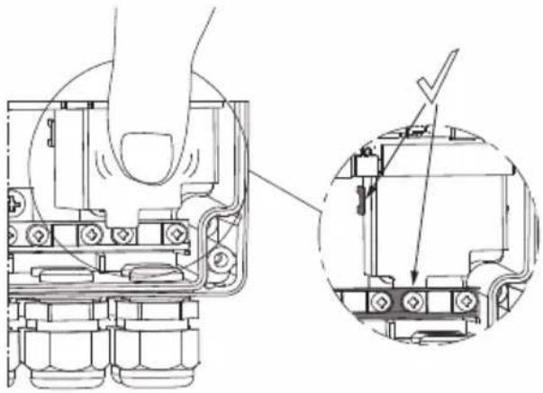
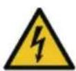
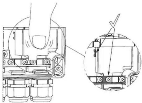
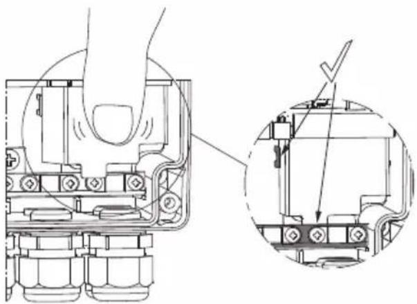
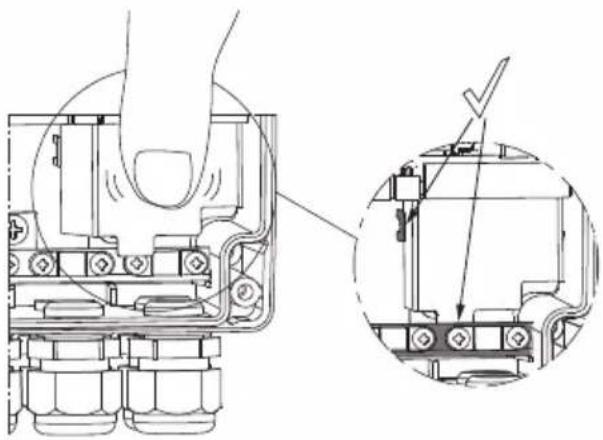
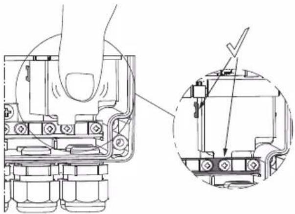
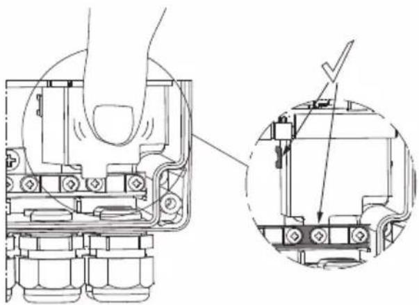
Technical line drawing of a mechanical assembly with a magnified inset showing internal components (no text or symbols)Push the cover down firmly
- Fit the front cover.
Example:

TM076416
Electrical connection
| Pos. Description |
| 1 Protective earth terminal |
| 2 Neutral terminal |
| 3 Phase terminal |
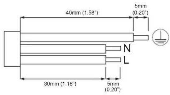
TM077743
Wire requirements
Related information
- Electrical connection
6.3 Connecting GENIbus to the pump
6.5 Connecting the IO connections
6.3 Connecting GENIbus to the pump
- Remove the front cover.
- Lead the GENIbus cable through the cable gland.
- Connect the conductors to terminals A, Y and B.
- Connect the cable screen under the earth clamp, and tighten the earth clamp.
- Tighten the cable gland.
- Fit the front cover.
Example:
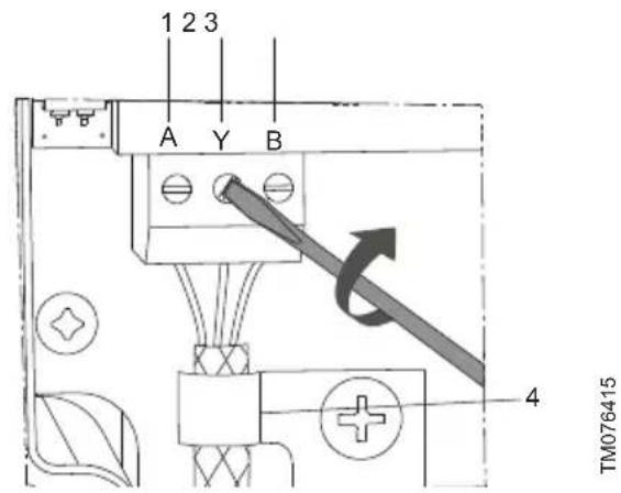
GENIbus connection
| Pos. Designation Description | ||
| 1 | A | GENIbus terminal A. Positive data signal. |
| 2 Y GENIbus terminal Y | ||
| 3 | B | GENIbus terminal B.Negative data signal. |
| 4 - Earth clamp | ||
Related information
- Electrical connection
6.2 Connecting the power supply
6.4 Sensor cable
WARNING
Fall hazard
Death or serious personal injury
- Follow local working environment regulations.
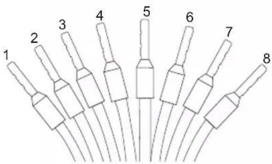
6.4.1 Mounting the sensor cable
- Read the GiM quick guide to see how to mount the sensor cable.

OR99802939
net.grundfos.com/qr/i/99802939
TMO76437
Pos. Colour Designation Description
| 1 White DR Dry run | ||
| 2 Brown V+ Supply | ||
| 3 Green GND Ground | ||
| 4 Yellow Rw1 | Pt100 | |
| 5 Grey | Rw2 | Pt100 |
| 6 Pink | Vin Analog | |
| 7 Blue | GND Ground | |
| 8 Red | GND Ground | |
For more information on the VTU sensor, see the data sheet.

OR99873130
net.grundfos.com/qr/i/99873130
Related information
- Electrical connection
6.5 Connecting the IO connections
WARNING
Electric shock
Death or serious personal injury
- The IO connections of the GiM CIU unit must be connected to SELV or SELV-E circuits only.

A screened cable must be used and it must be connected to an earth clamp inside the unit.
- Connect the input and output terminals according to the drawing.
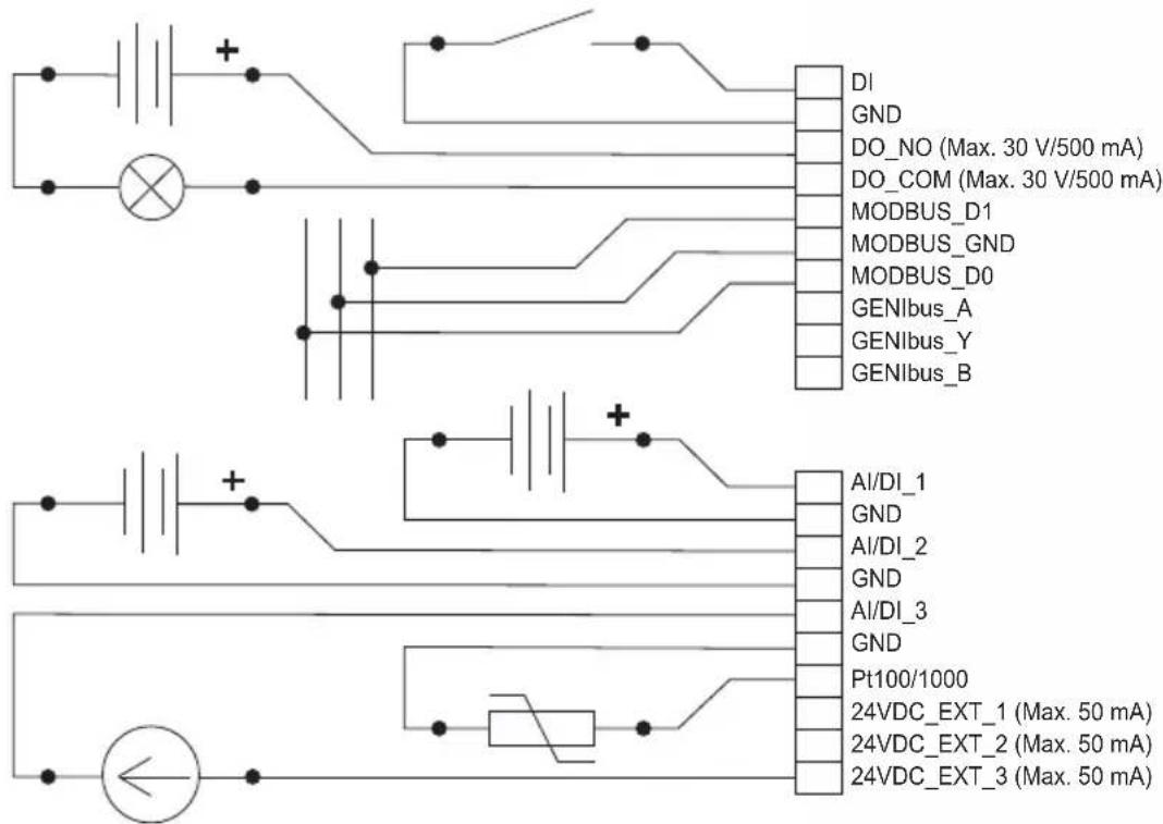
TM076438
Wiring diagram
Options for configuration of connections
| Electrical signals DI AI/DI 1 AI/DI 2 AI/DI 3 Pt100(0) |
| Digital input x |
| Analog input, 0 - 20 mA x x x |
| Analog input, 4 - 20 mA x x x |
| Analog input, 0 - 10 V x x x |
| Analog input, 0 - 5 V x x x |
| Analog input, 0.5 - 3.5 V x x x |
| Pt100 x |
| Pt1000 x |
Related information
- Electrical connection
6.2 Connecting the power supply
6.6 Connecting to a Modbus network
6.6 Connecting to a Modbus network

A screened, twisted-pair cable must be used. The cable screen must be connected to protective earth at both ends. It is important to connect the screen to earth through the earth clamp and to connect the screen to earth in all units connected to the bus line.
Recommended connection
| Modbus terminal | Colour Data signal |
| D1 Yellow Positive | |
| D0 Brown Negative | |
| Common/GND Grey Common/GND | |
- Connect the yellow conductor(s) to terminal D1.
- Connect the brown conductor(s) to terminal D0.
- Connect the grey conductor(s) to terminal Common/GND.
- Connect the cable screens to earth via the earth clamp.
Related information
6.5 Connecting the IO connections
7. Starting up the product
7.1 Connecting the unit to Grundfos GO Remote 2.0
Before connecting the product, the Grundfos GO Remote 2.0 app must be downloaded to your smartphone or tablet. The app is free of charge and available for iOS and Android devices.
CAUTION
Radiation
Minor or moderate personal injury
- Human tissue may be heated by RF energy. Locate the antenna at a minimum distance of 20 cm (7.87 inches) from any body parts.
- Open Grundfos GO Remote 2.0 on your device. Make sure that Bluetooth is enabled.
Your device must be within reach of the product to establish Bluetooth connection. -
Press the connect icon in Grundfos GO Remote 2.0.
-
Press the connect button on the product. The blue LED is flashing until your device is connected. Once the connection is established, the LED is permanently on.
Grundfos GO Remote 2.0 is now loading the data for the product.
- Refer to the GiM quick guide for further information regarding startup.

QR99802939
net.grundfos.com/qr/i/99802939
8. Servicing the product
The product cannot be serviced.
- Contact Grundfos. If the product is faulty, it must be replaced.
8.1 Cleaning the product
The product must only be cleaned with a clean dry or a soapy damp cloth.
9. Technical data
Electrical supply
| Transient overvoltage Category II | |
| Supply voltage | 24-240 VAC/VDC, ± 10 % |
| Frequency DC, 50/60 Hz | |
| Max. power consumption 11 W | |
Cables
| Power supply cable | IEC: 0.75 - 4 mm ^2 UL: 18 - 12 AWGUse a 3-core cable that meets the requirements of the National Electric Code. |
| Use copper or copper-clad aluminum conductors only.Use a power cable with an outer diameter of 6 - 10 mm only. | |
| Recommended communication cable | Screened, double twisted-pairCross-section: 0.2 - 0.3 mm ^2 AWG: 24 - 22Maximum cable length: 1200 m (4000 ft)Use a communication cable with an outer diameter of 4 - 10 mm. |
| Cable entry | 5 x M16 3.5 - 10 mm clamping range |
Fuses
| Back-up fuse | Maximum 10 A. Both standard fuses as well as quick- and slow-blow fuses are suitable. |
| Short-circuit protection | Use fuses that comply with IEC 60127. USA and Canada (branch circuit protection): Use a UL/CSA listed non-time delay (high capacity) fuse that complies with the UL248 series or an inverse time circuit breaker that complies with UL489. Fuse types RK1, RK5, J, and CC are acceptable. |
GENIbus master, for pump connection
| Transceiver RS-485 |
| Protocol GENIbus |
| Parity None |
| Stop bits 1 |
| Transmission speed 9600 bit/s |
GENIbus connection, for Grundfos GO Remote PC
| Transceiver | RS-485 |
| Protocol GENIbus | |
| Parity None | |
| Stop bits 1 | |
| Transmission speed | 9600 (default), 19200, 38400, 115200 bit/s |
Modbus RTU
| Transceiver | RS-485 |
| Protocol Modbus | |
| Parity None, odd, even (default) | |
| Stop bits 1 (default), 2 | |
| Modbus address 1-247. Default: 247. | |
| Transmission speed | 9600 (default), 19200, 38400, 115200 bit/s |
Environmental conditions
| Max. altitude above sea level | 2000 m (6562 ft) |
| Relative humidity 95 %, non-condensing | |
| Pollution degree Category 3 | |
| Enclosure class | IP54 according to IEC 60529Type 2 according to UL 50For indoor use only. |
Ambient temperature
| During operation | -20 to +45 °C(-4 to +113 °F) |
| During storage | -20 to +60 °C(-4 to +140 °F) |
| During transport | -20 to +60 °C(-4 to +140 °F) |
Related information
4.1 Location
10. Disposing of the product
This product or parts of it must be disposed of in an environmentally sound way.
- Use the public or private waste collection service.
- If this is not possible, contact the nearest Grundfos company or service workshop.
The crossed-out wheelie bin symbol on a product means that it must be disposed of separately from household waste. When a product marked with this symbol reaches its end of life, take it to a collection point designated by the local waste disposal authorities. The separate collection and recycling of such products will help protect the environment and human health.
See also end-of-life information at www.grundfos.com/product-recycling.
natural_image
Pure geometric diagram of a rectangular shape with a vertical line and dimension label (no text or symbols beyond the number 4)TM076032
| Pos. Abmessungen[mm] (Zoll) |
| 1 115 (4.53") |
| 2 91 (3.58") |
| 3 ø4.5 (0.18") |
| 4 81.5 (3.21") |
natural_image
Technical line drawing of a mechanical assembly with no visible text or symbolsTM077422TM077423

natural_image
Technical line drawing of a mechanical assembly with a hand operating a component, showing a close-up detail (no text or symbols present)TM077743
- Installationskrav ..... 3 2
4.1 Placering 3 2
4.2 Eksponering for radiofrekvensstråling,
kun for Canada og USA . . . . . . . . . . 3 2
- Mekanisk installation ..... 3 3
4. Installationskrav
4.1 Placering
natural_image
Simple line drawing of a rectangular shape with a vertical dimension labeled '4' (no text or symbols beyond the label)TM076032
| Pos. Mål [mm] (tomme) |
| 1 115 (4.53") |
| 2 91 (3.58") |
| 3 ø4.5 (0.18") |
| 4 81.5 (3.21") |
TM076522
Pos. Beskrivelse
natural_image
Technical line drawing of a mechanical assembly with no visible text or symbolsTM077422TM077423
natural_image
Technical diagram of a mechanical assembly with cross-sectional and top views (no text or labels)Skub kappen fast ned
- Montér frontpladen.
Eksempel:
TM076416
Eltilslutning
natural_image
Pure geometric diagram of a rectangular shape with a vertical line and dimension label '4' (no text or symbols beyond the number)TM076032
| Pos. Dimensiones[mm] (in) |
| 1 115 (4.53") |
| 2 91 (3.58") |
| 3 ø4.5 (0.18") |
| 4 81.5 (3.21") |
TM076522
Pos. Descripción
natural_image
Technical line drawing of a mechanical assembly with no visible text or symbolsTM077422TM077423
natural_image
Technical diagram of a mechanical assembly with a magnified inset showing internal components (no text or symbols)TM077743
natural_image
Simple line drawing of a rectangular shape with a vertical line and dimension label '4' (no text or symbols beyond the label)TM076032
| Nro Mitat[mm] (tuuma) |
| 1 115 (4.53") |
| 2 91 (3.58") |
| 3 ø4.5 (0.18") |
| 4 81.5 (3.21") |
TM076522
natural_image
Technical line drawing of a mechanical assembly with no visible text or symbolsTM077422TM077423
natural_image
Technical line drawing of a mechanical assembly with a magnified inset showing internal components (no text or symbols)natural_image
Pure geometric diagram of a rectangular shape with a vertical line and dimension label (no text or symbols beyond the number 4)TM076032
| Pos. Dimensions[mm] (pouce) |
| 1 115 (4.53") |
| 2 91 (3.58") |
| 3 ø4.5 (0.18") |
| 4 81.5 (3.21") |
TM076522
Pos. Description
natural_image
Technical line drawing of a mechanical assembly with no visible text or symbolsTM077422TM077423

natural_image
Technical diagram of a mechanical assembly with cross-section and detail views (no text or labels)TM077743
Câblage requis
Raccordement recommandé
natural_image
Simple line drawing of a rectangular shape with a vertical line and dimension label '4' (no text or symbols beyond the label)TM076032
| Pos. Dimensioni[mm] (pollice) |
| 1 115 (4.53") |
| 2 91 (3.58") |
| 3 ø4.5 (0.18") |
| 4 81.5 (3.21") |
TM076522
Pos. Descrizione
natural_image
Technical line drawing of a mechanical assembly with no visible text or symbolsTM077422TM077423

natural_image
Technical line drawing of a mechanical assembly with a magnified inset showing internal components (no text or symbols)TM077743
Requisiti dei cavi
natural_image
Simple line drawing of a rectangular shape with a vertical dimension labeled '4' (no text or symbols beyond the label)TM076032
| Pos. Dimensões[mm] (polegadas) |
| 1 115 (4.53") |
| 2 91 (3.58") |
| 3 ø4.5 (0.18") |
| 4 81.5 (3.21") |
TM076522
Pos. Descrição
natural_image
Technical line drawing of a mechanical assembly with no visible text or symbolsTM077422TM077423

natural_image
Technical diagram of a mechanical assembly with hand and close-up views of internal components (no text or symbols)TM077743
Requisitos dos fios
natural_image
Pure geometric diagram of a rectangular shape with a vertical line and dimension label (no text or symbols beyond the number 4)TM076032
| Поз. Размеры[мм] (дюйм) |
| 1 115 (4.53") |
| 2 91 (3.58") |
| 3 ø4.5 (0.18") |
| 4 81.5 (3.21") |
natural_image
Technical line drawing of a mechanical assembly with no visible text or symbolsTM077422TM077423

natural_image
Technical diagram of a mechanical assembly with a hand operating a component, showing internal components and a magnified detail (no text or labels)铭牌示例
natural_image
Simple line drawing of a rectangular shape with a vertical dimension labeled '4' (no text or symbols beyond the label)TM076032
TM076522
natural_image
Technical line drawing of a mechanical assembly with no visible text or symbolsTMO77422TMO77423
natural_image
Technical line drawing of a mechanical assembly with cross-sectional view (no text or symbols)将高电压保护盖向下压实
- 装上前盖。
示例:
TM076416
电气连接
TM077743
电线要求
相关信息
銘板の例
TM076522
NO. 說明
natural_image
Technical line drawing of a mechanical assembly with no visible text or symbolsTMO77422TMO77423
natural_image
Technical line drawing of a mechanical assembly with cross-sectional view (no text or symbols)カバーをしっかりと押し下げます。
- 前面カバーを取り付けます。
例:

TM076416
電気接続
TM077743
配線要件
関連情報
natural_image
Pure geometric shape with dimension label (4) and no text or symbolsTM076032
TM076522
1 CIM
210
3 GENIbus
4 VTU
5
6
7
6.2
6.3 GENIbus
6.4.1
6.5 10
6.1 단자

natural_image
Technical line drawing of a mechanical assembly with no visible text or symbolsTMO77422TMO77423
natural_image
Technical line drawing of a mechanical assembly with a magnified inset showing internal components (no text or symbols)커버를 단단히 누릅니다.
- 전면 커버를 씨お願い.
예:
와이어 요구사항
관련 정보
1. FCC/ISED general requirements
This device complies with FCC and ISED radiation exposure limits set forth for an uncontrolled environment. This device must be installed and operated with a minimum distance of 20 cm (7.87 inches) between the radiator and your body. This transmitter must not be co-located or operated in conjunction with any other antenna or transmitter.
FCC

This device complies with Part 15 of the FCC Rules. Operation is subject to the following two conditions:
- This device may not cause harmful interference, and
- This device must accept any interference received, including interference that may cause undesired operation.

Changes or modifications made to this equipment not expressly approved by Grundfos may void the user's authority to operate this equipment.
ISED

This device complies with ISED's license-exempt RSSs. Operation is subject to the following two conditions:
- This device may not cause harmful interference, and
- This device must accept any interference received, including interference that may cause undesired operation.

Changes or modifications made to this equipment not expressly approved by Grundfos may void the user's authority to operate this equipment.
This radio transmitter (IC:10447A-GIM1A) has been approved by ISED to operate with Grundfos cellular module CIM 280-US (IC:10447A-CIM2X034G). Only the original Grundfos supplied antenna, part no. 99838775, is permitted.
The maximum antenna gain is:
| CDMA850/LTE B5 | +0.3 dBi (824-849 MHz) |
| CDMA1900/LTE B2 -1.2 dBi (1850-1910 MHz) | |
| LTE B4 +1.5 dBi (1710-1755 MHz) | |
| LTE B17 -7.0 dBi (704-716 MHz) | |
| LTE B12 -7.0 dBi (698-716 MHz) | |
| LTE B13 -5.0 dBi (777-787 MHz) |
Bluetooth information
| Frequency of operation | 2400 - 2483.5 MHz (ISM band) |
| Modulation type GFSK | |
| Data rate 1 Mbps | |
| Transmit power 5 dBm EIRP with internal antenna |
Bosnia and Herzegovina
GRUNDFOS Sarajevo
Zmaja od Bosne 7-7A
BiH-71000 Sarajevo
Iztochna Tangenta street no. 100
BG - 1592 Sofia
Tel.: +359 2 49 22 200
Fax: +359 2 49 22 201
E-mail: bulgaria@grundfos.bg
Canada
GRUNDFOS Canada inc.
2941 Brighton Road
Oakville, Ontario
L6H 6C9
Tel.: +1-905 829 9533
Fax: +1-905 829 9512
China
GRUNDFOS Pumps (Shanghai) Co. Ltd.
10F The Hub, No. 33 Suhong Road
Minhang District
Shanghai 201106 PRC
Tel.: +86 21 612 252 22
Fax: +86 21 612 253 33
Columbia
GRUNDFOS Colombia S.A.S.
GRUNDFOS Sales Czechia and Slovakia
s.r.o.
Čajkovského 21
779 00 Olomouc
Unit 1, Ground floor, Siu Wai industrial
Centre
29-33 Wing Hong Street & 68 King Lam
Street, Cheung Sha Wan
Kowloon
Tel.: +852-27861706 / 27861741
Fax: +852-27858664
Hungary
GRUNDFOS Pumps india Private Limited
118 Old Mahabalipuram Road
Thoraipakkam
Chennai 600 097
Tel.: +91-44 2496 6800
Indonesia
PT GRUNDFOS Pompa
Graha intirub Lt. 2 & 3
Jln. Cililitan Besar No.454. Makasar,
Jakarta Timur
ID-Jakarta 13650
Tel.: +62 21-469-51900
Fax: +62 21-460 6910 / 460 6901
Ireland
GRUNDFOS (Ireland) Ltd.
Unit A, Merrywell Business Park
Ballymount Road Lower
Dublin 12
Tel.: +353-1-4089 800
Fax: +353-1-4089 830
Italy
GRUNDFOS Pompe Italia S.r.l.
Via Gran Sasso 4
6th Floor, Aju Building 679-5
Yeoksam-dong, Kangnam-ku, 135-916
Seoul, Korea
Tel.: +82-2-5317 600
Fax: +82-2-5633 725
Latvia
SIA GRUNDFOS Pumps Latvia
Deglava biznesa centrs
7 Jalan Peguam U1/25
Glenmarie industrial Park
40150 Shah Alam, Selangor
Tel.: +60-3-5569 2922
Fax: +60-3-5569 2866
Mexico
Boulevard TLC No. 15
GRUNDFOS Netherlands
Veluwezoom 35
1326 AE Almere
Postbus 22015
1302 CA ALMERE
Tel.: +31-88-478 6336
North Harbour Industrial Estate
Albany, Auckland
Tel.: +64-9-415 3240
Fax: +64-9-415 3250
Norway
GRUNDFOS Pumper A/S
Strømsveien 344
Postboks 235, Leirdal
N-1011 Oslo
Tel.: +47-22 90 47 00
Fax: +47-22 32 21 50
Poland
GRUNDFOS Pompy Sp. z o.o.
ul. Klonowa 23
16 Lascelles Drive, Meadowbrook Estate
1609 Germiston, Johannesburg
Tel.: (+27) 10 248 6000
Fax: (+27) 10 248 6002
E-mail: lgradidge@grundfos.com
Spain
7 Floor, 219 Min-Chuan Road
Taichung, Taiwan, R.O.C.
Tel.: +886-4-2305 0868
Fax: +886-4-2305 0878
Thailand
GRUNDFOS (Thailand) Ltd.
92 Chaloem Phrakiat Rama 9 Road
Dokmai, Pravej, Bangkok 10250
Tel.: +66-2-725 8999
Fax: +66-2-725 8998
Turkey
GRUNDFOS POMPA San. ve Tic. Ltd.
Sti.
United Arab Emirates
GRUNDFOS Gulf Distribution
P.O. Box 16768
Jebel Ali Free Zone, Dubai
Tel.: +971 4 8815 166
Fax: +971 4 8815 136
United Kingdom
GRUNDFOS Pumps Ltd.
Grovebury Road
Leighton Buzzard/Beds. LU7 4TL
Tel.: +44-1525-850000
Fax: +44-1525-850011
U.S.A.
GRUNDFOS Water Utility Headquarters
856 Koomey Road
Brookshire, Texas 77423 USA
Uzbekistan
Grundfos Tashkent, Uzbekistan
The Representative Office of Grundfos
Kazakhstan in Uzbekistan
38a, Oybek street, Tashkent
Tel.: (+998) 71 150 3290 / 71 150 3291
Fax: (+998) 71 150 3292
Revision Info
Last revised on 09-09-2020
| 9980294105.2021 |
| ECM 1313564 |