
Aquarius Fountain Set Eco 9500 - Water pump OASE - Free user manual and instructions
Find the device manual for free Aquarius Fountain Set Eco 9500 OASE in PDF.

| Product Type | Fountain Pump (Water Pump) |
| Model | Aquarius Fountain Set Eco 9500 |
| Brand | OASE |
| Dimensions (L × W × H) | 290 mm × 230 mm × 180 mm |
| Weight | 5.9 kg |
| Power Supply | 220–240 V AC, 50 Hz |
| Power Consumption | 125 W |
| Max Pump Capacity | 9500 l/h |
| Max Water Column | 5.2 m |
| Max Immersion Depth | 2 m |
| Protection Type | IP68 (dust-tight and submersible to 2 m) |
| Connection, Pressure Side | G 1½ |
| Connection, Suction Side | G 1½ |
| Hose Connection Sizes | 13 mm, 19 mm, 25 mm |
| Telescopic Nozzle Extension | 300–520 mm |
| Filter Surface Area | 400 cm² |
| Power Cable Length | 10 m |
| Permissible Water Temperature | +4 °C to +35 °C |
| Permissible pH Range | 6.8 – 8.5 |
| Safety Features | Thermal protection, EFC self-test (dry run/block detection), RCD required (30 mA) |
| Included Accessories | Telescopic extension, nozzles, transition piece with fine filter screen, flow regulator, ball joint, stepped hose adapter |
| Wear Parts | Impeller unit (contains strong magnet) |
| Maintenance | Clean at least twice a year; use OASE PumpClean for limescale |
| Winter Storage | Remove and store submerged in frost-free environment |
Frequently Asked Questions - Aquarius Fountain Set Eco 9500 OASE
User questions about Aquarius Fountain Set Eco 9500 OASE
0 question about this device. Answer the ones you know or ask your own.
Ask a new question about this device
Download the instructions for your Water pump in PDF format for free! Find your manual Aquarius Fountain Set Eco 9500 - OASE and take your electronic device back in hand. On this page are published all the documents necessary for the use of your device. Aquarius Fountain Set Eco 9500 by OASE.
USER MANUAL Aquarius Fountain Set Eco 9500 OASE
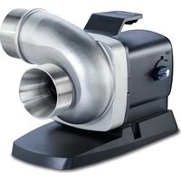
natural_image
Black plastic water purifier with a vertical stand and side knob (no text or symbols visible)Aquarius Fountain Set Eco
5500, 7500, 9500
EN Operating instructions
FR Notice d'emploi
ARS0019
Gerät aufstellen
! WARNING
ARS0015
! VORSICHT
Environmental Function Control (EFC)
Gerät zusammenbauen
So gehen Sie vor:
ARS0019
Lagern/Überwintern
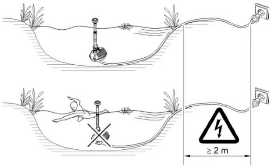
▶ Disconnect all electrical devices in the water from the power supply before reaching into the water. Otherwise there is a risk of severe injuries or death by electrocution.
This unit can be used by children aged 8 and above and by persons with reduced physical, sensory or mental capabilities or lack of experience and knowledge if they are supervised or have been instructed on how to use the unit in a safe way and they understand the hazards involved. Do not allow children to play with the unit. Only allow children to carry out cleaning and user maintenance under supervision.
Safety information
Electrical connection
- Special regulations apply for electrical installation in outdoor spaces. Only a qualified electrician may perform the electrical installation.
- The qualified electrician has the necessary professional training, knowledge and experience to perform electrical installation in outdoor spaces. The electrician can detect potential dangers and knows how to adhere to regional and national standards, regulations and directives.
— For your own safety, please consult a qualified electrician. - Only connect the unit if the electrical data of the unit and the power supply match.
- Only plug the unit into a correctly installed outlet.
- The device is to be supplied through a residual current device (RCD) having a rated residual operating current not exceeding 30 mA.
- Extension cables and power distributors (e.g. outlet strips) must be suitable for outdoor use (splash-proof).
- Protect open plugs and sockets from moisture.
Safe operation
- Operate the unit only when there are no people in the water.
- The impeller unit in the pump contains a magnet with a strong magnetic field that may affect the operation of pacemakers or implantable cardioverter defibrillators (ICDs). Keep a distance of at least 0.2 m between the implant and the magnet.
- Do not use the unit, if electrical lines or the housing are damaged.
- The supply cord cannot be replaced. If the cord is damaged, the appliance should be scrapped.
- Do not carry or pull the unit by its power cable.
- Route lines in such a way that they are protected from damage and do not present a tripping hazard.
- Never carry out technical changes to the unit.
- Only carry out work on the unit that is described in this manual.
- Only use original spare parts and accessories.
- Should problems occur, please contact the authorised customer service or OASE.
Intended use
Only use the product described in this manual as follows:
- For pumping normal pond water for water features and fountains.
- While adhering to the technical specifications. (→ Unit data)
- Adherence to the permissible water quality. (→ Permissible water quality)
The following restrictions apply to the unit:
- Do not use in swimming ponds.
- Never use the unit with fluids other than water.
- Never run the unit without water.
- Do not use for commercial or industrial purposes.
- Do not connect to the domestic water supply.
- Do not use in conjunction with chemicals, foodstuff, easily flammable or explosive substances.
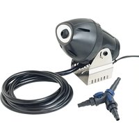
Product Description
Overview
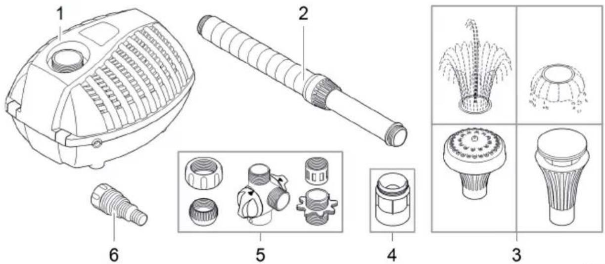
Aquarius Fountain Set Eco 5500, 7500, 9500
| 1 | Fountain pump |
| 2 | Telescopic extension |
| 3 | Nozzles |
| 4 | Transition piece with fine filter screen |
| 5 | Flow regulator, ball joint with union nut, transition piece,sleeve, double nipple |
| 6 | Stepped hose adapter |
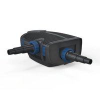
Properties
Aquarius Fountain Set Eco 5500, 7500, 9500 is a fountain pump for garden ponds, ornamental fountains and water courses.
- Temperature protection by integrated temperature monitor.
- Pivoting telescopic extension with various nozzles.
• Second, separately adjustable outlet.
Symbols on the unit


The unit is dust-tight and water-tight down to 2 m.

Remove the unit in the event of freezing temperatures.

Danger for persons with pacemakers. The unit contains a strong magnet.

Do not dispose of the unit with the normal household waste.

Read the operating instructions.
Installation and connection
Reassembling the unit
How to proceed:
- Fit the sleeve, flow regulator, double nipple, union nut, ball joint and transition piece together and screw onto the pump outlet.
- Screw the telescopic extension with the desired nozzle onto the flow regulator.
- Screw the stepped hose adapter onto the flow regulator for feeding a water course if applicable.
- Align the telescopic extension and hand tighten the union nut on the ball joint.
ARS0019
Installing the unit

WARNING
Severe injuries or death due to operation of this unit in a swimming pond. Defective electrical components will electrify the water with dangerous electrical voltage.
▶ Never operate the unit in a swimming pond.
NOTE
If the pump is used for conveying excessively soiled water, the impeller unit will be subject to increased wear and will require earlier replacement.
▶ Thoroughly clean the pond or pool before installing the pump.
▶ Install the pump at a raised level above the bottom. This reduces intake of muddy water.
How to proceed:
- Install the unit in the pond in a horizontal position on firm, sludge-free ground and ensure that it is completely covered with water.
ARS0015
Commissioning/start-up
CAUTION
Risk of injury due to unexpected start-up. Internal monitoring functions may switch off the unit and automatically reactivate it.
▶ Disconnect the power plug before carrying out any work on the unit.
NOTE
The unit will be destroyed if it is operated with a dimmer. It contains sensitive electrical components.
▶ Do not connect the unit to a dimmable power supply.
Switching ON/OFF
- Switching on: Plug the power plug into the outlet. - The unit switches on immediately.
- Switching off: Pull the power plug from the outlet.
Environmental Function Control (EFC)
When started up and then every 20 ... 40 minutes the pump automatically performs a pre-programmed self-test (Environmental Function Control (EFC)). The pump detects if it is running dry / clogged or submerged. The pump shuts down automatically after 60 to 120 seconds if it runs dry/is blocked. In the event of a malfunction, disconnect the power supply and “flood the pump” or remove the obstacle. Afterwards, the unit can be restarted.
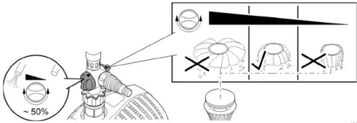
Setting the flow rate
Setting the spray pattern and flow rate:
- Adjust the flow regulator so that the nozzle produces the desired spray pattern.
- Adjust the flow regulator to achieve the desired flow rate for the water course.
ARS0022
Maintenance and cleaning
CAUTION
Risk of injury due to unexpected start-up. Internal monitoring functions may switch off the unit and automatically reactivate it.
▶ Disconnect the power plug before carrying out any work on the unit.
NOTE
Do not use aggressive cleaning agents or chemical solutions. These agents can damage the housing, impair the function of the device and harm animals, plants and the environment.
▶ If possible, clean the unit with clear water and a soft brush or a sponge; remove stubborn dirt with the aid of the recommended cleaning agents.
Cleaning the device
i Clean the unit as required but at least twice per year.
- When cleaning the pump, pay particular attention to the impeller unit and the pump housing.
- Recommended cleaning agent for removing stubborn limescale deposits:
- Pump cleaning agent PumpClean from OASE.
— Vinegar- and chlorine-free household cleaning agent.
• After cleaning, thoroughly rinse all parts in clean water.
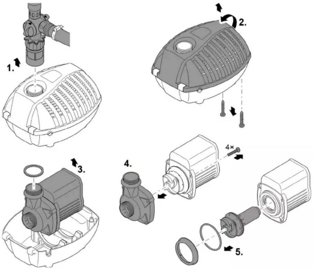
Cleaning the pump
How to proceed:
- Unscrew the transition piece.
- Remove the two screws and open the filter housing.
- Take out the pump.
- Remove the screws of the pump casing and pull off the pump casing.
- Pull out the impeller unit (magnetic resistance).
- Clean all parts.
ARS0018
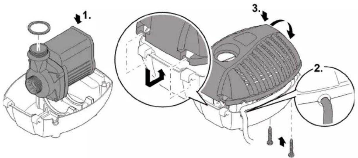
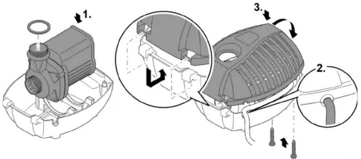
Reassembling the unit
How to proceed:
- Place the pump into the strainer casing.
- Route the connection cable through the cable opening in the filter housing.
- Replace the filter cover, turn in the two screws and hand tighten.
- Screw on the transition piece together with the flat seal.
ARS0019
Storage/winter protection
The unit is not frost-proof and has to be removed and put into storage if minus temperatures are expected.
How to correctly store the unit:
• Thoroughly clean the unit.
- Check the unit for damage and replace damaged components.
- Store the pump submerged and in a frost-free environment.
- Protect open plug connections from moisture and dirt.
Malfunction remedy
| Malfunction | Cause | Remedy |
| Pump does not start | No mains voltage | Check the mains voltage.Check supply lines. |
| Pump does not deliver. | Filter housing clogged | Clean strainer casings |
| Excessively soiled water | Clean the pump. The pump automatically switches on again once the motor has cooled down. | |
| The impeller unit is blocked | Disconnect the powersupply and remove obstacle. Then switch the pump on again. | |
| Fountain height insufficient or inconsistent | Filter/screen soiled or clogged | Clean filter/screen |
| Main flow regulator closed too far | Adjust main flow regulator | |
| Nozzle blocked | Clean nozzle/screen | |
| Impeller unit soiled | Clean | |
| Hose clogged or defective | Clean/replace hose | |
| Hose kinked | Check hose and replace if necessary | |
| Excessive loss due to friction in the hose | Reduce hose length to reduce frictional loss | |
| Rotor worn | Replace rotor | |
| Pump switches off after a short running period. | Excessively soiled water | Clean the pump. The pump automatically switches on again once the motor has cooled down. |
| Water temperature too high | Note maximum water temperature of +35°C. The pump automatically switches on again once the motor has cooled down. | |
| The impeller unit is blocked | Disconnect the power supply and remove obstacle. Then switch the pump on again. | |
| Pump has run dry. | Disconnect the power plug and flood the pump. Fully submerge the pump for operation in the pond. Then switch the pump on again. |
EN
Technical data
Unit data
| Aquarius Fountain Set Eco | 5500 | 7500 | 9500 | ||
| Connection voltage | AC V | 220 ... 240 | 220 ... 240 | 220 ... 240 | |
| Mains frequency | Hz | 50 | 50 | 50 | |
| Power consumption | W | 70 | 85 | 125 | |
| Protection type | IP 68 | IP 68 | IP 68 | ||
| Max. pump capacity | l/h | 5500 | 7500 | 9500 | |
| Max. water column | m | 3.8 | 4.0 | 5.2 | |
| Max. pump immersion depth | m | 2 | 2 | 2 | |
| Connection, pressure side | G 112 | G 112 | G 112 | ||
| Connection, suction side | G 112 | G 112 | G 112 | ||
| Connection for hose | mm | 19, 25, 32, 38 | 13/19/25 | 13/19/25 | |
| Telescopic nozzle extension | mm | 300 ... 520 | 300 ... 520 | 300 ... 520 | |
| Filter supply surface area | cm ^2 | 400 | 400 | 400 | |
| Length of power cable | m | 10 | 10 | 10 | |
| Dimensions | Length | mm | 290 | 290 | 290 |
| Width | mm | 230 | 230 | 230 | |
| Height | mm | 180 | 180 | 180 | |
| Weight | kg | 5.0 | 5.0 | 5.9 | |
Permissible water quality
Fresh water, pond water
| pH value | 6.8 ... 8.5 | |
| Hardness | °dH | 8 ... 15 |
| Free chlorine | mg/l | <0.3 |
| Chloride content | mg/l | <250 |
| Salt content | % | <0.4 |
| Overall dry residue | mg/l | <50 |
| Temperature | °C | +4 ... +35 |
Wear parts
- Impeller unit
EN
Disposal
NOTE
Do not dispose of this unit with household waste.
▶ Dispose of the unit by using the return system provided for this purpose.
▶ Should you have questions, please contact your local disposal company. They will give you information on how to correctly dispose of the unit.
▶ Render the unit unusable by cutting the cables.

AVERTISSEMENT
ARS0019
ARS0015
Mise en service

PRUDENCE
Environmental Function Control (EFC)
ARS0019
natural_image
Mechanical assembly diagram showing a motor component with a circular head and threaded shaft (no text or labels)
ARS0019
Apparaat opstellen

WAARSCHUWING
ARS0015
Ingebruikname
VOORZICHTIG
Environmental Function Control (EFC)
ARS0019
Opslag/overwinteren
ARS0019
ARS0015
Puesta en marcha
CUIDADO
Environmental Function Control (EFC)
ARS0018
Montaje del equipo
ARS0019
ARS0019
Posicionar o aparelho

AVISO
ARS0015
Environmental Function Control (EFC)
ARS0018
ARS0019
Armazenar/Invernar
natural_image
3D mechanical assembly diagram showing a motor housing with a knob and mounting bracket (no text or symbols)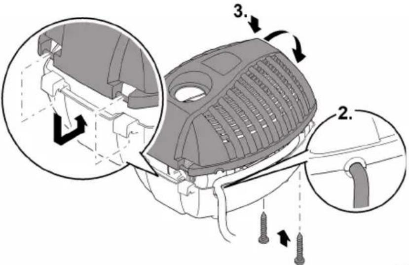
ARS0019
Installare l'apparecchio

AVVERTENZA
ARS0015
Messa in funzione

ATTENZIONE
Environmental Function Control (EFC)
ARS0019
Aquarius Fountain Set Eco 5500, 7500, 9500
ARS0019
ARS0015
Ibrugtagning
! FORSIGTIG
Environmental Function Control (EFC)
ARS0019
Opbevaring/overvintring
ARS0019
ARS0015
Igangsetting
! FORSIKTIG
Environmental Function Control (EFC)
ARS0019
Lagring/overvintring
ARS0019
Installera apparaten

WARNING
ARS0015
Driftstart
OBS
Environmental Function Control (EFC)
Montera samman apparaten
Gör så här:
ARS0019
Aquarius Fountain Set Eco 5500, 7500, 9500
ARS0019
Laitteen asennus

VAROITUS
ARS0015
Käyttöönotto
HUOMIO
Environmental Function Control (EFC)
Laitteen kokoaminen
Toimit näin:
ARS0019
Aquarius Fountain Set Eco 5500, 7500, 9500
ARS0019
ARS0015
Üzembe helyezés
! VIGYÁZAT
Environmental Function Control (EFC)
ARS0018
ARS0019
Tárolás/Telelés
ARS0019
ARS0015
Rozruch
OSTROŻNIE
Environmental Function Control (EFC)
Montaż urządzenia
ARS0019
Aquarius Fountain Set Eco 5500, 7500, 9500
ARS0019
Instalace prístroje

VAROVÁNÍ
ARS0015
Uvedení do provozu
POZOR
Environmental Function Control (EFC)
ARS0018
Sestavení prístroje
ARS0019
Uložení/zazimování
Aquarius Fountain Set Eco 5500, 7500, 9500
ARS0019
ARS0015
Environmental Function Control (EFC)
ARS0018
ARS0019
Uloženie/prezimovanie
Aquarius Fountain Set Eco 5500, 7500, 9500
ARS0019
Postavitev naprave

OPOZORILO
ARS0015
Zagon

PREVIDNO
Environmental Function Control (EFC)
ARS0018
Sestavi napravo
ARS0019
Aquarius Fountain Set Eco 5500, 7500, 9500
ARS0019
Postavljanje uređaja

UPOZORENJE
ARS0015
Stavljanje u pogon

OPREZ
Environmental Function Control (EFC)
Pumpa prilikom stavljanja u pogon, a zatim tijekom rada svakih 20 ... 40 minuta automatski obavlja unaprijed programiranu samoprovjeru (Environmental Function Control (EFC)). Pumpa prepoznaje radi li pritom na suho, je li blokirana ili uronjena. U slučaju rada na suho ili blokiranja, pumpa se automatski isključuje nakon otprilike 60 do 120 sekundi. U slučaju neispravnosti prekinite dovod elektroenergije i „potopite pumpu“ ili uklonite prepreku. Nakon toga možete uređaj ponovno staviti u pogon.
Namještanje količine protoka
ARS0018
Sastavljanje uređaja
ARS0019
ARS0019
ARS0015
Environmental Function Control (EFC)
ARS0018
RO
ARS0019
ARS0019
ARS0015
Environmental Function Control (EFC)
ARS0018
Сглобяване на уреда
ARS0019
Aquarius Fountain Set Eco 5500, 7500, 9500
natural_image
Mechanical component diagram showing a motor assembly with a knob and housing (no text or symbols)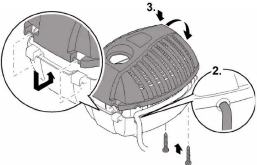
ARS0019
UK
ARS0015
Environmental Function Control (EFC)
ARS0018
UK
Збирання приладу
ARS0019
ARS0019
RU
ARS0015
Пуск в эксплуатацию
ОСТОРОЖНО
Environmental Function Control (EFC)
ARS0018
RU
Сборка прибора
ARS0019
ARS0019
安装设备
警告
ARS0015
调试
小心
Environmental Function Control (EFC)
组装设备
步骤如下:
ARS0019
存放/过冬

- Aquarius Fountain Set Eco
- Gerät aufstellen
- ! WARNING
- ! VORSICHT
- Environmental Function Control (EFC)
- Gerät zusammenbauen
- Lagern/Überwintern
- Safety information
- Electrical connection
- Safe operation
- Intended use
- Product Description
- Overview
- Properties
- Symbols on the unit
- Installation and connection
- Reassembling the unit
- Installing the unit
- WARNING
- NOTE
- Commissioning/start-up
- CAUTION
- Switching ON/OFF
- Setting the flow rate
- Maintenance and cleaning
- Cleaning the device
- Cleaning the pump
- Storage/winter protection
- Technical data
- Unit data
- Permissible water quality
- Wear parts
- Disposal
- AVERTISSEMENT
- Mise en service
- PRUDENCE
- Apparaat opstellen
- WAARSCHUWING
- Ingebruikname
- VOORZICHTIG
- Opslag/overwinteren
- Puesta en marcha
- CUIDADO
- Montaje del equipo
- Posicionar o aparelho
- AVISO
- Armazenar/Invernar
- Installare l'apparecchio
- AVVERTENZA
- Messa in funzione
- ATTENZIONE
- Ibrugtagning
- ! FORSIGTIG
- Opbevaring/overvintring
- Igangsetting
- ! FORSIKTIG
- Lagring/overvintring
- Installera apparaten
- Driftstart
- OBS
- Montera samman apparaten
- Laitteen asennus
- VAROITUS
- Käyttöönotto
- HUOMIO
- Laitteen kokoaminen
- Üzembe helyezés
- ! VIGYÁZAT
- Tárolás/Telelés
- Rozruch
- OSTROŻNIE
- Montaż urządzenia
- Instalace prístroje
- VAROVÁNÍ
- Uvedení do provozu
- POZOR
- Sestavení prístroje
- Uložení/zazimování
- Uloženie/prezimovanie
- Postavitev naprave
- OPOZORILO
- Zagon
- PREVIDNO
- Sestavi napravo
- Postavljanje uređaja
- UPOZORENJE
- Stavljanje u pogon
- OPREZ
- Namještanje količine protoka
- Sastavljanje uređaja
- Сглобяване на уреда
- Збирання приладу
- Пуск в эксплуатацию
- ОСТОРОЖНО
- Сборка прибора
- 安装设备
- 警告
- 调试
- 小心
- 组装设备
- 存放/过冬
Brand : OASE
Model : Aquarius Fountain Set Eco 9500
Category : Water pump