AquaMax Eco Titanium 33000 - Water pump OASE - Free user manual and instructions
Find the device manual for free AquaMax Eco Titanium 33000 OASE in PDF.

| Product type | Pond water pump |
| Brand | OASE |
| Model | AquaMax Eco Titanium 33000 |
| Dimensions (L x W x H) | 275 x 176 x 200 mm |
| Weight | 9,2 kg |
| Connection voltage | 220-240 V AC |
| Network frequency | 50/60 Hz |
| Power consumption | 30 to 145 W |
| Max flow rate | 33000 l/h |
| Max delivery head | 3,5 m |
| Max immersion depth | 4 m |
| Cable length | 10 m |
| Admissible water temperature (submerged) | +4 to +35 °C |
| Protection rating | IP68 (dust-tight and waterproof up to 4 m) |
| Inlet / outlet connection | G2 1/2 (DN63) |
| Max impurity diameter | 6 mm |
| SFC function (Seasonal Flow Control) | Yes – automatic flow adaptation according to water temperature |
| Control compatibility | Eco Control (accessory) and OASE Control network |
| Pump housing material | Titanium |
| Use | Submerged or dry (out of water) |
| Wear parts | Operating unit (rotor), bearing in the motor block |
| Recommended cleaning | At least 2 times per year, clear water and soft brush; descaling agent PumpClean OASE |
| Required electrical protection | Residual current device (RCD) 30 mA max |
| Warranty | See the complete manual for conditions |
Frequently Asked Questions - AquaMax Eco Titanium 33000 OASE
User questions about AquaMax Eco Titanium 33000 OASE
0 question about this device. Answer the ones you know or ask your own.
Ask a new question about this device
Download the instructions for your Water pump in PDF format for free! Find your manual AquaMax Eco Titanium 33000 - OASE and take your electronic device back in hand. On this page are published all the documents necessary for the use of your device. AquaMax Eco Titanium 33000 by OASE.
USER MANUAL AquaMax Eco Titanium 33000 OASE
natural_image
Metal pipe fitting with threaded end and black base (no visible text or symbols)AquaMax Eco Titanium
33000
EN Operating instructions
FR Mode d'emploi
natural_image
Technical illustration of a mechanical device with a warning symbol and magnified inset showing internal components (no text or labels)AMX0230

AMX0229
Inbetriebnahme
DE
ACHTUNG
Environmental Function Control (EFC)
About these operating instructions
These operating instructions are valid for:
Product name
Item number
AquaMax Eco Titanium 33000
95095, 95910
Original manual.
Safety information
Electrical connection
- Special regulations apply for electrical installation in outdoor spaces. Only a qualified electrician may perform the electrical installation.
- The qualified electrician has the necessary professional training, knowledge and experience to perform electrical installation in outdoor spaces. The electrician can detect potential dangers and knows how to adhere to regional and national standards, regulations and directives.
— For your own safety, please consult a qualified electrician. - Only connect the unit if the electrical data of the unit and the power supply match.
- Only plug the unit into a correctly installed outlet.
- The device is to be supplied through a residual current device (RCD) having a rated residual operating current not exceeding 30 mA.
- Extension cables and power distributors (e.g. outlet strips) must be suitable for outdoor use (splash-proof).
- Protect open plugs and sockets from moisture.
Safe operation
- Disconnect all electrical devices in the water from the power supply before reaching into the water. Otherwise there is a risk of severe injuries or death by electrocution.
- Do not use the unit, if electrical lines or the housing are damaged.
- The supply cord cannot be replaced. If the cord is damaged, the appliance should be scrapped.
- The impeller unit in the pump contains a magnet with a strong magnetic field that may affect the operation of pacemakers or implantable cardioverter defibrillators (ICDs). Keep a distance of at least 0.2 m between the implant and the magnet.
- Never pull on electric cables. In particular, never carry units on their cables.
- Route lines in such a way that they are protected from damage and do not present a tripping hazard.
- Never carry out technical changes to the unit.
- This unit can be used by children aged 8 and above and by persons with reduced physical, sensory or mental capabilities or lack of experience and knowledge if they are supervised or have been instructed on how to use the unit in a safe way and they understand the hazards involved. Do not allow children to play with the unit. Cleaning and user maintenance shall not be carried out by children unless they are aged from 8 years and above and supervised.
- Only carry out work on the unit that is described in this manual.
- Only use original spare parts and accessories.
- Should problems occur, please contact the authorised customer service or OASE.
Intended use
Only use the product described in this manual as follows:
- For pumping normal pond water for filter systems, waterfall systems and water course systems.
- While adhering to the technical specifications. (→ Unit data)
- Adherence to the permissible water quality. (→ Permissible water quality)
The following restrictions apply to the unit:
- Do not use in swimming ponds.
- Never run the unit without water.
- Do not use the unit together with chemicals, food, flammable, explosive substances or other liquids aside from water.
- Do not connect to the domestic water supply.
- Do not use for industrial purposes.
- According to EMC (Electromagnetic Compatibility), this is a class A unit. The unit may cause malfunctions in living environments. It is the user's responsibility to take suitable counter-measures.
Product Description
Overview
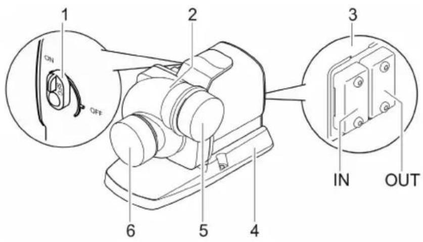
AMX0224
1 Switch Seasonal Flow Control (SFC) on/off
- This switch has no effect if a control system is connected. The SFC is then switched on or off using the control system.
2 Pump casing
The pump casing can be turned by 90°.
3 Control system connection
- The OASE Eco Control unit (accessory) is required for operating the pump.
• Alternatively, the pump can be integrated in an OASE Control network. - For information on OASE Control, visit www.oase.com.
4 Stand
Ensures a stable position. Screwing the stand to the ground is possible.
5 Outlet
(Pressure socket)
Keep the protective caps.
To prevent serious injury while the pump is running, immediately attach the protective cap after you have removed a connected pipe.
6 Inlet
(Suction socket)
Symbols on the unit
IP68

The unit is dust-tight and water-tight down to 4 m.
EN

Protect the unit from direct sunlight.

Do not dispose of the unit with normal household waste.

Read the operating instructions.
Seasonal Flow Control (SFC)
The SFC function intelligently controls the water volume or pump head based on the water temperature. This means the pump adapts to the individual pond ecology throughout the year and supports the pond biology through temperature-dependent circulation (winter mode, transition mode and summer mode).
- If the SFC function is active, the pump differentiates between ...
- Winter mode, minimum (water temperature lower than +10 °C)
- Transition mode, medium (water temperature +10 - ... +17 °C)
— Summer mode, maximum (water temperature greater than +17 °C)
You can find the specific parameters at www.oase.com in the product section "Pond pumps".
- The SFC function may only be activated if the pump is submersed!
- If a skimmer or satellite filter is used, it may, depending on the system, be advisable to deactivate the SFC function.
- The SFC function is deactivated on delivery.
Technical data
Unit data
| Description | AquaMax Eco Titanium 33000 | ||
| Connection voltage | V AC | 220 - 240 | |
| Mains frequency | Hz | 50/60 | |
| Power consumption | W | 30 - 145 | |
| Control using | Oase Control (OC), Eco Control | ||
| Inlet | Connection thread | G2 12 | |
| for pipe | DN63 | ||
| Outlet | Connection thread | G2 12 | |
| for pipe | DN63 | ||
| Permissible water temperature range (immersed in-stallation) | °C | +4 ... +35 | |
| Max. permissible ambient temperature with natural convection (dry installation) | °C | +30 | |
| Max. permissible ambient temperature with forced cooling (dry installation) | °C | +40 | |
| Max. pump capacity | l/h | 33000 | |
| Max. pump head | m | 3.5 | |
| Max. particle size, coarse dirt particles | mm | 6 | |
| Max. immersion depth | m | ≤4 | |
| Cable length | m | 10 | |
| Dimensions | Length | mm | 275 |
| Width | mm | 176 | |
| Height | mm | 200 | |
| Weight | kg | 9.2 | |
Characteristic curves of the pump
(→ Pump characteristic curves, 354)
Permissible water quality
| Type | Fresh water | Pool water | Salt water | |
| pH value | 6.8 ... 8.5 | 7.2 ... 8.3 | 7.5 ... 8.5 | |
| Hardness | DH | 8 ... 15 | 8 ... 15 | 20 ... 30 |
| Free chlorine | mg/l | <0.3 | <0.6 | <0.3 |
| Chloride content | mg/l | <250 | <250 | <22000 |
| Salt content | % | <0.4 | <0.4 | <4 |
| Overall dry residue | mg/l | <50 | <50 | <50 |
| Temperature | °C | +4 ... +35 | +4 ... +30 | +4 ... +28 |
Installation and connection
The pump can be installed submerged (in water) or dry (outside the water).
The use of the pump is only permitted with observance of the specified water quality.
(→ Permissible water quality)
- Pool water or salt water can impair the appearance of the unit. Such impairments are excluded from the guarantee.

WARNING
Severe injuries or death due to operation of this unit in a swimming pond. Defective electrical components will electrify the water with dangerous electrical voltage.
▶ Never operate the unit in a swimming pond.

CAUTION
Rotating components in the intake and pressure socket area. Risk of injury when reaching into the sockets.
In particular, observe the following: A unit that has stopped due to overload can start up unexpectedly!
▶ Do not reach into the opening of the intake socket or pressure socket while the power plug is plugged in.
▶ If the sockets are freely accessible during operation, e.g. if no hoses are connected, use a hand guard to secure the sockets. The hand guard is available as an accessory.
Avoid exposing any unit components to direct sunlight for extended periods of time, as this can lead to damage. If necessary, use a protective cover.
Turning the pump casing to achieve a different position
NOTICE
If the pump housing jams when it is removed and pushes against the impeller unit, this will damage the impeller unit.
▶ Position the pump vertically before removing the pump housing. This ensures that the weight of the pump housing can no longer push against the impeller unit.
▶ Carefully pull the motor block off the pump housing, ensuring that it is kept straight.
▶ Proceed equally carefully during assembly.
If necessary, the pump casing can be turned to change the position of the pump outlet by 90^ .
- The pump casing can only be mounted in the two positions indicated.
- Reassemble the pump in the reverse order.
— Tightening torque for all loosened screws: 3 Nm
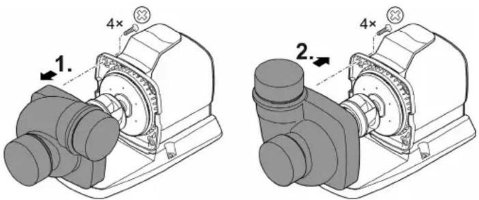
AMX0227
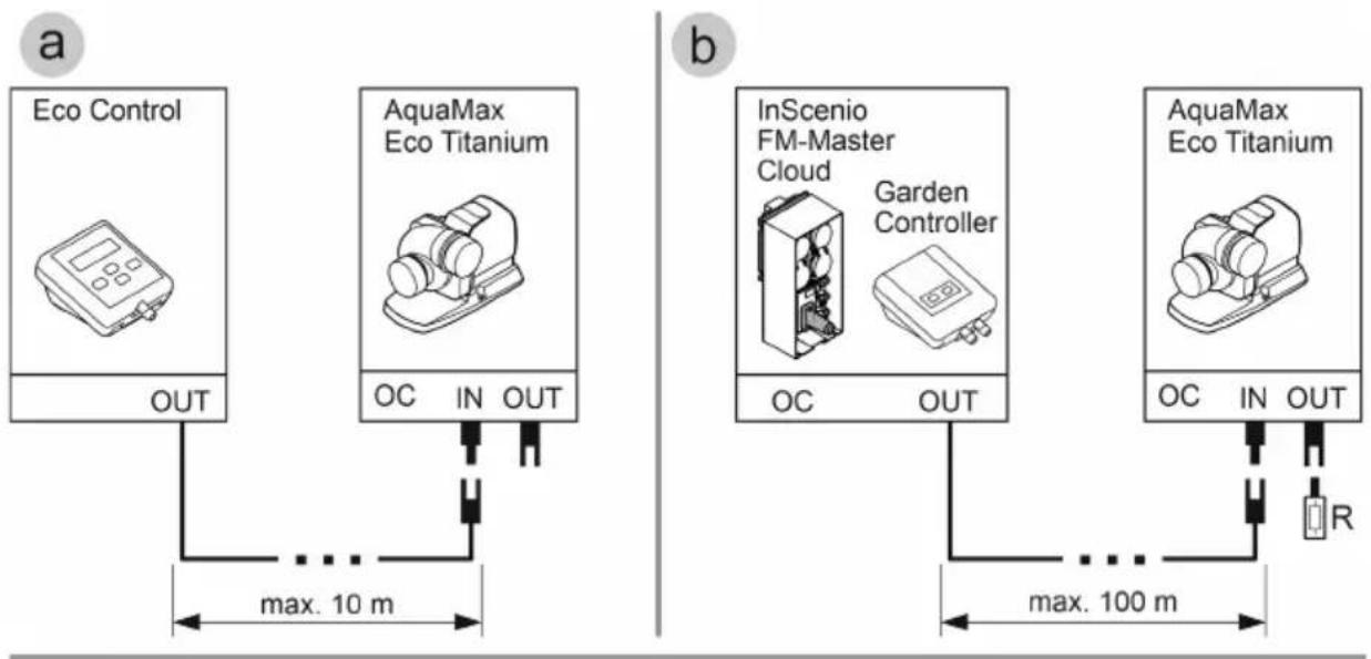
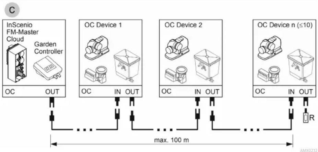
Connecting the control system
The pump can be operated with or without the control system.
- The control system makes it possible to regulate the pump power.
- Without the control system, the pump runs permanently at full power.
Compatible control systems (accessories):
- Eco Control
Intelligent control system for one pump.
- Incenio FM-Master Cloud
Garden Controller Cloud
Up to 10 OASE Control-compatible units (pumps, filters, lights) can be controlled using the "OASE Control" app.
For information on this topic, visit www.oase.com and navigate to the section "Smart garden controls and lighting".
flowchart
graph TD
    subgraph_a["ECO Control"]
        A1["ECO Control"] --> OUTOUT
        OUTOUT -->|max. 10 m| A2["AquaMax Eco Titanium"]
        A2 --> OCINOUT
    end
    subgraph_b["InScenio FM-Master Cloud"]
        B1["InScenio FM-Master Cloud"] --> OCOUTOUT
        OCOUTOUT -->|max. 100 m| B2["AquaMax Eco Titanium"]
        B2 --> OCINOUT
        OCINOUT -->|max. 100 m| B3["AquaMax Eco Titanium"]
    end
flowchart
graph LR
    A["InScenio FM-Master Cloud"] -->|OC OUT| B["..."]
    C["Garden Controller"] -->|OC OUT| D["..."]
    E["OC Device 1"] -->|OC IN OUT| F["..."]
    G["OC Device 2"] -->|OC IN OUT| H["..."]
    I["OC Device n (≤10)"] -->|OC IN OUT| J["..."]
    B --> K["max. 100 m"]
    D --> K
    F --> K
    H --> K
    J --> K
    K --> L["AMX0232"]
- An OASE Control network (variant B, C) must end with a terminal resistor R. The terminal resistor is included with the InSenio FM-Master or Garden Controller.
NOTICE
The unit will be damaged, if water enters the plug connector.
▶ Connect the plug connector or place the protective cap on it.
▶ Ensure that the rubber seal is clean and fits exactly.
▶ If the rubber seal is damaged, it must be replaced. When the plug connector is disconnected, the rubber seal must be replaced if it is older than 2 years.
▶ Always secure the plug connector or the protective cap with the two screws.
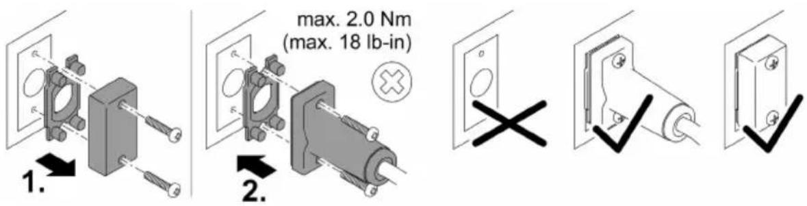
PLX0004
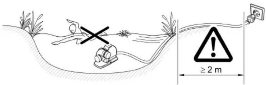
Submerged installation of the pump
- Ensure that the power cables and mains sockets are at least 2 m from the water.
- For installation of the pump in a pump chamber (recommended):
- For a swimming pond or pool frequented by swimming people, install the pump chamber at least 2 m from the water.
-
Install the pump horizontally.
— Screw the stand to the floor of the pump chamber to ensure the stability of the pump. -
For installation of the pump without a pump chamber:
— Place the pump horizontally on a stable, mud-free surface. - Ensure secure and stable positioning of the pump.
- Only operate the pump when it is fully submerged.
- For muddy or soiled water, we recommend installing the pump or intake-side components (skimmer, satellite filter, base outlet, etc.) above ground level. This decreases intake of particles and increases the service life of the impeller unit.
AMX022 ^®
Dry installation of the pump
- Ensure that the power cables and mains sockets are at least 2 m from the water.
- For a swimming pond or pool frequented by swimming people, install the pump at least 2 m from the water.
- Place the pump horizontally on a stable surface.
- Ensure secure and stable positioning of the pump. If necessary, screw the stand to the ground.
- Protect the pump from direct sunlight.
- Adhere to the maximum permissible ambient temperature. If necessary, provide forced cooling. (→ Gerätedaten)

AMX0226
Connecting the pressure side/suction side

WARNING
The impeller unit rotates very fast. Do not reach into the openings of the suction socket or pressure socket as there is a risk of severe injury such as loss of limb.
- Secure the suction socket/pressure socket with a hand guard if no pipe is connected. The hand guard is available as an accessory.
▶ Place the pump in a pump chamber. Protect the pump chamber against unauthorised access (use a padlock or screws to secure the access).
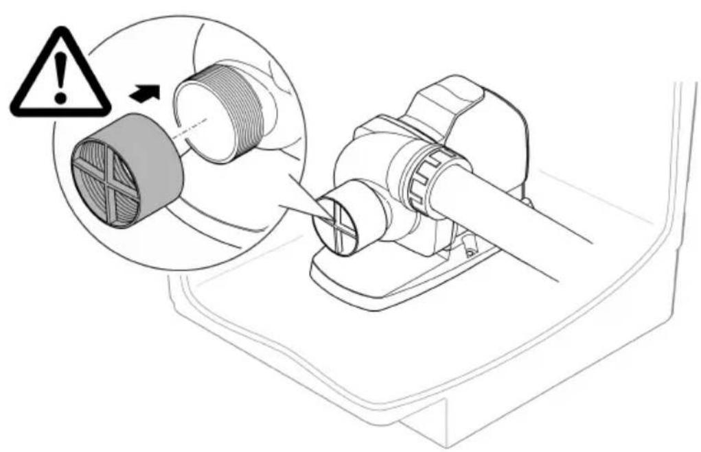
AMX0230

AMX0229
Commissioning/start-up
NOTICE
The unit will be destroyed if it is operated with a dimmer. It contains sensitive electrical components.
▶ Do not connect the unit to a dimmable power supply.
NOTICE
Never allow the pump to run dry. Otherwise the pump may be destroyed.
▶ Only operate the pump when it is submerged or flooded.
Switching ON/OFF
- Switching on: Plug the power plug into the outlet.
— The unit switches on immediately.
- Switching off: Pull the power plug from the outlet.
Environmental Function Control (EFC)
When started up and then every 20 ... 40 minutes the pump automatically performs a pre-programmed self-test (Environmental Function Control (EFC)). The pump detects if it is running dry / clogged or submerged. The pump shuts down automatically after 60 to 120 seconds if it runs dry/is blocked. In the event of a malfunction, disconnect the power supply and "flood the pump" or remove the obstacle. Afterwards, the unit can be restarted.
Maintenance and cleaning

CAUTION
Risk of injury due to unexpected start-up. Internal monitoring functions may switch off the unit and automatically reactivate it.
▶ Disconnect the power plug before carrying out any work on the unit.
Cleaning the device
NOTICE
Do not use aggressive cleaning agents or chemical solutions. These agents can damage the housing, impair the function of the device and harm animals, plants and the environment.
▶ If possible, clean the unit with clear water and a soft brush or a sponge; remove stubborn dirt with the aid of the recommended cleaning agents.
i Clean the unit as required but at least twice per year.
- When cleaning the pump, pay particular attention to the impeller unit and the pump housing.
- Recommended cleaning agent for removing stubborn limescale deposits:
— Pump cleaning agent PumpClean from OASE.
— Vinegar- and chlorine-free household cleaning agent.
• After cleaning, thoroughly rinse all parts in clean water.
Cleaning/replacing the impeller unit

WARNING
The impeller unit rotates very fast. Do not reach into the openings of the suction socket or pressure socket as there is a risk of severe injury such as loss of limb.
▶ Disconnect the power plug before carrying out any work on the unit.
NOTICE
The impeller unit is guided in the motor block by a bearing. This bearing is a wear part and should be changed at the same time as the impeller unit.
▶ Changing the bearing requires specialist knowledge and tools. Have the bearing changed by the OASE specialist dealer or send the pump to OASE.
NOTICE
The impeller unit contains strong magnets that attract magnetic particles (e.g. iron filings). Any remaining particles can cause irreparable damage to the impeller unit and motor block.
▶ Carefully remove any adhering particles from the impeller unit prior to installation.
NOTICE
If the pump housing jams when it is removed and pushes against the impeller unit, this will damage the impeller unit.
▶ Position the pump vertically before removing the pump housing. This ensures that the weight of the pump housing can no longer push against the impeller unit.
▶ Carefully pull the motor block off the pump housing, ensuring that it is kept straight.
▶ Proceed equally carefully during assembly.
- Remove the pipes on the suction side and on the pressure side.
- Use a wide-blade screwdriver to carefully lever out the impeller unit if necessary.
• After removing the impeller unit, clean all parts under running tap water.
— Replace a worn or damaged impeller unit. - Assemble the pump in the reverse order.
- Tightening torque for all loosened screws: 3 Nm.
- Dismantle the motor block as shown in the figure.
- Use a brush under clear water to clean the components.
- Check all components for damage. Replace damaged or worn components.
- Reassemble the motor block in reverse order.
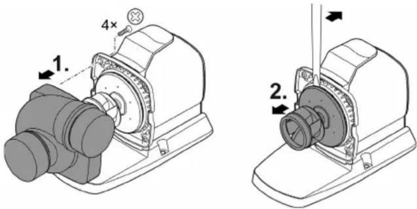
AMX0228
Storage/winter protection
The unit is not frost-proof and has to be removed and put into storage if minus temperatures are expected.
How to correctly store the unit:
• Thoroughly clean the unit.
- Check the unit for damage and replace damaged components.
- Store the pump submerged and in a frost-free environment.
- Protect open plug connections from moisture and dirt.
Malfunction remedy
| Malfunction | Possible cause | Remedy |
| Pump does not start | No mains voltage | Check the mains voltage.Check supply lines.Switch on the pump. |
| Pump does not transport fluid | Excessively soiled water | Clean the pump. The pump automatically switches on again once the motor has cooled down. |
| The impeller unit is blocked | Disconnect the power supply and remove obstacle. Then switch the pump on again. | |
| Insufficient delivered quantity | Impeller unit is running sluggishly | Clean the impeller unit |
| Excessive loss in the pipes due to friction | Select a larger pipe diameter.Reduce pipe length to the necessary minimum.Avoid unnecessary bends and connection elements. | |
| Pump switches off after operating briefly | Excessively soiled water | Clean the pump. The pump automatically switches on again once the motor has cooled down. |
| Water temperature too high | Note maximum water temperature of +35°C. The pump automatically switches on again once the motor has cooled down. | |
| Ambient temperature too high | Adhere to the maximum permissible ambient temperature. The pump automatically switches on again once the motor has cooled down. | |
| The impeller unit is blocked | Disconnect the power supply and remove obstacle. Then switch the pump on again. | |
| Pump has run dry. | Flood the pump. Fully submerge the pump for operation in the pond. |
Wear parts
- Impeller unit
- Bearing in the motor block
Spare parts
(→ Spare parts, 📄 356)
Disposal
NOTICE
Do not dispose of this unit with household waste.
▶ Dispose of the unit by using the return system provided for this purpose.
▶ Should you have questions, please contact your local disposal company. They will give you information on how to correctly dispose of the unit.
▶ Render the unit unusable by cutting the cables.
Garden Controller Cloud
natural_image
Three-step diagram showing a door hinge with a cross mark, a lock mechanism, and a checkmark (no text or symbols)PLX0004
AMX0230

AMX0229
Mise en service
AVIS
Environmental Function Control (EFC)
Garden Controller Cloud
AMX0230

AMX0229
Ingebruikname
LET OP
Environmental Function Control (EFC)
Garden Controller Cloud
AMX0230

AMX0229
Puesta en marcha
AVISO
Environmental Function Control (EFC)
Garden Controller Cloud
natural_image
Three technical diagrams showing a door hinge with cross mark and checkmark, no text or symbols presentPLX0004
AMX0230

AMX0229
Environmental Function Control (EFC)
Garden Controller Cloud
AMX0230

AMX0229
Messa in funzione
AVVISO
Environmental Function Control (EFC)
Garden Controller Cloud
Der kan styres op til 10 OASE Control-kompatible apparater (pumper, filter, lamper) via appen "OASE Control".
Du kan finde oplysninger herom på www.oase.com under emnet "Smart havestyring og belysning".
flowchart
graph TD
    subgraph a
        A["Eco Control"]
        B["AquaMax Eco Titanium"]
        C["OUT"] --> D["max. 10 m"]
        D --> E["AC"]
        F["AQUA Max Eco Titanium"] --> G["IN OUT"]
        G --> H["AC"]
        I["In Scenio FM-Master Cloud"] --> J["Garden Controller"]
        K["Out"] --> L["max. 100 m"]
        L --> M["AC"]
        N["AquaMax Eco Titanium"] --> O["IN OUT"]
        O --> P["R"]
    end
    subgraph b
        Q["In Scenio FM-Master Cloud"] --> R["Garden Controller"]
        S["Out"] --> T["max. 100 m"]
        T --> U["AC"]
        V["AquaMax Eco Titanium"] --> W["IN OUT"]
        W --> X["AC"]
        Y["In Scenio FM-Master Cloud"] --> Z["Garden Controller"]
        AA["Out"] --> AB["max. 100 m"]
        AB --> AC["AC"]
        AD["AquaMax Eco Titanium"] --> AE["IN OUT"]
        AE --> AF["R"]
    end

flowchart
graph LR
    A["InScenio FM-Master Cloud"] -->|OC OUT| B["..."]
    C["Garden Controller"] -->|OC OUT| D["..."]
    E["OC Device 1"] -->|OC IN OUT| F["..."]
    G["OC Device 2"] -->|OC IN OUT| H["..."]
    I["OC Device n (≤10)"] -->|OC IN OUT| J["..."]
    B --> K["max. 100 m"]
    D --> K
    F --> K
    H --> K
    J --> K
    K --> L["AMX0232"]
AMX0230

AMX0229
Ibrugtagning
BEMÆRK
Environmental Function Control (EFC)
(→ Reservedele, 📄 356)
Bortskaffelse
BEMÆRK
Garden Controller Cloud
Opptil 10 OASE Control-aktiverte apparater (pumper, filtre, lamper) kan styres via "OASE Control"-appen.
AMX0230

AMX0229
Igangsetting
LES DETTE
Environmental Function Control (EFC)
(→ Reservedeler, 📄 356)
Kassering
LES DETTE
Garden Controller Cloud
Upp till 10 st OASE Control-kompatibla apparater (pumpar, filter, lampor) kan styras med appen "OASE Control".
natural_image
Three-step diagram showing a door hinge with a cross mark, a roller pin, and a checkmark (no text or symbols)PLX0004
natural_image
Technical illustration of a mechanical device with a warning symbol and magnified inset showing internal components (no text or labels)AMX0230

AMX0229
Driftstart
OBS!
Environmental Function Control (EFC)
natural_image
Technical illustration of a mechanical device with a warning symbol and magnified inset showing internal components (no text or labels)AMX0230

AMX0229
Käyttöönotto
HUOMAUTUS
Environmental Function Control (EFC)
Garden Controller Cloud
AMX0230

AMX0229
Üzembe helyezés
ÉRTESÍTÉS
Environmental Function Control (EFC)
Garden Controller Cloud
natural_image
Three-step diagram showing a door lock with a cross mark, a roller roller, and a checkmark (no text or symbols)PLX0004
AMX0230

AMX0229
Rozruch
NOTYFIKACJA
Environmental Function Control (EFC)
AMX0230

AMX0229
Uvedení do provozu
OZNÁMENÍ
Environmental Function Control (EFC)
Garden Controller Cloud
AMX0230

AMX0229
Environmental Function Control (EFC)
AMX0230

AMX0229
Zagon
OBVESTILO
Environmental Function Control (EFC)
Garden Controller Cloud
AMX0230

HR
AMX0229
Stavljanje u pogon
OBAVIJEST
Environmental Function Control (EFC)
Pumpa prilikom stavljanja u pogon, a zatim tijekom rada svakih 20 ... 40 minuta automatski obavlja unaprijed programiranu samoprovjeru (Environmental Function Control (EFC)). Pumpa prepoznaje radi li pritom na suho, je li blokirana ili uronjena. U slučaju rada na suho ili blokiranja, pumpa se automatski isključuje nakon otprilike 60 do 120 sekundi. U slučaju neispravnosti prekinite dovod elektroenergije i „potopite pumpu“ ili uklonite prepreku. Nakon toga možete uređaj ponovno staviti u pogon.
Garden Controller Cloud
AMX0230

AMX0229
Environmental Function Control (EFC)
Garden Controller Cloud
AMX0230

AMX0229
Environmental Function Control (EFC)
Garden Controller Cloud
AMX0230

UK
AMX0229
Environmental Function Control (EFC)
Garden Controller Cloud
AMX0230
AMX0229
Пуск в эксплуатацию
УВЕДОМЛЕНИЕ
Environmental Function Control (EFC)
AMX0230

AMX0229
调试
注意
Environmental Function Control (EFC)
AMX0231
| 1 | 94999 | 2 | 98722 | 3 | 18068 | 4 | 6053 |
| 5 | 97209 | 6 | 40509 | 7 | 97208 | 8 | 48597 |