
TCM75EAP - String Trimmer HiKOKI - Free user manual and instructions
Find the device manual for free TCM75EAP HiKOKI in PDF.

| Product type | Thermal weed trimmer |
| Brand | HiKOKI |
| Model | TCM75EAP |
| Displacement (cm³) | 75.0 |
| Max engine power (kW) | 3.9 (according to ISO 7293) |
| Max engine speed (min⁻¹) | 9800 |
| Idle speed (min⁻¹) | 2500 |
| Fuel tank capacity (L) | 1.1 |
| Dry weight (kg) | 10.4 (without fuel, wheel and accessories) |
| Wheel type | Type 41 (abrasive or diamond) |
| Wheel outer diameter (mm) | 305 (12") or 355 (14") |
| Wheel arbor hole (mm) | 20 (25.4 with adapter collar) |
| Max abrasive wheel thickness (mm) | 3.5 (305 mm) / 4.0 (355 mm) |
| Max diamond wheel thickness (mm) | 3.5 |
| Min flange diameter (mm) | 101.7 |
| Wheel tightening torque (N·m) | 20 |
| Max spindle speed (min⁻¹) | 4200 |
| Sound pressure level LpA (dB(A)) | 99.5 (uncertainty 3.0) |
| Sound power level LwA (dB(A)) | 115 (uncertainty 3.0) |
| Front handle vibration level (m/s²) | 2.2 (uncertainty 1.0) |
| Rear handle vibration level (m/s²) | 2.7 (uncertainty 1.0) |
| Fuel | 2-stroke gasoline mixture (unleaded 89 octane) with oil 25:1 to 50:1 |
| Spark plug | NGK BPMR-7A, gap 0.6 mm |
| Starting | Manual with recoil starter, choke and primer pump |
| Transmission | Adjustable belt |
| Wet cutting | Possible with water supply (integrated valve) |
| Wheel guard | Tool-free adjustable |
| Anti-vibration | Anti-vibration springs |
| Maintenance | Air filter, spark plug, fuel filter, belt |
| Safety | Safety glasses, helmet, gloves, hearing protection, emergency stop |
| Spare parts | References available (e.g., 6699872, 6699868) |
Frequently Asked Questions - TCM75EAP HiKOKI
User questions about TCM75EAP HiKOKI
0 question about this device. Answer the ones you know or ask your own.
Ask a new question about this device
Download the instructions for your String Trimmer in PDF format for free! Find your manual TCM75EAP - HiKOKI and take your electronic device back in hand. On this page are published all the documents necessary for the use of your device. TCM75EAP by HiKOKI.
USER MANUAL TCM75EAP HiKOKI
natural_image
Technical line drawing of a mechanical device with a circular base and diagonal blade, no text or symbols present
en Handling instructions
de Bedienungsanleitung
fr Mode d'emploi
it Istruzioni per l'uso
nl Gebruiksaanwijzing
es Instrucciones de manejo
pt Instruções de uso
sv Bruksanvisning
da Brugsanvisning
no Bruksanvisning
fi Käyttöohjeet
el Οδηγίες χειρισμού
pl Instrukcja obsługi
hu Kezelési utasítás
cs Návod k obsluze
tr Kullanım talimatları
ro Instructiuni de utilizare
① Navodila za rokovanje
sk Pokyny na manipuláciu
bg Инструкция за експлоатация
sr Uputstvo za rukovanje
hr Upute za rukovanje
UK Інструкції щодо поводження з пристроєм
ru Инструкция по эксплуатации
1
natural_image
Illustration of a hand holding a car with a gear and belt, showing motion direction (no text or symbols)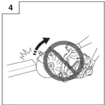

31 32 33
natural_image
Medical illustration showing a patient undergoing a medical procedure with a tool and device (no text or symbols)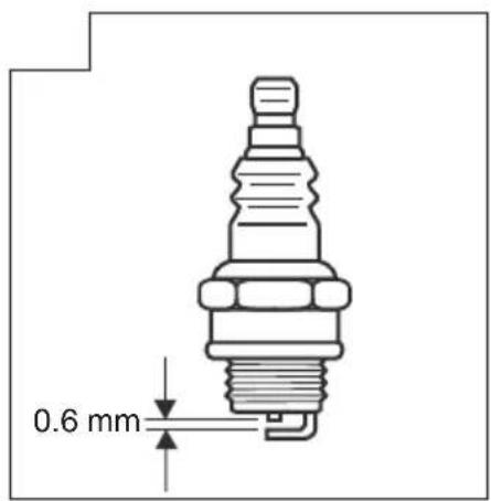
38 39
(Original instructions)
Pay special attention to statements preceded by the following words:

WARNING
Indicates a strong possibility of severe personal injury or loss of life if instructions are not followed.
CAUTION
Indicates a possibility of personal injury or equipment damage if instructions are not followed.
NOTE
Helpful information for correct function and use.
MEANINGS OF SYMBOLS
NOTE: Some units do not carry them.
 | Symbols⚠ WARNINGThe following show symbols used for the machine. Be sure that you understand their meaning before use. |
 | Cutter, Portable cut-off machineTCM75EAP / TCM75EBP |
 | It is important that you read, fully understand and observe the following safety precautions and warnings. Careless or improper use of the unit may cause serious or fatal injury. |
 | Read, understand and follow all warnings and instructions in this manual and on the unit. |
 | Always wear eye, head and ear protectors, and also dust protection, when using this unit |
 | Choke |
 | On / Start |
 | Off / Stop |
 | Emergency stop |
 | Maximum spindle speed of the machine. Warning: Do not use wheels that are rated for speeds lower than the indicated maximum spindle speed of the machine. |
 | Fire warning! This tool generates sparks when cutting metal. |
 | Warning! Do not use damaged cut-off wheel. |
 | Rotation direction of cut-off wheel |
 | Cut-off wheel dimensions |
 | Fuel and oil mixture |
 | Carburetor adjustment - Idle speed |
 | Carburetor adjustment - Low speed mixture |
 | Carburetor adjustment - High speed mixture |
| [XBT7] | Priming pump |
 | Guaranteed sound power level |
 | Decompression valve |
 | Hazardous dust and gas emission warning |
 | Kickback warning |
 | Warning! Never use blades designed for cutting wood. |
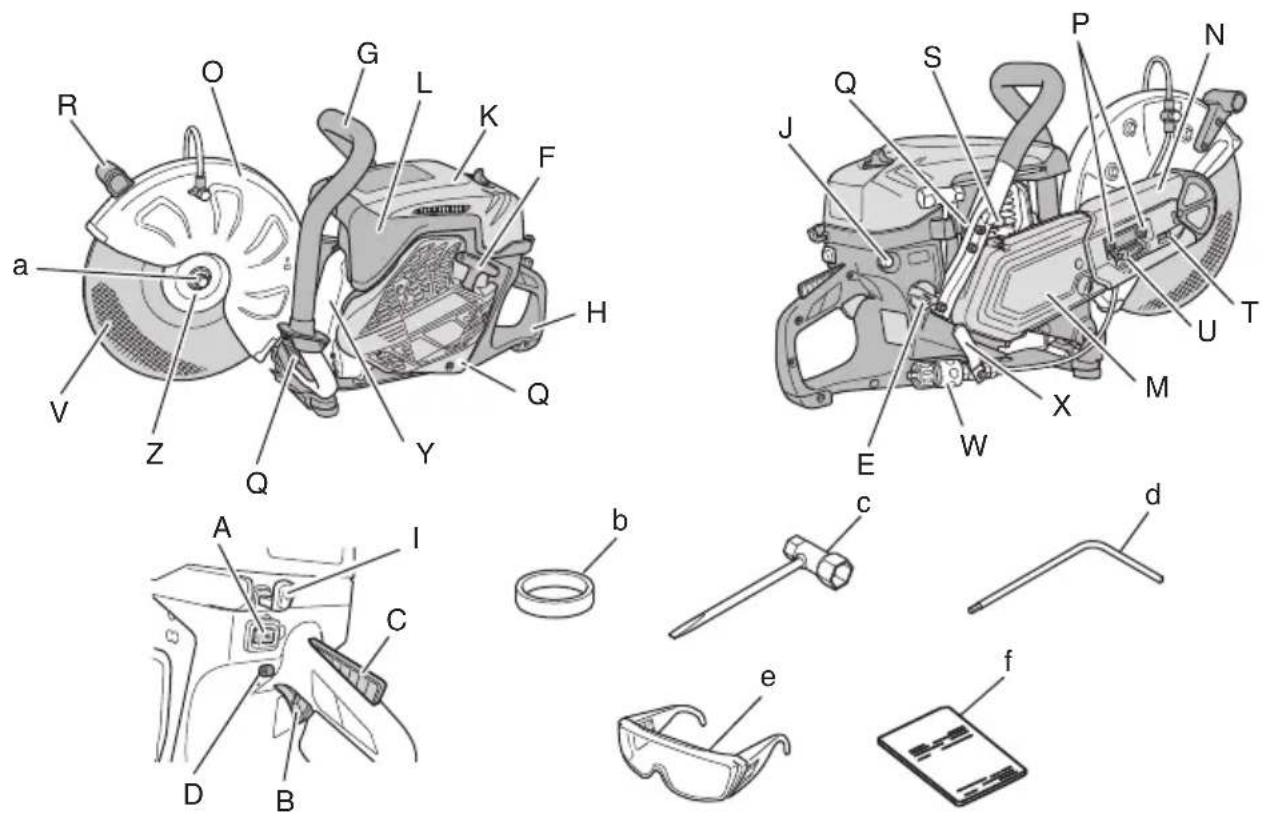
WHAT IS WHAT? (Fig. 1)
A: Stop switch: Device for allowing the engine to be started or stopped.
B: Throttle lever: Device activated by the operator's finger, for controlling the engine speed.
C: Throttle lever lockout: Device that prevents the accidental operation of the throttle lever until manually released.
D: Throttle lock: Device for setting the throttle in partially open position to aid starting.
E: Fuel tank cap: For closing the fuel tank.
F: Starter knob: Pull handle to start the engine.
G: Front handle: Support handle located at or towards the front of the engine housing.
H: Rear handle: Support handle located at or towards the rear of the engine housing.
I: Choke lever: Device for enriching the fuel/air mixture in the carburetor, to aid starting.
J: Priming pump: Device for supplying extra fuel, to aid starting.
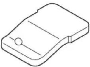
K: Cleaner box (B): Cover for pre-fi iter
L: Cleaner box (A): Cover for paper-fi iter and carburetor.
M: Clutch cover: Device between the engine and the cutting equipment designed to prevent unintentional contact with the transmission.
N: Arm cover: Device between the engine and the cutting equipment designed to prevent unintentional contact with the transmission.
O: Wheel guard: Cover which is intended to protect the operator from wheel contact, and also directs debris away from the operator.
P: Nut: Secures the wheel guard to engine.
English
Q: Anti-vibration spring: Reduce the transmission of vibrations to the operator's hands.
R: Handle(W): Handle for rotating the wheel guard.
S: Decompression valve: Device for reducing the compression pressure of engine to aid starting.
T: Tensioner bolt: Device to increase and release belt tension.
U: Tension nut: Mark for indicating the state of tension of the belt.
V: Cut-off wheel: Bonded abrasive with reinforced resinoid wheel for cutting, with blotter.
W: Coupler: Device for attaching the hose
X: Valve: Device for adjusting water flow rate.
Y: Muffler: Reduces engine exhaust noise and directs the exhaust gases.
Z: Wheel washer: Flange provided to clamp and drive the cut-off wheel.
a: Bolt: Secures the cut-off wheel
b: Adapter collar: Spindle attachment for using arbor hole 25.4mm cut-off wheels.
c: Combi box spanner: Maintenance tool for removing or installing a spark plug
d: Hex. wrench: Maintenance tool for removing cover and tensioning the belt.
e: Protective glasses: Eye protection.
f: Handling instructions: Included with unit. Read before operation and keep for future reference to learn proper, safe techniques.
WARNINGS AND SAFETY INSTRUCTIONS
Operator safety
○ Always wear a proper face shield or protective glasses.
☐ Gloves should always be worn when operating this machine and also when touching the cut-off wheel.
When using this machine, always wear proper protective attire such as jacket, trousers, helmet, boots with steel toe-caps and non-slip soles, and eye, ear, leg protection equipment whenever you use this machine.
Do not wear loose clothing, jewelry, short pants and/or sandals, or go barefoot.
Never let a child or inexperienced person operate the machine. A first-time operator should obtain practical instruction before using the machine.
When you wear hearing protection, pay attention to your surroundings. Be aware of any bystanders who may be signaling a problem.
○ Cutting operations can expose you to respiratory hazards such as silica and other harmful dust particles. Please wear a protective mask when operating this machine.
○ Keep handles free of oil and fuel.
○ Keep hands away from cutting equipment.
○ Do not grab or hold the machine by the cutting equipment.
○ Do not smoke or allow smoking near fuel or the machine, or while using the machine.
○ When the unit is shut off, make sure the cutting attachment has stopped before setting down the unit.
When operation is prolonged, take a break periodically so that you may avoid possible Hand-Arm Vibration Syndrome (HAVS) which is caused by vibration.
○ National regulation can restrict the use of machine. And the operator must obey the local regulations of working area.
WARNING
The machine produces exhaust fumes, which include hydrocarbons and benzene. When using this machine, sufficient ventilation is needed, not only if used indoors but also when working in trenches, hollows or other confined locations. Breathing exhaust fumes can be fatal.
☐ Do not operate this machine when you are tired, ill or under the influence of alcohol, drugs or medication.
○ Antivibration systems do not guarantee that you will not sustain Hand-Arm Vibration Syndrome or carpal tunnel syndrome.
Therefore, continual end regular users should monitor closely the condition of their hands and fingers. If any of the above symptoms appear, seek medical advice immediately.
○ Long or continuous exposure to high noise levels may cause permanent hearing impairment. Always wear approved hearing protection when operating a machine.
If you are using any medical electric / electronic devices such as a pacemaker, consult your physician as well as the device manufacturer prior to operating any power equipment.
Unit / machine safety
○ Inspect the entire machine for any damage before each use. Check for fuel leaks and make sure all fasteners are in place and securely tightened.
○ Keep others away when making carburetor adjustments.
○ Use only accessories as recommended for this machine by the manufacturer.
○ Select and mount the correct cut-off wheel for the type of work to be carried out.
All items, other than the items listed in the operator's / owner's manual, should be performed by Tanaka dealer. (For example, if improper tools are used to remove the flywheel or if an improper tool is used to hold the flywheel in order to remove the clutch, structural damage to the flywheel could occur and could subsequently cause the flywheel to burst.)
WARNING
☐ Never modify the machine in any way. Do not use your machine for any job except that for which it is intended.
☐ Never use wheels that are rated for speeds lower than the maximum spindle speed indicated on the machine. A wheel running faster than its rated speed can break and fly apart.
☐ The arbor size of wheels and flanges must properly fit the spindle of the machine.
Wheels and flanges with arbor holes that do not match the mounting hardware of the machine will run off - balance, vibrate excessively and may cause loss of control.
☐ It is important to use only cut-off wheels designed for use on hand-held cut-off machines. It is dangerous to use a cut-off wheel that is not intended for a hand-held cut-off machine.
Fuel safety
○ Mix and pour fuel outdoors and where there are no sparks or flames.
○ Use a container approved for fuel.
○ Wipe off all fuel spills and allow any remaining fuel to evaporate before starting engine.
○ Move at least 3 m away from fueling site before starting engine.
○ Stop engine and let it cool for a few minutes before opening fuel tank cap.
○ Store the machine and fuel in area where fuel vapors cannot reach sparks or open flames from water heaters, electric motors or switches, furnaces, etc.

WARNING
Fuel is highly fl ammable and its fumes should not be inhaled. Be particularly careful when handling the machine as the sparks produced when cutting metal can easily ignite any fuel spillage.
Cutting safety
Keep bystanders at a safe distance, away from the work area. Anyone entering the work area must wear personal protective equipment. Flying fragments from the workpiece or the cut-off wheel may cause injury. Children, other unauthorized persons and animals must remain well away from the work area.
○ Hold the machine firmly with the right hand on the rear handle and the left hand on the front handle.
○ Keep firm footing and balance. Do not over-reach.
Keep all parts of your body away from the muffler and cutting attachment when the engine is running.
○ Make sure to check the work area for any hidden hazards such as water or gas pipes, electrical cables and flammable substances.
○ Never place the machine on the ground when running.
○ Always ensure that the engine is shut off and any cutting attachments have completely stopped before clearing debris from the cutting attachment.
○ Always carry a first-aid kit when operating any power equipment.
☐ The muffler gets very hot during and after use. This also applies during idling.
Be aware of the fire hazard, especially when working near fl ammable substances and/or vapours.

WARNING
○ Exhaust gases from the engine are hot and may contain sparks which can cause a fire.
Also, sparks are generated when cutting metal with this machine.
Never use the machine where flammable substances and gases are present.
○ Sparks generated from cutting operations can cause fires. Always have adequate fire extinguishing equipment available.
When relocating to a new work area, be sure to shut off the machine and ensure that all cutting attachments are stopped.
○ Always ensure that the engine is shut off and any cutting attachments have completely stopped before moving.
Gyroscopic forces occur when moving while the engine is operating and the cut-off wheel is rotating. This may cause you to lose control of the machine.
○ Never cut materials that consist of asbestos.
○ Never leave the engine running while unattended (e.g. on the ground).
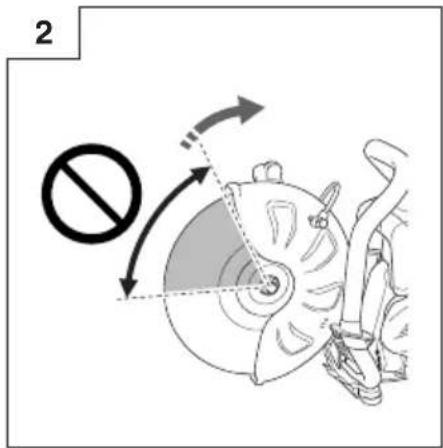
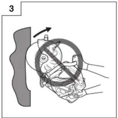
Kickback and related warnings
Kickback is a sudden reaction to a pinched or snagged rotating wheel. Pinching or snagging causes sudden stalling of the rotating wheel which in turn causes the machine to be forced in the direction opposite of the wheel's rotation at the point of the binding. For example, if an abrasive wheel is snagged or pinched by the workpiece, the edge of the wheel that is entering into the pinch point can dig into the surface of the material causing the wheel to climb out or kick out. The wheel may either jump toward or away from the operator, depending on the direction of the wheel's movement at the point of pinching. Abrasive wheels may also break under these conditions.
Either of these reactions may cause you to lose control of the machine which could result in serious personal injury.
Kickback is the result of cut-off machine misuse and/or incorrect operating procedures or conditions that can be avoided by taking proper precautions as given below.
○ Kickback occurs when the upper angle of the cut-off wheel is used or touches an object when the cut-off wheel is running. Pay special attention not to touch the upper angle of the cut-off wheel to any object. (Fig. 2, Fig. 3)
○ Use special care when working corners, sharp edges etc. Avoid bouncing and snagging the cut-off wheel.
Corners, sharp edges or bouncing have a tendency to snag the rotating wheel and cause loss of control or kickback. (Fig. 4)
Do not use cut-off wheels other than those approved or recommended by the manufacturer. Never use blades designed for cutting wood. Failure to comply could result in personal accidents or injury.
Do not jam the wheel or apply excessive pressure. Do not attempt to make an excessive depth of cut. Overstressing the wheel increases the loading and susceptibility to twisting or binding of the wheel in the cut and the possibility of kickback or wheel breakage.
If the wheel binds or a cut is interrupted for any reason, stop the engine and hold the machine motionless until the wheel comes to a complete stop. Never attempt to remove the wheel from the cut while the wheel is in motion otherwise kickback may occur. Investigate and take corrective action to eliminate the cause of wheel binding.
Do not restart the cutting operation with the wheel in the workpiece. After allowing the wheel to reach full speed, carefully re-enter the cut. The wheel may bind, walk up or kickback if the power tool is restarted in the workpiece.
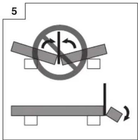
○ Provide supports for panels or any oversized workpiece to minimize risk of wheel pinching and kickback.
Large workpieces tend to sag under their own weight. Supports must be placed under the workpiece so that the cutting surface to open. (Fig. 5)
Maintenance safety
○ Maintain the machine according to recommended procedures.
○ Disconnect the spark plug before performing maintenance except for carburetor adjustments.
○ Keep others away when making carburetor adjustments.
○ Use only genuine Tanaka replacement parts as recommended by the manufacturer.
CAUTION
Do not disassemble the recoil starter. There is a possibility of personal injury with recoil spring.
WARNING
Improper maintenance could result in serious engine damage or in serious personal injury.
Transport and storage
○ Carry the machine by hand with the engine stopped and the muffler away from your body.
○ Allow the engine to cool, empty the fuel tank and carburetor, and secure the machine before storing or transporting.
○ Store machine out of the reach of children.
○ Clean and maintain the machine carefully and store it in a dry place.
○ Make sure stop switch is off when transporting or storing.
☐ Do not store the cut-off wheels in a wet or frost condition. Pay special attention about the abrasive wheel.
There is a risk of bursting to using the abrasive wheel wetted.
If situations occur which are not covered in this manual, take care and use common sense. Contact Tanaka dealer if you need assistance.
SPECIFICATIONS
| Model | TCM75EAP TCM75EBP | ||
| Engine displacement (cm3) 75.0 | |||
| Spark Plug NGK BPMR-7A | |||
| Max. engine power by ISO 7293 (kW) 3.9 | |||
| Rated engine speed by ISO 7293 (min-1) 9200 | |||
| Max. engine speed (min-1) 9800 | |||
| Idle engine speed (min-1) 2500 | |||
| Fuel Tank Capacity (L) 1.1 | |||
| Dry weight (kg) Without fuel, wheel and accessories | 10.4 10.6 | ||
| Abrasive wheel | Wheel type Type 41 | ||
| Outer diameter (mm) 305 (12") 355 (14") | |||
| Arbor hole diameter (mm) 20 (25.4 with Adapter collar) | |||
| Max. speed (min-1) 5100 or more | |||
| Max. Thickness (mm) 3.5 | 4.0 | ||
| Diamond wheel | Outer diameter (mm) 305 (12") 355 (14") | ||
| Arbor hole diameter (mm) 20 (25.4 with Adapter collar) | |||
| Max. speed (min-1) 5100 or more | |||
| Max. Thickness (mm) 3.5 | 4.0 | ||
| Minimum flange outside diameter (mm) | 101.7 | ||
| Wheel-fastener tightening torque (N·m) | 20 | ||
| Spindle diameter (mm) | 20 (25.4 with Adapter collar) | ||
| Spindle max. speed (min-1) | 4200 | ||
| Sound pressure level LpA*1(dB(A)) by ISO 19432 Measured / Uncertainty 99.5 / 3.0 | |||
| Sound power level LwA*2 (dB(A)) by ISO 19432 Measured / Uncertainty | 115 / 3.0 | ||
| Vibration level (m/s2) by ISO 19432 Front handle*1 / Rear handle*1 Uncertainty | 2.2 / 2.7 1.0 | 2.4 / 2.9 1.0 | |
NOTE
Noise level/vibration levels are calculated as the time-weighted energy total for noise / vibration levels under various working conditions with the following time distribution:
*1: 1/7 idle, 6/7 full load.
*2: Full load.
All data subject to change without notice.
ASSEMBLY PROCEDURES
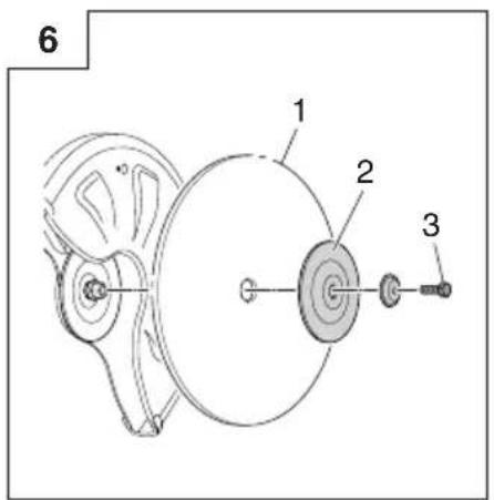
Assembly of cut-off wheel
- Place the wheel (1) between the two flanges (2), and tighten the bolt (3) by hand. (Fig. 6)
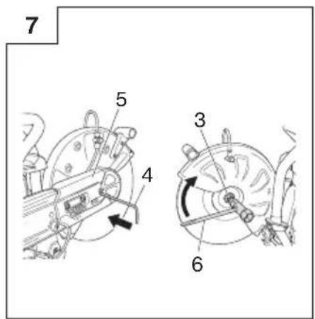
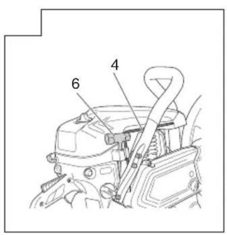
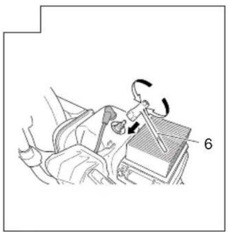
- Insert the hex. wrench (4) into the hole of arm cover (5) and lock the spindle in place while tightening the bolt (3) securely using the combi box spanner (6). (Fig. 7)
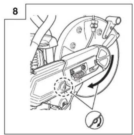
- Make sure the rotation direction of the diamond wheel conforms to the direction indicated on the clutch cover and install the diamond wheel. (Fig. 8)
NOTE
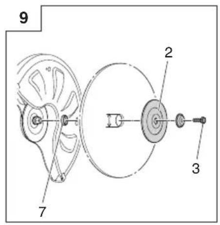
○ When using a wheel with an arbor hole of 25.4mm, securely attach the adapter collar (7) to the spindle. (Fig. 9)
○ Select and mount the correct cut-off wheel for the type of work to be carried out.
| Abrasive wheels | Diamond wheels | |
| Plastic | √ (Special wheel) | — |
| Masonry | √ | √ |
| Metal | √ | √ (Special wheels) |
| Cast iron | √ | √ (Special wheels) |
WARNING
☐ Do not use damaged wheels. Before each use, inspect the wheels for chips, cracks, distortion of shape or imbalance and reject any such wheel.
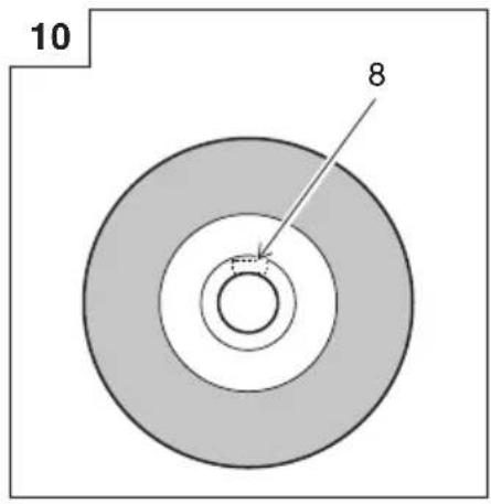
○ When you use the abrasive cut-off wheel check the expiration year marked (8) on the wheel before attaching. (Fig. 10)
There is a risk of bursting when using a wheel that it past its expiration year.
Before tightening the bolt, check that the direction of the two flanges is correct. Also check that the flanges are securely installed in the flats of the spindle.
☐ The correct tightening torque is 20 N·m. Do not tighten more than 20 N·m.
☐ Check the wheel by running it for 1 minutes at full throttle before applying it to a workpiece.
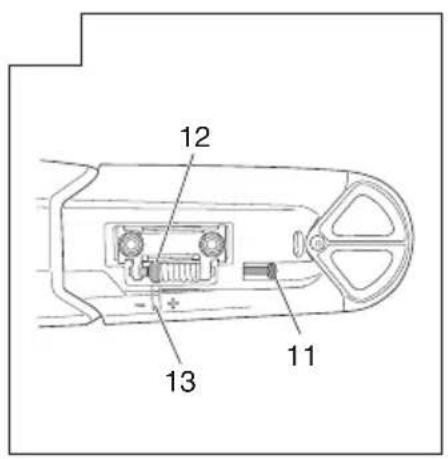
Adjustment of belt
- Loosen the nut (9) with the combi box spanner (6) so that the arm cover can (10) move. (Fig. 11)
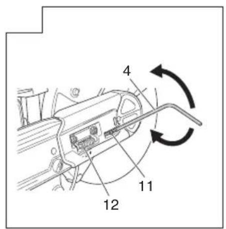
- Use the hex. wrench (4) to rotate the tensioner bolt (11) so that the position of the tension nut (12) matches with the marking (13) on the arm cover (10). (Fig. 12, Fig. 13)
- Tighten the nut again.
NOTE
Sufficient power is not transmitted to the wheel when the belt is loose. Appropriately adjust the belt as necessary.
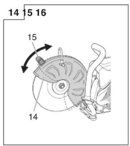
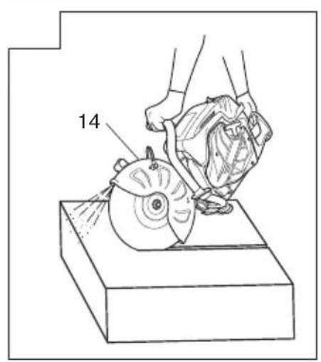
Adjustment of wheel guard
- Wheel guard (14) can be moved by hand without using a tool. To adjust the wheel guard (14), use handle(W) (15), or press the end of wheel guard (14) against the workpiece. (Fig. 14)
Make sure to adjust the wheel guard (14) to shield you from any flying debris. (Fig. 15)
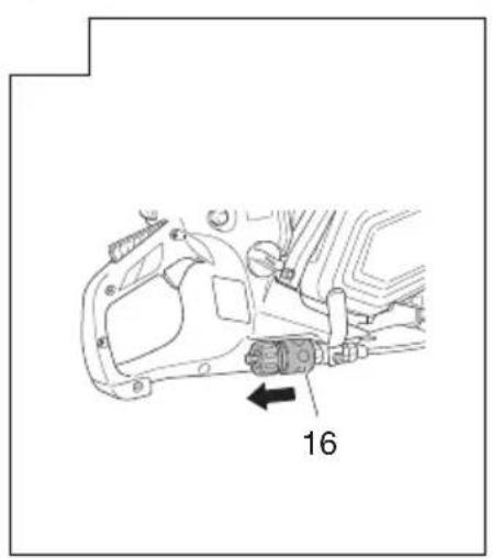
Wet cutting with water
This machine can be set up for wet cutting which can suppress dust emission during cutting.
- Remove coupler (16) by pulling the coupler from the machine. (Fig. 16)
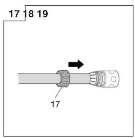
- Remove the ring (17) from the coupler, slide the ring over the hose and insert the hose to the coupler. (Fig. 17)
- Re-tighten the ring to the coupler securely.
- Reattach the coupler to the machine until it locks into position.
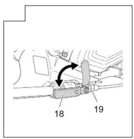
- Running water into the hose, turn the lever (18) of valve (19). (Fig. 18) This will supply to the cut-off wheel.

Warning
The cut-off wheel that is included with this machine is an abrasive cut-off wheel for concrete, stone, or masonry.
When cutting with water supplied to this cut-off wheel, use the wheel up on the same day. There is a risk of bursting when using the abrasive wheel wetted in this manner on the following day.
For other cut-off wheels, follow the instructions provided with those cut-off wheels.
Mounting the tools to the machine (Fig. 19)
This machine is designed to store the combi box spanner (6) and hex. wrench (4).
OPERATING PROCEDURES
Fuel

WARNING
☐ The machine is equipped with a two-stroke engine. Always run the engine on fuel, which is mixed with oil. Provide good ventilation, when fueling or handling fuel.
☐ Fuel is highly flammable and it is possible to get seriously injured when inhaling or spilling on your body.
Always pay attention when handling fuel. Always have good ventilation when handling fuel.
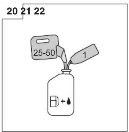
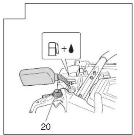
Fuel (Fig. 20)
○ Always use branded 89 octane unleaded gasoline.
○ Use genuine two-cycle oil or use a mix between 25:1 to 50:1, please consult about the oil mixture ratio to Tanaka dealer.
○ If genuine oil is not available, use an anti-oxidant added quality oil expressly labeled for air-cooled 2-cycle engine use (JASO FC GRADE OIL or ISO EGC GRADE). Do not use BIA or TCW (2-stroke water-cooling type) mixed oil.
○ Never use multi-grade oil (10 W/30) or waste oil.
Never mix fuel and oil in machine's fuel tank. Always mix fuel and oil in a separate clean container.
Fuel mixing method
Always start by filling half the amount of gasoline, which is to be used into container.
Then add the whole amount of oil. Mix (shake) the fuel mixture. Add the remaining amount of gasoline.
Mix (shake) the fuel-mix thoroughly before filling the fuel tank.
Mixing amount of two-cycle oil and gasoline
| Gasoline (Liter) | Two-cycle oil (ml) | |
| Ratio 50:1 Ratio 25:1 | ||
| 0.5 10 | — | 20 |
| 1 20 | — | 40 |
| 2 40 | — | 80 |
| 4 80 | — | 160 |
Fueling (Fig. 21)
Before fueling, clean fuel tank cap (20) area carefully to ensure that no dirt falls into the tank. Make sure that the fuel is well mixed by shaking the container before adding fuel.

WARNING
○ Always shut off the engine and let it cool for a few minutes before refueling.
Do not smoke or bring fl ames or sparks near the fuel.
○ Slowly open the fuel tank cap (20), when filling up with fuel, so that possible overpressure disappears.
○ Tighten the fuel tank cap carefully, after fueling.
○ Always move the unit at least 3 m from the fueling area before starting.
○ Always wash any spilled fuel from clothing immediately with soap.
○ Be sure to check any fuel leaking after refueling.
Before fueling, in order to remove static electricity from the main body, the fuel container and the operator, please touch the ground that is slightly damp.
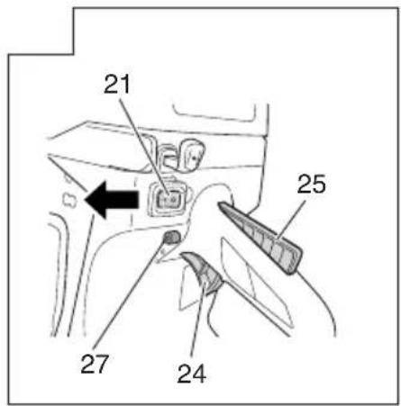
Starting the cold engine (Fig. 22-27)
CAUTION
Before starting, make sure that the cut-off wheel does not touch anything.
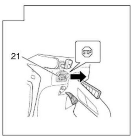
- Set stop switch (21) to ON position. (Fig. 22)
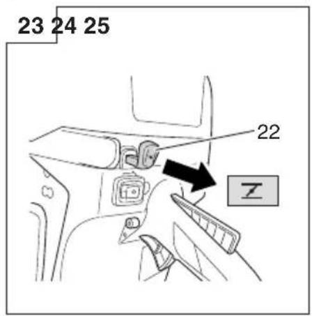
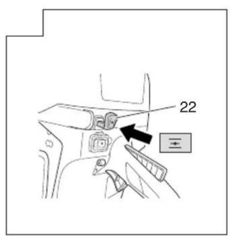
- Pull choke lever (22) fully to set it in the START position. (Fig. 23)
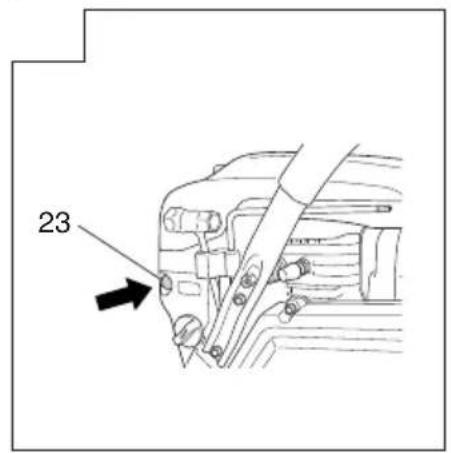
- Push the priming pump (23) approximately ten times so that fuel flows into carburetor. (Fig. 24)
- Fully pull the throttle lever (24) while pressing the throttle lever lockout (25). Then press the throttle lock (27). This will automatically lock to half throttle, to aid in starting the engine. (Fig. 22)
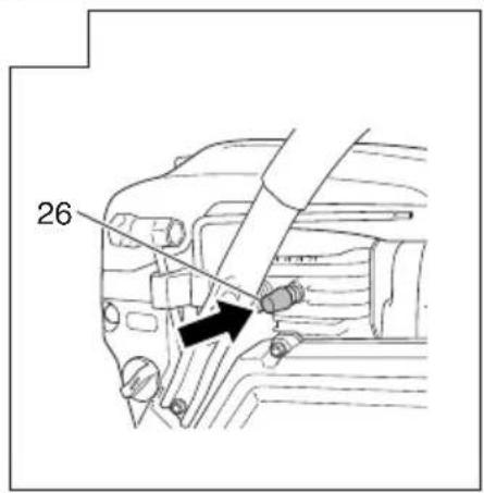
- Push the decompression valve (26). The valve will automatically return to the original position once the engine has started. (Fig. 25)
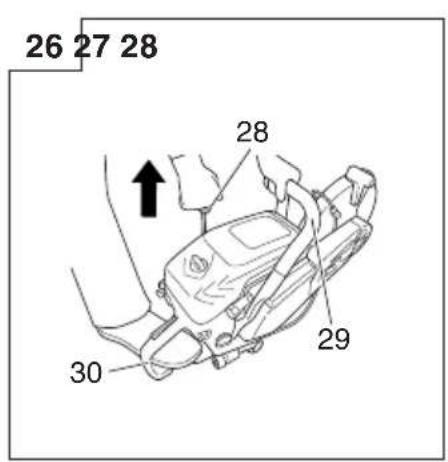
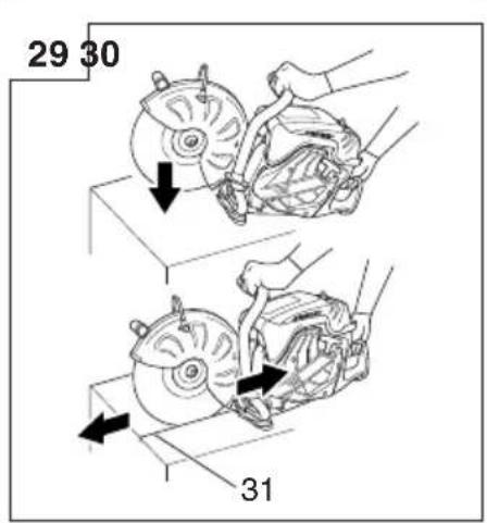
- Holding the tool in position with the left hand on the front handle (29) and the right foot pressing down on the rear handle (30), rapidly pull the starter knob (28). (Fig. 26)
- When you hear first ignition, push the choke lever (22) fully to set it in the run position. (Fig. 27)
- Push decompression valve (26) again.
- Pull starter knob (28) rapidly again in the aforementioned manner.
- As soon as the engine starts, pull throttle lever (24) full once with throttle lever lockout (25) pressed and immediately release throttle lock (27). Then half throttle is disengaged.
- Allow the engine to warm up for about 2 to 3 minutes before cutting.
NOTE
To avoid reducing engine life, do not run the engine at high speeds without any load over a long period of time.
Starting the warm engine
Use only 1, 5, and 6 of the starting procedure for a cold engine.
If the engine does not start, use the same starting procedure as for a cold engine.
English
Stopping (Fig. 28)
Decrease engine speed, and push stop switch (21) to stop position.

WARNING
Do not put the machine where there are flammable materials such as dried grass, since the muffler is still hot after the engine has stopped.
Basic cutting techniques
-
Adjust the wheel guard to shield you from flying debris.
-
Cut a straight shallow line (31) to the range to be cut. (Fig. 29)
-
Cut straight along the line to the required depth.

WARNING
○ Do not overreach or cut above shoulder height.
○ Operator and bystanders must not stand in the line of rotation of the cut-off wheel. Doing so may result in serious injury or death should the wheel burst.
☐ Never apply lateral pressure (side force) to the cut-off wheel during cutting. Doing so will damage the cut-off wheel.
○ Do not cut in a curved line.
NOTE
When cutting, move the machine back and forward along the line in order to be not overheat the cut-off wheel. If you cut the same position in long time, the cut-off wheel may get hot and be weakened.
○ Always cut at full speed at all times with pressing lightly. This is the way to get best efficient for cutting.
☐ Do not cut a deep groove at one time. To make deep groove, cut several times a shallow groove.
MAINTENANCE
Carburetor adjustment
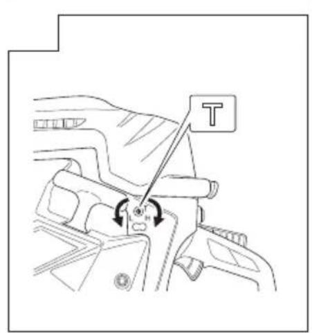
In the carburetor, fuel is mixed with air. When the engine is test run at the factory, the carburetor is adjusted. A further adjustment may be required, according to climate and altitude. The carburetor has one adjustment possibility: T = Idle speed adjustment screw.
Idle speed adjustment (T) (Fig. 30)
Check that the pre-filter and paper filter are clean. When the idle speed is correct, the cutting attachment will not rotate. If adjustment is required, close (clockwise) the T-screw, with the engine running, until the cutting attachment starts to rotate. Open (counter-clockwise) the screw until the cutting attachment stops. You have reached the correct idle speed when the engine runs smoothly in all positions well below the rpm when the cutting attachment starts to rotate.
If the cutting attachment still rotates after idle speed adjustment, contact Tanaka dealer.

WARNING
When the engine is idling, the cutting attachment must not rotate under any circumstances.
NOTE
- Please use combi box spanner for adjusting the T-screw. - Do not touch the High speed adjustment (H) and the Low speed adjustment (L) screws on the carburetor. Those are only for Tanaka dealer. If you rotate them, it will cause a serious damage to the machine.
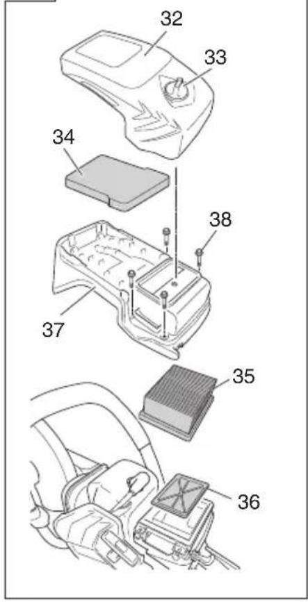
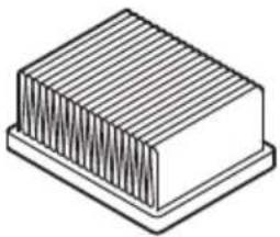
Air fi Iter (Fig. 31)
If the engine power seems to have decreased, it is likely because the air filter needs to be cleaned.
- Before cleaning the air filter, pull the choke lever (22) to prevent dust from entering into the engine.
-
Open cleaner box (B) (32) by loosening cleaner knob (33) to expose the pre-filter (sponge form) (34) inside the cleaner box (B) (32).
-
Clean the pre-filter by tapping or blowing it gently. If the pre-filter is still dirty, rinse it in warm soap suds.
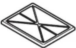
If the inside of cleaner box (B) (32) that is closed off by the pre-filter is dirty with dust, clean the paper-filter (35) in the following manner. - In order to take out of paper-filter (35) and nylon-filter (36), open the cleaner box (A) (37) by loosening the M5 set bolt (38).
- Clean the nylon-filter by tapping or blowing it gently. If the nylon-fi liter is still dirty, rinse it in warm soap suds.
- Clean the paper-filter by tapping. If you use compressed air to blow out the dust, apply the air gently from inside.
- Reassemble the parts to their original positions by following the aforementioned steps in reverse.
NOTE
When you remove paper-filter and nylon-filter, please take care so that dust does not get inside the engine.
○ After rinsing in warm soap suds. Check to make sure that the filter is dry before reassembly. An air filter that has been used for some time cannot be cleaned completely. Therefore, it must regularly be replaced with a new one. A damaged filter must always be replaced.
Spark plug (Fig. 31, 32, 33)
-
Remove cleaner box (B) (32) and cleaner box (A) (37). (Fig. 31)
-
Remove the spark plug by turning it counterclockwise with the combi box spanner. (Fig. 32)
-
Clean the spark plug if it is dirty. Check the electrode gap. The correct gap is 0.6 mm. (Fig. 33)
NOTE
○ When you remove the spark plug, please take care so that dust does not get inside the engine.
☐ The spark plug should be replaced after about 100 operation hours or earlier if the electrodes are badly eroded.
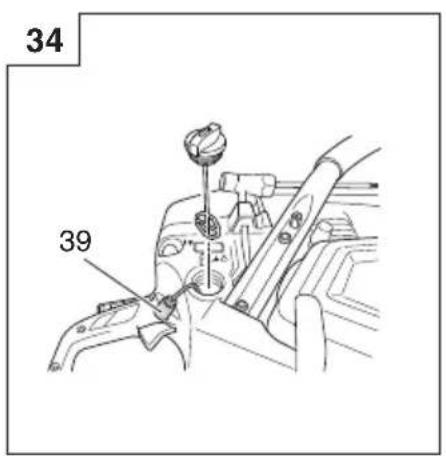
Fuel fi Iter (Fig. 34)
Remove the fuel filter (39) from the fuel tank and thoroughly wash it in solvent. After that, push the fuel filter into the tank completely.
NOTE
If the fuel filter (39) is hard due to dust and dirt, it must be replaced.
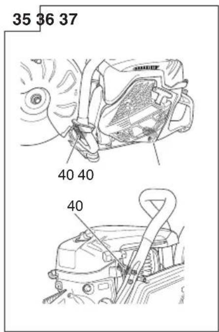
Anti-vibration systems (Fig. 35)
Check the springs (40) for any loosening or damage. If you find any failure in those parts, please contact a Tanaka dealer.
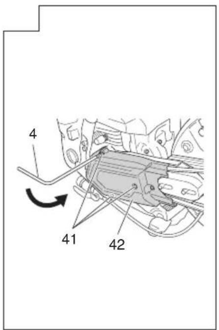
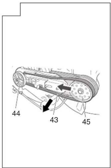
Replacing of belt
- Remove nut (9) using the combi box spanner (6) and loosen the tensioner bolt (11) by rotating it counterclockwise with the hex. wrench (4). Then, remove the arm cover (10). (Fig. 11, 12)
- Loosen the three bolts (41) on the clutch cover (42) and remove clutch cover (42). (Fig. 36)
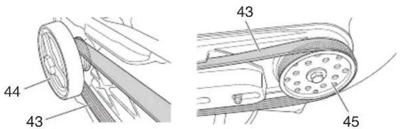
- Remove the belt (43) and set a new one in the grooves of the pulleys (44)(45) securely. (Fig. 37, 38)
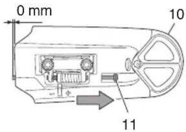
- Before assembling, turn the tensioner bolt (11) and adjust the length protrusion of the tensioner bolt (11) from the arm cover (10) to 0 mm. (Fig. 39)
- Assemble clutch cover and arm cover by following the aforementioned steps in reverse.
- Readjust the tension of the belt. Please refer to "Adjustment of belt".
Maintenance schedule
Daily maintenance
○ Clean the exterior of the machine.
○ Check that the nut on the arm cover is sufficiently tightened.
○ Check that the bolts for the cut-off wheel are sufficiently tightened.
○ Check that the cut-off wheel does not rotate when the engine is idling
○ Clean the air filter.
Weekly maintenance
○ Check the recoil starter, especially rope.
○ Clean the exterior of the spark plug.
○ Remove the spark plug and check the electrode gap. Adjust it to 0.6 mm or change the spark plug.
○ Check that the air intake at the recoil starter is not clogged.
Monthly maintenance
○ Rinse the fuel tank with gasoline, and clean fuel filter.
○ Clean the exterior of the carburetor and the space around it.
Quarterly maintenance
○ Clean the cooling fins on the cylinder.
○ Clean the fan and the space around it.
○ Clean the carbon of muffler.
CAUTION
Cleaning of cylinder fins, fan and muffler shall be done by Tanaka dealer.
TROUBLESHOOTING
| Condition Probable Cause | Remedy | |
| Engine does not start | No fuel or low fuel Supply fuel | |
| Fuel is not in the carburetor | Supply fuel and push priming pump a few times. | |
| Old fuel Supply new fuel | ||
| Spark plug is wet | 1. Remove spark plug and dry it2. Pull starter and dry the fuel inside the engine | |
| The fuel pipe is bent or detached Consult a Tanaka dealer | ||
| Carburetor failure Consult a Tanaka dealer | ||
| Spark plug failure Replace spark plug or correct the gap | ||
| Electrical system failure Consult a Tanaka dealer | ||
| Engine starts but immediately stalls | No fuel or low fuel Supply fuel | |
| Fuel is not in the carburetor | Supply fuel and push priming pump a few times. | |
| The choke is closed | Push choke lever securely | |
| Carburetor failure Consult a Tanaka dealer | ||
| Spark plug failure Replace spark plug or correct the gap | ||
| Clogged air filter | Clean the air filter | |
| Abnormal vibration | Faulty mounting of the cut-off wheel | Please refer to “Assembly of cut-off wheel” |
| Deformation of the cut-off wheel | Replace the cut-off wheel | |
| Anti-vibration system failure | Consult a Tanaka dealer | |
| Engine starts, but the cut-off wheel does not rotate | Belt is loose | Please refer to “Adjustment of belt” |
| Belt is too tight | ||
| Belt is out of pulleys | Please refer to “Replacing of belt” | |
| Engine does not stop | Electrical system failure Consult a Tanaka dealer | |
REPLACEMENT PARTS
 |  |  |  |
| 6699872 | 6699868 | 6699867 | 6699877 |
Deutsch
WAARSCHUWINGEN EN VEILIGHEIDSINSTRUCTIES
*1: 1/7 stationair, 6/7 volledige belasting.
*2: Volledige belasting.
HVAD ER HVAD? (Fig. 1)
*1: 1/7 tomgang, 6/7 full last.
*2: Full last.
Alle data kan endres uten varsel.
MONTERING
UPOZORENJA I BEZBEDNOSNA UPUTSTVA
UPOZORENJA I SIGURNOSNE UPUTE
Sigurnost korisnika
○ Uvijek nosite štit za lice ili zaštitne naočale.
○ Rukavice uvijek treba nositi prilikom rada sa strojem također pri dodirivanju rezača.
○ Pri korištenju ovog uređaja uvijek nosite pravilnu zaštitnu odjeću kao što su jakne, hlače, kacige, čizme s čeličnim umetkom na prstima i potplatima protiv klizanja, te zaštitu za oči, sluh i zaštitu za noge kad god koristite ovaj uređaj. Ne nosite široku odjeću, nakit, kratke hlače i/ili sandale i ni u kom slučaju ne koristite dok ste bosi.
○ Nikada ne dopustite djetetu ili neiskusnoj osobi da upravlja uređajem.
Prije prve uporabe uređaja, operater treba dobiti praktične instrukcije.
Kada nosite zaštitu za uši, obratite pozornost na vaše okruženje. Budite svjesni osoba koje vam mogu ukazati na problem.
○ Rezanje vas može izložiti opasnim tvarima za dišne puteve kao što su silikon i druge štetne čestice prašine. Molimo nosite zaštitnu masku prilikom rada s ovim uređajem.
○ Ručke moraju biti čiste i bez ulja i goriva.
○ Ruke držite podalje od opreme za rezanje.
○ Ne hvatajte i ne držite uređaj za opremu za rezanje.
○ Nemojte pušiti ili dopuštati pušenje u blizini goriva ili uređaja ili tijekom korištenja uređaja.
Kada je uređaj isključen, provjerite da se nastavak za rezanje zaustavio prije odlaganja uređaja.
○ Prilikom produženog rada, povremeno napravite pauzu, kako biste izbjegli nastanak sindroma vibracije šake i ruke (HAVS) uzrokovanog vibracijama.
○ Nacionalni propisi mogu ograničiti korištenje stroja.
Korisnik mora poštivati lokalne propise o radnom okruženju.
⚠ UPOZORENJE
○ Uređaj proizvodi ispušne plinove koji uključuju ugljikovodike i benzen. Kada koristite ovaj uređaj potrebna je dovoljna ventilacija, ne samo ako se koristi u zatvorenom prostoru, nego i kada se radi u jarcima, udubljenjima ili drugih skučenim mjestima. Udisanje ispušnih plinova može biti kobno.


- (Original instructions)
- WARNING
- CAUTION
- NOTE
- MEANINGS OF SYMBOLS
- WHAT IS WHAT? (Fig. 1)
- English
- WARNINGS AND SAFETY INSTRUCTIONS
- Operator safety
- Unit / machine safety
- Fuel safety
- Cutting safety
- Kickback and related warnings
- Maintenance safety
- Transport and storage
- ASSEMBLY PROCEDURES
- Assembly of cut-off wheel
- Adjustment of belt
- Adjustment of wheel guard
- Wet cutting with water
- Mounting the tools to the machine (Fig. 19)
- OPERATING PROCEDURES
- Fuel
- Fuel (Fig. 20)
- Fuel mixing method
- Fueling (Fig. 21)
- Starting the cold engine (Fig. 22-27)
- Starting the warm engine
- Stopping (Fig. 28)
- Basic cutting techniques
- MAINTENANCE
- Carburetor adjustment
- Idle speed adjustment (T) (Fig. 30)
- Air fi Iter (Fig. 31)
- Spark plug (Fig. 31, 32, 33)
- Fuel fi Iter (Fig. 34)
- Anti-vibration systems (Fig. 35)
- Replacing of belt
- Maintenance schedule
- Daily maintenance
- Weekly maintenance
- Monthly maintenance
- Quarterly maintenance
- Deutsch
- WAARSCHUWINGEN EN VEILIGHEIDSINSTRUCTIES
- HVAD ER HVAD? (Fig. 1)
- MONTERING
- UPOZORENJA I BEZBEDNOSNA UPUTSTVA
- UPOZORENJA I SIGURNOSNE UPUTE
- Sigurnost korisnika
- ⚠ UPOZORENJE
Brand : HiKOKI
Model : TCM75EAP
Category : String Trimmer