
HES 200 - Welding machine Herkules - Free user manual and instructions
Find the device manual for free HES 200 Herkules in PDF.
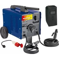



| Product Type | Electric Welding Machine |
| Brand | Herkules |
| Model | HES 200 |
| Supply Voltage | 230/400 V ~ 50 Hz (single-phase/three-phase) |
| Welding Current | 60 - 200 A |
| Open Circuit Voltage | 48 V |
| Duty Cycle (X%) | 5% at 200 A (400 V), 7% at 160 A (400/230 V), 15% at 115 A, 30% at 80 A, 60% at 60 A (230 V) |
| Electrode Diameter | 2.5 - 4 mm |
| Protection Rating | IP21S |
| Insulation Class | H |
| Thermal Protection | Yes (control lamp) |
| Weight | Approximately 35 kg |
| Included Accessories | Electrode holder, ground clamp, 230 V adapter cable, welding screen, instruction manual |
| Main Features | Arc welding with coated electrodes, continuous current adjustment, 230/400 V selector |
| Safety | Protection against electric shocks, fumes, sparks, UV rays, electromagnetic fields |
| Maintenance and Cleaning | Clean with a damp cloth and soap, do not use detergent, avoid water ingress |
| Spare Parts | Electrode holder, ground clamp |
| Warranty | 60 months |
Frequently Asked Questions - HES 200 Herkules
User questions about HES 200 Herkules
0 question about this device. Answer the ones you know or ask your own.
Ask a new question about this device
Download the instructions for your Welding machine in PDF format for free! Find your manual HES 200 - Herkules and take your electronic device back in hand. On this page are published all the documents necessary for the use of your device. HES 200 by Herkules.
USER MANUAL HES 200 Herkules
GB Original operating instructions Electric welder
RS Original instructions for use Electric arc welding device
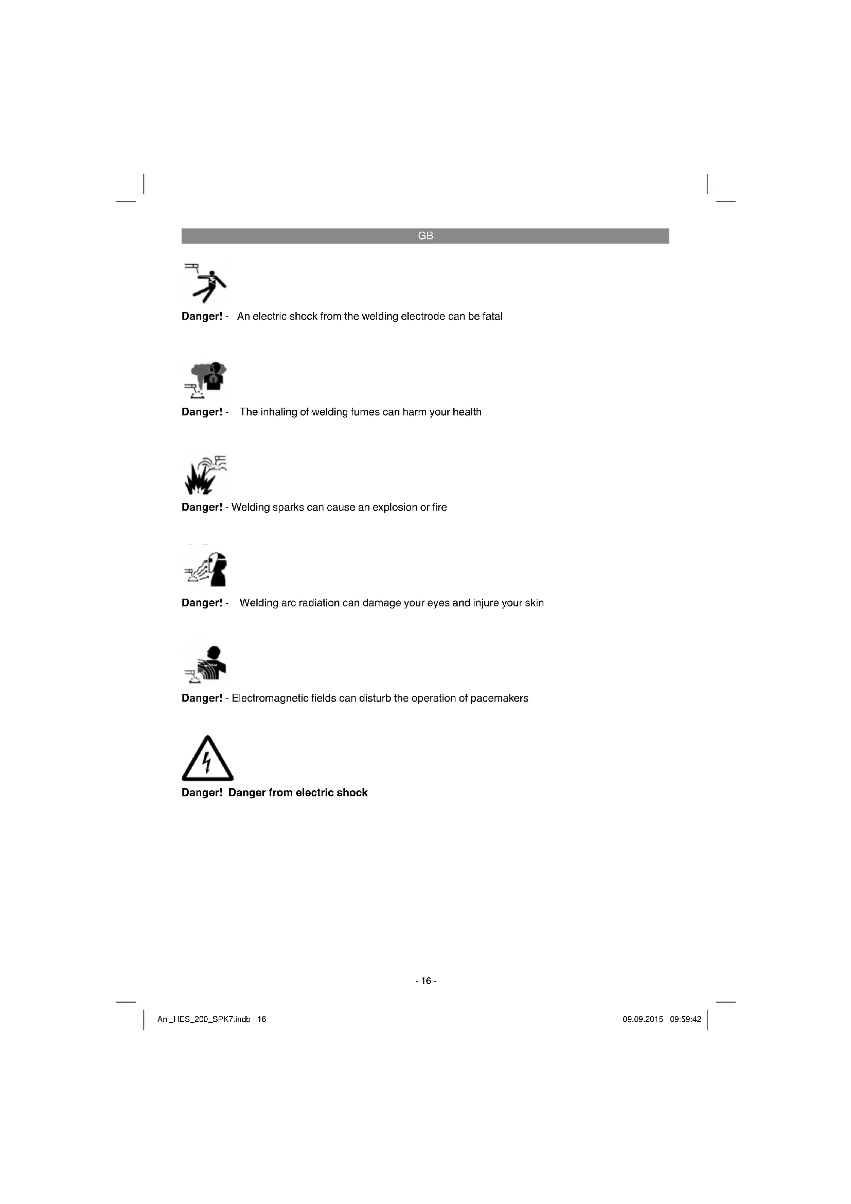
Danger! - An electric shock from the welding electrode can be fatal

Danger! - The inhaling of welding fumes can harm your health

Danger! - Welding sparks can cause an explosion or fire

Danger! - Welding arc radiation can damage your eyes and injure your skin

Danger! - Electromagnetic fields can disturb the operation of pacemakers
Danger! Danger from electric shock
GB
Danger!
When using the equipment, a few safety precautions must be observed to avoid injuries and damage. Please read the complete operating instructions and safety regulations with due care. Keep this manual in a safe place, so that the information is available at all times. If you give the equipment to any other person, hand over these operating instructions and safety regulations as well. We cannot accept any liability for damage or accidents which arise due to a failure to follow these instructions and the safety instructions.
1. Safety regulations
The corresponding safety information can be found in the enclosed booklet.
Danger!
Read all safety regulations and instructions. Any errors made in following the safety regulations and instructions may result in an electric shock, fire and/or serious injury.
Keep all safety regulations and instructions in a safe place for future use.
Safety components:
a) Danger from electric shock: An electric shock from a welding electrode can be fatal. Never perform any welding in rain or snow. Wear dry insulating gloves. Do not touch the electrode with your bare hands. Do not wear wet or damaged gloves. Protect yourself from an electric shock by insulating yourself from the workpiece. Do not open the equipment housing. b) Danger from welding fumes: The inhaling of welding fumes can harm your health. Keep your head out of the fumes. Use the equipment in open areas. Use a ventilation system to remove the fumes. c) Danger from welding sparks: Welding sparks can cause an explosion or fire. Keep combustible materials away from the welding area. Do not weld combustible materials. Welding sparks can cause fires. Keep a fire extinguisher nearby and someone watching who can use it immediately. Do not weld on drums or any closed containers. d) Danger from welding arc radiation: Welding arc radiation can damage your eyes and injure your skin. Wear a hat and safety goggles. Wear ear protection and a high, closed shirt collar. Use a welding helmet and filters of
the correct size. Wear complete body protection.
e) Danger from electromagnetic fields: Welding current creates electromagnetic fields. Do not use together with medical implants. Never wind the welding cables around your body. Guide welding cables together.
2. Layout and items supplied
2.1 Layout (Fig. 1)
- Electrode holder
- Earth terminal
- Adjustment wheel for welding current
- Selector switch 230V / 400V
- Control lamp for overheating
- Operating control lamp
- Welding current scale
- Carry handle 9. Wheels
- 400 V mains cable
- Supporting foot
- Adapter cable
- Welding screen
2.2 Items supplied
Please check that the article is complete as specified in the scope of delivery. If parts are missing, please contact our service center or the sales outlet where you made your purchase at the latest within 5 working days after purchasing the product and upon presentation of a valid bill of purchase. Also, refer to the warranty table in the service information at the end of the operating instructions.
- Open the packaging and take out the equipment with care.
- Remove the packaging material and any packaging and/or transportation braces (if available).
- Check to see if all items are supplied.
- Inspect the equipment and accessories for transport damage. If possible, please keep the packaging until the end of the guarantee period.
Danger!
The equipment and packaging material are not toys. Do not let children play with plastic bags, foils or small parts. There is a danger of swallowing or suffocating!
GB
Welding set - Carry handle (8) Wheels (9) Supporting foot (11) - Adapter cable (12) Fastening material (a-s) - Original operating instructions - Safety instructions
3. Proper use
The electric welder can be used to weld various metals using the appropriate coated electrodes.
The machine is to be used only for its prescribed purpose. Any other use is deemed to be a case of misuse. The user / operator and not the manufacturer will be liable for any damage or injuries of any kind caused as a result of this.
Important information about the power connection
This equipment falls under Class A of the standard EN 60974-10, i.e. it is not designed for use in residential areas in which the power supply is based on a public low-voltage supply system because given unfavorable conditions in the power supply the equipment may cause interference. If you want to use the equipment in residential areas in the which the power supply is based on a public low-voltage supply system, you must use an electromagnetic filter which reduces the electromagnetic interference to the point where the user no longer notices any disturbance.
In industrial parks or other areas in which the power supply is not based on a public low-voltage supply system the equipment can be used without such a filter.
General safety information
It is the user's responsibility to install and use the equipment properly in accordance with the instructions issued by the manufacturer. If electromagnetic interference is noticed, it is the user's responsibility to eliminate said interference with the technical devices mentioned in the section "Important information about the power connection".
Reduction of emissions
Main current supply
The welder must be connected to the main current supply in accordance with the instructions issued by the manufacturer. If interference occurs, it may be necessary to introduce additional measures, e.g. fitting a filter to the main current supply (see above in the section "Important information about the power connection"). The welding cables should be kept as short as possible.
Pacemakers
Persons using an electronic life support device (e.g. a pacemaker) should consult their doctor before they go near electric sparking, cutting, burning or spot-welding equipment in order to be sure that the combination of magnetic fields and high electric currents does not affect their devices.
For commercial users the guarantee period is 12 months and for normal users 24 months, beginning from the date of purchase.
4. Symbols and technical data
EN 60974-1
European standard for arc welding sets and welding power supplies with limited on time (Part 6).

Symbol for welding power supplies which are suitable for welding in environments with increased electrical danger.
~50Hz
Alternating current and rated frequency value [Hz]
U
Rated idling voltage [V]
200A/28V
Maximum welding current and the corresponding standardized operating voltage [A/V]
0
Electrode diameter [mm]
U
Welding voltage [V]
1
Welding current [A]
GB

3~50Hz
Line input; number of phases, the alternating current symbol and the rated frequency value
U,
Line voltage [V]
1max
Highest rated value of the line current [A]
1
Effective value of the highest line current [A]
IP 21S
Protection type
H
Insulation class
X
On-load factor
Mains connection: 230/400 V ~ 50 Hz
Welding current: 60 - 200 A
On-load factor X:
5% 200A (400V)
7% 160 A (400V/230V)
15% 115A (400V/230V)
30% 80A (400V/230V)
60% 60 A (230 V)
Idling voltage (V): 48
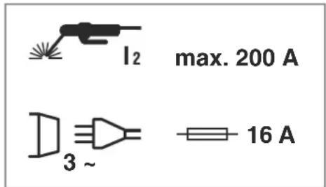
Power input: 8.8 kVA at 200 A
Fuse (A): 16
The welding times apply for an ambient temperature of 40°C
5. Assembly Instructions
See Figure 2, 10-20.
5.1 Installation of the welding screen (13)
- Place the welding glass (I) and the transparent safety glass (m) over it in the frame for the safety glass (k) (Fig. 3).
- Press the safety glass retaining pins (q) into the holes in the welding screen frame (s) from the outside. (Fig. 4)
- Place the frame for the safety glass (k) with the welding glass (l) and transparent safety glass (m) from the inside into the recess in the welding frame (s), press the safety glass
retaining bushes (n) onto the safety glass retaining pins (q) until they engage to secure the frame for the safety glass (k). The transparent safety glass (m) must be on the outside. (Fig. 5)
Bend the top of the welding screen frame (s) inwards (Fig. 6/1) and fold down the top corners (Fig. 6/2). Now bend the outer sides of the welding screen frame (s) inwards (Fig. 6/3) and connect them by pressing the top corners and outer sides together. As the retaining pins engage, you should be able to hear two clear clicks on each side (Fig. 6/4). - When the top corners of the welding screen are connected as shown in Figure 7, place the screws for the handle (p) from the outside through the three holes in the welding screen. (Fig. 8) - Turn over the welding screen and place the handle (r) over the threads on the three screws for the handle (p). Secure the handle (r) to the welding screen with the three nuts for the handle (o) (Fig. 9).
6. Power supply
This welding set can be operated with a rated voltage of 230 V and 400 V. The desired rated voltage can be set by means of the rotary switch (4). Please follow the operating instructions, as described below:
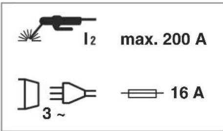
Please observe the following instructions in order to avoid the risk of fire, electric shock or personal injuries.
- Never use the appliance with a rated voltage of 400 V if the appliance is set to 230 V. Caution: Fire risk! Please disconnect the appliance from the power supply before setting the rated voltage. Adjusting the rated voltage during operation of the welding set is strictly prohibited.
Before operating the welding set, please ensure that the rated voltage selected on the appliance complies with that of the power source.
Note:
The welding unit is equipped with a 400 V ~ 16 A CeCon plug. Use the supplied adapter cable No. 12 to operate the welding unit with 230 V ~
7. Welding preparations
Connect the earth terminal (-) (2) directly to the part to be welded or to the support on which the part is resting. Ensure that the earth terminal (-) is in direct contact with the part to be welded. You should therefore avoid coated surfaces and/or insulated materials. The electrode holder cable has a special clamp at one end, which is used to secure the electrode. The welding safety shield must be used at all times for welding. It protects your eyes from the radiation emitted by the arc and nevertheless enables you to watch the welding process (not included in items supplied).
8. Welding
After you have made all the electrical connections for the power supply and for the welding circuit, you can proceed as follows: Insert the unsheathed end of the electrode into the electrode holder (1) and connect the earth terminal (-) (2) to the part you wish to weld. Ensure that a good electric contact is made. Switch on the welding set at the switch (4) and set the welding current using the hand wheel (3) to suit the electrode you wish to use. Hold the safety shield in front of your face and rub the tip of the electrode on the part you wish to weld as if you were striking a match. This is the best method of igniting the arc. Check that you have the correct electrode and current strength on a test part.
| Electrode (Ø mm): | |
| 2. | 40-80 A |
| 2.5 | 60 - 110 A |
| 3.2 | 80 - 160 A |
| 4 | 120 - 200 A |
Important!
Do not dab the workpiece with the electrode since it could be damaged, making it more difficult to ignite the arc.
As soon as the arc has ignited, attempt to keep it a distance from the workpiece equivalent to the diameter of the electrode.
This distance should be kept as constant as possible during the welding process. The angle of the electrode in the direction in which you are working should be 20 / 30°
Always use tongs to remove spent electrodes and to move parts that you have just welded. Please note that the electrode holder (1) must always be put down so that it is insulated after you have completed the welding work.
Do not remove the slag until the weld has cooled. If you want to continue a weld after an interruption, the slag from your initial attempt must first be removed.
9. Overheating guard
The welding set is fitted with an overheating guard that protects the welding transformer from overheating. If the overheating guard trips, the control lamp (5) on your set will be lit. Allow the welding set to cool for a time.
10. Replacing the power cable
Danger!
If the power cable for this equipment is damaged, it must be replaced by the manufacturer or its after-sales service or similarly trained personnel to avoid danger.
11. Cleaning, maintenance and ordering of spare parts
Danger!
Always pull out the mains power plug before starting any cleaning work.
13. Storage
Store the equipment and accessories in a dark and dry place at above freezing temperature. The ideal storage temperature is between 5 and 30
°C. Store the electric tool in its original packaging.
11.1 Cleaning
- Keep all safety devices, air vents and the motor housing free of dirt and dust as far as possible. Wipe the equipment with a clean cloth or blow it with compressed air at low pressure. We recommend that you clean the device immediately each time you have finished using it. Clean the equipment regularly with a moist cloth and some soft soap. Do not use cleaning agents or solvents; these could attack the plastic parts of the equipment. Ensure that no water can seep into the device. The ingress of water into an electric tool increases the risk of an electric shock.
11.2 Maintenance
There are no parts inside the equipment which require additional maintenance.
11.3 Ordering replacement parts:
Please quote the following data when ordering replacement parts:
Type of machine Article number of the machine Identification number of the machine - Replacement part number of the part required For our latest prices and information please go to www.isc-gmbh.info
12. Disposal and recycling
The equipment is supplied in packaging to prevent it from being damaged in transit. The raw materials in this packaging can be reused or recycled. The equipment and its accessories are made of various types of material, such as metal and plastic. Never place defective equipment in your household refuse. The equipment should be taken to a suitable collection center for proper disposal. If you do not know the whereabouts of such a collection point, you should ask in your local council offices.

For EU countries only
Never place any electric power tools in your household refuse.
To comply with European Directive 2012/19/EC concerning old electric and electronic equipment and its implementation in national laws, old electric power tools have to be separated from other waste and disposed of in an environment-friendly fashion, e.g. by taking to a recycling depot.
Recycling alternative to the return request:
As an alternative to returning the equipment to the manufacturer, the owner of the electrical equipment must make sure that the equipment is properly disposed of if he no longer wants to keep the equipment. The old equipment can be returned to a suitable collection point that will dispose of the equipment in accordance with the national recycling and waste disposal regulations. This does not apply to any accessories or aids without electrical components supplied with the old equipment.
The reprinting or reproduction by any other means, in whole or in part, of documentation and papers accompanying products is permitted only with the express consent of the iSC GmbH.
Subject to technical changes
GB
Service information
We have competent service partners in all countries named on the guarantee certificate whose contact details can also be found on the guarantee certificate. These partners will help you with all service requests such as repairs, spare and wearing part orders or the purchase of consumables.
Please note that the following parts of this product are subject to normal or natural wear and that the following parts are therefore also required for use as consumables.
| Category Example | |
| Wear parts* Electrode holder, mass tongs | |
| Consumables* | |
| Missing parts |
- Not necessarily included in the scope of delivery!
In the effect of defects or faults, please register the problem on the internet at www.isc-gmbh.info. Please ensure that you provide a precise description of the problem and answer the following questions in all cases:
Did the equipment work at all or was it defective from the beginning? Did you notice anything (symptom or defect) prior to the failure? What malfunction does the equipment have in your opinion (main symptom)?
Describe this malfunction.
GB
Warranty certificate
Dear Customer,
All of our products undergo strict quality checks to ensure that they reach you in perfect condition. In the unlikely event that your device develops a fault, please contact our service department at the address shown on this guarantee card or the sales outlet from where you bought the device. Please note the following terms under which guarantee claims can be made:
- These warranty terms regulate additional warranty services, which the manufacturer mentioned below promises to buyers of its new products in addition to their statutory rights of guarantee. Your statutory guarantee claims are not affected by this guarantee. Our guarantee is free of charge to you.
- The warranty services cover only defects due to material or manufacturing faults on a product which you have bought from the manufacturer mentioned below and are limited to either the rectification of said defects on the product or the replacement of the product, whichever we prefer. Please note that our devices are not designed for use in commercial, trade or professional applications. A guarantee contract will not be created if the device has been used by commercial, trade or industrial business or has been exposed to similar stresses during the guarantee period.
- The following are not covered by our guarantee:
- Damage to the device caused by a failure to follow the assembly instructions or due to incorrect installation, a failure to follow the operating instructions (for example connecting it to an incorrect mains voltage or current type) or a failure to follow the maintenance and safety instructions or by exposing the device to abnormal environmental conditions or by lack of care and maintenance.
- Damage to the device caused by abuse or incorrect use (for example overloading the device or the use or unapproved tools or accessories), ingress of foreign bodies into the device (such as sand, stones or dust, transport damage), the use of force or damage caused by external forces (for example by dropping it).
- Damage to the device or parts of the device caused by normal or natural wear or tear or by normal use of the device.
- The guarantee is valid for a period of 60 months starting from the purchase date of the device. Guarantee claims should be submitted before the end of the guarantee period within two weeks of the defect being noticed. No guarantee claims will be accepted after the end of the guarantee period. The original guarantee period remains applicable to the device even if repairs are carried out or parts are replaced. In such cases, the work performed or parts fitted will not result in an extension of the guarantee period, and no new guarantee will become active for the work performed or parts fitted. This also applies if an on-site service is used.
- Please report the defective device on the following internet address to register your guarantee claim: www.isc-gmbh.info. If the defect is covered by our guarantee, then the item in question will either be repaired immediately and returned to you or we will send you a new replacement device.
Also refer to the restrictions of this warranty concerning wear parts, consumables and missing parts as set out in the service information in these operating instructions.

Dear customer,
5. Assembly Instructions
See Figure 2, 10-20.
IP 21S
Protection class
H
Insulation class
BG
X
Duty cycle
Supply voltage: 230 V/400 ~ 50 Hz
Welding current (A): 60-200
Duty cycle:
5% 200A (400V)
7% 160A (400V/230V)
15% 115 A (400V/230V)
30% 80A (400V/230V)
60% 60 A (230 V)
No-load voltage (V): 48
Power consumption: 8.8 kVA at 200 A
Fuse rating (A): 16
Welding time at 40°C ambient temperature
He n3xbpnae eIeKtpoHcTpyMeHTne npi bntOBnE OTnabuII
CbIaHcO Ebponeckata DnpeKTHBa 2012/19/EO 3a eEeKtpnueckn H eEeKtpoHH CTapn ypeHn npnaarAHeTo B HaunOHAnHOTnpabo yNtpe6EHnTe eEeKTPoHHCTpyMeHTn Tp8Ba da ce Cb6npaT OTdJIHO n da ce DoCTaBRT 3a ekONOrHnHa NoBTOPha yNtpe6a.
AnTePHaTnBa 3a peuKlnpaHne no OTHoWeHHe Ha npn3nBa 3a BpTaHae:
CobCTBeHnKbT Ha eIeKTPoypeda BMeTO BpBlaHa eAInTePHaTHBHO C cIeNcBdEeCTBHe e 3aIbJIHEn NO OTHOeHne Ha zIeNcBo6pa3HOTo ONJON3OTBOPRABaHE B Clyuay HA OTKa3 OT CO6CTBEHOCT.
CTapnT ypeI 3a ceI TaKa MoHe Ia Ce npedocabn B nyHKT 3a o6paTHo B3emaHe, KbTeO ce N3BbPbBa OTcTaPraBaHe IO CMNcBla Ha HauHOHaHInTE 3aHOH 3a CbnpaHTo, N3BO3BaHTo, cHJaHpaHTo n peuHInpAeHTo Ha OTnaBtu. ToBa He 3acra npINOKeHte KbM CTapnte ypeiOnOTdJIHN Yactn OT pInHaIeXHoCTne I NOMouHn CpEcdTBa 6e EeKtpueeckn KOMNoHENTn.
IpeenuaTbaHTo NnI Dpyr BnD pa3mHOxHaBaHe Ha DOkyMeHTaun I CbnpoBOuTeJIHN DOkyMeHTn Ha npOyKTIne, CbIo Taka H a Yactn E DoNyCTHMo cAmO cN3pnuHTo Cbflacne Ha iSC Gmb/HCH Tm6X/.
3anaeHO e npaBTo 3a H3BpWbAHe Ha TexHneckn npomeHH
BG
HΦopMaun OTHOCHO 6cnyBaHeTo
BbB BCnHKn DbpKaBn, KOHTO Ca yIOnMeHaTn B rapaHNoHHaTn KaTAp, Hne pa3noIarame C KOMNEETHN B O6cLyKbAHeTo napThbOpN, YHNTO KOHTaKTn Ie HamePte B rapaHNoHHaTn KaTAp. CbIe Tc Ha BaWe pa3noJIOKeHHe 3a BCKaKbB Bd cepBn3Hn pa6oTn KaTO peMOHT, HabABHe Ha pe3epBnH n N3HocBaUe Ce qAcTn nn Cha6dJaBaHe C KOHCymaTHBn.
HeoXoHMo e da ce B3eMe noD BHMaHne, Ye cJeHNTE qaTn npTo NpOduKT nOpLeKaHa ha eCTeCTBeHO 13HOCBaHe IIN TaKOBa BCJeCDTBHe Ha yIOTpe6aTa Hm peCn. CJeHNTe qaCTn Ca HeoXoHm KaTO KOHCyMaTbN.
HNTeIbHOCTb Fa3bI BKNIOUeyHnX:
5% 200A(400B)
7% 160A(400B/230B)
15% 115A (400B/230B)
30% .80A (400B/230B)
60% 60A (230B)
Cold start: 48V
Power: 8.8 kVA at 200 A
Fuse (A): 16
Duty cycle is indicated for
Ambient temperature 40°C.
5. INSTALLATION MANUAL
See Figure 2, 10-20.
5.1 Installing the protective screen (13)
Insert the welding screen (I) and the transparent protective screen (m) into the frame of the protective screen (k) (Fig. 3). Press the protective screen pins (q) into the holes of the protective screen frame (s) (Fig. 4). Insert the frame of the protective screen (k) with the welding screen (I) and the transparent protective screen (m) from the inside into the recess in the protective screen frame (s), press the protective screen sockets (n) onto the protective screen pins (q) until they click into place to secure the frame of the protective screen (k). The transparent protective screen (m) should be on the outside (Fig. 5). Bend the top edge of the protective screen frame (s) inward (Fig. 6/1.), and also the corners of the top edge (Fig. 6/2.). Then bend the outer side of the protective screen frame (s) inward (Fig. 6/3.) and then by strong pressing connect the corners and the top edge with the outer sides. On each side when fixing the protective screen pins, there should be visible two holes (Fig. 6/4.). If the top corners of the protective screen are connected as shown in Figure 7, then they must be inserted with screws into the handle (p) from the outside through the holes in the protective screen (Fig. 8). Turn the protective screen and insert the handle (r) through the threads of the handle screws (p). Tighten the handle (r) firmly with the help of the handle wrench (o) to the protective screen (Fig. 9).
RU
6. Parameters
The described welding machine can be used at nominal voltages of 230 V and 400 V. With the help of the rotary switch (4), the nominal voltage can be selected. Please follow the instructions below for operation:
It is necessary to follow the instructions below to avoid the risk of fire, electric shock, and injury to people:
It is forbidden to connect the device to a nominal voltage of 400 V if the device is set to 230 V. Caution: danger of electric shock! The device must be disconnected from the power supply before switching the nominal voltage. It is forbidden to switch the nominal voltage while the welding machine is in operation. Before operating the welding machine, it is necessary to ensure that the set nominal voltage of the device corresponds to the mains voltage.
Information:
The welding machine is equipped with a connecting cable for ~400 V, 16 A. If the welding machine is to be operated at ~230 V, it is necessary to use the supplied adapter cable No. 12.
7. Preparing for welding
The ground clamp (-)(2) should be connected directly to the workpiece or to the workbench on which the workpiece is placed.
Attention: ensure a permanent contact with the workpiece. Therefore, avoid using painted or insulated surfaces. The cable in the electrode holder has a special clamp at the end, which serves to connect the electrode. Always use a protective shield during welding. It protects the eyes from the radiation of the electric arc and the intense light, but still allows you to see the workpiece clearly (not included in the delivery).
8. Welding
After all electrical connections for the power supply and for the welding current have been made, proceed as follows:
Insert the uncovered end of the electrode into the electrode holder (1) and connect the ground clamp (-)(2) to the workpiece.
Carefully ensure that there is a good electrical contact. Switch on the device with the switch (4) and set the welding current with the knob (3), depending on the electrode used.
Hold the electrode at a slight angle to the workpiece so that the arc is not too long. This is the best method to strike the electric arc.
Perform a test weld on a test piece to determine the correct choice of electrode and current setting.
RU
| Диаметрелектода (MM) ... CBаразньий ток (A) | |
| 2. | 40 - 80 A |
| 2,5 | 60 - 110 A |
| 3,2 | 80 - 160 A |
| 4 | 120 - 200 A |
ATTENTION!
Do not touch the workpiece with the electrode, as this may cause damage and make it difficult to strike the electric arc. As soon as the arc is struck, try to maintain a certain distance from the workpiece, which corresponds to the diameter of the electrode used. As far as possible, keep a constant distance during welding. The inclination of the electrode in the working direction should be about 20-30 degrees.
Always unplug the electrode before removing it to move only the welded parts. It should be noted that the electrode holders (1) must always be stored in an insulated state after welding. The electrode can only be removed after the weld has cooled. If welding is to be continued at the point where it was interrupted, first remove the slag from the spot where it will be continued.
9. Overheating protection
The welding machine is equipped with an overheating protection device that protects the welding transformer from overheating. If the protection device is triggered, the control lamp (5) on your device will light up. The welding machine will remain off for some time.
10. Replacing the power supply cable
Danger!
If the power supply cable of this device is damaged, it must be replaced by the manufacturer, its service department, or a similarly qualified person to avoid hazards.
11. Cleaning, maintenance, and ordering spare parts
Danger!
Before any work on the device, always unplug the power plug from the socket.
11.1 Cleaning
Keep the protective devices, ventilation slots, and motor housing as free as possible from dust and dirt. Wipe the device with a clean cloth or blow it with compressed air at low pressure. We recommend cleaning the device immediately after each use. Regularly clean the device with a damp cloth and a small amount of mild detergent. Do not use cleaning agents or solvents; they may damage the plastic parts of the device. Make sure that water does not enter the device. Water entering an electrical device increases the risk of electric shock.
11.2 Maintenance
There are no parts inside the device that require maintenance.
11.3 Ordering spare parts:
When ordering spare parts, the following information must be provided;
Device type number - device identification number. The number must be entered.
Current information can be found on the website www.isc-gmbh.info
12. Disposal and reuse
The device is supplied in packaging to protect it from damage during transport. This packaging is raw material and can therefore be reused or sent for recycling. The device and its accessories are made of various materials, such as metal and plastic. Do not dispose of defective devices with household waste. For proper disposal, the device must be taken to a suitable collection point. If you do not know where the collection point is, ask your local waste management authorities.
13. Storage
Store the device and its accessories in a dark, dry place protected from frost and inaccessible to children. The optimal storage temperature is between 5 °C and 30 °C. Store the electronic instrument in its original packaging.

For EU countries only
It is forbidden to dispose of the electronic instrument in normal household waste.
According to European Directive 2012/19/EU on waste electrical and electronic equipment and its implementation in the legal system of the respective country, used electrical and electronic instruments must be disposed of separately and sent for recycling to protect the environment.
Recycling is an alternative to mandatory return of the device to the manufacturer: if you dispose of the electrical device, you are obliged to hand it over to the manufacturer as an alternative, contributing to proper disposal. A device that has become unusable can be handed over to a collection point that carries out disposal in accordance with the law of the country and the manufacturer's instructions for waste handling. This does not apply to accessories, additional devices, and auxiliary means that do not contain electrical parts.
Reproduction of the documentation and accompanying documents of the company's products, in whole or in part, is permitted only with the explicit permission of ISC GmbH.
We reserve the right to make technical changes.
Service and maintenance information
In all countries listed in the warranty certificate, we have competent service partners whose contact details you will find in the warranty certificate. They are always at your disposal to resolve any issues related to maintenance, for example, repairs, supply of spare parts and fast-wearing parts, as well as the purchase of consumables.
Please note that some parts are subject to natural wear and tear during operation / some parts require regular replacement as consumables.
- Not necessarily included in the scope of delivery!
If defects or malfunctions occur, we ask you to report such a case on our website www.isc-gmbh.info. Please pay attention to the precise description of the malfunction. In any case, answer the following questions:
- Did the device already work or was it defective from the start? Did you notice anything before the malfunction occurred (sign before the malfunction)? What malfunction does the device have, in your opinion (main sign)? Describe these malfunctions.
Warranty certificate
Dear customer, dear customer
Our products undergo thorough quality control. If the device still does not function flawlessly, we ask you to contact our service department at the address specified in this warranty certificate, or the store where you purchased the device. The following conditions apply to the assertion of warranty claims.
- These warranty rules regulate the additional conditions for providing warranty services, which the manufacturer provides to buyers of its new devices in addition to the warranty conditions in accordance with the law. These warranty obligations do not affect your legal warranty claims. Our warranty services are free of charge for you.
- Warranty services apply only to defective devices from the manufacturer that you have purchased, related to material defects or manufacturing defects, and are limited to our choice of repairing such device defects or replacing the device and are not intended for use in industrial applications, in craft production, or on a professional basis. Therefore, the warranty contract is considered invalid if the device was used during the warranty period in cottage industries, industrial enterprises, or in craft production, and was also subjected to comparable load.
- Our warranty does not cover:
- Damage to the device resulting from failure to follow the installation instructions or incorrect installation, failure to follow the operating instructions (for example, when connecting to a network with incorrect voltage or current type), failure to comply with requirements regarding technical maintenance and safety requirements, effects on the device of abnormal environmental conditions, or insufficient care and technical maintenance;
- Damage to the device arising from improper or unintended use (e.g., overloading the device or using unauthorized accessories or attachments), ingress of foreign objects into the device (e.g., sand, stones, or dirt), damage during transport, application of force or external influences (e.g., damage from impact);
- Damage to the device or parts of the device caused by wear and tear due to operation, normal or other natural wear.
- The warranty period is 60 months, starting from the date of purchase of the device. Warranty claims must be asserted before the expiry of the warranty period, within two weeks after the malfunction is detected. Claims for warranty service after the expiry of the warranty period will not be accepted. Repair or replacement of the device does not extend the warranty period, nor does the provision of such services restart the warranty period for the device or for installed parts. This condition also applies when repairs are carried out by a customer service department. 5. For warranty claims, please register the defective device on the website: www.isc-gmbh.info. If our warranty covers the defect of the device, you will promptly receive a repaired or new device.
If any necessary components are missing, we draw attention to the limitations of this warranty according to the service information in this operating manual.
DK

30% 80 A (400V/230V)
60% 60 A (230 V)
No-load voltage (V): 48
2.1 Key to symbols (figures 1)
- Torch holder
- Earth connection
- Adjusting wheel for welding current
- Setting 230V / 400V
- Overheating warning light
- Operation light
- Welding current regulator
- Carrying handle
- Wheels
- Raftenging 400 V
- Standfotur
- Millistykki
- Suohjalmur
2.2 Contents
Please inspect the item and check that all parts listed in the user manual are included. If any part is missing, contact our service center or the store where the device was purchased immediately, or within 5 working days after purchase, and have the purchase receipt ready. Please also check the instructions regarding parts that are under warranty.
GB explains the following conformity according to EU directives and norms for the following product
□90/396/EC_2009/142/EC
89/686/EC_96/58/EC
2011/65/EC
2006/42/EC
Annex IV
Notified Body: Notified Body No.:
Reg.No
2000/14/EC_2005/88/EC
Annex V
Annex VI
Subject to change without notice
Archive-File/Record: NAPR003544
Documents registrar: Martin Guggenberger
Wiesenweg 22, D-94405 Landau/Isar
EH 09/2015 (02)

- GB
- DANGER
- SAFETY REGULATIONS
- SAFETY COMPONENTS
- LAYOUT AND ITEMS SUPPLIED
- LAYOUT (FIG. 1)
- ITEMS SUPPLIED
- PROPER USE
- IMPORTANT INFORMATION ABOUT THE POWER CONNECTION
- GENERAL SAFETY INFORMATION
- REDUCTION OF EMISSIONS
- PACEMAKERS
- SYMBOLS AND TECHNICAL DATA
- EN
- HZ
- U
- A/28V
- ASSEMBLY INSTRUCTIONS
- INSTALLATION OF THE WELDING SCREEN (13)
- POWER SUPPLY
- NOTE
- WELDING PREPARATIONS
- WELDING
- IMPORTANT
- OVERHEATING GUARD
- REPLACING THE POWER CABLE
- CLEANING, MAINTENANCE AND ORDERING OF SPARE PARTS
- STORAGE
- CLEANING
- MAINTENANCE
- ORDERING REPLACEMENT PARTS
- DISPOSAL AND RECYCLING
- SERVICE INFORMATION
- WARRANTY CERTIFICATE
- IP 21S
- H
- BG
- X
- HΦOPMAUN OTHOCHO 6CNYBAHETO
- INSTALLATION MANUAL
- INSTALLING THE PROTECTIVE SCREEN (13)
- RU
- PARAMETERS
- INFORMATION
- PREPARING FOR WELDING
- ATTENTION
- OVERHEATING PROTECTION
- REPLACING THE POWER SUPPLY CABLE
- CLEANING, MAINTENANCE, AND ORDERING SPARE PARTS
- ORDERING SPARE PARTS
- DISPOSAL AND REUSE
- SERVICE AND MAINTENANCE INFORMATION
- DK
- KEY TO SYMBOLS (FIGURES 1)
- CONTENTS
Brand : Herkules
Model : HES 200
Category : Welding machine