WR 2000A - Welding machine Weller - Free user manual and instructions
Find the device manual for free WR 2000A Weller in PDF.
User questions about WR 2000A Weller
0 question about this device. Answer the ones you know or ask your own.
Ask a new question about this device
Download the instructions for your Welding machine in PDF format for free! Find your manual WR 2000A - Weller and take your electronic device back in hand. On this page are published all the documents necessary for the use of your device. WR 2000A by Weller.
USER MANUAL WR 2000A Weller
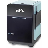
natural_image
Exterior view of a laboratory instrument labeled 'Weller' with digital display and control buttons (no readable text beyond branding)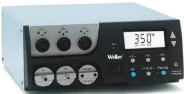
EN Translation of the original instructions
natural_image
Circular icon with a lowercase 'i' in the center, commonly used to denote information (no additional text or symbols)
www.weller-tools.com
MANUAL

VIDEO

FAQ
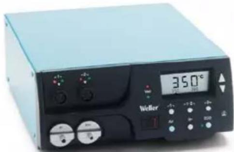
WR2


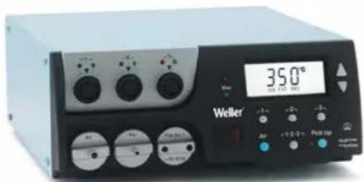
WR3M
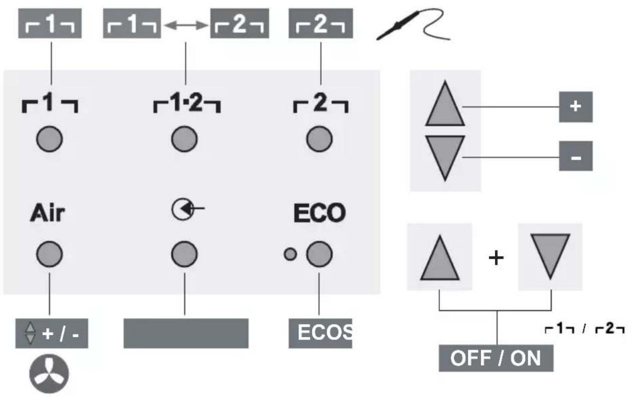
Quick Reference WR 2
flowchart
graph TD
    A["1"] --> B["1"]
    C["1"] <--> D["2"]
    E["2"] --> F["2"]
    G["Air"] --> H["+/-"]
    I["ECO"] --> J["ECOS"]
    K["OFF/ON"] --> L["+"]
    M["△ + ▽"] --> N["1/2"]
    style A fill:#ccc,stroke:#333
    style C fill:#ccc,stroke:#333
    style E fill:#ccc,stroke:#333
    style G fill:#ccc,stroke:#333
    style I fill:#ccc,stroke:#333
    style K fill:#ccc,stroke:#333
    style M fill:#ccc,stroke:#333
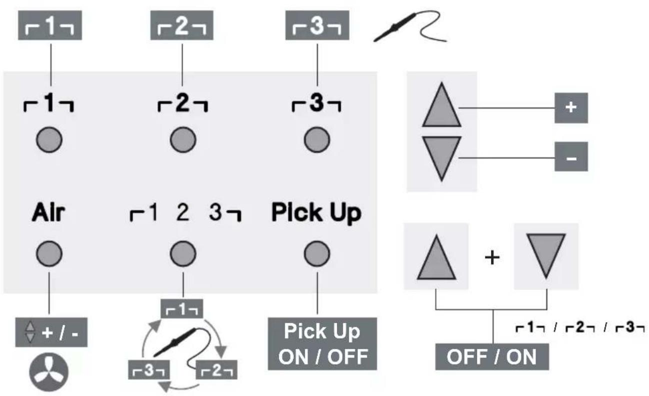
Quick Reference WR 3M
flowchart
graph TD
    A["1"] --> B["1"]
    C["2"] --> D["2"]
    E["3"] --> F["3"]
    G["Air"] --> H["+/-"]
    I["Pick Up"] --> J["1 2 3"]
    K["Pick Up ON/OFF"] --> L["1/2/3"]
    M["Off/ON"] --> N["1/2/3"]
    O["+"] --> P["+"]
    Q["-"] --> R["−"]
DE Menüaufruf
GB Open Menu
ES Acceso al Menú
FR Appel du menu
IT Richiama il menu
natural_image
Simple line drawing of an open box with a dotted arrow pointing upward (no text or symbols)
WR 2 WR 3M
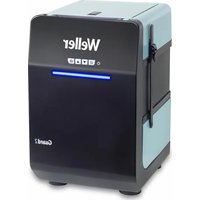
natural_image
Exterior view of a laboratory instrument with digital display and control buttons (no readable text or symbols)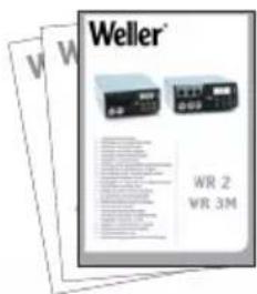

natural_image
Close-up of a WHP 80 WSB 1 microcontroller with visible internal components and wiring (no text or symbols on the device itself)
natural_image
Exterior view of a white electronic device with ventilation slots and a central screen (no visible text or symbols)
natural_image
Close-up of a mechanical component with a central cylindrical shaft and threaded base (no visible text or symbols)
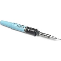
natural_image
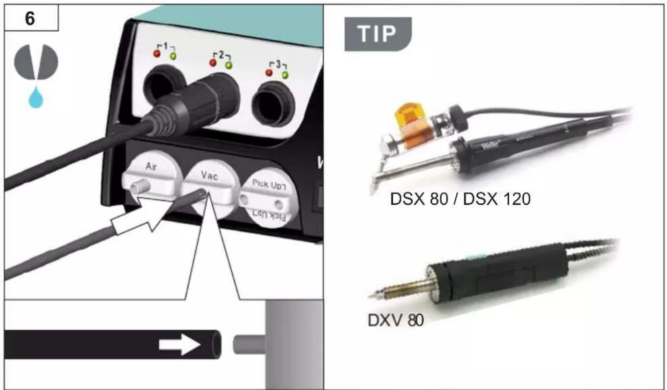
Blue soldering iron with metal terminals and probe tip (no visible text or symbols)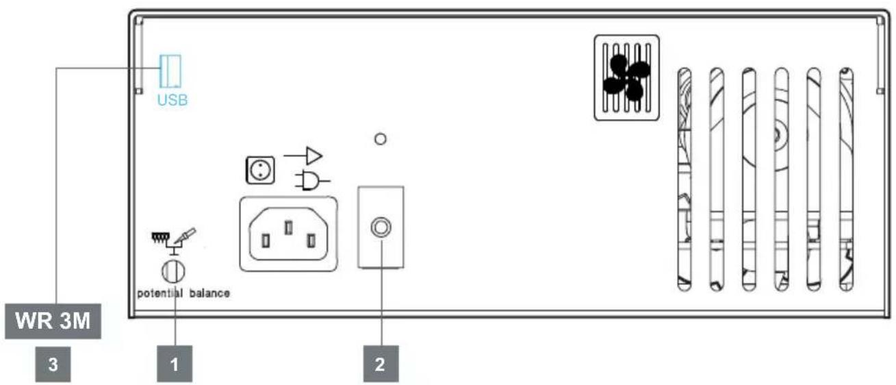
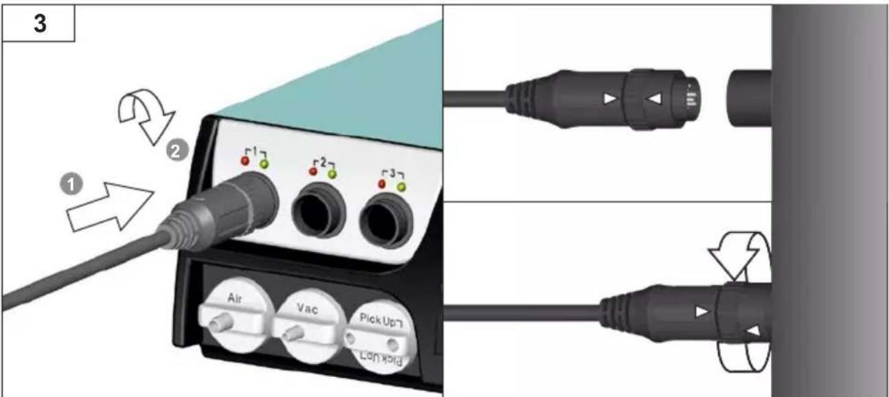
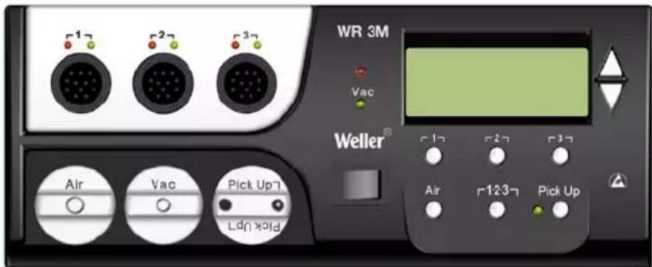
GB Active channel / Visual control check
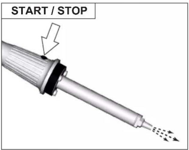
GB Starting up the device
natural_image
Illustration of a scientific instrument labeled 'Weller' with control knobs and display (no readable text beyond labels)WR 3M max. 3 ×
DE Filterwechsel
GB Filter change
ES Cambio de filtro
natural_image
Close-up of a black electronic device with three ports and a small metallic connector (no visible text or symbols)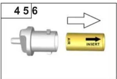
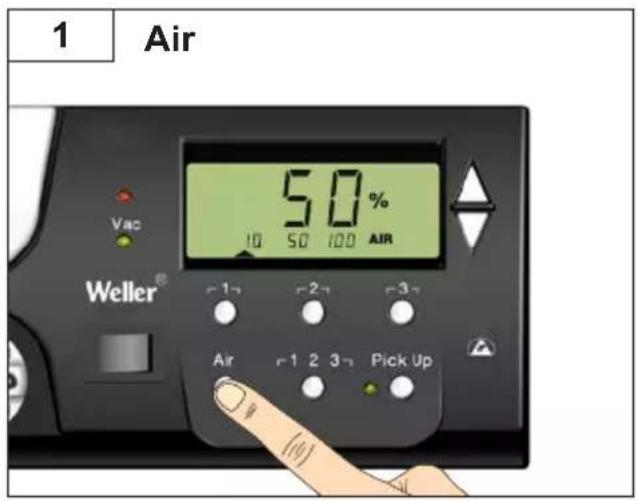
DE Heißluft
GB Hot air
ES Aire caliente
FR Air chaud
IT Aria calda
PT Ar quente
NL Hete lucht
sv Hetluft
DK Varmluft
FI Kuumailma
GR Καυτός αέρας
TR Sicak hava
CZ Horký vzduch
PL Gorące powietrze
HU Forrólevegő
SK Horúci vzduch
SL Vroč zrak
EE kuum öhk
LV Karsts gaiss
LT Karštas oras
BG Горещ въздух
RO Aer cald
HR Vrući zrak
RU Нагретый воздух
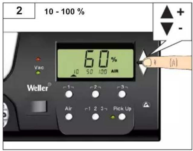
DE Bedienprinzip
GB Operating principle
ES Manejo
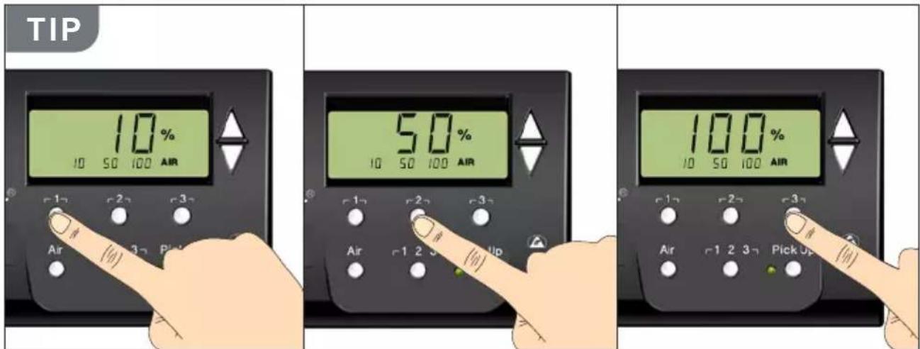
DE Kanal auswählen
GB Select channel
ES Selecionar canal
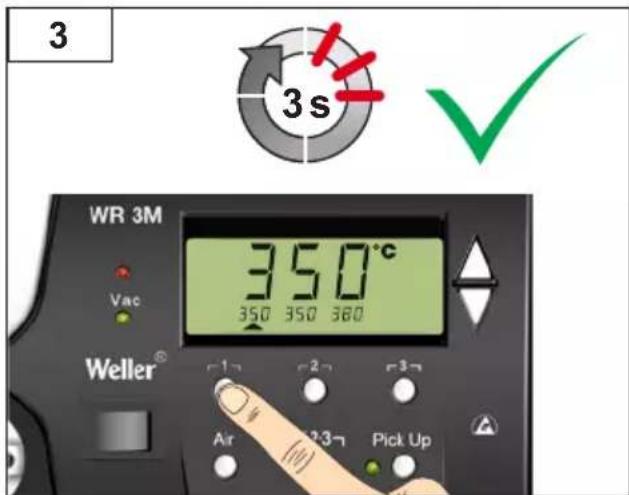
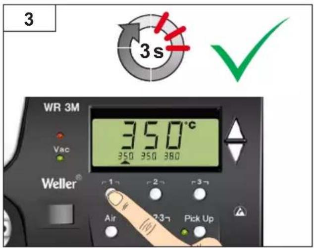
GB Select fixed temperature
GB Set and save fixed temperature
DE Kanal auswählen
GB Select channel
ES Selecionar canal
GB Select fixed temperature
| DE Deutsch | Sicherheitshinweise | Bestimmungsgemäße Verwendung | Benutzergruppen | Pfl ege und Wartung | Garantie | Technische Daten | Symbole | 31 |
| EN English | Safety information | Specifi ed Conditions Of Use | User groups | Care and maintenance | Warranty | Technical Data | Symbols | 43 |
| ES Español | Advertencias de seguridad | Aplicación De Acuerdo A La Finalidad | Grupo de usuarios | Cuidado y mantenimiento | Garantía | Datos Técnicos | Símbolos | 55 |
| FR Français | Consignes de sécurité | Utilisation Conforme Aux Prescriptions | Groupes d'utilisateurs | Entretien et maintenance | Garantie | Caractéristiques Techniques | Symboles | 67 |
| IT Italiano | Avvertenze per la sicurezza | Utilizzo Conforme | Gruppi utenti | Cura e manutenzione | Garanzia | Dati Tecnici | Simboli | 79 |
| PT Portugues | Indicações de segurança | Utilização Autorizada | Grupos de utilizadores | Conservação e manutenção | Garantia | Características Técnicas | Símbolos | 91 |
| NL Nederlands | Veiligheidsinstructies | Voorgeschreven Gebruik Van Het Systeem | Gebruikersgroepen | onderhouden | Garantie | Technische Gegevens | Symbolen | 103 |
| SV Svenska | Säkerhetsanvisningar | Använd Maskinen Enligt Anvisningarna | Användarkategorier | skötsel och underhåll | Garanti | Tekniska Data | Symboler | 115 |
| DK Dansk | Sikkerhedsanvisninger | Tiltænkt Formål | Brugergrupper | Pleje og vedligeholdelse | Garanti | Tekniske Data | Symboler | 127 |
| FI Suomi | Turvallisuusohjeet | Tarkoituksenmukainen Käyttö | Käyttäjäryhmät | aseman hoito ja huolto | Takuu | Tekniset Arvot | Symbolit | 139 |
| GR Ελληνικα | Υποδείξεις ασφαλείας | Хρήση σύμφωνα με το σκοπό προορισμού | Ομάδες χρηστών | Φροντίδα και συντήρηση της συσκευής | Εγγύηση | Τεχνικά στοιχεία | Σύμβολα | 151 |
| TR Türkçe | Güvenlik uyarıları | Kullanim | Kullanıcı grupları | temizliği ve bakımı | Garanti | Teknik Veriler | Semboller | 163 |
| CZ Český | Bezpečnostní pokyny | Použití v souladu s určením | Uživatelské skupiny | Údržba a servisní práce ohledně | Záruka | Technické údaje | Symboly | 175 |
| PL Polski | Bezpieczeństwo | Użytkowanie | Grupy użytkowników | Pielęgnacja i konserwacja urządzenia | Gwarancja | Dane Techniczne | Symbole | 187 |
| HU Magyar | Biztonsági utasítások | Rendeltetésszerű használat | Felhasználói csoportok | Ápolás és karbantar-tás | Garancia | Műszaki Adatok | Szimbólumok | 199 |
| SK Slovensky | Bezpečnostné pokyny | Použivanie v súlade s určeným účelom použitia | Skupiny použivateľov | Ošetrovanie a údržba | Záruka | Technické údaje | Symboly | 211 |
| SL Slovenščina | Varnostna navodila | Uporaba v skladu s predpisi | Skupine uporabnikov | Nega in vzdrževanje | Garancija | Tehniční Podatki | Simboli | 223 |
| EE Eesti | Ohutusjuhised | Kasutusotstarbele vastav käitamine | Kasutajarühmad | Hooldamine ja teenindami-ne | Garantii | Tehnilised Andmed | Sümbol | 235 |
| LV Latviski | Drošības norādes | Atbilstoša lietošana | Lietotāju grupas | Apkope un kopšana | Garantija | Tehniskie dati | Simboli | 247 |
| LT Lietuviškai | Saugos taisyklės | Naudojimas pagal paskirtį | Naudotojų grupės | Įprastinė ir techninė priežiūra | Garantija | Techniniai duomenys | Simboliai | 259 |
| BG Български | Инструкции за безопасна работа | Използване по предназначение | Потребителски групи | Обслужване и поддържане | Гаранция | Технически данни | Символи | 271 |
| RO Român | Indicatii de securitate | Utilizarea conformă cu destinația | Grupe de utilizatori | ďngrijirea și întreținerea curentă | Garanția pentru produs | Date tehnice | Simbolur | 283 |
| HR Hrvatski | Sigurnosna upozorenja | Namjenska uporaba | Skupine korisnika | Njega i servisiranje | Jamstvo | Tehnički podaci | Simboli | 295 |
| RU Русский | Указания по технике безопасности | Использование по назначению | Группы пользователей | Уход и техническое обслуживание | Гарантия | Технические характеристики | Символы | 307 |
Thank you for the confidence you have shown in buying this device.
The device has been manufactured in accordance with the most rigorous quality standards which ensure that it operates perfectly.

Read these instructions and the accompanying safety information carefully before starting up the device starting work with the device.
Keep these instructions in a place that is accessible to all users.
These instructions contain important information which will help you to start up, operate and service the device safely and correctly as well as to eliminate simple faults and malfunctions yourselves.
The device has been manufactured in accordance with state-of-the-art technology and acknowledged regulations concerning safety.
There is nevertheless the risk of personal injury and damage to property if you fail to observe the safety information set out in the accompanying booklet and the warnings given in these instructions.
Safety information
For safety reasons, children and youths under the age of 16, as well as persons who are not familiar with these operating instructions, may not use the device. Children should be supervised in order to ensure that they do not play with the tool. This device is not intended for use by persons (including children) with limited physical, sensory or mental aptitude, or by persons who lack knowledge or experience in handling the device.

Warning! Electrical shock
Connecting the control unit incorrectly poses a risk of injury due to electric shock and can damage the device.
Carefully read the attached safety information, the safety information accompanying these operating instructions as well as the operating instructions for your control unit before putting the control unit into operation and observe the safety precautions specified therein.
Only connect WELLER tools.
If the device is faulty, active electrical conductors may be bare or the PE conductor may not be functional.
Repairs must always be referred to a Weller-trained specialist.
If the electrical tool's power supply cord is damaged, it must be replaced with a specially prefabricated power supply cord available through the customer service organization.

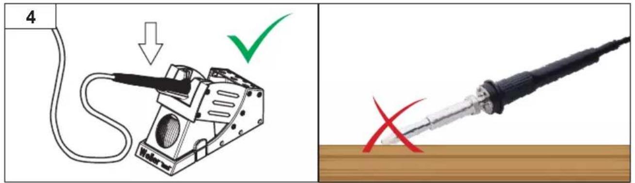
Warning! Risk of burns
Risk of burns from the soldering tool while the control unit is operating. Tools may still be hot long after they have been switched off.
□ Always place the soldering tool in the safety rest while not in use.
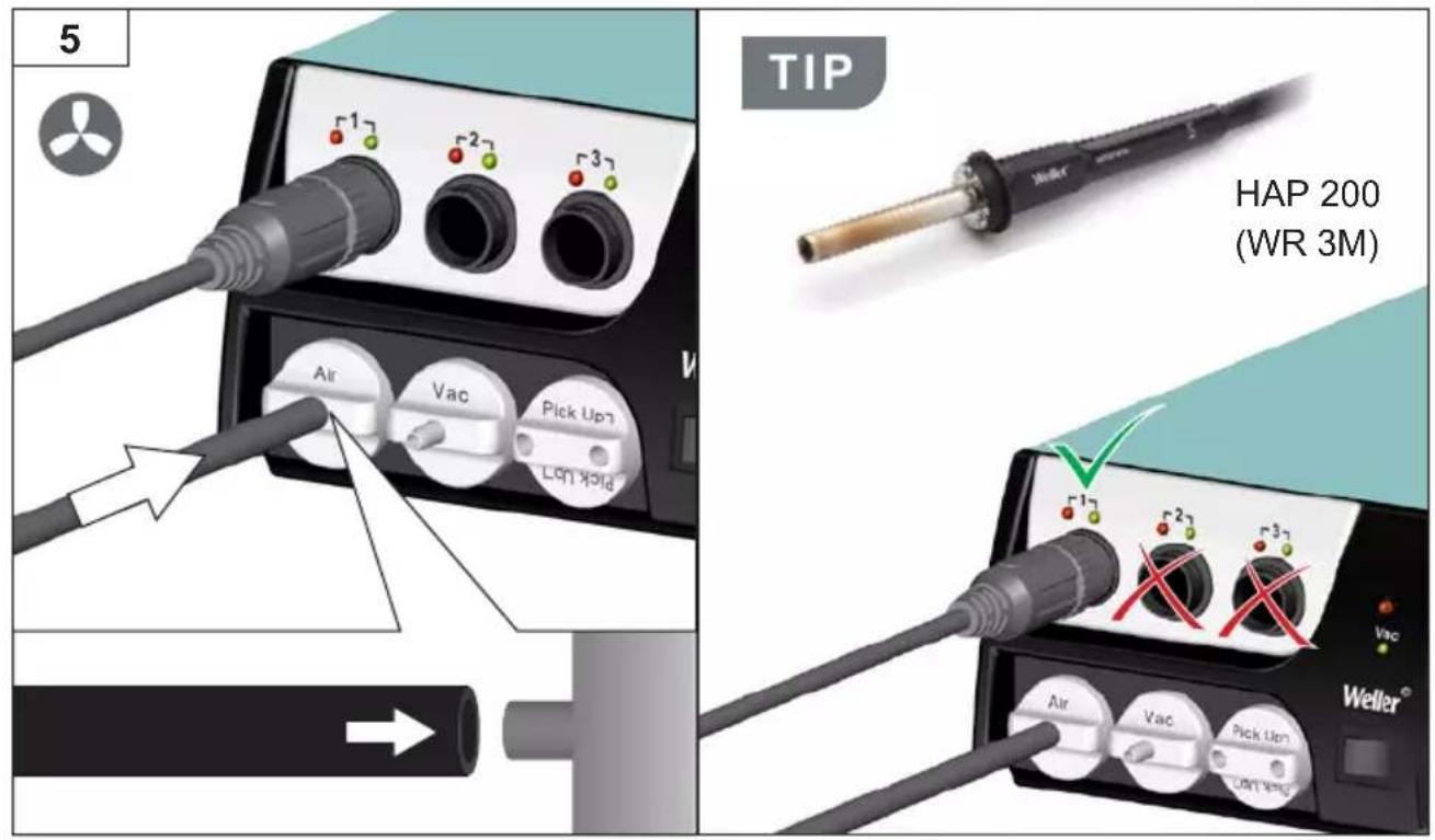
Only connect the vacuum and hot air at the designated points.
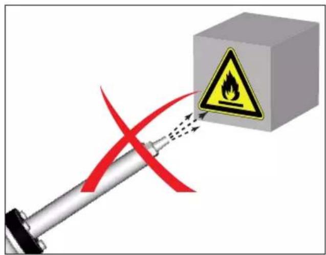
☐ Do not direct hot air soldering tools at people or inflammable objects.

Warning! Fire and explosion hazard! Hot tools represent a fire hazard
Always place the soldering tool in the safety rest while not in use.
Do not direct hot air soldering tools at people or inflammable objects.
Keep explosive and flammable objects well away from the device.
Do not cover the device.

Warning! Danger of injury
The device or parts of the device may fall off during transportation.
Specified Conditions Of Use
Supply unit for WELLER soldering tools. Use the repair station only for the purpose indicated in the operating instructions of soldering and desoldering under the conditions specified herein.

Flammable gases and liquids may not be extracted.
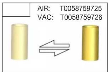
The device may only be used with correctly fitted and suitable filter cartridges.
Replace filter cartridges when full.
Only use the device indoors. Protect against moisture and direct sunlight.
Intended use of the soldering station/ desoldering station also includes the requirement that you
adhere to these instructions,
observe all other accompanying documents,
☐ comply with national accident prevention guidelines applicable at the place of use.
The manufacturer will not be liable for unauthorized modifications to the device.
User groups
Due to differing degrees of risk and potential hazards, several work steps may only be performed by trained experts.
| Work step User groups | |
| Default soldering parameters Specialist personnel with technical training | |
| Replacing electrical replacement parts Electricians | |
| Default maintenance intervals Safety expert | |
| OperationFilter change | Non-specialists |
| OperationFilter changeReplacing electrical replacement parts | Technical trainees under the guidance and supervision of a trained expert |
Starting up the device
Caution!
Please adhere to the operating instructions of the connected devices.
Put the tool into operation as described in the chapter „Placing into operation“.

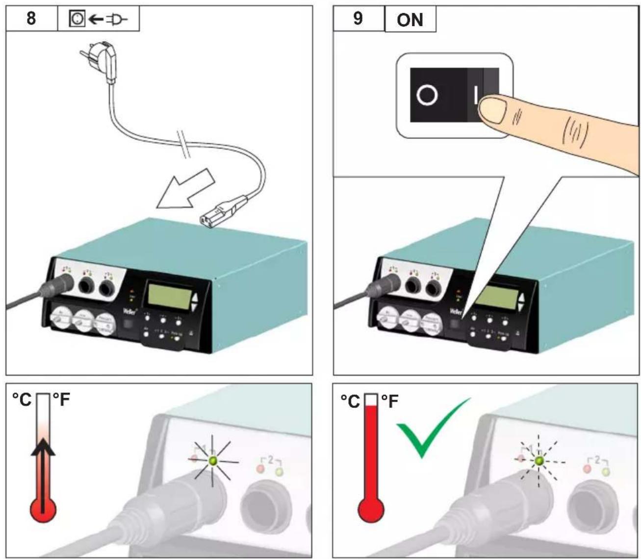
Check to see if the mains voltage matches the ratings on the nameplate.
Make sure the machine is switched off before plugging in.
After the device has been switched on, the microprocessor carries out a self-test in which all the segments are briefly in operation.
Soldering and desoldering
Carry out soldering work as directed in the operating instructions of your connected soldering tool.
Handling the soldering tips
☐ Coat the selective and tinnable soldering tip with solder when heating it up for the first time. This removes oxide coatings which have formed during storage and impurities from the soldering tip.
☐ Make sure that the soldering tip is well coated with solder during breaks between soldering work and prior to storage of the device.
Do not use aggressive fluxing agents.
☐ Always make sure that the soldering tips are fitted properly.
Select as low a working temperature as possible.
☐ Select the largest possible soldering tip shape for the application.
Rule of thumb: the soldering tip should be roughly as large as the soldering pad.
Coat the soldering tip well with solder to ensure
that there is efficient heat transfer between the soldering tip and the soldering area.
☐ Prior to extended breaks between soldering work, switch off the soldering system or use the Weller function to reduce the temperature when the soldering equipment is not in use.
☐ Coat the tip with solder prior to storage if you do not intend to use the soldering iron for an extended period of time.
☐ Apply solder directly to the soldering area, not to the soldering tip.
Change the soldering tips using the designated tool.
Do not apply mechanical force to the soldering tip.
Notice
The control units have been adapted to hold a medium-sized soldering tip. Discrepancies may occur if the tip is changed or a different shaped tip is used.
Overload cut-out
To avoid overloading the station, power output is automatically reduced in the event of an overload.
Equipotential bonding
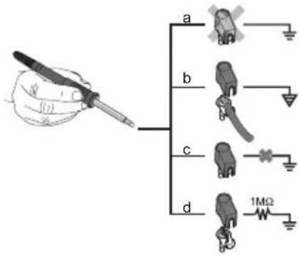
Four variants are possible by connecting the 3.5 mm jack socket differently:
| a Hard-grounded supplied | without plug. |
| b Equipotential bonding | with plug, equaliser at centre contact. |
| c Floating with plug | |
| d Soft-grounded with plug | and soldered resistor. Ground-ed through selected resistor. |
Carrying out a firmware update (WR 3M)
Notice
The control unit is equipped with a Mini USB port. To use the USB port, Weller provides software on so you can carry out a software update ("Firmware Updater") on your control unit.
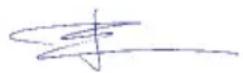
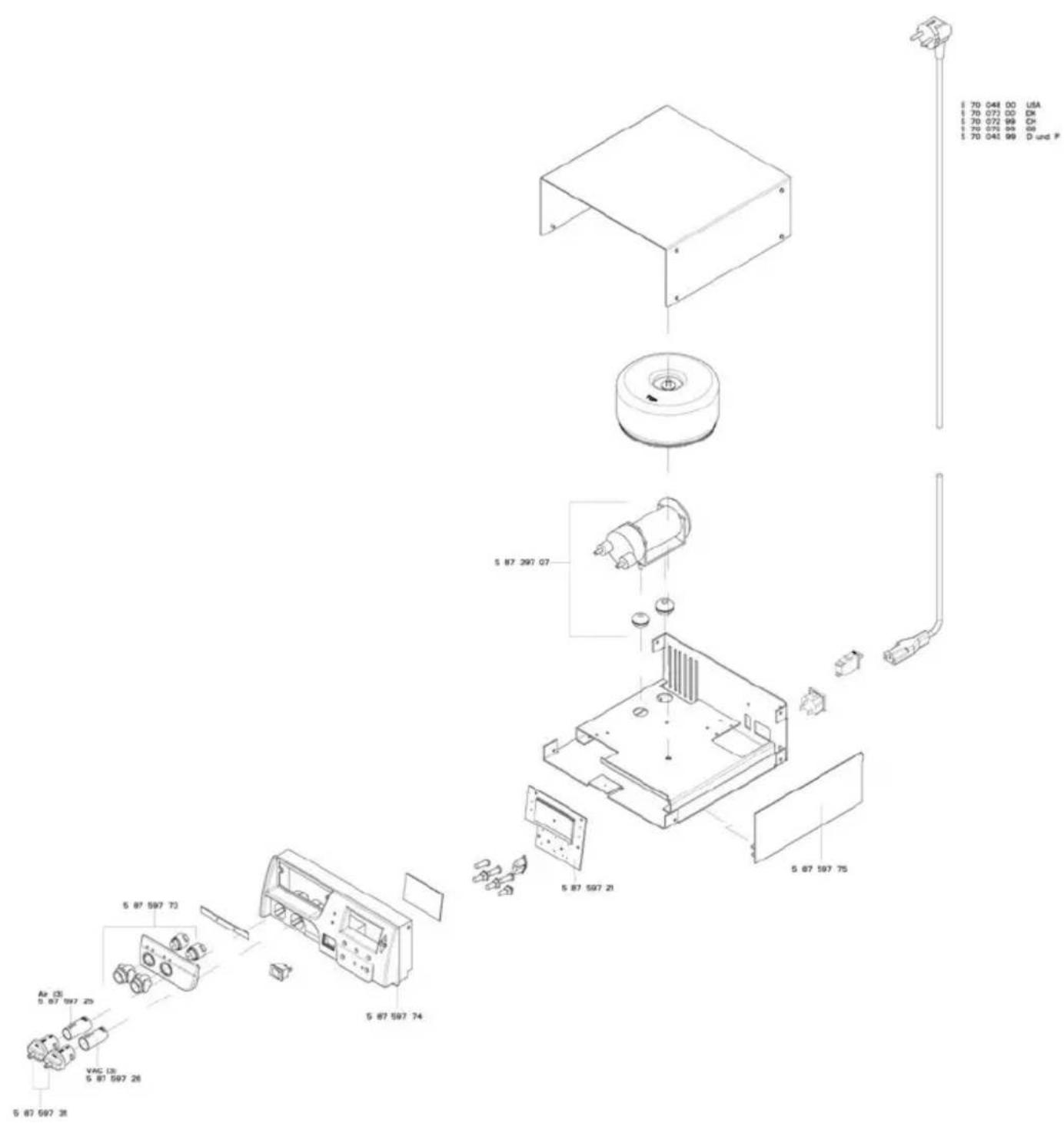
Care and maintenance

Warning!
<Before doing any work on the machine, pull the plug out of the socket.

Warning!
Use original replacement parts only.

Warning! Risk of burns
Only replace solder tips when cold
Replace and clean suction nozzles only when hot and using the suitable tool
Only replace hot air nozzles using the suitable tool
☐ Only clean or replace solder collection tubes when cold
Clean the operator panel, if dirty, using a suitable cleaning cloth.
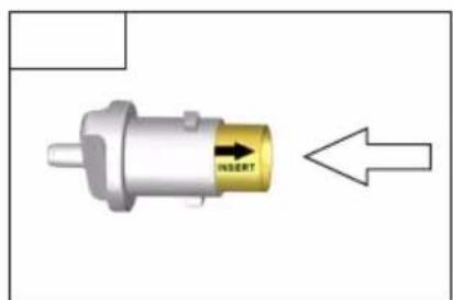
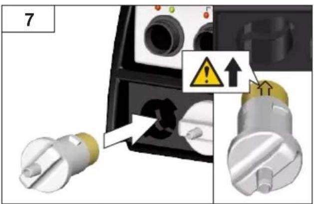
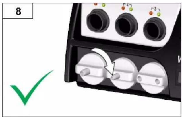
Filter change
Check the filter regularly for contamination, and replace it if necessary.
Warning!
Failure to use a filter will cause irreparable damage to the vacuum pump.
☐ Check before starting soldering whether a main filter is inserted.
Contaminated filters must be treated as special waste.
Dispose of replaced equipment parts, filters or old devices in accordance with the rules and regulations applicable in your country.
Wear suitable protective gear.
Standby Temp. (STANDBY)

Menu access

After activating the Setback function or after pushing the ECO button (WR 2), the temperature is automatically reduced to Standby temperature. The display flashes the actual temperature. <STANDBY appears on the display.
Setback time (SETBACK)

Menu access

If the soldering tool is not in use, the temperature is reduced to Standby temperature on expiration of the preset Setback time.
SETBACK appears on the display.
To exit Standby mode, push the „UP / DOWN“ buttons or ECO (WR 2).
Depending on the tool in use, the finger switch or the safety rest deactivates Standby mode.
| Option Description | |
| 0 min Deactivated (Default setting) | |
| ON After placing the soldering iron into the safety rest, the temperature is immediately reduced to standby level. | |
| 1-999 min | Setback time Individually adjustable |
AUTO OFF time (automatic switch-off time)

Menu access

If the soldering tool is not in use, the soldering tool is switched off on expiration of the AUTO-OFF time.
The actual temperature flashes on the display and serves as residual-heat indicator. „OFF“ appears on the display. A flashing dash appears on the display below 50 °C (122 °F).
| Option Description | |
| 0 min Deactivated (Default setting) | |
| 1-999 min | AUTO-OFF time, can be set individually. |
Temperature-Offset (Offset)

Menu access

The actual soldering-tip temperature can be adapted by entering a temperature offset around ±40 ^ ( ±72 ^ ).
Temperature window (WINDOW)

Menu access

Starting from a set, locked temperature, it is possible to set a temperature window of ± 1 - 99^ ( ± 1 - 180^ ) using the WINDOW function. To use the WINDOW function, the repair station must be interlocked.
Temperature units (°C/°F)

Menu access

Option Description
| °C Celsius | |
| °F Fahrenheit |
Max. hot air duration (HAP On)

Menu access

The on-time of the hot air flow of the HAP 200 can be limited in increments of 1 to between 0 and 60 sec. The set time is then identical for all 3 channels.
The factory default is s („OFF“), i.e. air flows only as long as the button on the hot air tool or the optional footswitch is pressed.
Option Description
| OFF No duration defined(Default setting) |
| 1-60 s Individually adjustable |
Vacuum pre-feed (VAC On)

Menu access

In order to prevent the pump from starting prematurely or to ensure a defined soldering-joint preheating time, it is possible to set an ON delay.
Option Description
| 0 sec OFF: vacuum pre-feed function is OFF (Default setting) |
| 1-9 sec ON: vacuum pre-feed time, individually |
Vacuum run-on (VAC Off)

Menu access

To prevent the desoldering iron from becoming clogged, it is possible to set a vacuum run-on time. (factory setting 2 s)
Option Description
| 0 sec OFF: vacuum run-on function is OFF(Default setting) |
| 1-5 sec ON: vacuum run-on time, individuallyadjustable |
lock function

Menu access

After the lock has been activated, only the following buttons on the soldering station are enabled:
WR 2: ^1,^1·2,^2,ECO,AIR
WR 3M: ^1,^2,^3^1·2·3 , Pick Up, AIR
All other settings are disabled until the repair station is unlocked again.
Notice
If you want only one temperature value to be selectable, the control keys fixed temperature keys) must be set to the same temperature value.
Locking the soldering station
Select menu option. „OFF“ appears on the display. The key symbol is flashing.
Set the desired three-digit locking code (between 001 and 999) using the UP / DOWN buttons.
WR 2: Press button 2 for 5 seconds.
WR 3M: Press button 3 for 5 seconds.
The code is stored.
The key symbol is displayed.
Unlocking the soldering station
- Select menu option. „ON“ appears on the display.
- Set the three-digit locking code using the UP / DOWN buttons.
- WR 2: Press button 2 . WR 3M: Press button 3 .
- The station is now unlocked. The display switches to the main menu.
Forgotten code?
Please contact our Customer Service: technical-service@weller-tools.com
Pressure gauge threshold (LEVEL)

Menu access

This function can be used to define the maintenance interval of the desoldering tool. This is done by setting the value in mbar at which the electric pressure gauge issues a warning signal when the intake system is contaminated (LED of the vacuum pump switches from green to red). The set value is dependent on the suction nozzles used.
Adjustable -400 mbar to -800 mbar
factory setting -600 mbar
- The system (tips and filter) must be free.
- Select the menu item „Pressure gauge threshold“ in the menu.
- Set the „Pressure gauge threshold“ pressure value with the UP or DOWN button. The status LED switches back and forth between red and green. Use the UP button to increase vacuum by 50 to 80 mbar, then pinch the vacuum tube and check whether the LED switches from green to red.
Station code (Remote ID)

Menu access

WR 3M
A station code (Remote ID) can be assigned to each station, allowing the station to be clearly identified via the USB port.
Option Description
0-999 Individually adjustable
Calibration (Factory Calibration Check FCC)

Menu access

You can use the FCC function to check the temperature precision of the repair station and even out possible deviations. For this purpose, the soldering-tip temperature must be measured with an external temperature meter and a temperature measuring tip assigned to the soldering tool. The corresponding channel must be selected prior to calibration.
-
Insert the temperature sensor (0.5 mm) of the external temperature meter into the temperature measuring tip.
-
Select the menu item FCC in Menu 2.
-
a) Press the DOWN button. -> Calibration point 100 °C / 210 °F is selected. b) Press the UP button. -> Calibration point 450 °C / 840 °F is selected.
The soldering tip is now heated up. The control indicator flashes as soon as the temperature is constant.
-
Compare the temperatures indicated by the meter with the readings on the display.
-
WR 2: Push the 1 · 2 (Set) button to confirm the adjusted value.
WR 3M: Push the 1· 23 (Set) button to confirm the adjusted value.
The temperature deviation is now reset to 0. Calibration at 100 °C / 210 °F / 450 °C / 840 °F is now complete.
- Use the UP or DOWN button to set the difference between the value indicated on the external meter and the value indicated on the repair station. Maximum possible temperature adjustment ± 40 ^ C ( ± 70 ^ F).
WR 2: Push button 2 to exit the menu option (EXIT).
WR 3M: Push button 3 to exit the menu option (EXIT).
- WR 2: Exit Menu 2 with button 2 .
WR 3M: Exit Menu 3 with button 27.
Resetting calibration to factory settings
-
Select the menu item FCC in Menu 2.
-
WR 2: Press and hold down button 2 .
WR 3M: Press and hold down button 3 .
- Then press the UP and DOWN buttons simultaneously. „FSE“ (Factory Setting Enabled) appears on the display.
The repair station is now reset to the factory calibration.
Activation / Deactivating the special button (SP Button)

Menu access

-2-
WR 2
After activating the special button, it can be used as a shortcut back to Menu 1. The function previously selected is saved when the menu is exited with the special button.
Option Description
OFF Deactivated (Default setting)
ON Special button activated
Activation / Deactivating the ECO button (ECO)

Menu access

-2-
WR 2
After activating the ECO button, it can be used to set all channels to Standby mode. The green LED lights up and the channels are set to the set standby temperature. If a safety rest is in use, the function is reset when the tool is removed from the holder.
Option Description
OFF Deactivated (Default setting)
ON ECO button activated
Button lock HAP 200 (HAP LOC)

Menu access

-2-
WR 3M
This function can be used to adjust the factory button presets of the WXAHP tool.
The HAP 200 is switched on the first time the button is pressed and switched off the next time the button is pressed.
Option Description
OFF Deactivated (Default setting)
ON HAP LOC activated
Perform. Mode Menu access -2-

▶
The function determines the heating characteristics of the soldering tool to achieve the set tool temperature.
Option Description
LO Slow heating
HI rapid heating
Resetting to factory settings (FSE)
Select the menu option FSE in menu 1.
WR 2:Press and hold down button 2 .
1Open special functions menu „1“ (push UP & DOWN buttons simultaneously for 2sec.)
-
Press and hold down button 2 .
-
Then press the UP and DOWN buttons simultaneously. FSE appears on the display. (Factory Setting Enabled).
The repair station is now reset to the factory settings.
Reset the calibration values to the factory settings
-
Open special functions menu „2“ (push UP & DOWN buttons simultaneously for 4sec.)
-
Select menu option „FCC“.
-
Press and hold down button 2 .
-
Then press the UP and DOWN buttons simultaneously. FSE appears on the display. (Factory Setting Enabled).
The repair station is now reset to the factory settings.
WR 3M: Press and hold down button 3 .
-
Open special functions menu „1“ (push UP & DOWN buttons simultaneously for 2sec.)
-
Push button 3 and hold it down.
-
Then press the UP and DOWN buttons simultaneously. FSE appears on the display. (Factory Setting Enabled).
The repair station is now reset to the factory settings.
Reset the calibration values to the factory settings
-
Open special functions menu „2“ (push UP & DOWN buttons simultaneously for 4sec.)
-
Select menu option „FCC“.
-
Push button 3 and hold it down.
-
Then press the UP and DOWN buttons simultaneously. FSE appears on the display. (Factory Setting Enabled).
The repair station is now reset to the factory settings.
| Repair station WR 3M WR 2 | ||
| Dimensions L x W x H (mm) | 273 x 235 x 102 | |
| Dimensions L x W x H (Inch) | 10.75 x 9.25 x 4.02 | |
| Mains supply voltage 230 V ~ 50/60 | Hz | 240/120 V ~ 50/60 Hz | |
| 120 V ~ 60 Hz | 100V ~ 50/60 Hz | ||
| Power consumption 400 W 300 W | ||
| Safety class I, antistatic housing | III, Soldering tool | |
| Fuse Overcurrent release 230 V; 2,0 A | 120 V; 4,0 A | 1,6 A |
| Temperature (Tool dependent) °C | 50 - 450 (550) | |
| Temperature (Tool dependent) °F | 150 - 850 (999) | |
| Temperature accuracy °C | ± 9 | |
| Temperature accuracy °F | ± 17 | |
| Temperature accuracy Hot air °C ± 30 | ||
| Temperature accuracy Hot air °F ± 54 | ||
| Temperature stability °C | ± 2 | |
| Temperature stability °F | ± 4 | |
| Equipotential bonding Via 3.5 mm pawl socket on back of unit(delivery form: hard grounded without jack plug) | ||
| Display LCD | ||
| USB port The control unit comes with a front-side USBport for installing firmware updates, configurationand monitoring. | - | |
| Pump (Intermittent mode (30/30) s) Max. vacuum 0,7 barMaximum quantity supplied 18 l/minMax. hot air 15 l/min | ||
| Additional vacuum pump Max. vacuum 0,5 barMaximum quantity supplied 1,7 l/min | - | |
Error messages and error clearance
| Message/symptom Possible cause | Use Remedial measures | |
| Display: „--- | Tool has not been detectedTool defective | Check connection of tool to deviceCheck connected tool |
| No display function (display OFF) | No mains supply voltage | Turn on mains power switchCheck mains supply voltageCheck device fuse |
| No vacuum at desoldering tool | Vakuum nicht angeschlossenDesoldering nozzle cloggedPump faulty | Connect vacuum hose to vacuum connectionService desoldering nozzle using cleaning tool |
| Insufficient vacuum at desoldering tool | Filter cartridge on desoldering tool fullMain filter full | Change filter cartridge on desoldering tool fullChange the main filter element on the soldering station |
| Hot air tool has no air | Air hose not connectedMain filter full | Connect or check air hoseChange the main filter element on the soldering station |
Symbols

Caution!

Read the operating instructions!
Before performing work of any kind on the unit, always disconnect the power plug from the socket.

ESD-compatible design and ESD-compatible workstation
Equipotential bonding

CE mark of conformity

British Conformity Mark

Fuse

Safety transformer

Soldering
Desoldering

Hot air
Disposal
Waste light sources have to be removed from equipment. Check with your local authority or retailer for recycling advice and collection point. According to local regulations retailers may have an obligation to take back waste electrical and electronic equipment free of charge. Your contribution to re-use and recycling of waste electrical and electronic equipment helps to reduce the demand of raw materials. Waste electrical and electronic equipment contain valuable, recyclable materials, which can adversely impact the environment and the human health, if not disposed of in an environmentally compatible manner. Delete personal data from waste equipment, if any.
Contaminated filters must be treated as special waste. Dispose of replaced equipment parts, filters or old devices in accordance with the rules and regulations applicable in your country.
Warranty
Claims by the buyer for physical defects are time-barred after a period of one year from delivery to the buyer. This does not apply to claims by the buyer for indemnification in accordance with §§ 478, 479 BGB (German Federal Law Gazette).
We shall only be liable for claims arising from a warranty furnished by us if the quality or durability warranty has been furnished by use in writing and using the term „Warranty“.
The warranty shall be void if damage is due to improper use and if the device has been tampered with by unauthorized persons.
Subject to technical alterations and amendments.
For more information please visit www.weller-tools.com.
Coupure de surcharge
Calibrage (Factory Calibration Check FCC)
Appel du menu ▶ - 2 -
Calibrazione (Factory Calibration Check FCC)
Calibragem (Factory Calibration Check FCC)
Stationsidentificatie (Remote ID)

Menu-oproep

-2-
WR 3M
Stationsidentitet (Remote ID)

Menyanrop

WR 3M
Kalibrasyon (Factory Calibration Check FCC)

Menü arama
▶ - 2 -
Calibrare (Factory Calibration Check FCC)
EN EC declaration of conformity
We hereby declare that the products described herein comply with the following guidelines:
Authorised to compile technical documentation.
Autoriza la recopilación de la documentación técnica. autorise à réunir les documentations techniques.
UK declaration of conformity
We hereby declare that the products described herein comply with the following guidelines:
2008 No.1597, SI 2012 No.3032, SI 2016 No.1091
Besigheim, 2023-08-25
Philippe Buidin
Managing director
Authorised to compile technical documentation.
Apex tool Group (UK Operations) Limited
Piccadilly, Tamworth
Staffordshire B78 2ER
Product Registration
www.weller-tools.com/registration
GERMANY
Weller Tools GmbH
Carl-Benz-Straße 2
74354 Besigheim
Apex Tool Group B. V.
Apex Tool Group UK Ltd
Registered in England,
Company Number 14127816
Registered Office:
C/O TMF Group 13th Floor,
One Angel Court, London,
EC2R 7HJ, United Kingdom
USA
Apex Tool Group, LLC.
Weller Professional Tools Division
1000 Lufkin Road
Apex, NC 27539
+866-498-0484