P5616OT - Thermostat Emos - Free user manual and instructions
Find the device manual for free P5616OT Emos in PDF.

| Product type | Wireless programmable thermostat |
| Brand | Emos |
| Model | P5616OT |
| Category | Thermostat |
| Control unit dimensions | 126 × 84 × 26 mm |
| Switching unit dimensions | 86 × 86 × 36 mm |
| Control unit weight | 180 g |
| Switching unit weight | 146 g |
| Control unit power supply | 2 alkaline AA 1.5 V batteries (LR6) |
| Clock backup power supply | 1 CR2032 3 V battery |
| Switching unit power supply | 230 V AC |
| Temperature measurement range | 0°C to 40°C (resolution 0.1°C, accuracy ±1°C at 20°C) |
| Temperature setting range | 5°C to 35°C (step 0.5°C) |
| Adjustable hysteresis | 0.2°C to 2.0°C (step 0.1°C) |
| Maximum switching load | 230 V AC, 10 A resistive, 4 A inductive |
| Radio frequency | 868 MHz, max power 25 mW e.r.p. |
| Radio range | Up to 80 m in open air |
| Programs | 6 default programs (day/weekend), customizable |
| Operating modes | Auto, Manual, Frost protection, Holiday, Temporary |
| Special functions | Program copy, Button lock, Calibration, Heat/cool mode, OpenTherm |
| Installation | Wall-mounted, requires cutting power supply |
| Included accessories | 2 screws, 2 wall plugs |
| Maintenance | Soft slightly damp cloth, avoid solvents and immersion |
| Safety | Repair by qualified professional only |
Frequently Asked Questions - P5616OT Emos
User questions about P5616OT Emos
0 question about this device. Answer the ones you know or ask your own.
Ask a new question about this device
Download the instructions for your Thermostat in PDF format for free! Find your manual P5616OT - Emos and take your electronic device back in hand. On this page are published all the documents necessary for the use of your device. P5616OT by Emos.
USER MANUAL P5616OT Emos
2
3
natural_image
Simple line drawing of a rectangular frame with two internal doors, no text or symbols present.1
natural_image
Line drawing of a portable electronic device with a screwdriver inserted, labeled '2' (no text or symbols on the device itself)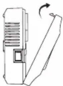
natural_image
Line drawing of a device with a scroll and directional arrow (no text or symbols)3
natural_image
Technical line drawing of an electrical switchgear housing with screwdriver (no text or symbols)4
natural_image
Line drawing of a device with a scroll and directional arrow indicating rotation (no text or symbols)5
4
GB | Wireless Thermostat
The P56160T thermostat is designed for controlling heating and air-conditioning systems.
Important
- Before the first use, make sure to carefully read the operating manual for the thermostat, as well as the manual for the boiler or air-conditioning equipment.
- Turn off power supply before installing the thermostat!
• Installation should be carried out by qualified personnel! - During installation, observe the prescribed standards.
Technical specifications
Switched load: max. 230 V AC; 10 A for resistive load; 4 A for inductive load
Temperature measurement: 0 °C to 40 °C with 0.1 °C resolution accuracy ±1 °C at 20 °C
Temperature setting: 5 °C to 35 °C in 0.5 °C increments
Differential setting: 0.2 °C to 2 °C, in 0.1 °C increments
Power supply:
Control unit with display (transmitter): 2× 1.5 V type AA (LR6) battery
Clock back-up power supply: 1×3 V type CR2032 battery
Switching unit (receiver): 230 V AC
Unit interconnection: via 868 MHz radio signal, 25 mW e.r.p. max.
Transmitter unit range: up to 80 m in an open area
Dimensions and weight:
Control unit: 126 × 84 × 26 mm; 180 g
Switching unit: 86 × 86 × 36 mm; 146 g
Accessories: 2 screws, 2 wall plugs
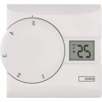
Description of Control Elements (See Fig. 1)
1 - Home (return to home screen)
2 - Next (move to the next option within the current function)
3 - Adjust value setting
4 - Confirm (confirm function selection)
5 - Copy
6 - Holiday mode
7 - Battery compartment
8 - Time and date setting
9 – Select and edit programme (PROG)
10 - Anti-freeze mode (OFF)
11 - Manual mode (MAN)
12 - Automatic mode (AUTO)
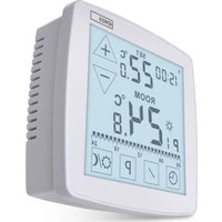
Display Description (See Fig. 2)
13 - Days
14 - Time
15 - Room temperature
16 - Heating
17 - Set temperature
18 – Chosen programme
19 – Holiday mode symbol
20 - Lock display
21 - Temporary mode symbol
22 - Automatic mode (AUTO) symbol
23 - Manual mode (MAN) symbol
24 - Low battery
25 - Cooling
26 - Unit pairing icon
27 - Wireless communication icon
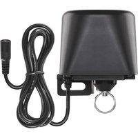
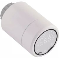
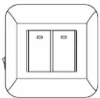
Receiver (Switching Unit) (See Fig. 3)
1 - Main switch (ON/OFF)
position-off position-on
2 - M/A button (red LED)
3 - MANUAL button (green LED)
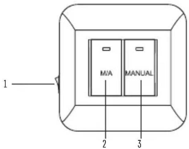
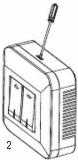
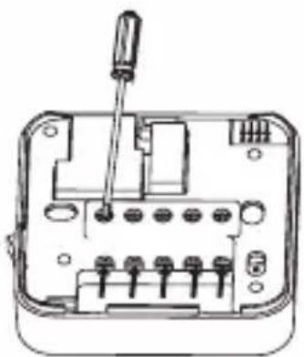
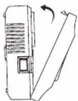
Procedure for Removing the Front of the Switching Unit (See Fig. 4)
2, 3 – use a screwdriver to press down and hold the inner lock, remove the front cover
INSTALLATION
Warning:
Before changing the thermostat, disconnect the heating/air-conditioning system from the main power in your flat. This will prevent potential injury by electric current.
Thermostat Placement
Thermostat location significantly affects its functioning. Choose a room where members of the family spend most of their time, preferably on the inside wall where air circulates freely, with no direct sunlight. Do not place the thermostat in the vicinity of heat sources (such as TV sets, radiators, fridges), or close to a door (due to frequent shocks or vibration). If you do not comply with these recommendations, the thermostat will not control room temperature correctly.
Transmitter Installation
The transmitter can be mounted onto the enclosed stand, or onto a wall.
-
Remove the rear cover.
-
Mark positions for holes.
-
Drill two holes, carefully insert the plastic wall plugs into them and use two screws to fasten the rear thermostat cover.
-
Complete the installation by fitting the switching unit onto the attached rear part of the cover.
Receiver Installation
-
Remove the rear cover.
-
Mark positions for holes onto the wall.
-
Drill two holes, carefully insert the plastic wall plugs into them and use two screws to fasten the rear receiver cover.
-
Connect the wires to the labelled terminals according to the wiring diagram.
-
Complete the installation by fitting the switching unit onto the attached rear part of the cover.
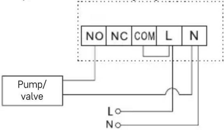
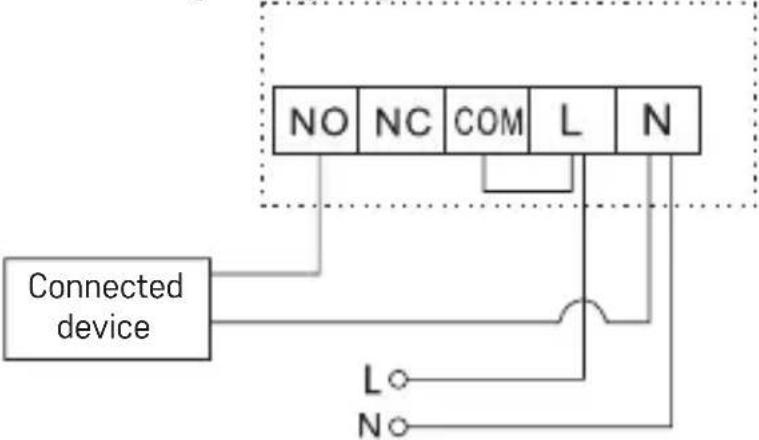
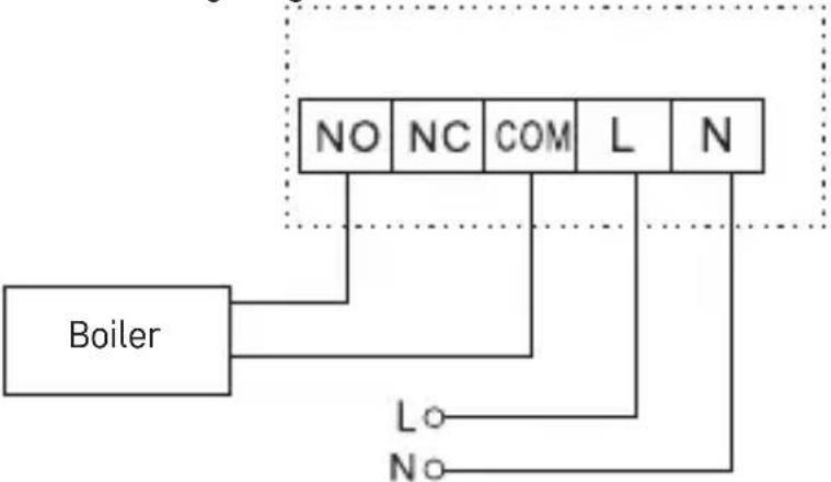
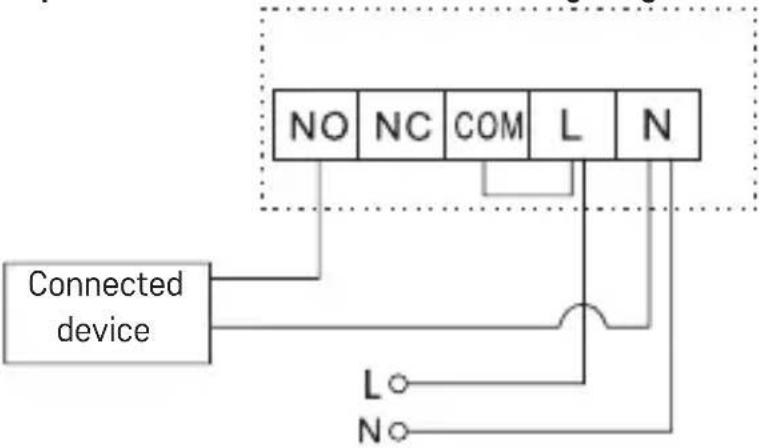
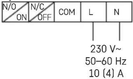
Wiring Diagram
NO normally open contact
NC normally closed contact
COM switch contact
L 230 V AC power connection
N neutral conductor
Pump/Motorised Valve Wiring Diagram
flowchart
graph TD
    A["Pump/ valve"] --> B["NO"]
    A --> C["NC"]
    A --> D["COM"]
    A --> E["L"]
    A --> F["N"]
    B --> G["L"]
    C --> H["O"]
    D --> I["O"]
    E --> J["O"]
    F --> K["O"]
Floor Heating Wiring Diagram
flowchart
graph TD
    A["Connected device"] --> B["NO"]
    A --> C["NC"]
    A --> D["COM"]
    A --> E["L"]
    A --> F["N"]
    B --> G["L"]
    C --> H["N"]
    D --> I["Switch"]
    E --> I
    F --> I
    G --> J["Switch"]
    H --> J
    I --> J
Boiler Wiring Diagram
flowchart
graph TD
    Boiler["Boiler"] --> NO["NO"]
    Boiler --> NC["NC"]
    Boiler --> COM["COM"]
    Boiler --> L["L"]
    Boiler --> N["N"]
    L --> LO["Lo"]
    N --> No["No"]
- The pre-installed wire coupler will not be connected.
Expansion Valve/Electric Drive Wiring Diagram
flowchart
graph TD
    A["Connected device"] --> B["NO"]
    A --> C["NC"]
    A --> D["COM"]
    A --> E["L"]
    A --> F["N"]
    B --> G["L"]
    C --> H["N"]
    D --> I["L"]
    E --> J["N"]
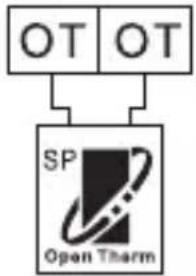
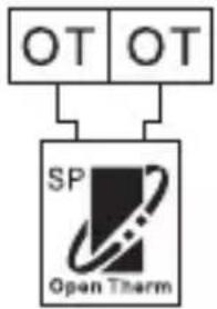
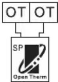
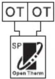
OpenTherm connection

flowchart
graph TD
    A["OT"] --> C["SP Open Therm"]
OT OpenTherm connection
OT OpenTherm connection
Putting the Device into Operation
Remove front cover of the transmitter and insert 2× 1.5 V AA alkaline batteries.
Do not use 1.2 V rechargeable batteries.
Insertion of batteries starts the thermostat and activates the display.
If the thermostat is not working properly, please check the polarity of the batteries, and their state of charge.
If the heating/air-conditioning system is not used for an extended period of time, it is recommended to turn the switching unit off (move the main switch to the position).
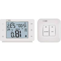
Unit Pairing
-
Turn on the receiver by pressing the ON/OFF button on the left side of the receiver.
-
Then, press and hold the M/A button for 10 seconds until a green light starts flashing on the receiver.
-
Move the slider on the transmitter to the OFF position and press and hold the H and A buttons for 3 seconds until the green light on the receiver stops flashing. The units are now paired; the 📋 icon will be displayed.
-
If the pairing of the units fails, the icon will be displayed instead. If you want to change the pairing code of the two units, repeat the entire pairing procedure from step 1 – the pairing code will be rewritten automatically. If the thermostat is not working properly, please check the polarity of the batteries and whether they are sufficiently charged, or reset the thermostat by removing and reinserting the batteries.
Testing Wireless Communication between the Units
-
Set a temperature on the transmitter unit several degrees higher than the current room temperature.
-
The red LED on the switching unit will light up.
-
If the LED does not light up, move the control unit closer to the switching unit.
The maximum range between the control and switching unit is 80 m in an open space.
The range may decrease indoors as the signal has to pass through walls and other obstacles.
LED Indicators (Diodes) on the Receiver Unit
Automatic Mode
In automatic mode, a red LED will glow when the thermostat switches on the output relay.
Manual Mode
Press the MANUAL button; a green LED will light up.
To switch on the output relay, press the M/A button; a red LED will light up. To turn off manual mode, press the MANUAL button again; the green LED will switch off.
Factory Preset Programmes
This programmable indoor thermostat was designed to be easy to use and require minimal user input. The preset times and temperatures will suit the majority of users (see the table below). If you wish to use a factory preset programme, move the slider switch to AUTO, which puts the thermostat into automatic mode.
Table of Preset Programmes
| Time Temperature Time Temperature | |||||||
| Monday - Friday | P1 6:00 20 °C | Saturday - Sunday | P1 7:30 20 °C | ||||
| P2 8:00 15 °C | P2 9:30 20 °C | ||||||
| P3 12:00 15 °C | P3 11:30 20 °C | ||||||
| P4 14:00 15 °C | P4 13:30 20 °C | ||||||
| P5 16:30 21 °C | P5 16:30 21 °C | ||||||
| P6 22:30 15 °C | P6 22:30 15 °C | ||||||
Programme Settings
-
Move the slider to PROG until the workdays symbol starts flashing („MO TU WE TH FR“).
-
Press + or - to select mode settings: Workdays / Weekend mode („MO TU WE TH FR“ flashes or „SA SU“ flashes), Week mode („MO TU WE TH FR SA SU“ flashes), 24 hour mode („MO“, „TU“, „WE“, „TH“, „FR“, „SA“, „SU“ flash separately).
-
After choosing a mode, press the ▶ button once; „P1“ will appear on the display and the time value will start flashing. Use + or - to set time to a value of choice.
-
Once time is set, press the ▶ button once; the temperature value will start flashing. Use + or - to set the temperature.
-
Once temperature is set, press the ▶ button once; „P2“ will appear on the display and the time value will start flashing. Repeat steps 3 and 4 until all six programmes are set.
-
After setting all six programmes to the values of choice, press the button to confirm or wait 60 seconds for automatic confirmation.
Using the Copy Function
The thermostat is equipped with a copy function which allows copying an edited programme to another day. You therefore do not have to repeatedly enter the same programme for the next day. This function only works when programming individual days.
-
First, set and save a programme for at least one day; see Programme Settings.
-
If the thermostat is set to day mode and the slider is on PROG, press the C button.
-
„MO“ will appear on the display; at this point, use + or - to select which day's settings you wish to copy to another day.
-
Press the ▶ button; „TU“ will start flashing on the display. Use + or - to choose the day you wish to copy the selected settings into
-
Press the C button to confirm your day selection; "SAVE" will appear on the display. To choose additional days, repeat steps 3 and 4.
-
After copying the original setting to the days of choice, confirm by pressing the ⏻ button or wait 60 seconds for automatic confirmation.
Temporary Mode
-
Move the slider to AUTO.
-
Use + or - to set the temperature of choice; a hand icon will appear on the display.
-
Press the 🔒 button to confirm or wait 15 seconds for automatic confirmation.
This temperature setting will apply until the next preset programme begins or until you press the ⏻ button again to cancel temporary mode.
Manual Temperature Setting Mode (MAN)
-
Move the slider to MAN.
-
Press + or - to adjust temperature.
In this mode, the thermostat always maintains the manually set temperature and preset programmes are not active. You can cancel the mode by moving the slider to another position.
Holiday Mode
Holiday mode saves power by allowing you to decrease temperature for 1 to 99 days when you are away from home.
- Move the slider to AUTO.
- Press the H button to activate Holiday mode.
- Use + or - to set the number of days you will be away.
- Then press the button to set the temperature and confirm by pressing.
This mode will be active until the set number of days elapses or can be cancelled manually by pressing 🔒.
Anti-Freeze Mode (OFF)
- Move the slider to the OFF position; temperature will now be set to a constant 5 °C.
- You can cancel anti-freeze mode by moving the slider to AUTO.
Time and Date Setting
- Move the slider to TIME/DATE; the eld for date setting will start ashing on the display.
- Press the month held with start ashing on the display.
- Press the year eld with start ashing on the display.
- Press the hour eld with start ashing on the display.
- Press ; the minute held with start ashing on the display.
- Press 🔒 to confirm the settings or wait 15 seconds for automatic confirmation.
Calibration of Room Temperature
Move the slider to the OFF position and press H and at the same time to enter settings for calibration of room temperature; CAL will appear on the display. Press + or – to adjust the value (-3.0 °C to 3.0 °C, in 0.5 °C increments).
Press ⬤ to confirm the settings or wait 15 seconds for automatic confirmation.
Calibration of room temperature is used for example if the thermostat shows 21 °C but you want it to show 20 °C. In that case, the calibration value should be set to -1 °C.
Temperature Differential Setting
Move the slider to the OFF position and press H and at the same time to enter settings. Then press the button to go to Temperature Differential Settings; „diFF“ will appear on the display. Press + or – to adjust the value (0.2 °C to 2.0 °C, in 0.1 °C increments).
Press 🔒 to confirm the settings or wait 15 seconds for automatic confirmation.
The temperature differential (hysteresis) is the difference in temperature required for switching on and off. If for example you set the temperature in heating mode to 20 °C and differential to 0.2 °C , the thermostat activates heating as soon as room temperature drops to 19.8 °C and switches heating off when temperature reaches 20.2 °C .
Heating/Cooling Mode
Move the slider to the OFF position and press H and hat the same time to enter settings. Then press the ▶button 2× to go to Heating/Cooling Mode settings.
Use + or - to select heating mode (HEAT) or cooling mode (COOL).
Press ⬇ to confirm the settings or wait 15 seconds for automatic confirmation.
Factory Reset
If the thermostat is not working properly, you can reset it to factory settings.
Move the slider to the OFF position and press H and 🔒 at the same time to enter settings. Press the ▶ button 3×; the letters „rESE“ will appear on the display. Press the A button; „----“ will appear on the display. Press A again and the thermostat will reset to factory settings after a few seconds.
Lock Function
Press and hold the H button for 5 seconds; "will appear on the display and all buttons will be locked. Buttons will not respond to input in this mode. Holding the H button for 5 seconds again will unlock the buttons.
Display Illumination
Pressing any button activates display illumination for 15 seconds.
Battery Replacement
If a „” icon appears on the display, it means the batteries are low and need replacing.
Setting OpenTherm Parameters
Applies only to heating mode.
-
Move the slider to the OFF position and press H and simultaneously to enter OpenTherm parameter settings. „01“ will light up in the left corner and the water temperature in the OpenTherm boiler will appear in the centre (if the thermostat does not receive a temperature reading, “--” will be displayed instead).
-
Press the ▶button. „02“ will light up in the left corner and the temperature of the water returning back to the boiler will appear in the centre (if the thermostat does not receive a temperature reading, „--“ will be displayed instead).
-
Press the ▶ button. "03" will light up in the left corner and the temperature of the hot water will appear in the centre (if the thermostat does not receive a temperature reading, --" will be displayed instead).
-
Pressing the ▶button opens settings for temperature control switching values. "04" will light up in the left corner and OFF will start flashing in the centre of the display. Use + or - to select ON/OFF.
-
If you selected ON in the previous step, pressing ▶opens settings for the maximum temperature control value. "05" will light up in the left corner of the display and temperature appears in the centre. Use + or - to adjust the temperature.
-
Pressing ▶opens settings for hot water switching. "06" will light up in the left corner and OFF will start flashing in the centre of the display. Use + or - to select ON/OFF.
-
If you selected ON in the previous step, pressing ▶opens settings for hot water temperature. "07" will light up in the left corner of the display and temperature appears in the centre. Use + or - to adjust the temperature.
-
Pressing ▶ opens the control switching settings. "08" will light up in the left corner and ON will start flashing in the centre of the display. Use + or - to select ON/OFF.
-
Press ⬇ to confirm the settings.
OpenTherm Error Indication
-
If the OpenTherm connection is interrupted, the display will first show the letters „UNCO“, followed by the clock.
-
If there is an error in the OpenTherm communication, the display will first show the letters „CONN“, followed by the clock.
-
If there is an error with the OpenTherm boiler, the display will show in sequence, the OEM error code / error code and the clock.
Upkeep and Maintenance
The product is designed to serve reliably for many years if used properly.
Here are some tips for proper operation:
- Read the manual carefully before using this product.
- Do not expose the product to direct sunlight, extreme cold, humidity and sudden changes in temperature. This would reduce measuring accuracy.
- Do not place the product in locations prone to vibration and shocks – may cause damage.
- Do not subject the product to excessive force, impacts, dust, high temperatures or humidity – doing so may cause malfunction, shorten battery life, damage batteries or deform plastic parts.
- Do not expose the product to rain or high humidity, dropping or splashing water.
- Do not place any open flame sources on the product, e.g. a lit candle, etc.
- Do not place the product in places with inadequate air flow.
- Do not insert any objects in the product's vents.
- Do not tamper with the internal electric circuits of the product – doing so may damage the product and will automatically void the warranty. The product should only be repaired by a qualified professional.
- To clean the product, use a slightly moistened soft cloth. Do not use solvents or cleaning agents – they could scratch the plastic parts and cause corrosion of the electric circuits.
- Do not immerse the product in water or other liquids.
- In the event of damage or defect on the product, do not perform any repairs by yourself. Have it repaired in the shop where you bought it.
- This device is not intended for use by persons (including children) whose physical, sensory or mental disability or lack of experience and expertise prevents safe use, unless they are supervised or instructed in the use of the appliance by a person responsible for their safety. Children must always be supervised and must never play with the device.
Do not dispose with domestic waste. Use special collection points for sorted waste. Contact local authorities for information about collection points. If the electronic devices would be disposed in landfill, dangerous substances may reach groundwater and subsequently food chain, where it could affect human health.
Hereby, EMOS spol. s r.o. declares that the radio equipment type P56160T is in compliance with Directive 2014/53/EU. The full text of the EU declaration of conformity is available at the following internet address: http://www.emos.eu/download.
19 – Symbol Holiday mode

flowchart
graph TD
    A["OT"] --> C["SP Open Therm"]
19 – Symbol Holiday mode

flowchart
graph TD
    A["OT"] --> C["SP Open Therm"]
flowchart
graph TD
    A["OT"] --> C["SP Open Therm"]
9 - Odaberi i uredi program (PROG)
2 - Gumb M/A (crveni LED)
3 - Gumb MANUAL (zeleni LED)
Postupak za skidanje prednjeg dijela prekidačke jedinice (vidi sl. 4)
2, 3 – Koristite odvijač da biste pritisnuli i držali unutarnju zakačku, uklonite prednji poklopca
UGRADNJA
Upozorenje:
flowchart
graph TD
    A["OT"] --> C["SP Open Therm"]
OT OpenTherm veza
OT OpenTherm veza
Puštanje uređaja u rad
Uklonite prednji poklopac odašiljača i umetnite 2× 1,5 V AA alkalne baterije.
Ne upotrebljavajte 1,2 V punjive baterije.
Umetanje baterija pokreće termostat i aktivira prikaz.
Ako termostat ne radi pravilno, provjerite polaritet baterija i njihovo stanje napunjenosti.
Ako se sustav grijanja/klimatizacije ne koristi dulje vrijeme, preporučujemo isključivanje jedinice prekidača (pomaknite glavni prekidač u položaj Ⓞ).
Uparivanje jedinice
23 - Symbol manueller Modus (MAN)
24 – Schwache Batterie
25 - Kühlung

flowchart
graph TD
    A["OT"] --> C["SP Open Therm"]
flowchart
graph TD
    A["OT"] --> C["SP Open Therm"]
OT Conectare Opentherm
OT Conectare Opentherm
flowchart
graph TD
    A["OT"] --> C["SP Open Therm"]
OT „OpenTherm“ jungtis
OT „OpenTherm“ jungtis
flowchart
graph TD
    A["OT"] --> C["SP Open Therm"]
OT OpenTherm savienojums
OT OpenTherm savienojums
flowchart
graph TD
    A["OT"] --> C["SP Open Therm"]
flowchart
graph TD
    A["OT"] --> C["SP Open Therm"]
Raccordement OT OpenTherm
Raccordement OT OpenTherm
Mise en service
flowchart
graph TD
    A["OT"] --> C["SP Open Therm"]
1 - Interruptor principal (ON/OFF)

flowchart
graph TD
    A["OT"] --> C["SP Open Therm"]
OT Opentherm conexión
OT Opentherm conexión
Puesta en marcha
19 - Symbol Holiday mode
20 – Displayvergrendeling