P56A01 - Thermostat Emos - Free user manual and instructions
Find the device manual for free P56A01 Emos in PDF.

User questions about P56A01 Emos
0 question about this device. Answer the ones you know or ask your own.
Ask a new question about this device
Download the instructions for your Thermostat in PDF format for free! Find your manual P56A01 - Emos and take your electronic device back in hand. On this page are published all the documents necessary for the use of your device. P56A01 by Emos.
USER MANUAL P56A01 Emos
natural_image
Technical line drawing of an electronic device casing with internal components and mounting points (no text or symbols)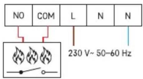
flowchart
graph TD
    A["OT"] --> C["SP Open Therm"]
flowchart
graph TD
    A["RT"] --> B["*1"]
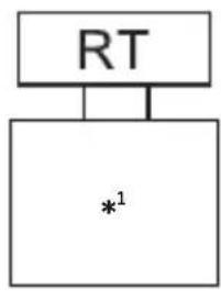
*¹ External temperature sensor 10K • Externí teplotní čidlo 10K • Vonkajší teplotný senzor 10K • Czujni ktemperatury zewnętrznej 10K • Külső hőmérséklet-érzékelő 10K • Zunanji temperaturni senzor 10K • Senzor vanjske temperature 10K • Externer Temperatursensor 10K • Зовнішній датчик температури 10K • Senzor de temperatură externă 10K • Išorinis temperatūros jutiklis 10K • Ārējais temperatūras sensors 10K • Välistemperatuuri andur 10K • Външен температурен сензор 10K • Capteur de température externe 10K • Sensore di temperatura esterna 10K • Externe temperatuursensor 10K • Sensor de temperatura externa 10K • Sensor de temperatura externo 10K • Εξωτερικός αισθητήρας θερμοκρασίας 10K • Extern temperatursensor 10K • Ulkoinen lämpötila-anturi 10K • Ekstern temperatursensor 10K
flowchart
graph TD
    A["*²"] --> B["NO"]
    B --> C["COM"]
    C --> D["L"]
    D --> E["N"]
    E --> F["N"]
    F --> G["N 230 V~50-60 Hz\nL 16 (5) A"]
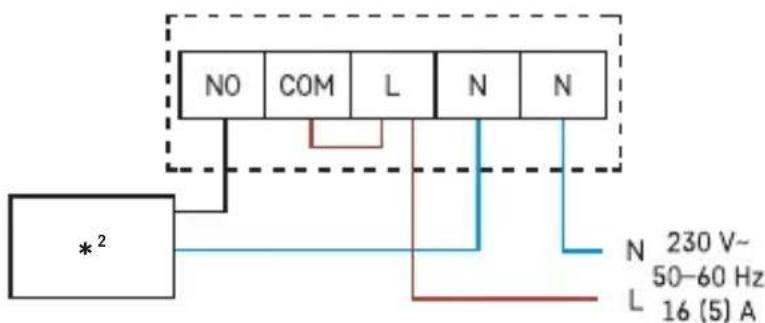
*2 Pump/valve • čerpadlo/ventil • čerpadlo/ventil • Pompa/zawór • Szivattyú/szelep • Črpalka/ventil • Pump (Pumpa)/Ventil • Pumpe/Ventil • Hacoc/ventil • Pompă/supapă • Siurblys/vožtuvas • Sūknis/vārsts • Pump/klapp • Pompa/klapan • Pompe/vanne • Pompa/ valvola • Bomba/válvula • Pomp/klep • bomba/válvula • αντλία/βαλβίδα • pump/ventil • pumppu/venttiili • pumpe/ventil
3
flowchart
graph TD
    A["*3"] --> B["NO"]
    A --> C["COM"]
    A --> D["L"]
    A --> E["N"]
    A --> F["N"]
    B --> G["N"]
    C --> H["L"]
    D --> I["N"]
    E --> J["N"]
    F --> K["N"]
    style A fill:#f9f,stroke:#333
    style B fill:#ccf,stroke:#333
    style C fill:#ccf,stroke:#333
    style D fill:#ccf,stroke:#333
    style E fill:#ccf,stroke:#333
    style F fill:#ccf,stroke:#333
    style G fill:#cfc,stroke:#333
    style H fill:#cfc,stroke:#333
    style I fill:#cfc,stroke:#333
    style J fill:#cfc,stroke:#333
*³ connected device • připojené zařízení • pripojené zariadenie • podłączone urządzenie • csatlakoztatott berendezés • priključena naprava • Priključeni uređaj • Angeschlossenes Gerät • підключення обладнання • dispozitiv conectat • prijungtas prietaisas • pievienota ierīce • ühendatud seade • свързано устройство • appareil connecté • dispositivi connessi • aparato conectado • aangesloten apparatuur • dispositivo conectado • συνδεδεμένη συσκευή • ansluten enhet • liitetty laite • tilsluttet enhed

flowchart
graph TD
    A["*⁴"] --> B["NO"]
    B --> C["COM"]
    C --> D["L"]
    D --> E["N"]
    E --> F["N"]
    F --> G["N 230 V~50-60 Hz"]
    style A fill:#f9f,stroke:#333
    style G fill:#bbf,stroke:#333
*4 Boiler • Kotel • Kotol • Kociot • Kazán • Kotel • Bojler • Kessel • Kotel • Cazan • Katilas • apkures katls • katel • kotel • chaudière • caldaia • caldera • ketel • caldeira • λέβητας • panna • kattila • kedel
6
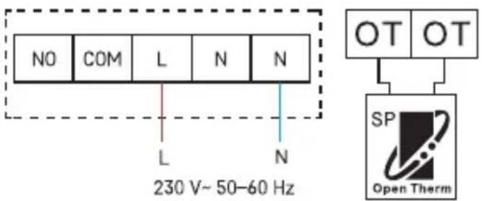
OT – OpenTherm connection • OT – OpenTherm prípojení • OT – OpenTherm pripojenie •
OT – podłączenie OpenTherm • OT – OpenTherm csatlakozó • OT – priključitev Opentherm
8
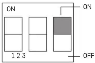
ON – heating | OFF – air-conditioning • ON – vytápění | OFF – klimatizace • ON – vykurovanie | OFF – klimatizácia • ON – ogrzewanie | OFF – klimatyzacja • ON – fútés | OFF – légkondicionáló • ON – ogrevanje | OFF – klima • ON – grijanje | OFF – klimatizacija • ON – Heizung | OFF – Klimatisierung • ON – опалення | OFF – кондиционер • ON – încălzire | OFF – climatizare • ON – šildymas | OFF – oro kondicionavimas • ON – apkure | OFF – gaisa kondicionēšana • ON – kütteseade | OFF – kliimaseade • ON (ВКЛ) — отопление | OFF (ИЗКЛ) — охлаждане • ON – chauffage | OFF – climatisation • ON – riscaldamento | OFF – aria condizionata • ON – calefacción | OFF – aire acondicionado • ON – verwarming | OFF – airconditioning • ON – aquecimento | OFF – ar condicionado • ON – θέρμανση | OFF – κλιματισμός • ON (PÅ) – värme | OFF (AV) – luftkonditionering • ON (PÄÄLLÄ) – lämmitys | OFF (POIS) – ilmastointi • ON – varme | OFF – aircondition
9
10
GB | Thermostat
Safety Instructions and Warnings

Read the user manual before using the device.

Follow the safety instructions in the manual.
- Read the manual carefully before using the product.
- Do not expose the product to direct sunlight, extreme cold and moisture, and sudden changes in temperature. These could reduce detection accuracy.
- Do not place the product in locations prone to vibration and shocks – may cause damage.
- Do not subject the product to extreme pressure, impacts, dust, high temperature or humidity – these could result in malfunction, shorter battery life, damage to batteries and deformation of plastic parts.
- Do not expose the product to rain or high humidity, or dropping or splashing water.
- Do not place any open flame sources on the product, e.g. a lit candle, etc.
- Do not put the product in places with inadequate air flow.
- Do not insert any objects into the product's vents.
- Do not tamper with the internal electrical circuits of the product – doing so may damage the product and will automatically void the warranty.
- The product should only be repaired by a qualified professional.
- Clean the product using a soft, slightly damp cloth. Do not use solvents or detergents – they might corrode the plastic parts and damage the electric circuits.
- Do not immerse the product in water or other liquids.
- In the event of damage or a defect on the product, do not perform any repairs by yourself. Bring it for repair to the shop where you bought it.
- Severe poisoning may occur within two hours of first issues appearing. Seek medical attention immediately.
- The appliance is not intended for use by persons (including children) whose physical, sensory or mental disability, or lack of experience and expertise prevents safe use, unless they are supervised or instructed in the use of the appliance by a person responsible for their safety. Children must always be supervised to ensure they do not play with the appliance.
Technical Specifications
Switched load: max. 230 V AC; 16 A for resistive load; 5 A for inductive load
Temperature measurement: 0 °C to 80 °C with 0.1 °C resolution; accuracy ±1 °C at 20 °C
Temperature setting: 7 °C to 30 °C in 0.2 °C increments
Temperature setting for floor sensor: 15 °C to 65 °C in increments of 0.2 °C
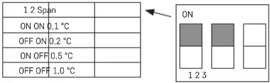
Temperature differential setting: 0.1 °C, 0.2 °C, 0.5 °C, 1.0 °C
Power supply: 230 V AC/50 Hz
Accessories: floor sensor 10k 3 m, 2 screws, 2 wall plugs
Dimensions and weight: 98 × 37 × 98 mm
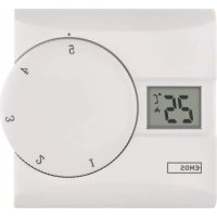
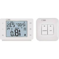
Thermostat Description (See Fig. 1)
1-day of the week
2-clock
3 - manual control
4-comfort mode (comfort temperature)
5 - economy mode (economy temperature)
6 – programme presets and temperature chart for the day
7 - set temperature
8-UPbutton
9 - DOWN button
10 – current room temperature
11 – low temperature protection mode
12 - operation icon (activation)
13 – time setting button
14 – comfort and economy temperature setting button
15 – programme setting button
16 – button for switching between comfort/economy mode
17 - contacts for connection
INSTALLATION
Warning:
Before the first use, make sure to carefully read the instruction manual for the thermostat, as well as the manual for the boiler or air-conditioning equipment.
Installation may only be carried out by a qualified professional!
Follow applicable standards during installation.
Before changing the thermostat, disconnect the heating system from the mains power in your home. This will prevent potential injury by electric current.
Installing the Thermostat (see fig. 2)
- Remove the rear cover of the thermostat (see fig. 2).
- Mark the spots for holes.
- Drill two holes, carefully insert the plastic wall plugs into them and use two screws to fasten the rear thermostat cover.
- Connect the wires to the labelled terminals according to the wiring diagram found under the cover.
- Complete the installation by fitting the thermostat onto the mounted rear cover.
Placement of the Thermostat
The placement of the thermostat significantly affects its functioning.
Choose a location where members of the family spend most of their time, preferably near an inside wall where air circulates freely, with no direct sunlight.
Do not place the thermostat in the vicinity of heat sources (such as TV sets, radiators, fridges), or close to a door.
Failure to comply with these recommendations will prevent proper control over room temperature.
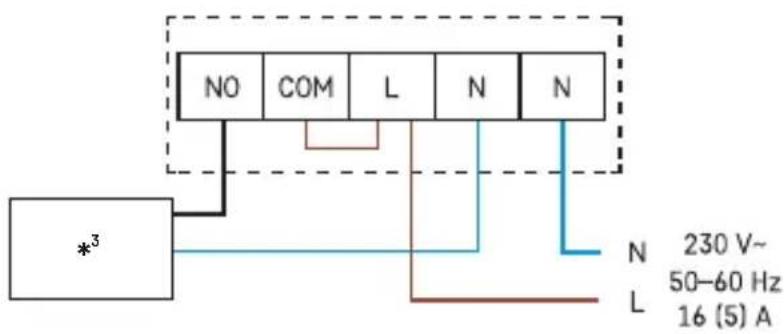
Wiring Diagram (See Fig. 3)
NO - normally open contact
COM - contact for the switch
L, N - phase, neutral (thermostat power supply)
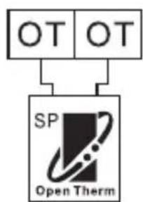
OT - OpenTherm connection
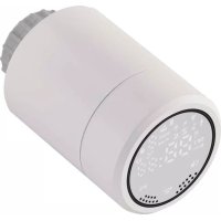
RT - floor sensor
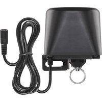
Pump/motorised valve connection diagram (see Fig. 4)
Floor heating connection diagram (see Fig. 5)
Boiler connection diagram (voltage-free switching) (see Fig. 6)
- The pre-installed wire connector between COM and L will not be connected
OpenTherm connection diagram (see Fig. 7)
OT - OpenTherm connection
BASIC SETTINGS
Heating/Cooling System Selection (See Fig. 8)
- Remove the rear cover of the thermostat – the printed circuit board inside has 3 DIP switches (see fig. 3).
These 3 switches are used to adjust the temperature differential and switch between the heating/cooling system.
- Set the DIP switch (position 3) depending on your choice of heating or cooling system (see fig. 9).
Selecting Temperature Differential
The temperature differential (hysteresis) is the difference in temperature required for the system to switch on and off. If, for example, you set the temperature in the heating system to 20 °C and differential to 0.2 °C, the thermostat activates heating as soon as room temperature drops to 19.8 °C and switches heating off when temperature reaches 20.2 °C.
Set the DIP switches (positions 1 and 2) depending on your choice of temperature differential (see fig. 10).
Note: Remember that the first pressing of a button activates display backlight, the next pressing sets values/functions.
Setting the Day/Time
Press the button. The day number will start flashing (1 – Monday to 7 – Sunday).
Use the + and - buttons (holding the button speeds up setting) to set the current day and press ⏻.
Set the hour, then press ⏻ again and set the minutes.
Confirm by pressing ⏻ or wait 15 seconds for the setting to save automatically.
Screen Illumination
Pressing any button will illuminate the screen for 10 seconds.
Setting Temperature
- Press the button to switch to temperature setting mode. The temperature value will start flashing.
- Repeatedly press the ⚙/¢ button to switch between setting the temperature for economy mode (¢ icon) and temperature for comfort mode (¢ icon).
- Use the or button to set both temperatures in 0.2 °C increments.
- Use the √ button to save the setting.
If no button is pressed for 10 seconds, setting mode ends automatically.
The preset comfort temperature is 21 °C for the heating system and 23 °C for cooling,
the preset economy temperature is 18 °C for the heating system and 26 °C for cooling.
Values can be changed, as necessary.
Setting a Programme
Selecting Week/Day
- Press the „P“ button; the day indicator will start flashing.
- Repeatedly press the + or - button to select the day you wish to programme.
You can choose to programme: days individually / workdays (1, 2, 3, 4, 5) / weekend (6, 7) / whole week (1, 2, 3, 4, 5, 6, 7).
Once you have chosen the days, continue by selecting a preset programme.
Selecting a Preset Programme
Press the „P“ button again to select a preset programme.
Use the + or - button to select one of the programmes: P1-P6. These programmes are factory presets (cannot be modified) and their profiles are shown in the figure.
Press the „P“ button again to confirm the selected programme for the given day/week and exit the setting mode.
| Programme Number | Programme profile of the day: 24 h;resolution: 1 hour |
| Programme 1:Comfort temperature all day | 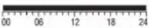 |
| Programme 2:Economy temperature all day | 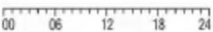 |
| Programme 3:Combination of comfort temperatureand economy temperature | 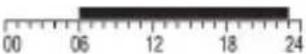 |
| Programme 4:Combination of comfort temperatureand economy temperature | 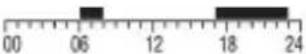 |
| Programme 5:Combination of comfort temperatureand economy temperature | 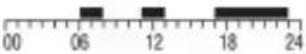 |
| Programme 6:Combination of comfort temperature and economy temperature | 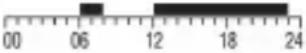 |
| Programme 7:Custom | 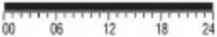 |
| Programme 8:Custom | 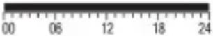 |
| Programme 9:Custom |  |
Dark bars indicate comfort mode settings, otherwise the thermostat is set to economy mode 00 06.
Setting a Custom Programme
- If you select a custom programme (P7, P8, P9) during programme selection, press the „P“ button to access temperature mode settings for the chosen period.
- Press the + or - button repeatedly to choose the hour, which is indicated by the flashing of the ■con.
Press ⚙/℃ to choose whether you want the system to be set to comfort or economy mode at that time.
- After you have set the profile for the entire day, press the „P“ button to confirm the selected programme and exit the setting mode.
Temporary Change of a Set Programme
In standard mode, where temperature is controlled by a selected programme, you can press the ⏻/C button to temporarily switch the current mode setting to comfort or economy mode.
When the selected programme is switched over in this way, the icon is displayed together with the selected control mode icon.
This setting will cancel automatically upon the next temperature change in the programme.
Temporary Change of Temperature Setting
In standard mode, where temperature is controlled by a selected programme, you can press the + or - button to override the current temperature setting. The newly set temperature will
be displayed along with the icon, the and icons will not be displayed. Pressing any button (except + or -) exits the temperature setting mode. If no button is pressed for 10 seconds, setting mode ends automatically. This setting will cancel automatically upon the next temperature change in the programme.
Note: If you wish to use the manually changed temperature for an extended period of time, we recommend doing so in programme no. 1 or 2.
Room Temperature Calibration
Long-press the „P“ button. CAL will appear on the screen and the set temperature value will be flashing.
Press + or – repeatedly to adjust the value (-3.0 °C to 3.0 °C, in 0.5 °C increments).
Press the „P“ button to confirm the setting.
Calibration of room temperature is used, for example, if the thermostat displays 21 °C but you want it to display 20 °C. In that case, the calibration value should be set to -1 °C.
Setting Button Sound
Long-press the „P“ button, then short-press the „P“ button again; the display will show „bEEP“.
Press the + or - button repeatedly to:
Activate button sound - ON
Deactivate button sound - OFF
Selecting the temperature sensor/Setting the temperature protection for the floor sensor
Press and hold the 'P' button, then press the "P" button twice quickly. 'SEN' will appear on the display.
Press the + or - button repeatedly for:
Internal sensor - IN
Floor sensor - OUT
Internal and floor sensor - ALL
If you have selected ALL, confirm by pressing the 'P' button and 'FL' will appear – floor sensor temperature protection.
Press the + or - button repeatedly to set the value (20 °C to 65 °C, in 1 °C increments).
If the set value is exceeded, the thermostat relay will switch off.
Note: If no floor sensor is connected and you select OUT or ALL, 'E2' will appear on the display.
Resetting the Thermostat
Long-press the „P“ button, then short-press the „P“ button 3×; the display will show „rESE“.
Press the ⏻ button 2×; the thermostat will reset to factory settings.
Antifreeze Mode
- Antifreeze mode is activated by pressing and holding the + and - buttons simultaneously for approx. 5 seconds (applies to heating mode only).


appear on the screen and and will not be displayed.
-
Default temperature for antifreeze mode is 7 °C.
-
Pressing any button cancels antifreeze mode.
Key Lock
Simultaneously hold the Ⓜ and + buttons for approx. 5 seconds.
All buttons will be locked and the thermostat screen will flash LOC on the top left.
To unlock the thermostat, press the ⏻ and + buttons simultaneously again for approx. 5 seconds; UNLO will flash on the screen.
Setting OpenTherm Parameters
Applies only to heating mode.
-
Long-press the √ button to access OpenTherm parameters. „01“ will appear in the left corner and water temperature in the OpenTherm boiler will appear in the centre (if the thermostat is not receiving a temperature reading, „--“ will be displayed instead).
-
Press the / button. „02“ will appear in the left corner of the screen and the temperature of the water returning back to the boiler will appear in the centre (if the thermostat is not receiving a temperature reading, „--“ will be displayed instead).
-
Press the √ button. „03“ will appear in the left corner and the temperature of hot water will appear in the centre (if the thermostat is not receiving a temperature reading, „--“ will be displayed instead).
-
Pressing the / button opens settings for temperature limit switching values. "04" will appear in the left corner and OFF will start flashing in the centre of the screen. Use + or - to select ON/OFF.
-
If you selected ON in the previous step, pressing / opens settings for the maximum temperature limit switching value. „05“ will appear in the left corner and temperature
will appear in the centre. You can adjust the temperature using the + and - buttons (30 to 80 °C in 1 °C increments).
- Pressing / opens settings for hot water switching. „06“ will appear in the left corner and OFF will start flashing in the centre of the screen. Use + or - to select ON/OFF.
- If you selected ON in the previous step, pressing / opens settings for hot water temperature. „07“ will appear in the left corner and temperature will appear in the centre. You can adjust the temperature using the + and - buttons (25 to 65 °C in 1 °C increments).
- Pressing opens the control switching settings. „08“ will appear in the left corner and ON will start flashing in the centre of the screen. Use + or - to select ON/OFF.
- Press the „P“ button to confirm the setting.
OpenTherm Error Indication
If an error occurs in the OpenTherm boiler, an „Exxx“ error code will appear on the screen, where „xxx“ is between 0 and 255.
Troubleshooting FAQ
The thermostat is not working
- check that all cables are intact and correctly connected.
- check that the OpenTherm setting is configured correctly on both devices.
- check that the target temperature on the thermostat is set correctly. If the temperature set on the thermostat is lower than current temperature in the room, the boiler or heating will not activate
- check that the heating/cooling mode is set correctly
- restart the thermostat
E2 is displayed on the screen
- the floor sensor is not connected – connect it
CZ | Termostat
OT - OpenTherm connection
RT – talni senzor
OT - OpenTherm connection
RT - Bodensensor
OT - OpenTherm connection
OT - OpenTherm connection
RT – senzor de podea
Schema de conectare a pompei/supapei motorizate (vezi fig. 4)
OT - OpenTherm connection
OT - OpenTherm connection
RT - vloersensor
12 - driftsymbol (aktivering)