P56211 - Thermostat Emos - Free user manual and instructions
Find the device manual for free P56211 Emos in PDF.

| Product type | Programmable wireless thermostat |
| Brand and model | Emos P56211 |
| Category | Room thermostat |
| Dimensions (control unit) | 40 × 138 × 96 mm |
| Dimensions (switching unit) | 37 × 86 × 86 mm |
| Power supply (transmitter) | 5 V / 1.5 A via micro USB (adapter included) |
| Power supply (receiver) | 230 V AC / 50 Hz |
| Temperature measurement range | 0 °C to 40 °C |
| Measurement accuracy | ±1 °C at 20 °C |
| Temperature setting range | 5 °C to 35 °C (step 0.5 °C) |
| Adjustable hysteresis | 0.2 °C to 2 °C (step 0.1 °C) |
| Radio communication frequency | 868 MHz (25 mW e.r.p. max.) |
| Built-in WiFi | 2.4 GHz (25 mW e.i.r.p. max.), 2.4 GHz only compatible |
| Wireless range (transmitter-receiver) | Up to 100 m in open space |
| Maximum switched load | 230 V AC, 16 A resistive / 4 A inductive |
| Display | LCD screen with backlight (15 s) |
| Thermal modes | Automatic, Manuals (Hold, Temporary, Boost), Holiday, Frost protection (OFF) |
| Weekly programming | Up to 6 periods per day, 7 days, 5+2, 24h modes |
| App control | EMOS GoSmart mobile app (iOS/Android) |
| Key lock | Yes (from thermostat or app) |
| Maintenance | Clean with a slightly damp soft cloth; do not use solvents |
| Safety | Cut power before installation; installation by qualified personnel recommended |
| Package contents | Control unit, switching unit, bracket, USB adapter, micro USB cable, manual |
Frequently Asked Questions - P56211 Emos
User questions about P56211 Emos
0 question about this device. Answer the ones you know or ask your own.
Ask a new question about this device
Download the instructions for your Thermostat in PDF format for free! Find your manual P56211 - Emos and take your electronic device back in hand. On this page are published all the documents necessary for the use of your device. P56211 by Emos.
USER MANUAL P56211 Emos
3
natural_image
Simple line drawing of a rectangular cabinet or enclosure with two doors on the front panel (no text or symbols)1
natural_image
Line drawing of a portable electronic device with a screwdriver and ventilation slots (no text or symbols)2
natural_image
Line drawing of a device with a scroll and directional arrow indicating rotation (no text or symbols)345
natural_image
Technical line drawing of an electronic device casing with internal components and a screwdriver (no text or symbols)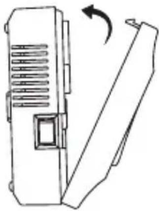
natural_image
Line drawing of a device with a scroll wheel and directional arrow (no text or symbols)4

15:20 春日
0% 94%
To provide you with better services, we request the following permissions:

natural_image
Illustration of a padlock with a lock and checkmark, surrounded by decorative elements (no text or symbols)When you use this App, we will collect necessary information (including statistical data, network usage data, application crash events) in order to monitor the performance of the App.

Data Analysis
Allow us to collect data-related to product usage. If you disable permissions, basic functions are still available.

Personalization
Allow us to recommend content through ads and notifications. If you disable it, we won't send what may interest you.
Go to App
III


8

9
GB | Wireless Thermostat
The P56211 wireless thermostat is designed for controlling heating and air-conditioning systems.
Important
Before the first use, make sure to carefully read the instruction manual for the thermostat, as well as the manual for the boiler or air-conditioning equipment.
Turn off power supply before installing the thermostat!
Installation should be carried out by a qualified person!
Follow applicable standards during installation.
Technical specifications:
Switched load: max. 230 V AC; 16 A for resistive load; 4 A for inductive load
Temperature measurement: 0 °C to 40 °C with 0.1 °C resolution; accuracy ±1 °C at 20 °C
Temperature setting: 5 °C to 35 °C in 0.5 °C increments
Temperature differential setting: 0.2 °C to 2 °C in 0.1 °C increments
Operating temperature: 0 °C to 40 °C
Unit interconnection: via 868 MHz radio signal, 25 mW e.r.p. max.
Transmitter unit range: up to 100 m in an open space
WiFi frequency: 2.4 GHz, max. 25 mW e.i.r.p.
Power supply:
Control unit (transmitter): 5 V/1.5 A
Switching unit (receiver): 230 V AC/50 Hz
Includes: USB adapter 5 V/1.5 A, micro USB cable 1.5 m
Dimensions:
Control unit: 40 × 138 × 96 mm
Switching unit: 37 × 86 × 86 mm
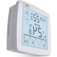
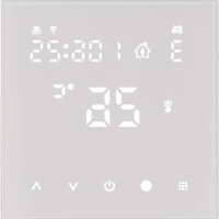
Description of the Thermostat (Transmitter Unit) – Icons and Buttons (see fig. 1)
1 - day number
2 - time
3 – WiFi signal reception
3.1 - wireless communication with receiver
4 - cooling /heating mode
5 - set temperature
6 - menu lock
7 - holiday mode
8 - temporary change of temperature
9 - HOLD mode
10 – current room temperature
11 – programme settings
12 – data and time settings
13 - function selection, confirmation
14 - temporary change of temperature; navigation in the settings
15 – return to main menu
Thermostat Stand (see fig. 2)
1 - micro USB socket for connecting the power cable
2 - removing the thermostat from the stand (start with the bottom of the thermostat first)
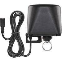
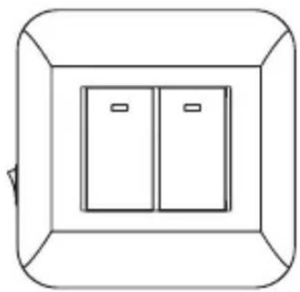
Description of the Receiver (Switching Unit) (see fig. 3)
1 - main switch
○ position - off
|position - on
2 - M/A button (red LED)
3 - MANUAL button (green LED)
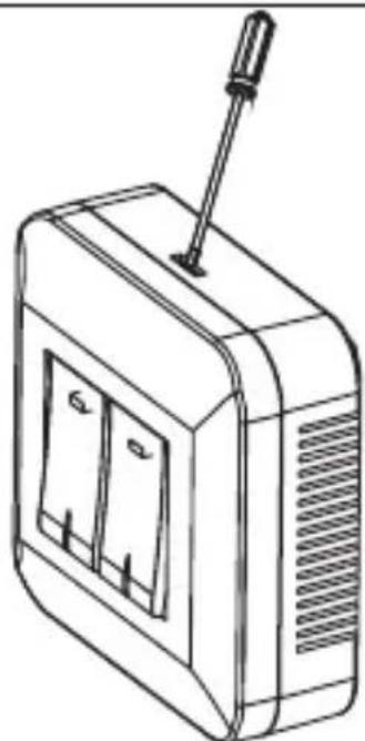
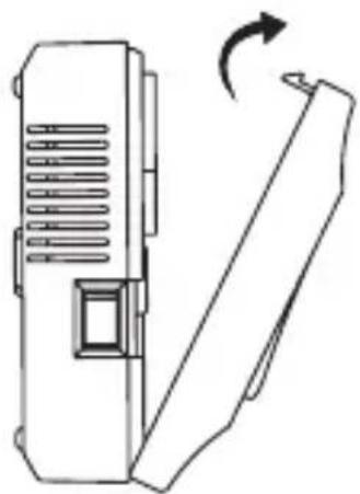
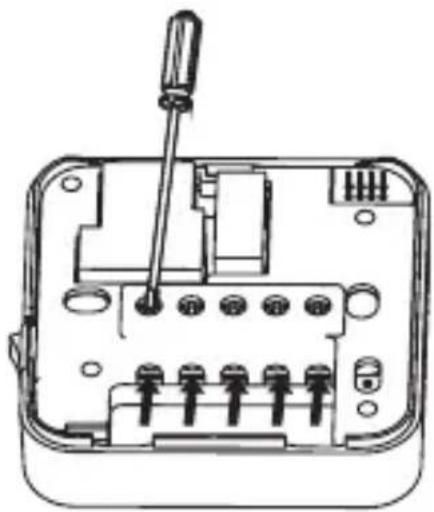
Procedure for Removing the Front of the Switching Unit (see fig. 4)
2, 3 - Use a screwdriver to press down and hold the inner lock, remove the front cover.
4, 5 - Connect the wires to the labelled terminals according to the wiring diagram, click the cover back in place.
Mobile Application
The thermostat can be controlled using a mobile application for iOS or Android.
Download the EMOS GoSmart app 📄 for your device.
QR code for downloading the Android app

QR code for downloading the iOS app

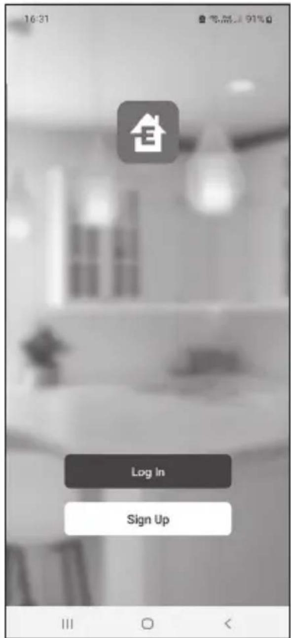
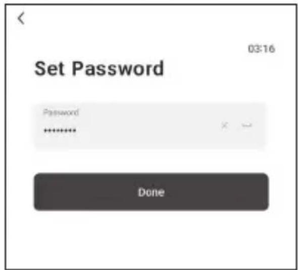
Description of Registering and Logging into the Application (see fig. 5)
To use the mobile application, you must first register by tapping the Sign Up button.
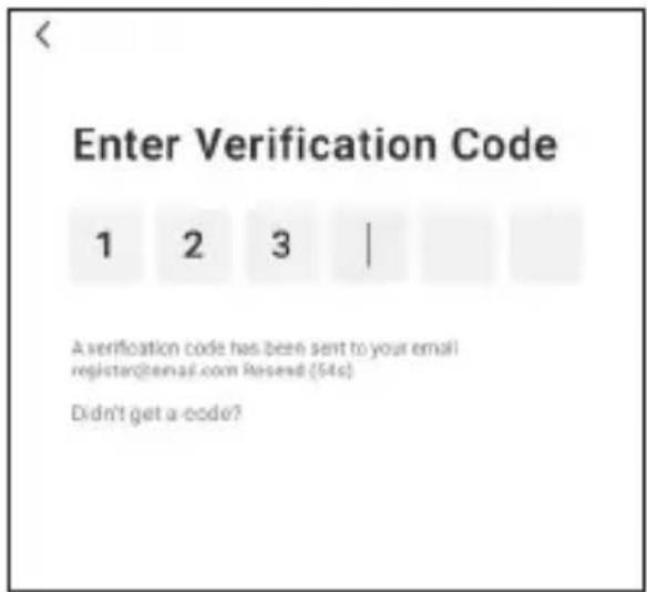
Enter your country and e-mail address, check off your consent with the end user licence agreement and tap Get Verification Code.
Enter the verification code sent to your e-mail.
Then, set the password for your account and tap Done.
Choose whether you want to enable Data Analysis/Personalisation and tap Go to App.
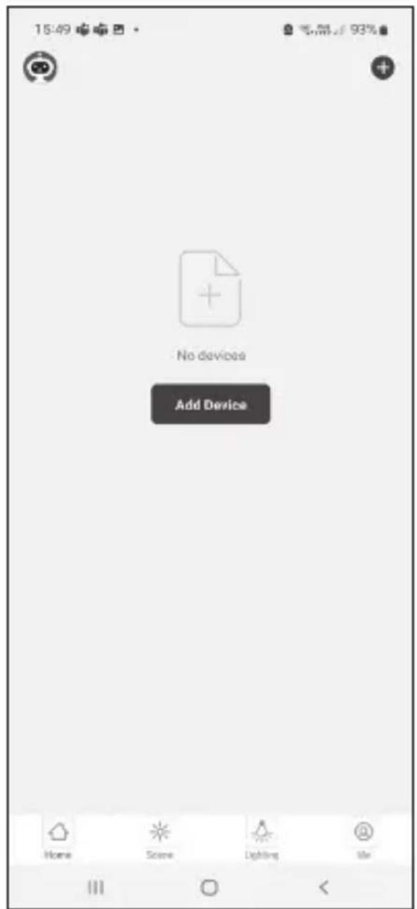
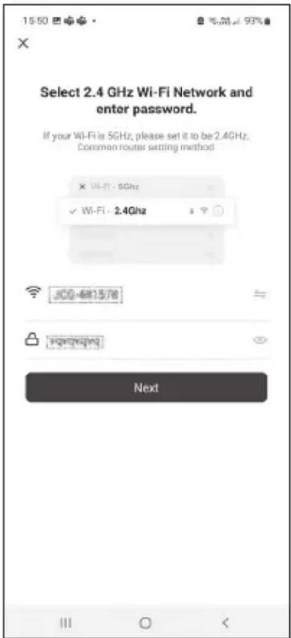
Connecting the Thermostat to a Wi-Fi network for Control via the Mobile App (see fig. 6)
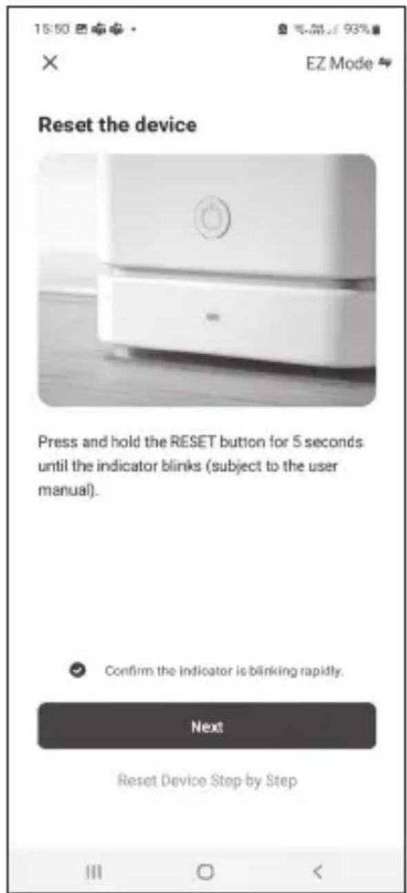
Long-press the button for about 5 seconds.
Then press and hold the ▶▶|button for 3 seconds.
E2 will appear on the screen and the icon will be flashing.
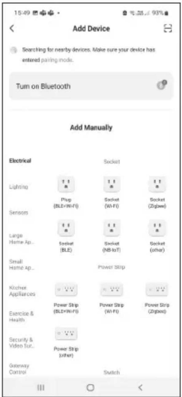
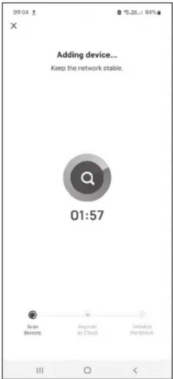
Tap Add Device in the app and enable location access.
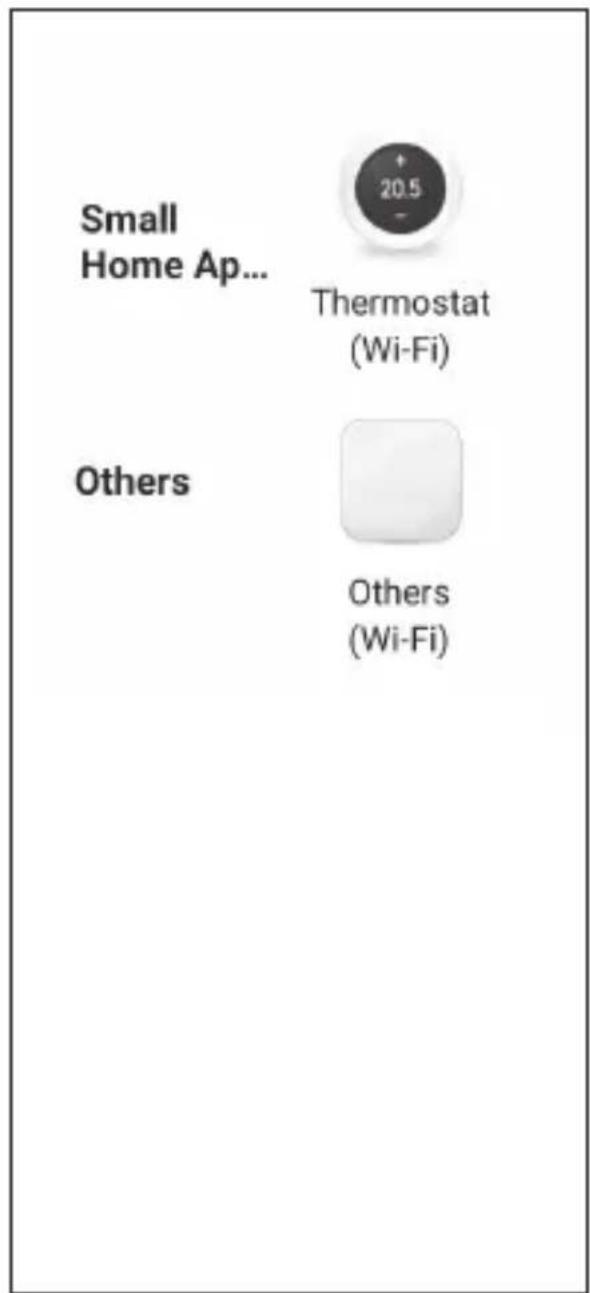
Choose add manually and select Small Home Appliances – Thermostat (Wi-Fi) or Others – Others (Wi-Fi).
Select a 2.4 GHz Wi-Fi network, enter the password and tap Next.
Check off Confirm that the indicator is flashing rapidly and tap Next.
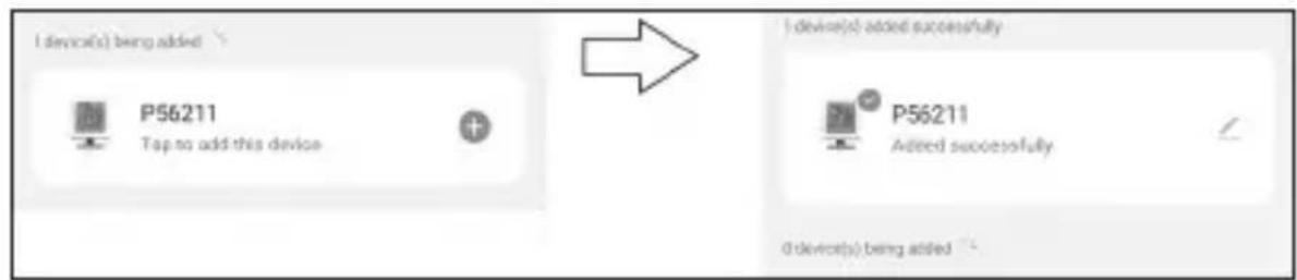
The chosen thermostat should appear in the app within 2 minutes.
Tap the green arrow on the right; the thermostat will be added into the app.
Then tap the thermostat icon in the app to open the main control menu.
Note:
If the thermostat fails to pair, repeat the process.
5 GHz Wi-Fi networks are not supported.
The thermostat can only be controlled via the app by 1 user at a time. If another user wants to control the thermostat, the previous user must log out.
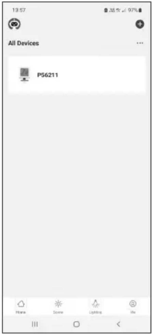
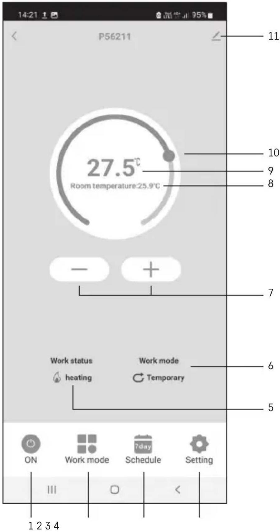
Description of the Main Menu of the Mobile App (see fig. 7)
Tap the thermostat icon in the app to open the main control menu.
- Thermostat status (ON/OFF) – Anti-freeze mode, temperature fixed to 5 °C
- Work mode setting (detailed information in the WORK MODES chapter of this manual)
Automatic
Manual – see HOLD mode
Temporary – see Temporary change mode
Boost – see Timed temporary change mode
Holiday – see Holiday mode
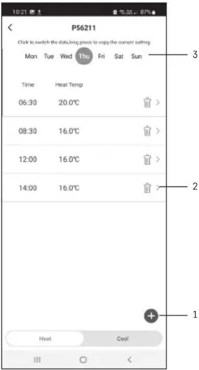
3. Schedule (see fig. 8)
1 - add a time period
2 – delete a time period
3-day display
7 days (Mon → Sun)
5+2 days (Mon → Fri + Sat → Sun)
24-hour
Every day can be divided into a maximum of 6 periods.
When in 7 day mode, you can copy the temperature settings from one day into other days (see fig. 9).
Example:
Long-press the Thursday icon; a menu of other days will open. Mark them orange by tapping them and confirm.
Thursday's schedule will copy over to Monday, Tuesday and Wednesday.
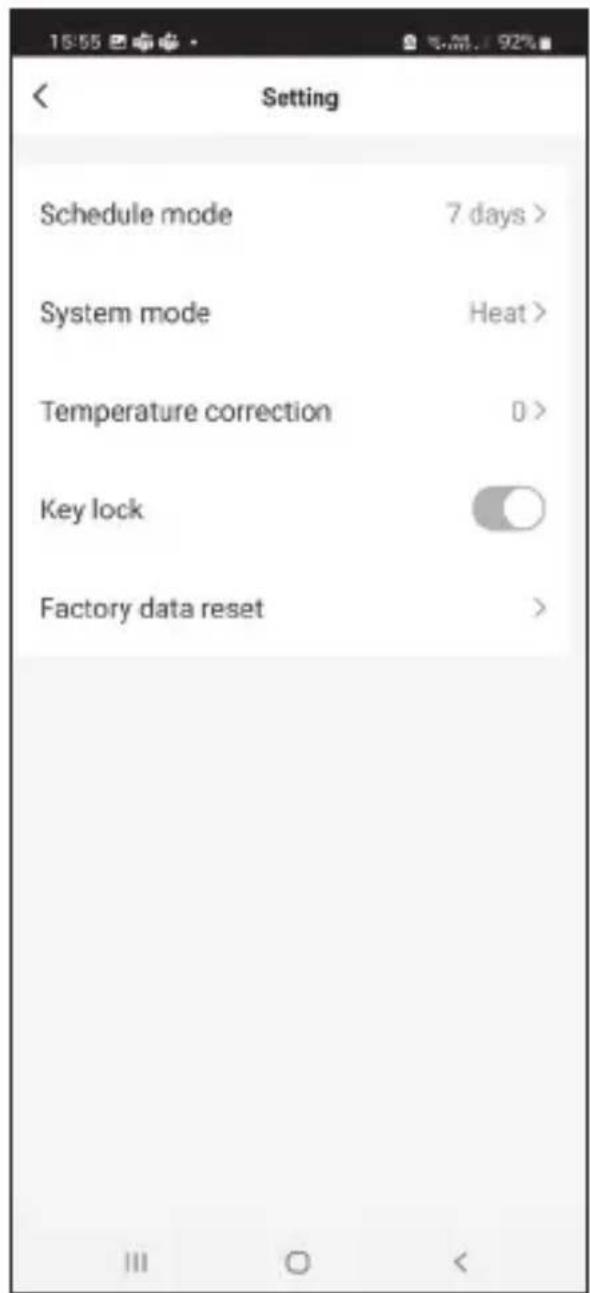
4. Setting (see fig. 10)
1 - reset the thermostat to factory settings
2 - key lock
3 - correction of ambient temperature (-3 °C to +3 °C in 0.5 °C increments)
4 – heating/cooling system mode
5 - calendar mode (7 days, 5+2, 24 h)
5. Thermostat mode icon
heating

cooling
off
- Work mode icon
- Adjust temperature
- Current room temperature
- Current set temperature
- Adjust temperature
- Network information about the device, change the name in the app, location information, add an icon to the home screen and other similar settings
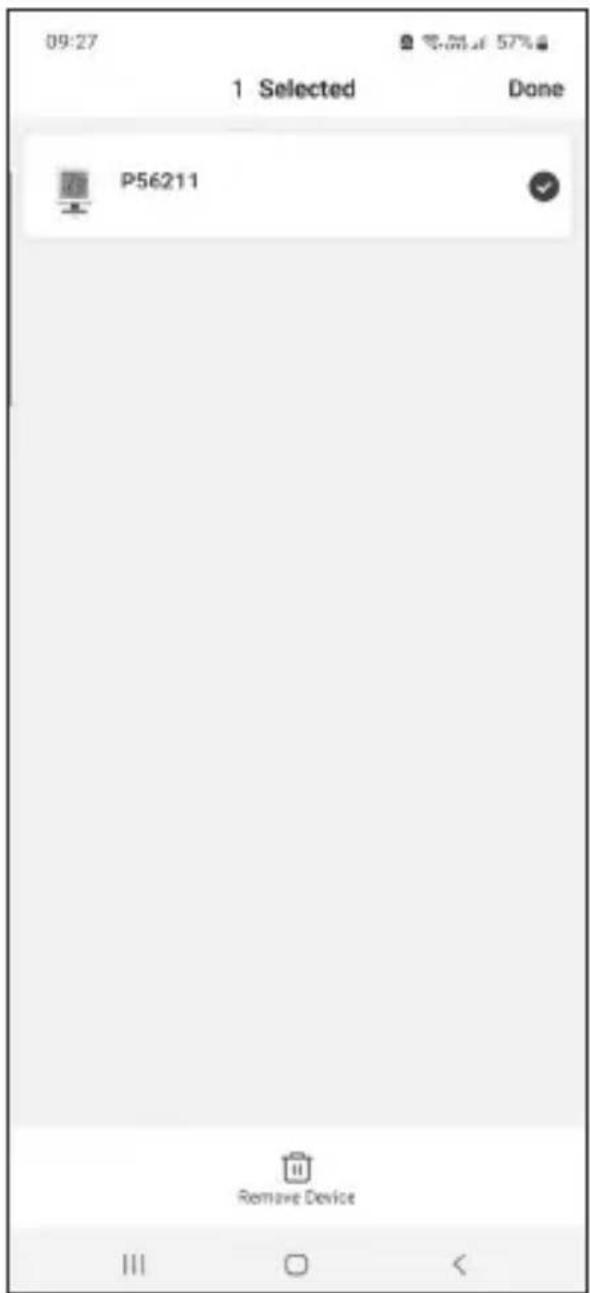
Deleting the Thermostat from the App (see fig. 11)
Long-press the thermostat icon, check off the thermostat and tap the dustbin icon to delete the thermostat.
User Overview/Password Change/App Update
Tap the icon in the bottom right and then the icon in the top right.
This will open a new menu with settings.
INSTALLATION
Attention:
Before changing the thermostat, disconnect the heating system from the mains power in your home. This will prevent potential injury by electric current.
Installing the Thermostat (see fig. 2)
Place the thermostat in the stand included in the pack.
Connect the USB power supply (included) with the connected micro USB cable to 230 V mains.
Plug the micro USB cable into the bottom of the stand.
Placement of the Thermostat
The placement of the thermostat (transmitter unit) significantly affects its functioning.
Choose a location where members of the family spend most of their time, preferably near an inside wall where air circulates freely, with no direct sunlight. Do not place the thermostat in the vicinity of heat sources (such as TV sets, radiators, fridges), or close to a door. Failure to comply with these recommendations will prevent proper control over room temperature.
Switching Unit Wiring Diagram
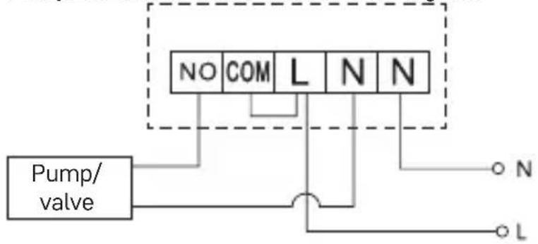
Pump/Motorised Valve Connection Diagram
flowchart
graph TD
    A["Pump/ valve"] --> B["NO"]
    A --> C["COM"]
    A --> D["L"]
    A --> E["N"]
    A --> F["N"]
    B --> G["O N"]
    C --> H["O L"]
    D --> I["O N"]
    E --> J["O L"]
    F --> K["O N"]
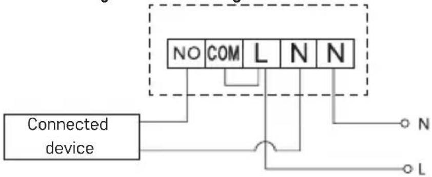
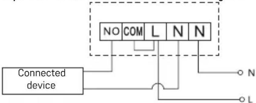
Floor Heating Connection Diagram
flowchart
graph TD
    A["Connected device"] --> B["NO"]
    A --> C["COM"]
    A --> D["L"]
    A --> E["N"]
    A --> F["N"]
    A --> G["L"]
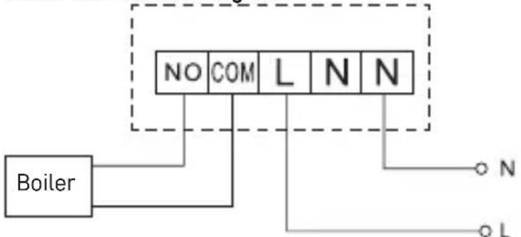
Boiler Connection Diagram
flowchart
graph TD
    Boiler["Boiler"] -->|NO| Grid1["Grid"]
    Boiler -->|COM| Grid2["Grid"]
    Boiler -->|L| Grid3["Grid"]
    Grid1 -->|N| Grid4["Grid"]
    Grid2 -->|N| Grid5["Grid"]
    Grid3 -->|N| Grid6["Grid"]
    Grid4 -->|N| Grid7["Grid"]
    Grid5 -->|N| Grid8["Grid"]
    Grid6 -->|N| Grid9["Grid"]
- The pre-installed wire coupler will not be connected.
Expansion Valve/Electric Drive Connection Diagram
flowchart
graph TD
    A["Connected device"] --> B["NO"]
    A --> C["COM"]
    A --> D["L"]
    A --> E["N"]
    A --> F["N"]
    B --> G["O N"]
    C --> H["O L"]
    D --> I["O N"]
    E --> J["O L"]
    F --> K["O N"]
Pairing the Control Unit with the Switching Unit
Both thermostat units must be paired before first use.
Pairing enables transmission of information between the control unit and the switching unit.
Setting is done via automated pairing (self-learning).
- Fit the thermostat gently onto the stand.
Connect the USB power supply with micro USB cable to 230 V mains and plug the cable into the stand.
- Correctly connect the switching unit to voltage supply, turn the main switch to the I position and long press (for at least 10 seconds) the M/A button; a green LED will begin flashing on the MANUAL button.
- Long-press the and buttons on the thermostat (transmitter) for about 5 seconds; the • icon will start flashing.
Both units will be paired within 1 minute and the green diode on the switching unit will stop flashing.
If you want to change the pairing code of the two units or the thermostat does not function properly, repeat the entire pairing procedure from step 1 – the pairing code will be rewritten automatically.
Testing Wireless Communication between the Units
- Use the button on the thermostat or use the app to set a temperature several degrees higher than the current room temperature.
- The red LED on the switching unit will light up.
- If the LED does not light up, move the control unit closer to the switching unit. The maximum range between the control and switching unit is 100 m in an open space.
The range may decrease indoors as the signal has to pass through walls and other obstacles.
Main Switch
To turn on the switching unit, set the switch to the | position.
If the heating system is not used for an extended period of time, it is recommended to turn the switching unit off (switch the main switch to the position).
LED Indicators
Automated Mode
In automated mode, a red LED will glow when the thermostat switches on the output relay.
Manual Mode
Press the MANUAL button; a green LED will light up.
The receiver will switch to manual mode and will not respond to commands from the thermostat.
To switch on the output relay (turn on the connected device), press the M/A button; a red LED will light up on it.
To turn off manual mode, press the MANUAL button again; the green LED will switch off.
Setting the Clock, Calendar
Press the button; the values will start flashing.
Use the ↗ buttons to set the following values (holding the button down accelerates the value change):
Day – Month – Year – Hour – Minute.
Confirm the set value by pressing ▶▶
To end setting, press the 📋 button or wait 30 seconds.
After setting is complete, the current day number will be displayed:
1 - Monday
2 - Tuesday
3 – Wednesday
4 – Thursday
5 – Friday
6 - Saturday
7 – Sunday
WORK MODES
Holiday Mode
Sets a constant temperature for an extended period of time.
Long-press (5 seconds) the ▶ button; the time value will start flashing.
Release the ▶ button and press it again for 5 seconds.
The I don will appear and the number of days will start flashing.
Repeatedly press the ^ button to set the number of days (from 1 to 99).
Confirm the set number of days by pressing ▶ the temperature value will begin flashing.
Repeatedly press the ^button to set the temperature.
Confirm by pressing ▶, the icp will appear.
If you want to go back and change the temperature for holiday mode, press the button repeatedly.
You can cancel holiday mode by pressing ▶ ▶ ▶ .
Temporary Change Mode
Short-term manual change of temperature.
While in Auto mode, use the ^buttons to change the temperature setting; the value will be saved automatically.
The icon will appear.
This mode will be automatically cancelled by the first programmed temperature change (the time remaining until the change + clock will be alternating in the top left corner) or it can be cancelled manually by pressing
OFF Mode
Anti-freeze mode, temperature fixed to 5 °C.
While in Auto mode, press the ▶▶| button 2×; a temperature of 5 °C will appear in the top right corner.
To cancel the mode, press
Timed Temporary Change Mode
Temporary manual change in temperature for 1 to 9 hours.
While in Auto mode, long-press the▶▶|button; the time setting will start flashing in the top left corner.
Use the ^ buttons to set the duration of the temperature change, from 1 to 9 hours, with 1 h resolution.
Confirm by pressing 📋 Then set the temperature of choice using the buttons.
The remaining set time + the clock will be alternating in the top left corner; you can cancel the mode prematurely by pressing 📂.
HOLD Mode
Permanent manual temperature change.
While in Auto mode, press the ▶▶ button; the HOLD will appear in the bottom right.
Set the temperature of choice using the ▲ buttons; the value will be saved automatically.
The set temperature will be maintained until HOLD mode is cancelled.
Any programmed temperature change will not be carried out.
To cancel HOLD mode, press
Heating Programme Setting Mode
Sets temperature over the course of the whole day (6 temperature changes in the day).
Press the PRG button. The day number will start flashing (1-7 = Monday to Sunday).
Press ^ repeatedly to select the days of choice.
Different each day programme – the number of the selected day flashes
Monday to Friday programme – 1 flashes 5
Saturday to Sunday programme – 67shes
All week programme - 1fastes 567
Select your programme of choice and confirm with ▶▶
The time of the first temperature change will be flashing; you can set the time by repeatedly pressing ∧(10 minute increments), then confirm with .
The temperature value will begin flashing; set by repeatedly pressing P1 will appear below the set temperature, indicating the 1st temperature change in the day.
Confirm by pressing ▶ Continue by setting the start of the second temperature change (P2 will appear under the temperature).
Set the time and temperature by following the same steps as when setting the 1st temperature change.
Continue the process until all 6 temperature changes (P1 to P6) are set.
Factory pre-set times and temperatures are as follows:
Monday to Friday
| Temperature change Time Temperature | ||
| P1 6:30 20 °C | ||
| P2 8:30 16 °C | ||
| P3 12:00 16 °C | ||
| P4 14:00 16 °C | ||
| P5 16:30 21 °C | ||
| P6 22:30 7 °C | ||
Saturday to Sunday
| Temperature change Time Temperature | ||
| P1 7:30 20 °C | ||
| P2 9:30 20 °C | ||
| P3 11:30 20 °C | ||
| P4 13:30 20 °C | ||
| P5 16:30 20 °C | ||
| P6 22:30 15 °C |
Screen Illumination
Pressing any button will illuminate the screen for 15 seconds.
Other Technical Settings
Long-press the button for about 5 seconds.
Repeatedly pressing the ▶ button selects from the functions below, values are adjusted using the ▶ buttons.
Connecting the Thermostat to WiFi (COFI)
Long-press the button for about 5 seconds.
Then press and hold the ▶ button for 3 seconds.
E2 will appear on the screen and the icon will be flashing.
Complete the pairing of the thermostat in the mobile app.
See instructions for Connecting the Thermostat to a WiFi Network for Control via the Mobile App.
Switching Heating/Cooling Mode
Long-press the button for about 5 seconds.
Press the ▶ button once.
Use the ^ buttons to switch to heating (HEAT) or cooling (COOL) mode.
Confirm with
Setting the Temperature Differential _d FF
The temperature differential (hysteresis) is the difference in temperature required for switching the system on and off. If, for example, you set the temperature in the heating system to 20 °C and the differential to 0.2 °C, the thermostat activates heating as soon as room temperature drops to 19.8 °C and switches heating off when temperature reaches 20.2 °C.
Long-press the button for about 5 seconds.
Press the ▶ button 2× and use the buttons to set the temperature differential value (0.2 °C to 2 °C in 0.1 °C increments).
Confirm with
Ambient Temperature Calibration (CAL)
The temperature sensor in the thermostat is calibrated from production, but additional calibration can be done to optimise the thermostat further, for instance by comparing the measured room temperature with a reference thermometer.
Long-press the 📋 button for about 5 seconds.
Press the ▶ button 3× and use the ∧ buttons to set the calibration value (-3 °C to +3 °C in 0.5 °C increments).
Confirm with
Time Synchronisation (SYNC)
Long-press the button for about 5 seconds.
Press the ▶ button 4× and use the buttons to set:
ON – time will be automatically synchronised with the Wi-Fi network;
OFF – time will not be synchronised with the Wi-Fi network and the time you set manually will be used.
Confirm with
Software Version
Long-press the button for about 5 seconds.
Press the ▶▶ button 5×; the software version of the thermostat will be displayed.
Return by pressing
Resetting the Thermostat (rESE)
Long-press the button for about 5 seconds.
Press the ▶▶ button 6×; rESE will appear on the screen.
Press the PRG button; -- -- will be displayed.
Press the PRG button again; the thermostat's menu will be reset and all set values will be deleted.
Key Lock
Long-press the PRG button for about 3 seconds.
All buttons will be locked, the thermostat will flash LOC in the top left of the screen and the screen will be displayed.
To cancel the lock, hold the PRG button again for about 3 seconds; UNLO will flash on the screen.
Setting the lock in the mobile app:
- lock activation, - lock deactivation
Attention:
If you activate the lock in the app, the lock can also be cancelled using the PRG button on the thermostat.
Upkeep and Maintenance
The product is designed to serve reliably for many years if used properly. Here are some tips for proper operation:
- Read the manual carefully before using the product.
- Do not expose the product to direct sunlight, extreme cold and humidity and sudden changes in temperature. This would reduce measuring accuracy.
- Do not place the product in locations prone to vibration and shocks – may cause damage.
- Do not subject the product to excessive force, impacts, dust, high temperatures or humidity – doing so may cause malfunction, shorten battery life, damage batteries and deform plastic parts.
- Do not expose the product to rain or high humidity, dropping or splashing water.
- Do not place any open flame sources on the product, e.g. a lit candle, etc.
- Do not put the product in places with inadequate air flow.
- Do not insert any objects into the product's vents.
- Do not tamper with the internal electrical circuits of the product – doing so may damage the product and will automatically void the warranty. The product should only be repaired by a qualified professional.
- To clean the product, use a slightly moistened soft cloth. Do not use solvents or cleaning agents – they could erode the plastic parts and cause corrosion of the electric circuits.
- Do not immerse the product in water or other liquids.
- In the event of damage or defect of the product, do not perform any repairs by yourself. Have it repaired in the shop where you bought it.
- This device is not intended for use by persons (including children) whose physical, sensory or mental disability or whose lack of experience or knowledge prevents them from using it safely. Such persons should be instructed in how to use the device and should be supervised by a person responsible for their safety. Children must always be supervised to ensure they do not play with the device.
ATTENTION: The contents of this manual may be changed without prior notice – due to printing limitations, the symbols shown may differ slightly from those on the screen – the content of this manual may not be reproduced without the manufacturer's permission.

Do not dispose with domestic waste. Use special collection points for sorted waste. Contact local authorities for information about collection points. If the electronic devices would be disposed on landfill, dangerous substances may reach groundwater and subsequently food chain, where it could affect human health.
Hereby, EMOS spol. s r. o. declares that the radio equipment type P56211 is in compliance with Directive 2014/53/EU. The full text of the EU declaration of conformity is available at the following internet address: http://www.emos.eu/download.
(7 days) 7 dnǚ (Po → Ne)
(5+2 days) 5+2 (Po → Pá + So → Ne)
(5+2 days) 5+2 (Po → Pia + So → Ne)
(5+2 days) 5+2 (Pon → Pt + Sob → Niedz)
Opis registracije in prijave v aplikacijo (glej sliko 5)
Za uporabo mobilne aplikacije je treba, da se najprej registrirate s klikom na tipko Registiraj se.
(7 days) 7 dni (Pon → Ned)
(5+2 days) 5+2 (Pon → Pet + Sob → Ned)
(24 ur) 24-urni
2 - Gumb M/A (crveni LED)
3 - Gumb MANUAL (zeleni LED)
Postupak za uklanjanje prednjeg dijela sklopne jedinice (pogledajte sl. 4)
2, 3 – Koristite odvijač da biste pritisnuli i držali unutarnju zakačku, uklonite prednji poklopca.
4, 5 – Spojite žice na označene priključke prema shemi ožičenja, pritisnite poklopac natrag na mjesto.
Mobilna aplikacija
Opis registracije i prijave u aplikaciju (pogledajte sl. 5)
Da biste koristili mobilnu aplikaciju, prvo se morate registrirati pritiskom na gumb Registracija.
5+2 dana (pon → pet + sub → ned)
24-satni oblik prikaza vremena
(7 days) 7 Tage (Mo → So)
(5+2 days) 5+2 (Mo → Fr + Sa → So)
(24 hour) 24stunden
(7 days) 7 jours (Lun → Dim)
(5+2 days) 5+2 (Lun → Ven + Sam → Dim)
(24 hour) 24 heures
Voyants LED (diodes)
Mode automatique
(7 days) 7 giorni (Lun → Dom)
(5+2 days) 5+2 (Lun → Ven + Sab → Dom)
(24 hour) 24 ore
Interruptor principal
QR-code om de iOS-app te downloaden

(7 days) 7 dagen (Ma → Zo)
(5+2 days) 5+2 (Ma → Vr + Za → Zo)
(24 hour) 24 uur
Programma Hele week – knippert 1234567