P5630S - Thermostat Emos - Free user manual and instructions
Find the device manual for free P5630S Emos in PDF.

User questions about P5630S Emos
0 question about this device. Answer the ones you know or ask your own.
Ask a new question about this device
Download the instructions for your Thermostat in PDF format for free! Find your manual P5630S - Emos and take your electronic device back in hand. On this page are published all the documents necessary for the use of your device. P5630S by Emos.
USER MANUAL P5630S Emos
natural_image
Technical line drawing of a cylindrical mechanical component with a flanged end (no text or symbols)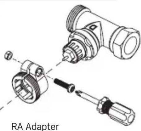
A
natural_image
Illustration of a hand holding a cylindrical device with a grid-patterned body, emitting light (no text or symbols)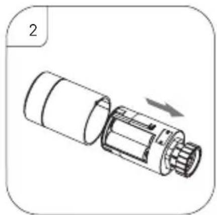
natural_image
Technical illustration of a mechanical component with an arrow indicating direction (no text or symbols present)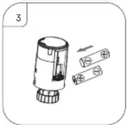
natural_image
Diagram of a cylindrical device with internal components and two separate cylindrical parts, no text or symbols present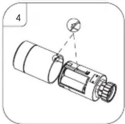
natural_image
Diagram of a mechanical device with a magnified inset showing a circular component (no text or symbols)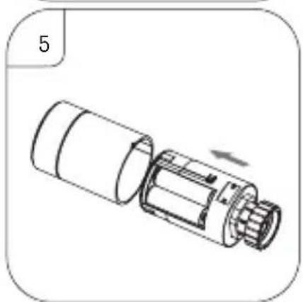
natural_image
Technical illustration of a mechanical component with no visible text or symbols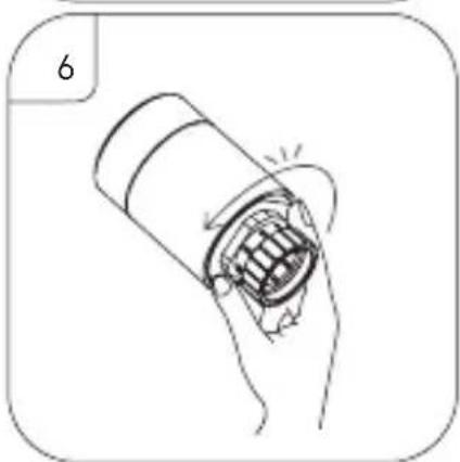
natural_image
Illustration of a hand holding a cylindrical object with a grid pattern, no text or symbols present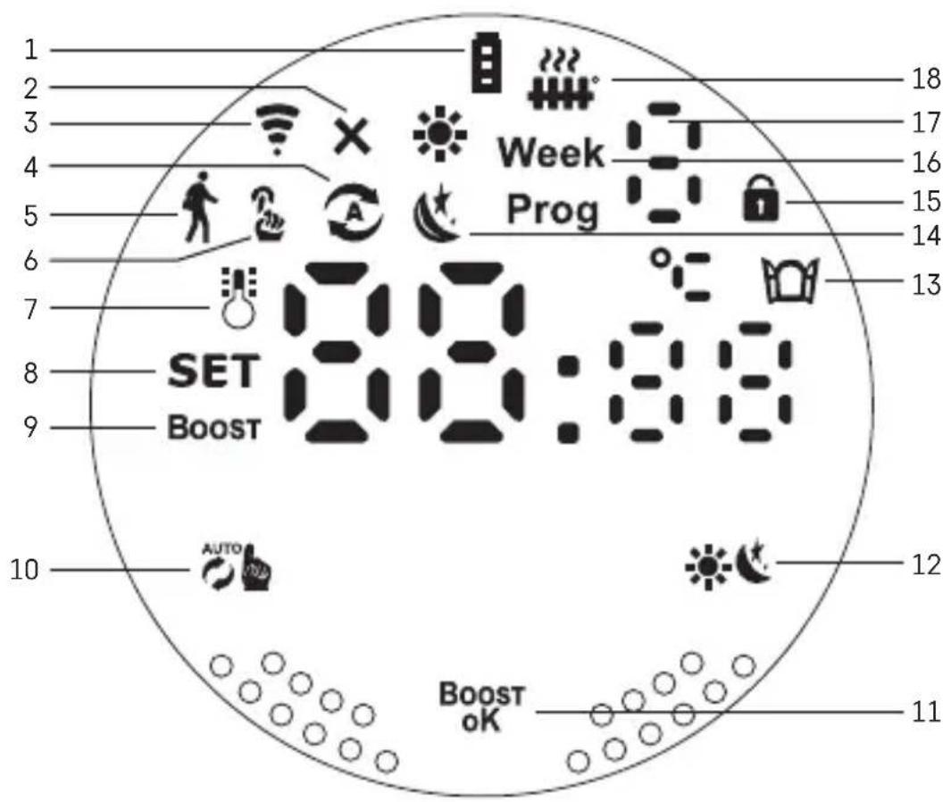
C
1
2
3
4
5
6
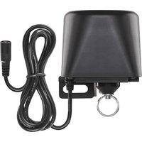
GB | Thermostatic Radiator Valve
Specifications
Temperature control range: 5 °C – 35 °C, 0.5 °C resolution
Range of displayed temperature: 1 °C – 70 °C, 0.5 °C resolution
Power supply: 2× 1.5 V AA
Maximum current draw: 90 mA
Maximum valve lift: 4.5 mm
Mounting dimensions of the head: M30 × 1.5
Operating temperature: -10 °C to 60 °C
Installation
-
The head is designed for all types of commonly available radiator valves without the need to interrupt heat circulation. If the thermostatic head is not compatible, proceed in accordance with information provided in the Compatibility section.
-
Place batteries into the head before installing. Remove the old thermostatic head by loosening the nut on the radiator head. Fit the head on the front and manually tighten the nut.
Note:
- The head support must connect in the middle to the support on the head.
- The head must not be compressed or wedged.
- Make sure the screen is visible and legible in the mounted position.
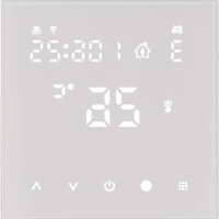
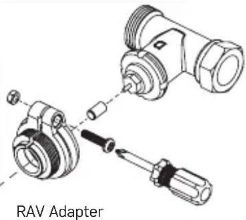
Compatibility (see fig. A)
The head may not be compatible with certain radiator heads.
Please compare your head with information provided by the manufacturer and use a suitable adapter if needed.
Enclosed adapters: Danfoss RA, RAV, RAVL
Mount the adapter onto the head and turn it until it clicks in place.
Fasten the adapter with a screw, if the adapter is designed for it.
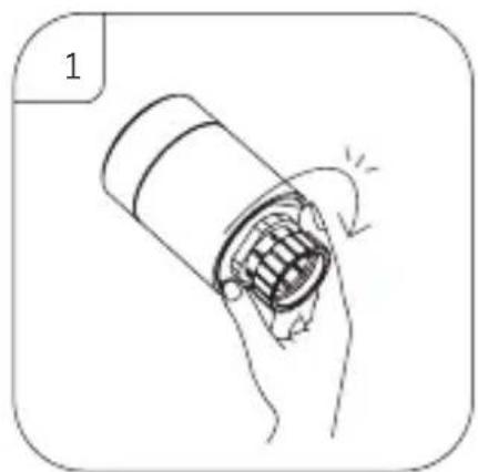
Inserting/Changing the Batteries (see fig. B)
- Grab a hold of the square section of the head located below the thread. Turn the square section clockwise. You should hear the head's lock release after turning.
- Slide the inner core of the head from the housing.
- Replace the batteries. Make sure to observe the correct polarity.
- Find the arrow icon on the housing and the slide slot on the inner core.
- Slide the core back into the housing.
- Once the core is all the way in, grab a hold of the square bottom portion of the head located below the thread and turn the inner core of the head counter-clockwise. You should hear the head's lock close after turning.
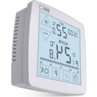
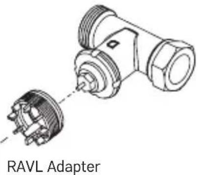
Description of the Screen of the Thermostatic Head (see fig. C)
1 – Low battery indicator
Starts flashing once the batteries are nearly depleted.
2 – Indication of connection status to Zigbee gateway ✗. Indicator on – not connected. Indicator off – connected.
3 - Connection signal strength icon
4 - Weekly mode icon Ⓐ.
Indicator on – the mode is active. Indicator off – the mode is inactive.
5 – Holiday mode icon 🍒.
Indicator on – the mode is active. Indicator off – the mode is inactive.
6 - Manual mode icon
Indicator on – the mode is active. Indicator off – the mode is inactive.
7 – If the icon is lit up, the screen shows the current temperature in the room.
8 – If lights up, the screen shows the temperature in the mode you have set.
9 – The Boost means the mode is active.
10 - Button for switching between weekly mode and manual mode
11 - Confirmation button and button for turning Boost mode on or off
12 - Button for switching between comfort and ECO mode.

13 – Icon for the open window function 📄. Indicator on – the head detects an open window and activates the function.
14 - Comfort or ECO mode active.
15 – Child lock icon 🔒.
16 – The Week indicates that you need to input the current time. The Prog icon indicates which time period of your weekly mode is currently active.
17 – The number of the currently active time period in weekly mode:
18 – The icon indicates movement and status of the valve. If flashing, the valve is closing/opening. If the valve is open, the icon stays lit. Once the valve closes, the icon turns off.
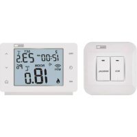
Basic Settings
- Mount the thermostatic head onto the radiator and insert the batteries.
- Install the EMOS GoSmart app from Google Play/App Store onto your phone.
- Connect the thermostatic head to your Zigbee gateway which is connected to the EMOS GoSmart app in line with the following instructions.
Instructions for Connecting the Thermostatic Head to the Zigbee Gateway
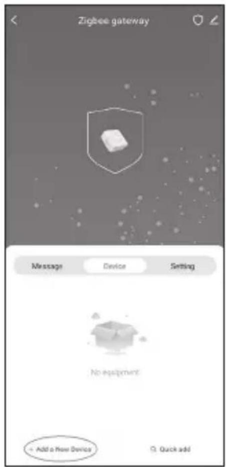
- Click the „+ Add a New Device“ button in the settings of your Zigbee gateway (see fig. 1).
-
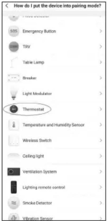
Find „Thermostat“ in the list of devices (see fig. 2).
-
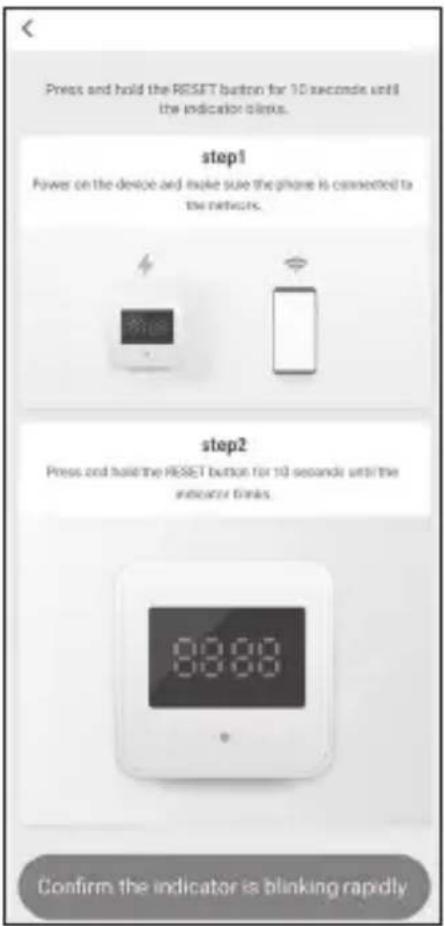
Simultaneously hold 📋 "Weekly/Manual" and 🔊 Comfort/ECO" buttons on the thermostatic head for 5 seconds (see the Description of the Screen in the previous section of the manual). Confirm that the icon for connection to the Zigbee gateway is flashing rapidly on the head (see fig. 3).
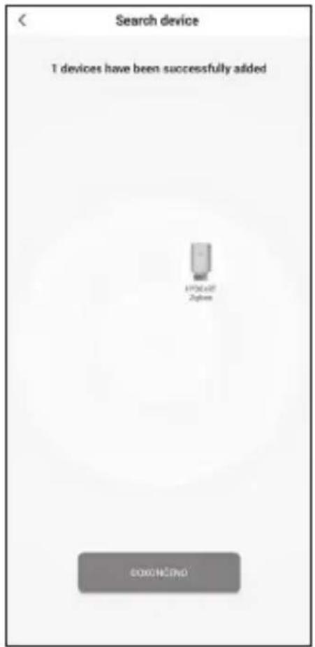
-
The Zigbee gateway should detect the thermostatic head in a few moments. Once it does, tap the „Done“ button (see fig. 4).
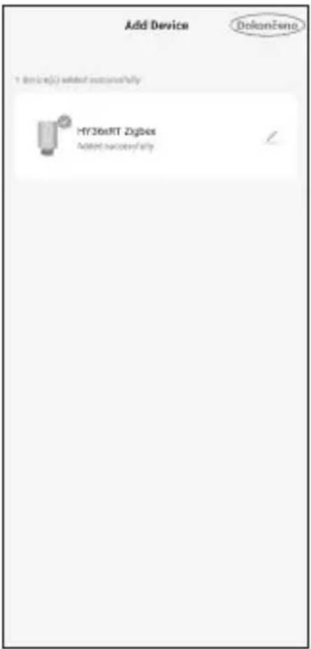
-
After confirming the previous step, your phone will ask for confirmation to add the thermostatic head to your GoSmart app. Continue by tapping „Done“ (see fig. 5).
-
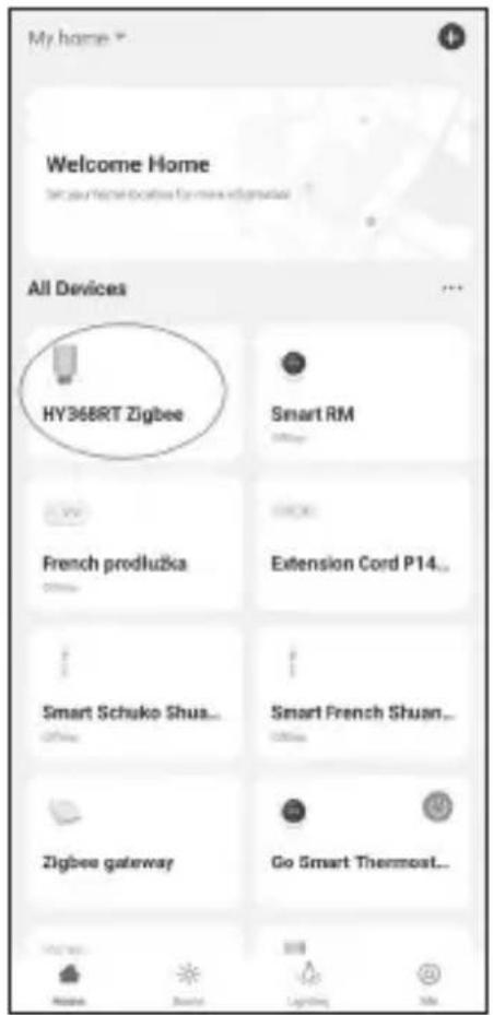
Once you tap „Done“, you will be redirected to the main screen of your GoSmart app, where the paired thermostatic head will already be available (see fig. 6).
Setting the Thermostatic Head
- The thermostatic head can be set using the EMOS GoSmart app.
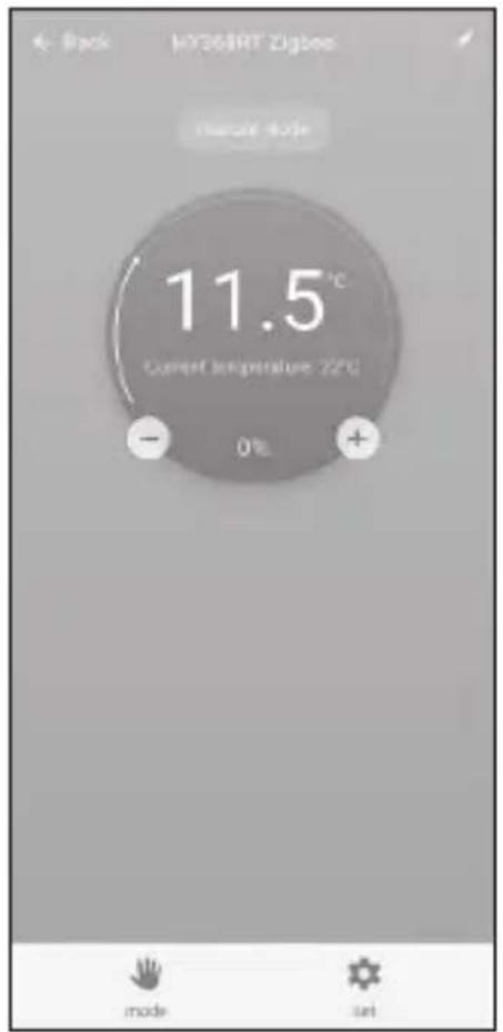
- After opening the head on the „My Home“ page in EMOS GoSmart, you will see the main screen of the thermostatic head (see fig. 7).
- The main screen has 2 buttons: Mode and Settings.
- Tapping the Mode button allows you to select your mode of choice.
- Tapping the Settings button allows you to adjust the settings of individual modes or activate the child lock.
Setting Temperature
The thermostatic head enables setting 4 different temperatures.
Manual temperature

- Temperature that can be adjusted manually either by hand (turning the head) or in the app (using the + button on the main screen of the app).
Holiday temperature

- A constant temperature that can be set for a specific time period (1 day, 2 days, 5 days, 14 days etc.).
Comfort temperature

- A higher temperature (there are people in the room).
ECO temperature

- A lower temperature (temperature for the night or for when there are no people in the room).
Temperature Programmes
The type of temperature programme can be selected on the Calendar Mode page in EMOS GoSmart.
Types of temperature programmes:
- 5+2 (Mon -> Fri + Sat -> Sun)
- allows setting a fixed temperature for the 5 workdays + 2 weekend days
- allows setting up to 6 time periods for both types of days
• 6+1 (Mon -> Sat + Sun)
- allows setting a fixed temperature for 6 days (Monday to Saturday) + Sunday
- allows setting up to 6 time periods for both types of days
- 7 days
- allows settings a fixed temperature for 7 days
- allows setting up to 6 time periods for both types of days
The time periods are set on the „Weekly Programme Settings“ screen in EMOS GoSmart. For each time period, set the temperature that the thermostatic head should set from the time you specify in the time period settings. The temperature you have set will remain active until the next time period.
Example: If you set time periods in line with the table below, room temperature will be 16 °C from 3:00 to 6:00, then 20 °C from 6:00 to 9:00, 17 °C from 9:00 to 12:00, 19 °C from 12:00 to 14:00, 23 °C from 14:00 to 22:00 and 17 °C from 22:00 to 3:00.
| 1st time period 3:00 16 °C | ||
| 2nd time period 6:00 20 °C | ||
| 3rd time period 9:00 17 °C | ||
| 4th time period 12:00 19 °C | ||
| 5th time period 14:00 23 °C | ||
| 6th time period 22:00 17 °C |
Advanced Settings
Temperature Calibration
- The temperature sensor that detects ambient temperature is located in the body of the thermostatic head which is mounted onto the radiator. The measured temperature may therefore be higher than the temperature in other parts of the room.
- Calibration can be set in EMOS GoSmart in a range of -9^ to 9^ with 1^ resolution.
Open Window Function

- If the thermostatic head detects a sudden drop in temperature (e.g. when the window or door is open), it closes the valve.
- Once the set time limit elapses or you close the window, the head automatically reopens the valve.
Automatic Lock Function
- The function can be set in the EMOS GoSmart app.
- If the function is on, the screen automatically locks after 10 minutes without any activity.
- You can unlock the screen again in EMOS GoSmart.
Setting Temperature Setting Limits for Manual Setting of the Thermostatic Head
- Maximum temperature setting limit – specifies the maximum temperature that can be set on the thermostatic head (max. 70 °C, 1 °C resolution)
- Minimum temperature setting limit – specifies the minimum temperature that can be set on the thermostatic head (min. 1 °C, 1 °C resolution)
Adjusting the Valve
- The EMOS GoSmart app can be used to set the position of the valve in your thermostatic head („Closed“, „Open“, „Normal“).
Displaying the Current Temperature in the Room
- The EMOS GoSmart app shows the current temperature in the room right on the main page of the thermostatic head.
Child Lock
- You can activate/deactivate the child lock in the settings of the EMOS GoSmart app.
- If the lock is active, the screen of the thermostatic head or the main page of the head in the EMOS GoSmart app will show a lock icon.
Boost Mode Boost
- The Boost mode can be used to heat up a room within a time you set.
- The time can be set in the EMOS GoSmart app in the Boost tab.
- The length of the heating interval can be set to 100–900 seconds.
Temperature Differential Setting
- This feature can only be adjusted on the screen of the thermostatic head itself.
- The differential can be set to 0.5^ , 1^ , 1.5^ .
- The temperature differential (hysteresis) is the difference in temperature required for switching the heating system on and off.
- For instance, if you set the temperature to 20 °C and the differential to 1 °C, the thermostatic head activates heating as soon as room temperature drops to 19 °C and switches heating off when temperature reaches 21 °C.
Controlling the Valve
- Can only be adjusted on the screen of the thermostatic head itself.
- These controls enable you to set how the valve of the thermostatic head is to be controlled.
- Value = 0: control in accordance with the modes you have set; value = 1 automatic control based on current temperature.
-
When automatic control is selected, the valve is controlled as follows:
-
If the temperature you set is 2 °C higher than the temperature in the room, the valve is 100 % open.
- If the temperature you set is 1 °C higher than the temperature in the room, the valve is 75 % open.
- If the temperature you set is the same (±0.5 °C) as the temperature in the room, the valve is 50 % open.
- If the temperature you set is 1 °C lower than the temperature in the room, the valve is 25 % open.
- If the temperature you set is 2 °C lower than the temperature in the room, the valve is closed.
Setting Modes and Functions on the Screen of the Thermostatic Head
- Once batteries are inserted, the thermostatic head turns on and the entire screen lights up. Then the Week icon will light up. Pressing the Boost oK button allows you to set the current time. Set, in this order, hours, minutes
and day of the week (1 – Monday, 2 – Tuesday, 3 – Wednesday, 4 – Thursday, 5 – Friday, 6 – Saturday, 7 – Sunday). The time and day of the week is set using the rotary wheel on the thermostatic head.
- Once you have set the time, confirm it by pressing the Boost oK button.
- The letters Ad will appear after confirming. Continue by pressing the button.
- The thermostatic head will start calibrating in two steps (the steps are indicated by a number on the screen).
- Once calibration is complete, the screen will show the current temperature in the room and you can begin setting individual functions and modes on the thermostatic head.
1. Setting Weekly Mode
a. To set up weekly mode, hold the 🎨 button for 5 seconds. This opens the thermostatic head's settings.
b. Once you have completed the previous step, the Prog will start flashing. Press the Boost button to confirm your selection of Weekly Mode.
c. Next, use the rotary wheel to select which Weekly Schedule you want to set (5+2, 6+1, 7) .
d. After you have selected the Weekly Schedule, use the rotary wheel to choose the time for the 1st time period of the workday and the temperature for the period. Confirm the selected time and temperature by pressing the Boost oK button.
e. Once you have set the first 6 time periods of the workday, the number 1 will appear on the top of the screen to indicate that you are now setting time periods for a weekend day. Set the time and temperature in the same manner as you did for the workdays.
f. After you have set all time periods, you can either go back to setting the thermostatic head using the 🎨 button or go to the main screen using the 🎩 button. If you confirm any action in the settings by pressing ,ok the data is automatically saved.
g. If you have set up a Weekly Mode, you can activate it by short-pressing the button. The mode is active when the and icons are lit up on the screen.
2. Setting the Current Time
a. If you wish to adjust the time you have set when starting up the thermostatic head, hold the 📄 button for 5 seconds. This opens the thermostatic head's settings.
b. Select the time setting option by repeatedly pressing the button. Time setting is selected once the Week icon starts flashing. Press to confirm the selection of the setting.
c. Once you are in settings, set the time and the day of the week (1 – Monday, 2 – Tuesday, 3 – Wednesday, 4 – Thursday, 5 – Friday, 6 – Saturday, 7 – Sunday).
d. Confirm all steps by pressing the ^Boost button. This will save the settings.
e. After you have set the time of choice, you can either go back to setting the thermostatic head using the 🎨 button or go to the main screen using the 🔊 button.
3. Setting Holiday Mode
a. To set up Holiday Mode, hold the 📋 button for 5 seconds. This opens the thermostatic head's settings.
b. Select the Holiday Mode settings option by repeatedly pressing the button. Holiday Mode settings are selected when the icon starts flashing. Press BOOST to confirm the selection of the setting.
c. Once you are inside Holiday Mode settings, set, in this order, the temperature you want to maintain during the mode and the duration of Holiday Mode. Confirm each step by pressing the BOOST button.
d. Once you have confirmed your chosen Holiday Mode duration, the thermostatic head navigates back to the main screen and Holiday Mode will be active.
4. Setting ECO Mode
a. To set up ECO Mode, hold the 📋 button for 5 seconds. This opens the thermostatic head's settings.
b. Select the ECO Mode settings option by repeatedly pressing the 🎨 button. ECO Mode settings are selected when the 🔊 icon starts flashing. Press to confirm the selection of the setting.
c. Once you are inside ECO Mode settings, use the rotary wheel on the thermostatic head to set the temperature and confirm by pressing the BOOST button.
d. Once you have confirmed your chosen ECO Mode temperature, the thermostatic head navigates back to the main screen.
5. Setting Comfort Mode
a. To set up Comfort Mode, hold the 📄 button for 5 seconds. This opens the thermostatic head's settings.
b. Select the Comfort Mode settings option by repeatedly pressing the button. Comfort Mode settings are selected when the icon starts flashing. Press Boost to confirm the selection of the setting.
c. Once you are inside Comfort Mode settings, use the rotary wheel on the thermostatic head to set the temperature and confirm by pressing the Boost button.
d. Once you have confirmed your chosen Comfort Mode temperature, the thermostatic head navigates back to the main screen.
6. Setting Temperature Calibration
a. To set Temperature Calibration, hold the 📄 button for 5 seconds. This opens the thermostatic head's settings.
b. To select Temperature Calibration, repeatedly press the button. Temperature Calibration settings are selected when the SET icon starts flashing. Press BOOST to confirm the selection of the setting.
c. Confirming the previous step takes you to the advanced settings of the thermostatic head. There, Temperature Calibration is marked by the number 1 in the top right corner of the screen. Temperature calibration can be set to between -9 °C and 9 °C. The value shown on the screen is based on current temperature in the room.
d. Confirm temperature calibration by pressing Boost oK. Confirming redirects you to the next advanced setting (setting the Open Window function, marked by the number 2 in the top right corner of the screen).
e. To go back to settings of the thermostatic head, press 📂. To return to the main screen, press 🔊.
7. Setting the Open Window Function
a. To set the Open Window function, hold the button for 5 seconds. This opens the thermostatic head's settings.
b. To select the Open Window function, repeatedly press their button. Open Window function settings are selected when the SET icon starts flashing. Press Boost to confirm the selection of the setting.
c. Confirming the previous step takes you to the advanced settings of the thermostatic head. To navigate in the advanced settings, press BOOST oK. There, the Open Window function is marked by the number 2 in the top right corner of the screen.
d. Once 2 and the icon appear in the top right corner of the screen, you can set the temperature at which the Open Window function should activate. You can set the temperature to between 5 °C and 25 °C, or you can turn off the function completely. If you wish to turn off the function, turn the wheel on the thermostatic head counter-clockwise until two dashes appear on the screen.
e. To confirm your setting of the Open Window function, press the BOOST button. Confirming redirects you to the next advanced setting (setting the Auto Lock function, marked by the number 3 in the top right corner of the screen).
f. To go back to settings of the thermostatic head, press 📄. To return to the main screen, press 🙏.
8. Automatic Screen Lock Function
a. To set the Auto Lock function, hold the 📋 button for 5 seconds. This opens the thermostatic head's settings.
b. To select the Auto Lock function, repeatedly press the button. The Auto Lock function is selected when the SET icon starts flashing. Press to confirm the selection of the setting.
c. Confirming the previous step takes you to the advanced settings of the thermostatic head. To navigate in the advanced settings, press Boost oK. There, the Auto Lock function is marked by the number 3 in the top right corner of the screen.
d. Once 3 and the icon appear in the top right corner of the screen, you can use the rotary wheel on the thermostatic head to choose whether you wish to turn the function on or off. 0 = function inactive. 1 = function active.
e. To confirm your setting of the Auto Lock function, press the BOOST oK button. Confirming redirects you to the next advanced setting (Minimum Temperature Setting Limit settings, marked by the number 4 in the top right corner of the screen).
f. To go back to settings of the thermostatic head, press 📄. To return to the main screen, press 🔍.
9. Setting the Minimum Temperature Setting Limit
a. To set the Minimum Temperature Setting Limit, hold the 📋 button for 5 seconds. This opens the thermostatic head's settings.
b. To select the Minimum Temperature Setting Limit settings, repeatedly press the 📄. button. The Minimum Temperature Setting Limit option is selected when the SET icon starts flashing. Press Boost OR confirm the selection of the setting.
c. Confirming the previous step takes you to the advanced settings of the thermostatic head. To navigate in the advanced settings, press BOOST oK. There, Minimum Temperature Setting Limit settings are marked by the number 4 in the top right corner of the screen.
d. Once the number 4 appears in the top right of the screen, you can use the rotary wheel on the thermostatic head to set the Minimum Temperature Setting Limit. The temperature can be set to between 1^ and 15^ .
e. To confirm your Minimum Temperature setting, press the BOOST button. Confirming redirects you to the next advanced setting (Maximum Temperature Setting Limit settings, marked by the number 5 in the top right corner of the screen).
f. To go back to settings of the thermostatic head, press 📄. To return to the main screen, press 🔍.
10. Setting the Maximum Temperature Setting Limit
a. To set the Maximum Temperature Setting Limit, hold the button for 5 seconds. This opens the thermostatic head's settings.
b. To select the Maximum Temperature Setting Limit settings, repeatedly press the 📄 button. The Maximum Temperature Setting Limit option is selected when the SET icon starts flashing. Press 🐨 to confirm the selection of the setting.
c. Confirming the previous step takes you to the advanced settings of the thermostatic head. To navigate in the advanced settings, press Boost oK. There, Maximum Temperature Setting Limit settings are marked by the number 5 in the top right corner of the screen.
d. Once the number 5 appears in the top right of the screen, you can use the rotary wheel on the thermostatic head to set the Maximum Temperature Setting Limit. The temperature can be set to between 16^ and 70^ .
e. To confirm your Maximum Temperature setting, press the BOOST button. Confirming redirects you to the next advanced setting (setting of the interval length of the Boost function, marked by the number 6 in the top right corner of the screen).
f. To go back to settings of the thermostatic head, press 🎨. To return to the main screen, press 🔊.
11. Setting the Interval Length of the Boost Function
a. To set the interval length of the Boost function, hold the button for 5 seconds. This opens the thermostatic head's settings.
b. To select the Boost function settings, repeatedly press the button. The Boost option is selected when the SET icon starts flashing. Press to confirm the selection of the setting.
c. Confirming the previous step takes you to the advanced settings of the thermostatic head. To navigate in the advanced settings, press Boost OK. There,
Boost interval length settings are marked by the number 6 in the top right corner of the screen.
d. Once the number 6 appears in the top right of the screen, you can use the rotary wheel on the thermostatic head to set the length of the interval of the Boost function. The value can be set to between 100 and 900 seconds.
e. Confirm your chosen Boost interval length by pressing BOOST oK. Confirming redirects you to the next advanced setting (setting of the start/end of working temperature, marked by the number 7 in the top right corner of the screen).
f. To go back to settings of the thermostatic head, press 📄. To return to the main screen, press 📋.
12. Setting the Start/End Working Temperature
a. To set the start/end working temperature, hold the button for 5 seconds. This opens the thermostatic head's settings.
b. To select the start/end working temperature settings, repeatedly press the button. The start/end working temperature option is selected when the SET icon starts flashing. Press Boost OR confirm the selection of the setting.
c. Confirming the previous step takes you to the advanced settings of the thermostatic head. To navigate in the advanced settings, press Boost oK. There, start/end working temperature settings are marked by the number 7 in the top right corner of the screen.
d. Once the number 7 appears in the top right of the screen, you can use the rotary wheel on the thermostatic head to set the start/end working temperature. The value can be set to between 0.5 °C and 1.5 °C.
e. To confirm the start/end working temperature setting, press the BOOST button. Confirming redirects you to the next advanced setting (Type of Valve Control, marked by the number 8 in the top right corner of the screen).
f. To go back to settings of the thermostatic head, press 📂. To return to the main screen, press 🔊.
13. Valve Control
a. To set Valve Control, hold the 📄 button for 5 seconds. This opens the thermostatic head's settings.
b. To select the Valve Control settings option, repeatedly press the button. The Valve Control function is selected when the SET icon starts flashing. Press BOOST to confirm the selection of the setting.
c. Confirming the previous step takes you to the advanced settings of the thermostatic head. To navigate in the advanced settings, press Boost oK. There, Valve Control settings are marked by the number 8 in the top right corner of the screen.
d. Once the number 8 appears in the top right of the screen, you can use the rotary wheel on the thermostatic head to set the type of valve control. Value = 0: control in accordance with the modes you have set; value = 1 automatic control based on current temperature.
e. To confirm your Valve Control settings, press the Boost oK button. Confirming redirects you to the next advanced setting (Reset Thermostatic Head, marked by the number 9 in the top right corner of the screen).
f. To go back to settings of the thermostatic head, press 🎨. To return to the main screen, press 🔊.
14. Reset the Thermostatic Head
a. To Reset the Thermostatic Head, hold the 🎨 button for 5 seconds. This opens the thermostatic head's settings.
b. To select the Reset the Thermostatic Head settings option, repeatedly press the button. The Reset the Thermostatic Head option is selected when the SET icon starts flashing. Press to confirm the selection of the setting.
c. Confirming the previous step takes you to the advanced settings of the thermostatic head. To navigate in the advanced settings, press BOOST oK. There, the Reset the Thermostatic Head option is marked by the number 9 in the top right corner of the screen.
d. Once the number 9 appears in the top right of the screen, the screen also shows the number 88. Turning the rotary wheel of the thermostatic head changes the number to 00. Confirming with the Boost oK button resets the head. All icons on the screen will light up for 2 seconds.
e. To go back to settings of the thermostatic head, press 📄 to return to the main screen, press 🙏️.
Upkeep and Maintenance
The product is designed to serve reliably for many years if used properly. Here are some tips for proper operation:
- Read the manual carefully before using this product.
- Do not expose the product to direct sunlight, extreme cold, humidity and sudden changes in temperature. This would reduce measuring accuracy.
- Do not place the product in locations prone to vibration and shocks – may cause damage.
- Do not subject the product to excessive force, impacts, dust, high temperatures or humidity – doing so may cause malfunction, shorten battery life, damage the batteries or deform the plastic parts.
- Do not expose the product to rain or high humidity, dropping or splashing water.
- Do not place any open flame sources on the product, e.g. a lit candle, etc.
- Do not put the product in places with inadequate air flow.
- Do not insert any objects in the product's vents.
- Do not tamper with the internal electric circuits of the product – doing so may damage the product and will automatically void the warranty. The product should only be repaired by a qualified professional.
- To clean the product, use a slightly moistened soft cloth. Do not use solvents or cleaning agents – they could scratch the plastic parts and cause corrosion of the electric circuits.
- Do not immerse the product in water or other liquids.
- In the event of damage or defect of the product, do not make any repairs by yourself. Have it repaired in the shop where you bought it.
- This device is not intended for use by persons (including children) whose physical, sensory or mental disability or lack of experience and expertise prevents safe use, unless they are supervised or instructed in the use of the appliance by a person responsible for their safety. Children must always be supervised to ensure they do not play with the device.

Do not dispose with domestic waste. Use special collection points for sorted waste. Contact local authorities for information about collection points. If the electronic devices would be disposed on landfill, dangerous substances may reach groundwater and subsequently food chain, where it could affect human health.
- 6+1 (Pon -> Sob + Ned)
- 5+2 (Pon. -> Pet. + Sub. -> Ned.)
- omogućuje postavljanje fiksne temperature za 5 radnih dana + 2 dana vikenda
- omogućuje postavljanje do 6 vremenskih razdoblja za obje vrste dana
- 6+1 (Pon. -> Sub. + Ned.)
Configuration/adaptation de base
Voeding: 2× 1,5 V AA
Maximale stroomafname: 90 mA