P56201UF - Thermostat Emos - Free user manual and instructions
Find the device manual for free P56201UF Emos in PDF.

User questions about P56201UF Emos
0 question about this device. Answer the ones you know or ask your own.
Ask a new question about this device
Download the instructions for your Thermostat in PDF format for free! Find your manual P56201UF - Emos and take your electronic device back in hand. On this page are published all the documents necessary for the use of your device. P56201UF by Emos.
USER MANUAL P56201UF Emos
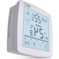
GB | Floor Heating Thermostat

Contents
Important....2
Technical specifications .... 3
Description of the Thermostat Screen – Icons and Buttons ....4
Installing the Thermostat....6
Mobile Application 8
Advanced Settings....10
Troubleshooting FAQ....15
Upkeep and Maintenance 16
The P56201UF/P56201BUF thermostat is designed for controlling underfloor heating.
Important
- Read the thermostat manual carefully before using the device for the first time.
- Turn off power before installing the thermostat!
- Follow prescribed standards during installation.

Technical specifications
Switched load: max. 230 V AC; 16 A for resistive load
Temperature measurement: 0 °C to 95 °C, 0.5 °C resolution
Temperature setting: 1 °C to 70 °C, in 0.5 °C increments
Temperature differential setting: 0.5 °C to 2.5 °C, in 0.5 °C increments
Calibration of set temperature: -9 °C to 9 °C, in 1 °C increments
Power supply: 230 V
Enclosure rating: IP20
Accessories: 3 m floor sensor ( 8 mm), installation equipment
WiFi frequency: 2.4 GHz, max. 25 mW e.i.r.p.
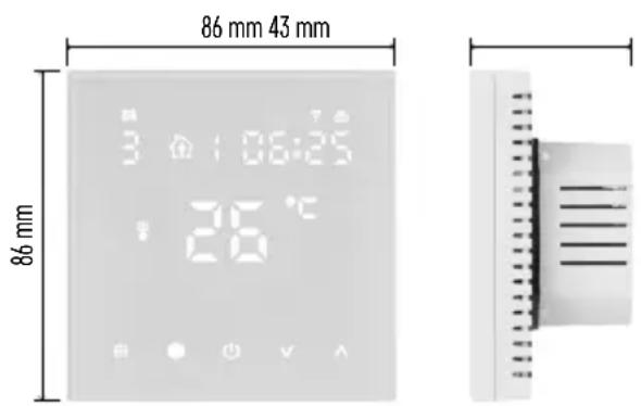
Dimensions: 86 × 86 × 43 mm

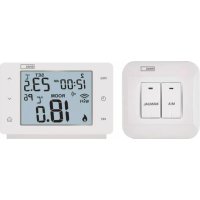
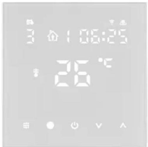
Description of the Thermostat Screen – Icons and Buttons
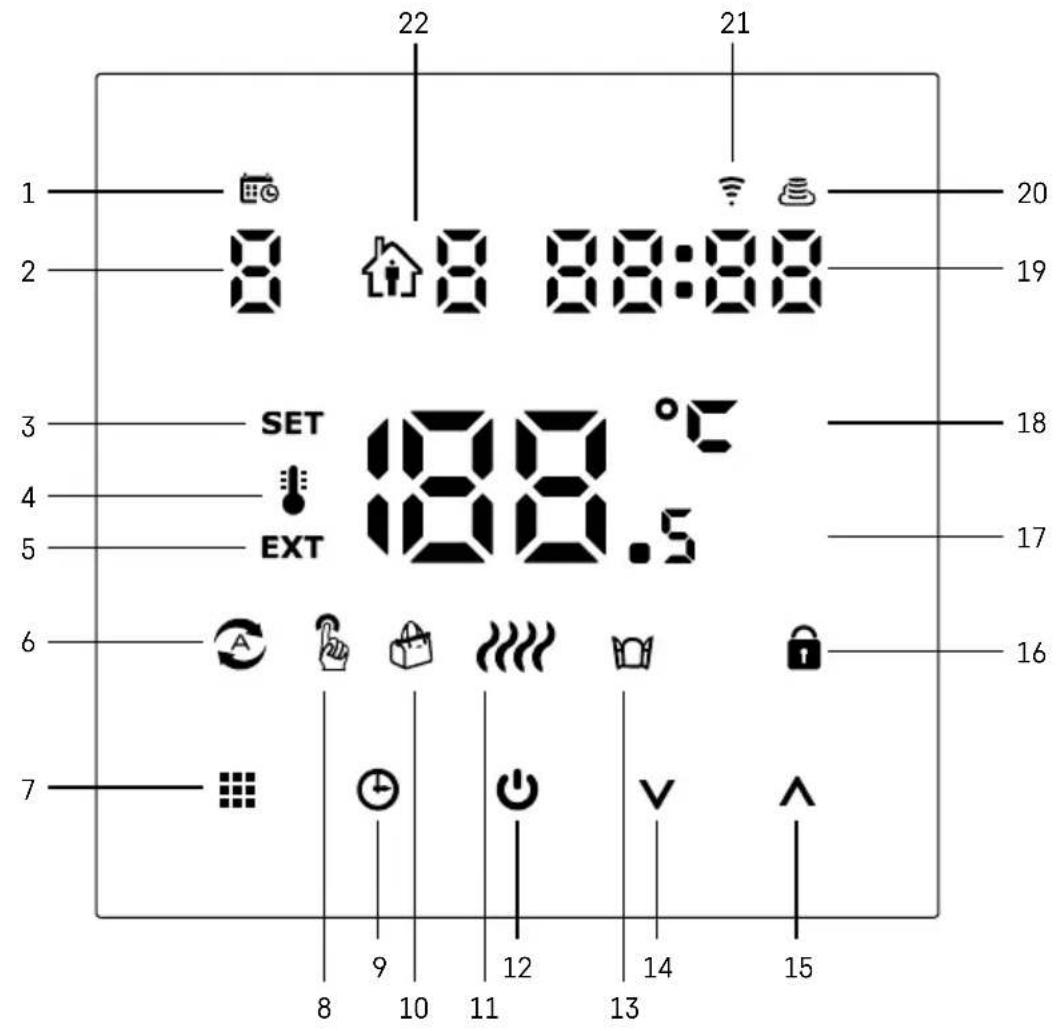
1 – The 📋 indicates the day of the week.
2 – Number of the day of the week (1 – Monday, 2 – Tuesday, 3 – Wednesday, 4 – Thursday, 5 – Friday, 6 – Saturday, 7 – Sunday).
3 – TheSET icon appearing on the screen indicates that the screen is showing the temperature you have set for the given mode.
4 – If the icon is on the screen, the screen is showing the current temperature in the room (if the thermostat's internal sensor is active).
5 – If the EXT icon is on the screen, the screen is showing the temperature from the floor sensor. In a mode where both sensors are measuring temperature, you can display the this temperature by holding the Afor 3 seconds.
6 - 4con on the screen indicates that Weekly Mode is active.
7 – The button switches between Weekly and Manual Mode.
8 - Icon on the screen indicates that Manual Mode is active.
9 - The ⏻ button sets time.
10 - icon on the screen indicates that Holiday Mode is active.
11 - Icon appearing on the screen indicates that the thermostat is currently heating up the room.
12 - ⬤ is the ON/OFF button.
13 - 10 on the screen indicates the open window function is active.
14 – The button is used to move down.
15 - The Button is used to move up.
16 - icon on the screen indicates that child lock is active.
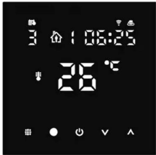
17 - Current room temperature.
18 - °C unit of temperature.
19 - Current time.
20 - The icon indicates connection to the Cloud (AP).
21 - The icon indicates connection through Wi-Fi (EZ).
22 – The 🔊 icon indicates which time period of Weekly Mode is currently active.
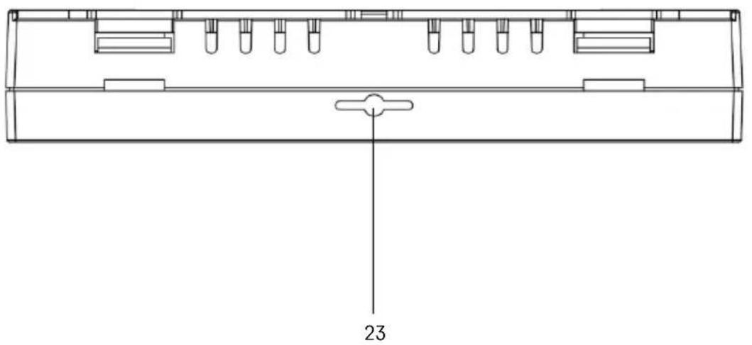
23 - Location of the indoor temperature sensor

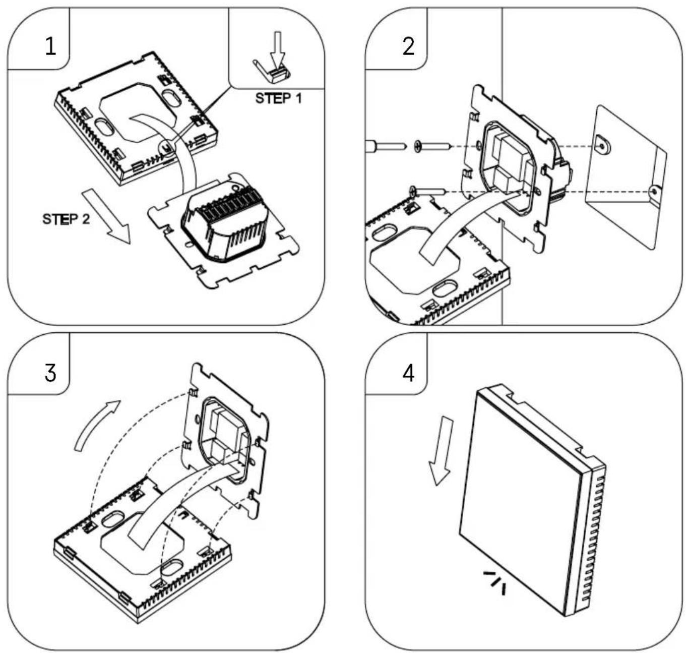
Installing the Thermostat
Attention:
Before changing the thermostat, disconnect the heating system from the mains power in your flat. This will prevent potential injury by electric current.
Placement of the Thermostat
The placement of the thermostat significantly affects its functioning. Choose a location where members of the family spend most of their time, preferably on the inside wall where air circulates freely, with no direct sunlight. Do not place the thermostat in the vicinity of heat sources (such as TV sets, radiators, fridges), or close to a door (due to frequent shocks or vibrations). If you do not follow these recommendations, the thermostat will not maintain room temperature correctly.
- Use a screwdriver to press on the internal lock and slide out the metal frame. If necessary, carefully disconnect the internal connector joining the two parts of the thermostat together.
- Install the mounting plate onto a suitable junction box, e.g. KU 68.
- Connect the wires leading out of the junction box to the marked terminals on the thermostat in accordance with the wiring diagram. Reconnect the internal connector, fit the thermostat back onto the mounting plate and secure it with the metal frame.
- Replace the front cover.
Wiring Diagram
AC90-240V 50/60Hz
Imax:16A

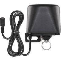
LOAD - connected device
N, L - thermostat's power supply
NTC - floor sensor

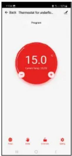
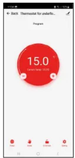
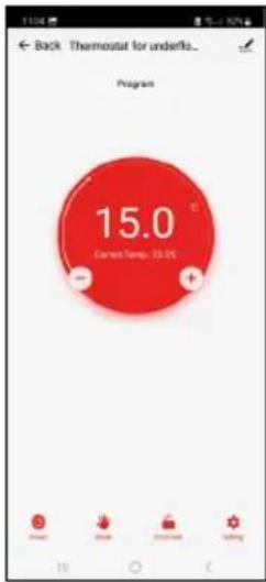
Mobile Application
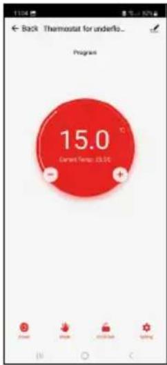
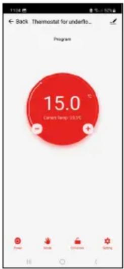
The thermostat can be controlled using a mobile application for iOS or Android. Download the EMOS GoSmart app for your device.


Tap the Log In button if you've used the app before. Otherwise, tap the Sign Up button and register.
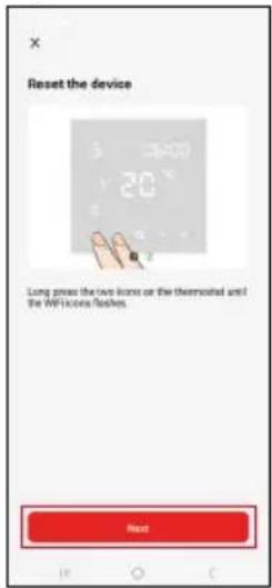
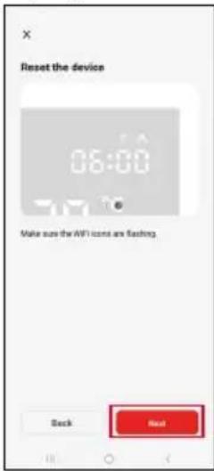
Pairing with the Mobile Application
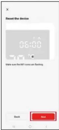
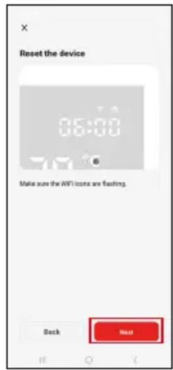
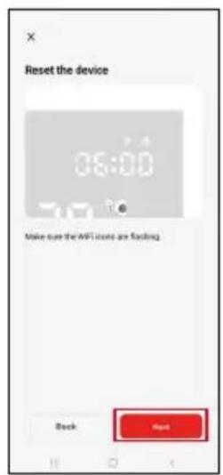
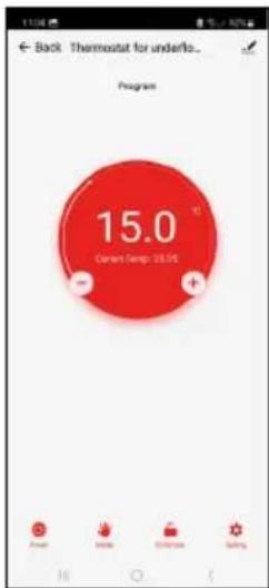
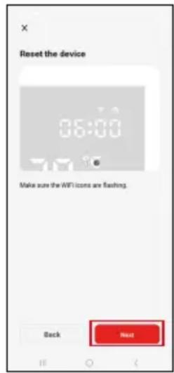
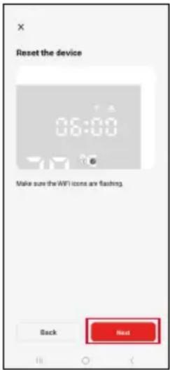
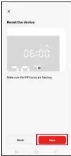
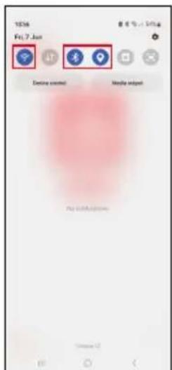
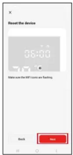
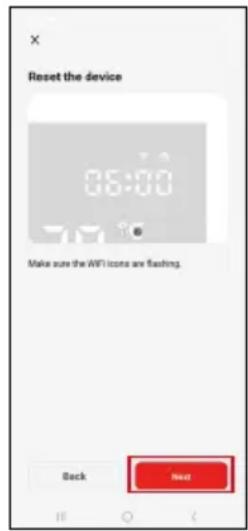
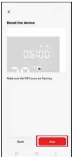
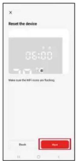
Long-press both the 🎨 and ⏻ button on the thermostat simultaneously. The 🎨 and 🔊 icons on the thermostat screen will start flashing; the thermostat is now in pairing mode.
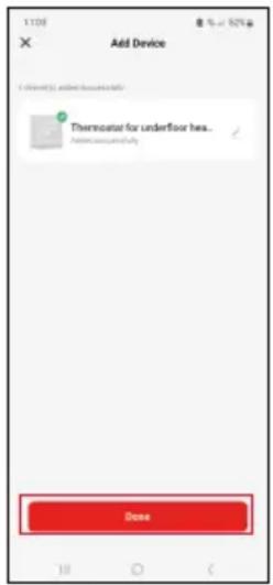
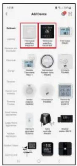
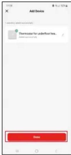
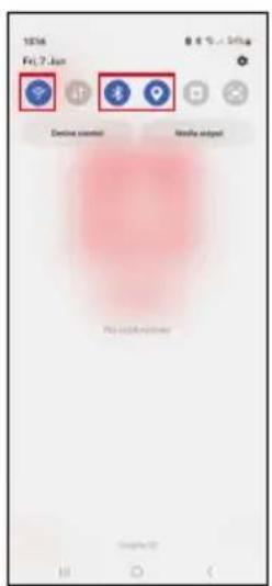
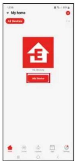
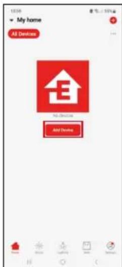
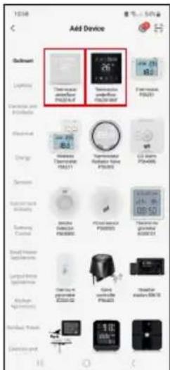
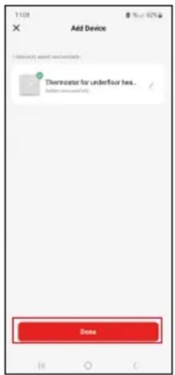
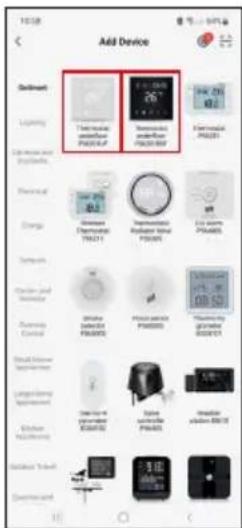
Tap Add Device in the app.
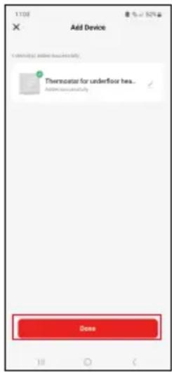
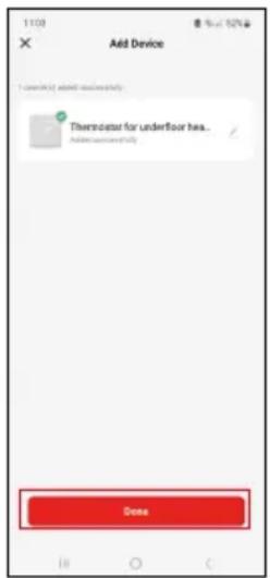
Tap the GoSmart list on the left and tap the Thermostat underfloor P56201UF/P56201BUF icon.
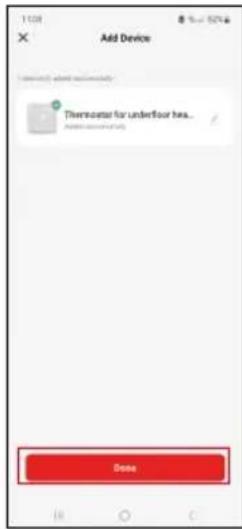

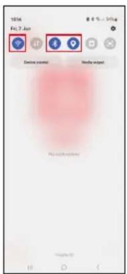
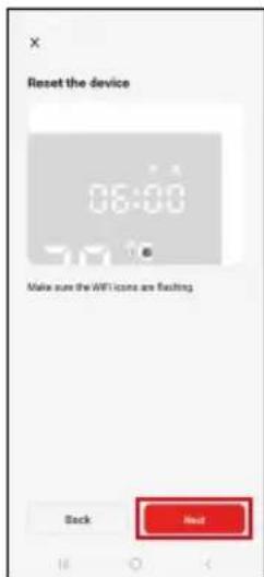
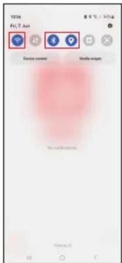
Follow the instructions in the app and enter the name and password for your 2.4 GHz Wi-Fi network.
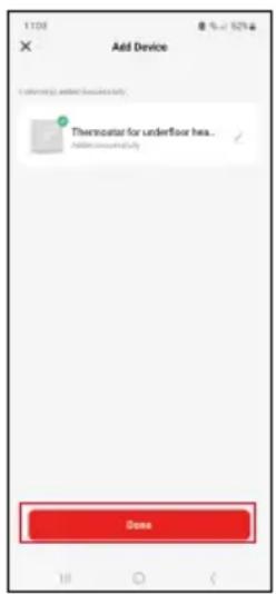
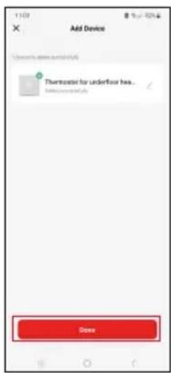
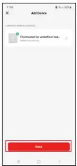
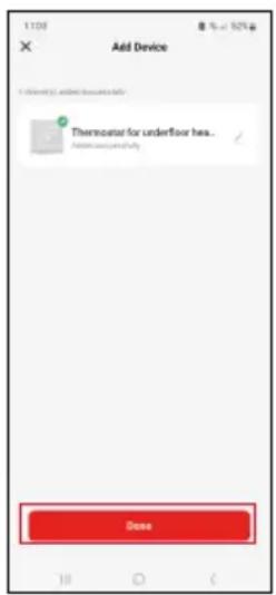
The gateway will pair with the app within 2 minutes.
Note: If the thermostat fails to pair, repeat the entire process from the start. 5 GHz Wi-Fi networks are not supported.
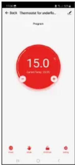
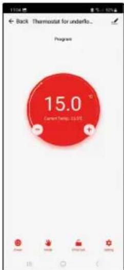
Temperature Programmes
The type of temperature programme can be chosen in the Calendar Mode tab in EMOS GoSmart settings.
Types of temperature programmes:
- 5 + 2 (Mo-Fr + Sa + Su)
- Allows setting a fixed temperature for 5 workdays + 2 weekend days.
- Allows setting up to 6 time periods for each type of day.
- 6 + 1 (Mo-Sa + Su)
- Allows setting a fixed temperature for 6 days (Monday to Saturday) + Sunday.
- Allows setting up to 6 time periods for each type of day.
• 7 days
- Allows setting a fixed temperature for 7 days.
- Allows setting up to 6 time periods for each type of day.
Time periods can be set in the Weekly Mode Settings tab in the EMOS GoSmart app. For each time period, set the temperature that should be set on the thermostat from the time you specify in time period settings. The temperature you have set will be active until the next time period.
Example: If you set the time periods in accordance with the table below, the temperature in the room will be set to 16 °C from 3:00 to 6:00, then 20 °C from 6:00 to 9:00, 17 °C from 9:00 to 12:00, 19 °C from 12:00 to 14:00, 23 °C from 14:00 to 22:00 and 17 °C from 22:00 to 3:00.
| 1st time period 3:00 16 °C | |
| 2nd time period 6:00 20 °C | |
| 3rd time period 9:00 17 °C | |
| 4th time period 12:00 19 °C | |
| 5th time period 14:00 23 °C | |
| 6th time period 22:00 17 °C |
Advanced Settings
Temperature Calibration
- The temperature sensor in the thermostat is calibrated from production, but additional calibration can be done to optimise the thermostat further, for instance by comparing the measured room temperature with a reference thermometer.
• Example: The thermostat shows room temperature of 22 °C ; setting calibration to +1 °C will cause the thermostat to display 23 °C instead. - Calibration can be set in EMOS GoSmart in a range of -9^ to 9^ with 1^ resolution.
Temperature Differential
- The temperature differential (hysteresis) is the difference in temperature required for switching the system on and off.
- Example: If you set the temperature in the heating system to 20 °C and differential to 2 °C, the thermostat activates heating as soon as room temperature drops to 18 °C and switches heating off when temperature reaches 22 °C.
- The temperature differential of the internal sensor can be set to between 0.5^ and 2.5^ .
• The temperature differential of the floor sensor can be set to between 1 °C and 9 °C (EMOS GoSmart app).
Temperature Limits for Manual Thermostat Settings
- Maximum temperature setting limit – specifies the maximum temperature that can be set on the thermostat (20 °C to 70 °C, 1 °C resolution).
- Minimum temperature setting limit – specifies the minimum temperature that can be set on the thermostat (1 °C to 20 °C, 1 °C resolution).
Temperature Protection
- High-temperature protection – specifies the maximum temperature the thermostat heats the system up to.
• Example: When temperature protection for the sensor is set to 45 °C and the limit to 2 °C , the thermostat relay switches off if temperature exceeds 45 °C and turns on again if temperature drops to 43 °C . - Note: if you set both the indoor and floor sensor in the "Active temperature sensor" function, the icon will flash permanently.
- Low-temperature protection – specifies the lowest possible room temperature. If the temperature drops below the set value, the thermostat will start automatically heating up the room. Can be set to between 1 °C and 10 °C.
Status of the Device after Reconnecting to Power after a Power Outage
- The same as before turning off – the thermostat returns to the state it was in before the power outage.
- Off – the thermostat stays off after reconnecting.
- On – the thermostat turns on after reconnecting.
Active Temperature Sensor
- The setting defines which sensor is detecting temperature – either the internal sensor, floor sensor or both.
Child Lock
- The child lock is activated/deactivated in the settings of the EMOS GoSmart app or by holding the V button for 3 seconds.
- If the lock is active, a lock icon will be displayed on the thermostat's screen or the thermostat's main page in EMOS GoSmart.
Thermostat Screen Brightness in Standby Mode
- Specifies screen brightness after 10 seconds of inactivity.
- Can only be adjusted in the settings on the thermostat's screen.
- 0 = screen off
- 1 = room temperature is slightly illuminated on the screen
- 2 = room temperature is strongly illuminated on the screen
Open Window Function
- If the thermostat detects a sudden drop in temperature (e.g. when the window or door is open), it stops heating the room.
- The thermostat will resume heating the room after the set time period elapses or after you close the window.
- The function can only be set/turned off in the settings on the thermostat's screen.
Temporary Manual Mode
- Temporary manual mode activates if Weekly Mode is set on the thermostat and you press the √ or √arrow.
- When it is active, the screen will show both the Weekly Mode and Manual Mode icon.
- This mode is turned off only by changing to a different mode.
Holiday Mode
- The Holiday Mode allows you to set a temperature of choice for an extended period of time.
Reset
- The device can be reset to factory settings.
- This function can only be activated through the thermostat's screen (as described below).
Setting Modes and Functions on an Active Thermostat Screen
- Setting Current Time and Day of the Week
a. Press the ⏻ button to set, in order, minutes, hours and day of the week.
b. Change the values using the ∧ and ↗rows.
c. Confirm by pressing 📁 again.
- Setting Weekly Mode
a. Press and hold the button for 3 seconds. This will open workday settings. Set, in order, the hour, minutes and temperature for the first time period of the workday. Confirm each value by pressing the button again. Once you have set the 1st time period, the settings automatically navigate to the 2nd time period. Gradually proceed to up to the 6th time period. After setting the 6th workday time period, you will be redirected to weekend day settings.
b. To set the schedule for the weekend day, repeat the same actions you did to set the schedule for the workday.
c. Change the values using the ∧ and ↗rows.
d. Once you have set the final time period for the weekend day, press the button again and the Weekly Mode is set.
- Setting Holiday Mode
a. Press and hold the ⏻ button for 3 seconds. Once the text OFF or ON starts flashing in the top right corner instead of the clock, you have entered Holiday Mode settings.
b. If you wish to activate Holiday Mode, use the ▲ or △ arrow to switch the flashing text in the top right corner to ON and confirm with ⊕
c. After confirmation, a number will start flashing in the top of the screen indicating the interval of the Holiday Mode. Adjust the interval using the and rows. Confirm by pressing .
d. After confirming the interval, you will be redirected to setting the temperature for Holiday Mode. Adjust the temperature using the and arrows. Confirm by pressing . Confirming activates Holiday Mode.
e. To turn off Holiday Mode, hold the ⏻ button for 3 seconds and change the text to OFF. Confirm with ⏻ to deactivate Holiday Mode.
Setting A Modes and Functions on an Inactive Thermostat Screen
Turn off the thermostat screen using the button. When the screen is off, only the bottom bar of buttons is active. To access the thermostat's advanced settings (A), press and hold the button for 3 seconds.
Adjust values/parameters in any mode or function using the ∧ and ↗rows.
To navigate in advanced settings, press to access the settings for the next function/mode. The functions/modes are marked as A1-AE (in the top right corner of the screen).
Confirm any values you set by pressing
Functions/Modes:
• A1 – Temperature calibration
- Can be set to between -9^ and 9^ .
- The temperature shown on the screen will be adjusted by the Calibration value you have set.
- The Calibration value is displayed in the top of the screen.
• The default setting is -1 °C.
• A2 – Temperature differential
- Can be set to between 0.5^ and 2.5^ .
• The default setting is 1 °C.
• A3 – Screen child lock
- Can be set to 0 or 1.
- 0 = lock off.
- 1 = lock on.
• The default value is 0.
- A4 – Status of the device after reconnecting to power after a power outage
- Can be set to 0, 1 or 2.
- 0 = same status as before the outage.
- 1 = thermostat off.
- 2 = thermostat on.
- The default value is 0.
- A5 – Thermostat screen brightness in standby mode
- Can be set to 0, 1 or 2.
- 0 = screen off.
- 1 = room temperature is slightly illuminated on the screen.
- 2 = room temperature is strongly illuminated on the screen.
- The default value is 2.
• A6 – Calendar Mode selection for Weekly Mode
- Can be set to 0, 1 or 2.
- 0 = 5 + 2 (Mo-Fr + Sa + Su).
- 1 = 6 + 1 (Mo-Sa + Su).
- 2 = 7 days.
- The default setting is 0.
• A7 – Minimum temperature setting
- Can be set to between 1^ and 10^ .
• The default setting is 5 °C.
• A8 – Maximum temperature setting
- Can be set to between 20^ and 70^ .
• The default setting is 35 °C.
• A9 – Low-temperature protection
- Can be set to between 1^ and 10^ or turned off completely.
- The protection is turned off by setting the value to 10^ and pressing the arrow. Two dashes will appear on the screen.
• The default setting is 5 °C.
- AA – High-temperature protection of the external sensor
- Can be set to between 20^ and 70^ or turned off completely.
- The protection is turned off by setting the value to 20^ and pressing the V arrow. Two dashes will appear on the screen.
• The default setting is 45 °C.
- AB – Setting the limit of the sensor's high-temperature protection
- Can be set to between 1^ and 9^ .
• The default setting is 2 °C.
- AC – Open Window function (temperature)
- Can be set to between 10^ and 20^ or turned off completely.
- The function is turned off by setting the value to 10^ and pressing the V arrow. Two dashes will appear on the screen.
- The default setting is off.
- AD – Open window function (interval)
- Can be set to between 10 and 20 minutes.
- The default value is 10 minutes.
- AE - Reset
- Ao is shown on the screen. To reset to factory settings, hold the button for 5 seconds.
Setting B Modes and Functions on an Inactive Thermostat Screen
Turn off the thermostat screen using the button. When the screen is off, only the bottom bar of buttons is active.
To access the thermostat's advanced settings (B), press and hold the ⏻ button for 3 seconds.
Adjust values/parameters in any mode or function using the and varrows.
To navigate in advanced settings, press to access the settings for the next function/mode. The functions/modes are marked as BN, Bo (in the top right corner of the screen).
Confirm any values you set by pressing
Functions/Modes:
- BN – Active temperature sensor
- Can be set to N1, N2 and N3.
- N1 = internal sensor is active.
- N2 = floor sensor is active.
- N3 = internal and floor sensor is active.
• The default value is N1.
- Bo – Product information
- An option that cannot be adjusted.

Troubleshooting FAQ
The screen displays:
E1 - fault of the indoor temperature sensor.
- Reset the thermostat.
- Return the thermostat.
E2 - fault of the floor sensor.
- Reset the thermostat.
- Check that the sensor is connected properly. Check the settings of the active sensor in the thermostat's menu.

Upkeep and Maintenance
The product is designed to serve reliably for many years if used properly. Here are some tips for proper operation:
- Read the manual carefully before using this product.
- Do not expose the product to direct sunlight, extreme cold, humidity and sudden changes in temperature. This would reduce measuring accuracy.
- Do not place the product in locations prone to vibrations and shocks – these may cause damage.
- Do not subject the product to excessive force, impacts, dust, high temperatures or humidity – doing so may cause malfunction, shorten battery life, damage the batteries or deform the plastic parts.
- Do not expose the product to rain or high humidity, dropping or splashing water.
- Do not place any open flame sources on the product, e.g. a lit candle, etc.
- Do not place the product in places with inadequate air flow.
- Do not insert any objects in the product's vents.
- Do not tamper with the internal electric circuits of the product – doing so may damage the product and will automatically void the warranty. The product should only be repaired by a qualified professional.
- To clean the product, use a slightly moistened soft cloth. Do not use solvents or cleaning agents – they could scratch the plastic parts and cause corrosion of the electric circuits.
- Do not immerse the product in water or other liquids.
- In the event of damage or defect of the product, do not make any repairs by yourself. Have it repaired in the shop where you bought it.
- This device is not intended for use by persons (including children) whose physical, sensory or mental disability or lack of experience and expertise prevents safe use, unless they are supervised or instructed in the use of the appliance by a person responsible for their safety. Children must always be supervised to ensure they do not play with the device.

Do not dispose with domestic waste. Use special collection points for sorted waste. Contact local authorities for information about collection points. If the electronic devices would be disposed on landfill, dangerous substances may reach groundwater and subsequently food chain, where it could affect human health.

P56201UF | P56201BUF
natural_image
Technical line drawing of an electronic device with exploded view showing internal components and assembly (no text or symbols)
natural_image
Technical line drawing of a mechanical assembly with no visible text or symbols
natural_image
Diagram of a rectangular electronic device with a side panel and labeled dimension '7-1' (no text or symbols beyond labels)Upozornění:


natural_image
Technical line drawing of an electronic device with exploded view showing internal components and assembly (no text or symbols)
natural_image
Technical line drawing of a mechanical assembly with no visible text or symbols
natural_image
Diagram of a rectangular electronic device with a side panel and arrow indicating rotation (no text or symbols)Upozornenie:


natural_image
Exploded view diagram of a device showing internal components and assembly (no text or labels)
natural_image
Technical line drawing of a mechanical assembly with no visible text or symbols
natural_image
Isometric line drawing of a rectangular device with a side panel and arrow indicating rotation (no text or symbols)Uwagi:


natural_image
Technical line drawing of an electronic device with exploded view showing internal components and assembly (no text or symbols)
natural_image
Technical line drawing of a mechanical assembly with no visible text or symbols
natural_image
Diagram of a rectangular electronic device with a side panel and arrow indicating rotation (no text or symbols)Opozorilo:


Sledite navodilom v aplikaciji in vnesite ime in geslo omrežja Wi-Fi 2,4 GHz.
V 2 minutah je aplikacija povezana.
Opomba: Če termostata ne uspe povezati, celoten postopek ponovite. Omrežje Wi-Fi 5 GHz ni podprto.
Temperaturni programi
- 5 + 2 (Pon-Pet + Sob + Ned)
• 6 + 1 (Pon-Sob + Ned)
LOAD - povezani uređaj
N, L - napajanje termostata
NTC - podni senzor

Mobilna aplikacija
Termostatom se može upravljati pomoću mobilne aplikacije za iOS ili Android. Preuzmite aplikaciju EMOS GoSmart za svoj uređaj.


Dodirnite gumb Prijava ako ste već koristili aplikaciju. U protivnom dodirnite gumb Prijavi se i registrirajte se.
- 5 + 2 (pon-pet + sub + ned)
- Omogućuje postavljanje fiksne temperature za 5 radnih dana + 2 dana vikenda.
- Omogućuje postavljanje do 6 vremenskih razdoblja za svaku vrstu dana.
- 6 + 1 (pon-sub + ned)
natural_image
Technical line drawing of an electronic device with exploded view showing internal components and assembly (no text or symbols)
natural_image
Technical line drawing of a mechanical assembly with no visible text or symbols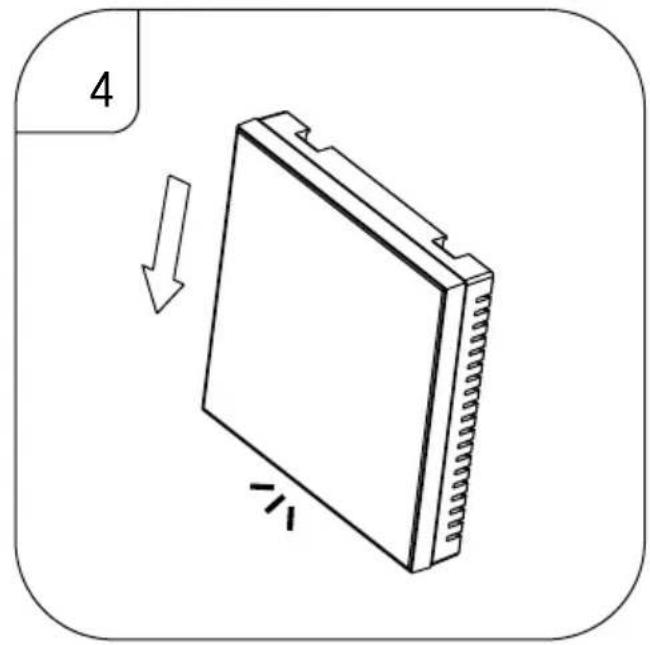
natural_image
Diagram of a rectangular electronic device with a side panel and arrow indicating rotation (no text or symbols)Achtung:


natural_image
Technical line drawing of an electronic device with exploded view showing internal components and assembly (no text or symbols)
natural_image
Technical line drawing of a mechanical assembly with no visible text or symbols
natural_image
Diagram of a rectangular electronic device with a side panel and labeled dimension '7-1' (no text or symbols beyond labels)Попередження:


natural_image
Technical line drawing of an electronic device with exploded view showing internal components and assembly (no text or symbols)
natural_image
Technical line drawing of a mechanical assembly with no visible text or symbols
natural_image
Diagram of a rectangular electronic device with a side panel and arrow indicating rotation (no text or symbols)Atentionare:
LOAD – dispozitivul conectat


natural_image
Technical line drawing of a mechanical component with multiple ports and a central pin (no text or symbols)LOAD (APKROVA) – prijungtas prietaisas
N, L - termostato maitinimas
NTC – grindinis jutiklis

Mobilioji programèlè


natural_image
Exploded view diagram of a device showing internal components and assembly (no text or labels)
natural_image
Technical line drawing of a mechanical assembly with no visible text or symbols
natural_image
Diagram of a rectangular device with a folded top and side connectors, showing an arrow indicating rotation or movement (no text or symbols)Внимание:


Application mobile....8
Réglages avancés du thermostat....10
natural_image
Exploded view diagram of a device showing internal components and assembly (no text or labels)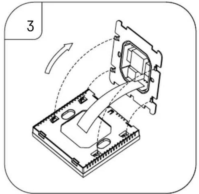
natural_image
Isometric line drawing of a device with internal components and directional arrows indicating motion (no text or symbols)
natural_image
Diagram of a rectangular device with a folded top and side connectors, showing an arrow indicating rotation or movement (no text or symbols)Avertissement :


natural_image
Technical line drawing of an electronic device with exploded view showing internal components and assembly (no text or symbols)
natural_image
Technical line drawing of a mechanical assembly with no visible text or symbols
natural_image
Diagram of a rectangular electronic device with a side panel and arrow indicating rotation (no text or symbols)Avvertenza:


natural_image
Technical line drawing of an electronic device with exploded view showing internal components and assembly (no text or symbols)
natural_image
Technical line drawing of a mechanical assembly with no visible text or symbols
natural_image
Diagram of a rectangular electronic device with a side panel and arrow indicating rotation (no text or symbols)Waarschuwing:


natural_image
Technical line drawing of an electronic device with exploded view showing internal components and assembly (no text or symbols)
natural_image
Technical line drawing of a mechanical assembly with no visible text or symbols
natural_image
Diagram of a rectangular electronic device with a side panel and arrow indicating rotation (no text or symbols)Advertencia:


natural_image
Technical line drawing of an electronic device with exploded view showing internal components and assembly (no text or symbols)
natural_image
Technical line drawing of a mechanical assembly with no visible text or symbols
natural_image
Diagram of a rectangular electronic device with a side panel and arrow indicating rotation (no text or symbols)Atenção:
LOAD - dispositivo ligado


natural_image
Technical line drawing of an electronic device with exploded view showing internal components and assembly (no text or symbols)
natural_image
Technical line drawing of a mechanical assembly with no visible text or symbols
natural_image
Diagram of a rectangular electronic device with a side panel and arrow indicating rotation (no text or symbols)Huomio:


natural_image
Technical line drawing of an electronic device with exploded view showing internal components and assembly (no text or symbols)
natural_image
Technical line drawing of a mechanical assembly with no visible text or symbols
natural_image
Diagram of a rectangular electronic device with a side panel and arrow indicating rotation (no text or symbols)Bemaerk!