
ACTracer - Measuring equipment Laserliner - Free user manual and instructions
Find the device manual for free ACTracer Laserliner in PDF.
| Product type | Line detector kit with transmitter and receiver |
| Brand | Laserliner |
| Model | ACTracer |
| Dimensions (transmitter) | 50 x 80 x 32 mm |
| Weight (transmitter) | approx. 54 g |
| Dimensions (receiver) | 68 x 165 x 36 mm |
| Weight (receiver, battery included) | approx. 155 g |
| Power supply (transmitter) | 200-240 V AC, 50-60 Hz (via mains power) |
| Power supply (receiver) | 1 x 9 V block (IEC LR6, alkaline) |
| Nominal voltage (transmitter) | 200 – 240 V |
| Maximum input voltage (transmitter) | 300 V AC |
| Overvoltage category | CAT III 300 V, Pollution degree 2 |
| Operating temperature | 0°C – 40°C |
| Storage temperature | -20°C – 60°C |
| Maximum operating altitude | 2000 m above sea level |
| Maximum measurement depth (receiver) | 0 – 5 cm |
| Main functions | Quick detection of live electrical circuits, cable location, tracing fuse circuits |
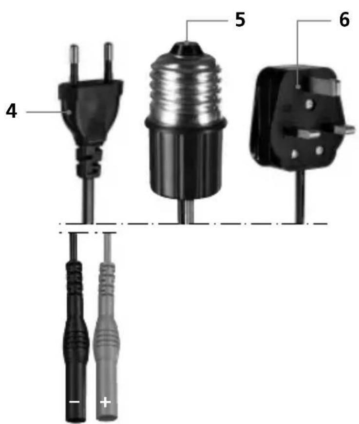
| Included accessories | Euro plug, E27 lamp adapter, UK plug, measuring leads, original measuring adapters |
| Safety | Do not use live in damp conditions; work with caution above 25 V AC / 60 V DC; use only original accessories; disconnect before opening |
| Maintenance and cleaning | Clean and dry the instrument before use; avoid moisture and liquids; store in a dry place |
| Spare parts and repairability | Use only original accessories; modification prohibited; contact customer service for repairs |
Frequently Asked Questions - ACTracer Laserliner
User questions about ACTracer Laserliner
0 question about this device. Answer the ones you know or ask your own.
Ask a new question about this device
Download the instructions for your Measuring equipment in PDF format for free! Find your manual ACTracer - Laserliner and take your electronic device back in hand. On this page are published all the documents necessary for the use of your device. ACTracer by Laserliner.
USER MANUAL ACTracer Laserliner
1 x 9V Block, IEC LR6, Alkali
0^ C - 40^ C
-20°C - 60°C
Read the operating instructions and the enclosed brochure „Guarantee and additional notices" completely. Follow the instructions they contain. Safely keep these documents for future reference.
Function / Application
Cable tracer set with transmitter and receiver
- Fast tracing of coherent electrical circuits.
- Location of lines in coherent, live electrical circuits.
- Detection of fuse circuits in live installations.
- Transmitter power supply directly from power cable to be tested = measurement under operating conditions.
- Socket adapter for direct and fast testing in building installations.
- E27 lamp adapter for direct and fast testing in lamp circuits.
Safety instructions
- The device must only be used in accordance with its intended purpose and within the scope of the specific cations.
- Use only original test adapters.
- Only the original measuring leads may be used. Their voltage, category and ampere rated powers must match those of the measuring device.
- Isolate the device from all current sources before opening the battery compartment cover.
- If possible, do not work alone.
- If you have to take hold of the measuring spikes, do so by the grip sections only. Do not touch the measuring contacts whilst the measurement is being taken.
- Only connect the completely prepared device (transmitter with test leads plugged in) to a power source. First disconnect the electrical circuit from the power supply and only switch on again after wiring work has been completed. Lock the master switch to prevent it being inadvertently switched on.
- If the device comes into contact with moisture or other conductive residue, work must not be carried out under voltage. At and above voltages of 25V AC/60 V DC, the presence of moisture creates the risk of life-threatening electric shocks. Clean and dry the device before use. When using the device outdoors, make sure that the weather conditions are appropriate and/or that suitable protection measures are taken.
- If you are working with voltages higher than 25V AC/60 V DC, exercise extreme caution. Touching the electrical conductors at such voltages poses a risk of life-threatening electric shocks.
-
Do not use the device in environments in which there are conductive particles or where the occurrence of moisture (in the form of condensation, for example) can create transient conductivity.
-
If you are taking measurements in the hazardous vicinity of electrical installations, do not work alone and seek guidance from an electrically skilled person before starting work.
- Before taking any measurements, make sure that both the area to be tested (e.g. a line), the test device and the accessories used (e.g. connection cable) are in proper working order. Test the device by connecting it to known voltage sources (e.g. a 230V socket in the case of AC testing). Stop using the device if one or a number of its functions fails.
- Do not leave the sender running permanently. Only use during actual measurement. After a measurement is taken, the transmitter (including test leads) must be removed from the measured circuit.
- Do not expose the device to moisture or liquids. When using the device outdoors, make sure that the weather conditions are appropriate and/or that suitable protection measures are taken. The measuring tools and accessories are not toys. Keep out of reach of children.
- Do not use the device in environments containing explosive gases or vapour.
- Protect the device against contamination and damage, and make sure it is stored in a dry location.
- The structure of the device must not be modified in any way.
- Please ensure compliance with the safety regulations set out by local and national authorities with regard to the correct and proper use of the device.
Symbols
Hazardous electrical voltage warning: Unprotected live components inside the device housing may pose a risk of electric shock.

Danger area warning

Protection class II: The test device has reinforced or double insulation.
CAT III
Overvoltage category III: Equipment in fixed installations and for applications where specific requirements with regard to the reliability and availability of equipment have to be met, e.g. circuit-breakers in fixed installations and devices used in industrial applications which are permanently connected to the fixed installation.

Important notes. Must be observed.
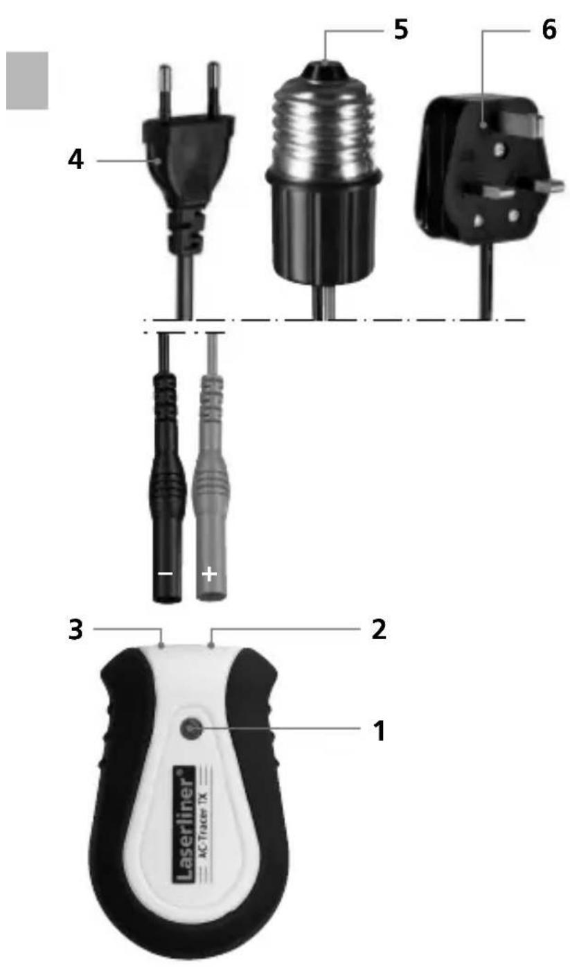
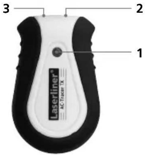
1 ON indicator lamp
2 Connecting socket, red +
3 Connecting socket, black -
4 Euro connector
5 E 27 Lamp adapter
6 UK plug
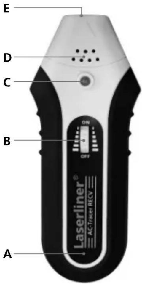
Receiver RECVSender TX
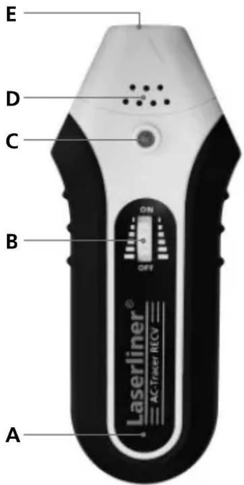
A Battery compartment (rear)
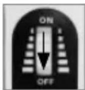
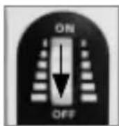
B Rotary ON/OFF switch/ sensitivity setting
C ON indicator lamp
D Speaker
E Sensor head
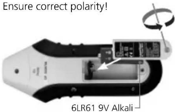
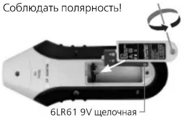
Inserting the battery
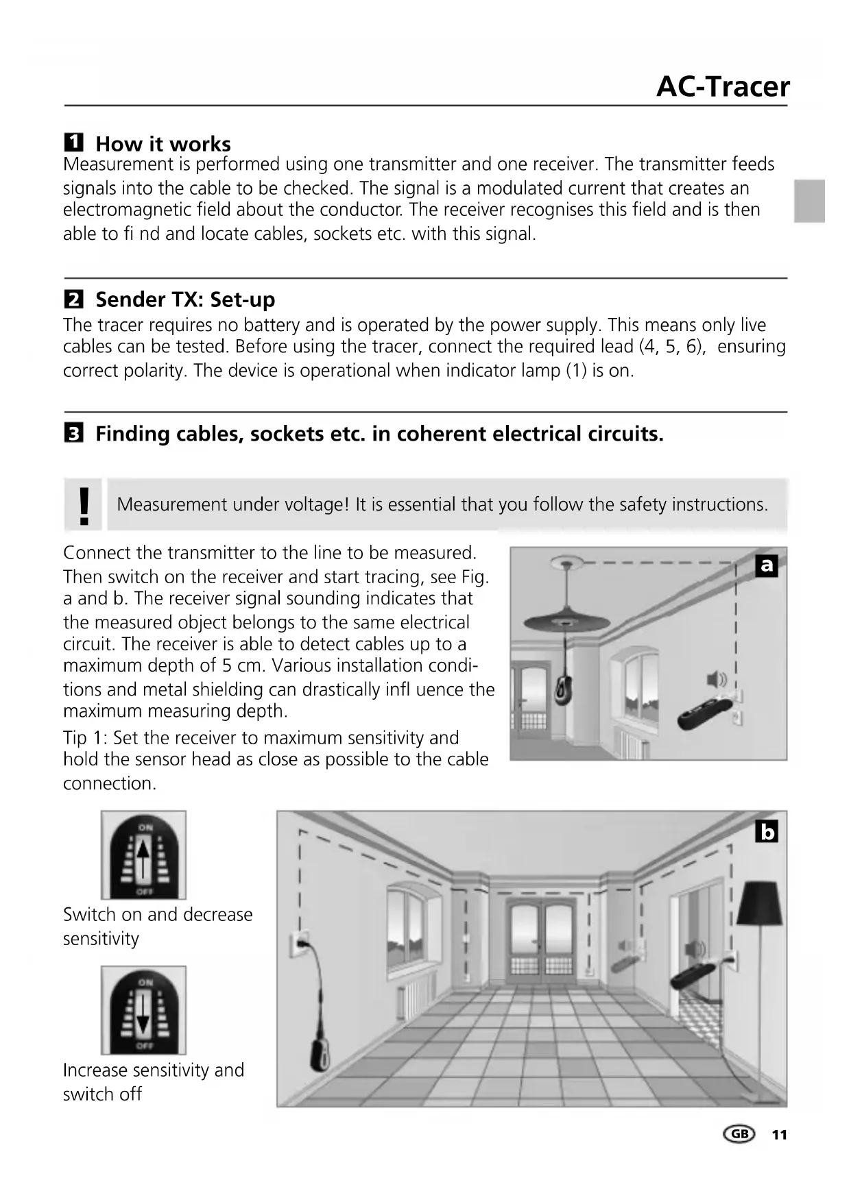
1 How it works
Measurement is performed using one transmitter and one receiver. The transmitter feeds signals into the cable to be checked. The signal is a modulated current that creates an electromagnetic field about the conductor. The receiver recognises this field and is then able to find and locate cables, sockets etc. with this signal.
2 Sender TX: Set-up
The tracer requires no battery and is operated by the power supply. This means only live cables can be tested. Before using the tracer, connect the required lead (4, 5, 6), ensuring correct polarity. The device is operational when indicator lamp (1) is on.
Findings, sockets etc. in coherent electrical circuits.

Measurement under voltage! It is essential that you follow the safety instructions.
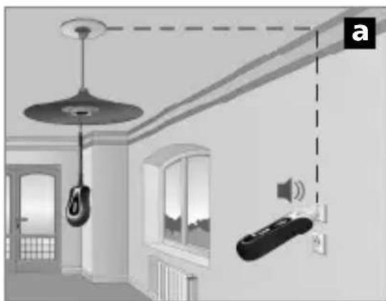
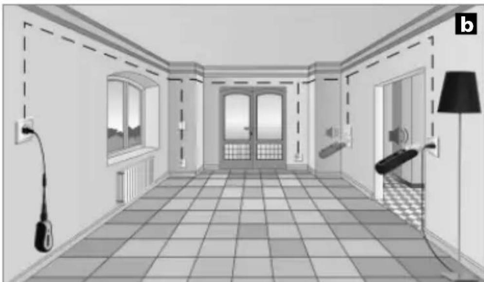
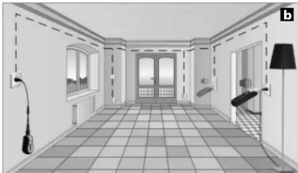
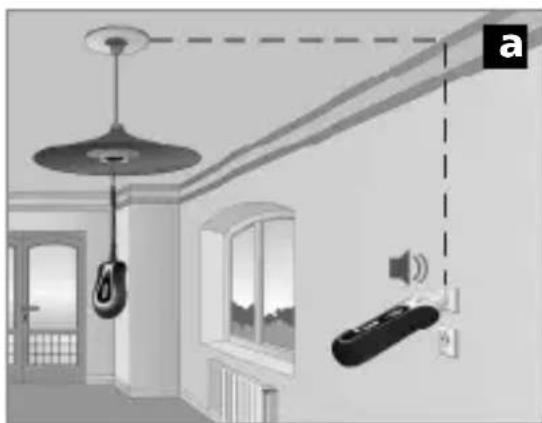
Connect the transmitter to the line to be measured. Then switch on the receiver and start tracing, see Fig. a and b. The receiver signal sounding indicates that the measured object belongs to the same electrical circuit. The receiver is able to detect cables up to a maximum depth of 5cm . Various installation conditions and metal shielding can drastically influence the maximum measuring depth.
Tip 1: Set the receiver to maximum sensitivity and hold the sensor head as close as possible to the cable connection.
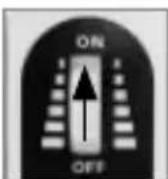
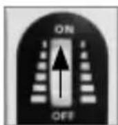
Switch on and decreasesensitivity
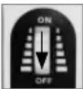
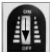
Increase sensitivity and switch off
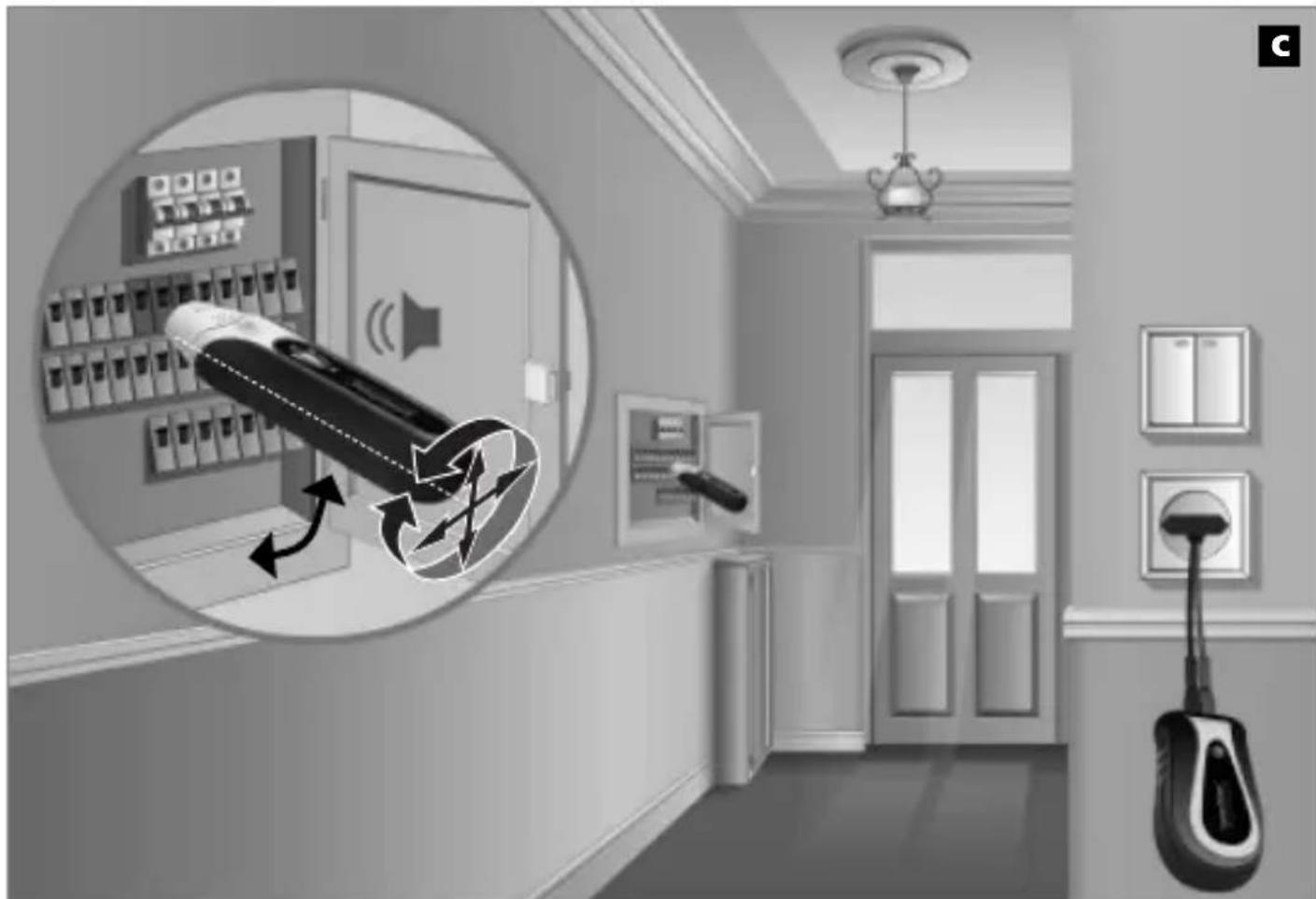
4 Locating fuse circuits
-
Measurement under voltage! It is essential that you follow the safety instructions.
-
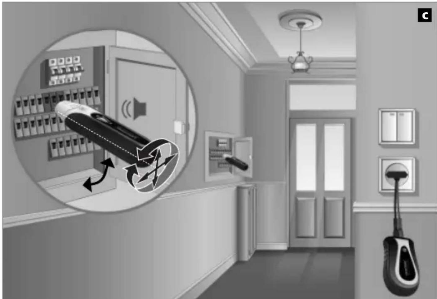
The cover of the fuse box may only be removed by a skilled electrician.
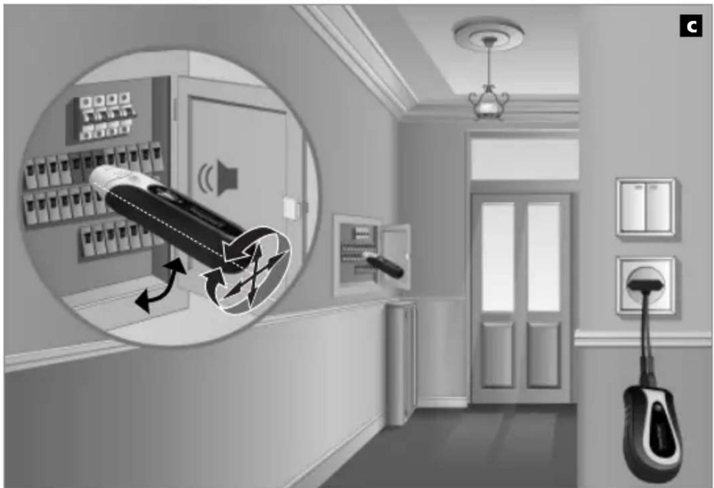
Connect the transmitter to the line to be measured. Then turn on the receiver and start tracing. See Fig. c.
The detected fuse is located in the area where the signal tone of the receiver sounds. Due to different installation conditions (RCD automatic circuit breakers, types of fuses etc.), in most cases it is not possible to precisely locate the fuse but rather only to narrow down the area where it is located.
Tip 2: Decrease the receiver sensitivity in steps in order to closely narrow down the location of the fuse.
Tip 3: Rotate the receiver around its longitudinal axis by 90^ or modify its horizontal and vertical positions. This will adjust the device to different automatic circuit breakers, which have magnetic coils installed in different positions. Re-adapt the sensitivity if necessary.
Technical data
Sender AC-Tracer TX
Nominal voltage
Maximum input voltage
Overvoltage category
Power supply
Operating temperature
Storage temperature
Maximum altitude
Weight
Dimensions (W x H x D)
Receiver AC-Tracer RECV
Measuring range
Power supply
Operating temperature
Storage temperature
Maximum altitude
Weight (incl. battery)
Dimensions (W x H x D)
200-240V
300V AC
CAT III 300V, pollution degree 2
200-240V AC, 50-60 Hz
0^ - 40^
-20°C -60°C
2000 m above sea level
ca. 54 g
50 × 80 × 32 ~mm
0 - 5 cm measuring depth
1 x 9V block, IEC LR6, Alkali
0^ C - 40^ C
-20°C - 60°C
2000 m above sea level
ca. 155 g
68 × 165 × 36 mm
Subject to technical alterations 09.10.
EU directives and disposal
This device complies with all necessary standards for the free movement of goods within the EU.
This product is an electric device and must be collected separately for disposal according to the European Directive on waste electrical and electronic equipment.
Further safety and supplementary notices at: www.laserliner.com/info

Dimensioni (L x A x P)
200-240V
300V AC
Dimensioni (L x A x P)
Dimensoes (L x A x P)
Receptor AC-Tracer RECV
Margem de medicacao
1 x 9V Block, IEC LR6, Alkali
0^ - 40^
-20°C - 60°C
2 000 meter over havet
ca. 155 g
68 × 165 × 36 mm
Tekniska andringar forbehalls 09.10.
1 x 9V Block, IEC LR6, Alkali
0^ C - 40^ C
-20°C -60°C
1 x 9V Block, IEC LR6, Alkali
0^ C - 40^ C
-20°C - 60°C
Co6nOaTb nOJaepHoCTb!
YctaHOBka 6aTapei
1 PpHcHnIeIcTBnI
I3mepenHe BbINOJIHЯETcA NOMOUsbIO NpepaTnKa I npneMnKa. IpepaTnK NOaet CnHaJIbI B npOBepreMyIO JINHIO. CnHaJnpedCTaBJIeT CO6oB MoDyIInpOBAHHbI TOK, CO3dauoUH BOKpyr IPOBOdNka 3JeKtpomarHHTHOe NOJE. PnemHrk paCNo3HaET 3TO POJIe HMOKeT Cero NOMOUsbIO HaxODNTb U yCTaHaBnBaTb MeCTOnOJIoXeHne IpoBODoB, PO3ETOK N.T.D. C NoDAHHbIM CNrHaJOM.
2 NpepaTuk TX:HaiaKa
Прибору He hyжны бата两点, on pa6oTaET OT cetn. ПOTOMy n3MepeHnmoXHO BbIPOHЯТ b TOnbKO Ha npOBoaX, HaxOДЯUxCЯ pOД hAnpJxKeHem.перEDNcPONb3OBaHnEM NOdcoEINHTb hyxHbI KabeIb (4, 5, 6).ПрИ ATOM co6IIOdaTbNoJIpaHocTb. Пriбор pa6oTaET, kOrda rOpNT KOHTpoJIbHaЯ lamna (1).
B POnck npoBOIOB, p03eTOK n T.D. B CB8aHHbIX CNIOBbIX cIeIax.

I3mepeHne noi HanpJxKeHnem! O6aTeJIbHo co6IoJaTb npaBnla TeXnKc 6e3OpacHOCTn.
IopocenHnTb nepeaTnK KImepreMOMy npOBoY. 3aTeM BkIouHTb PpneMHNK Haatb nonck, cm. pnc. a, b. Ecn 3ByuNT akycntueckn CNrHaJ, 3NaHT, o6BeKT N3MepeHn OTHOCNTc K Toj Xe CnilOBoU ceni. PpneMHNK HaxOJT npOBoJa Ha rny6InHe He 60lee 5 cm. MaKc. rny6InHa n3MepeHn CNlbHO 3aBnCnT OT pa3JIuHbIX yCIOBn MOHTaXa I MeTaJInueCKNX kpaHOB.
Cobet 1: YctaHOBntb npneMnK Ha MaKcMaJIbHyIO UyBCTBNTeJIbHOCTb I NOIBeCTN IN3MePNTeJIbHbI

HaKoHeuHnK DaTnKa KaK MoXHo 6JInxKe K MeCTy POnKJIIOueHnKa6eJr.

BKNIOHTbNCHN3NTb 乌BCTBNTeHBOCTb
IOBbICNTb
yBCTBNTeJIbHOCTb N
BbIKJIOuHTb

OrpaHnueHne cepei, 3aunuHbIX npedeoxpaHnteJMa
!
YbIMKHeHHa Ta 3MeHWeHHa UyTnNBOCTi
36iNbWeHnYyTInBOCTiTa BmKHeHH
4 Lokani3aizj kij i3 3ano6ixhknamn
!
- Bvmip πiδ haŋpyroio! O6ob'ra3koBO doTpmyItecBka3iBOK i3 texhikn 6e3neKn.
- 3Himatn Kpnkny Kopo6kn 3aNo6ixHKamm MoXHa IInIe eJekpKam.
Пи'd' endaTe nepeDabau Do BmipIOBaHOJI liHii. NotIM yBIMKHiTb npnMaU i noCHiTB nowyK. NIV. pncyHOK C.
PozkyBaHn 3aNo6ixHK 3hAxOHTbCtAM,Je LyHaC 3ByKOBn CnHaI npiMaaya.
Yepe3 pi3HiyMOBn MOHTaKy (aBTOMATN 3axnCTy BiD CTpyMIB 3AMKahHna 3eMJIIO, TINI 3anobixHKIB TOO) y 6iNbwoCTi BnuaKIB HEmoXJIbBO BN3HaHTN TOUHe MicuIOnIOxKeHHraPO3wkyBaHO rO 3anobixHnKa, a MoXHa IInIe O6MeJNTn DInrHky, Ha KIK BIn 3HaxODITbcra.
Iopada 2: 06 Tohne Bn3NaHTM MiceNoJxHn P03yKbHOro 3anobira, noctynoBO 3MeHwyTe UytTnBicTb npnMaHa.
Iopada 3: OseptaTe npiMaU Ha 90^ HABKOLO NO3IOBXHbOoi oci a6o 3MiHouTe roPn3OHTaJIbHe Ta BepTkaJIbHe NpIoXeHHra, 1o6 npicCTOCyBaTn npiJaIdo pizHX aBTOMaTHuHNx 3aNo6ixHKiB, kki MaOTb KOTySKNe eJeKtpOMaHrHiTiB y pi3Hnx MOHTaJHX npIoXeHHax. Ppr Heo6xIDHOCTI 3HOBy halaSTyIte ChTINBICTb.
TexhiHi daHi
Vysilac AC-Tracer TX
Jmenovité napétí
Prijima AC-Tracer RECV
Rozsah měření
Napajeni
Pracovni teplota
Skladováci teplota
1 x 9V Block, IEC LR6, Alkali
0^ C - 40^ C
-20°C - 60°C
2000 m peste NN (nul normal)
cca. 155 g
68× 165× 36mm
Ne rezervam dreptul sa efectuam modificari tehnice 09.10.
Prevederile UE.si debarasarea
Hnctpykun 3a 6e3oNaCHOCT
- I3noI3BaIte npi6opa eINHCTBeHO CbIaCHO npeHa3HaueHneTo 3a yNoTpe6a B paMKnte Ha cneuΦnkaunTe.
- I3nOJ3BaIte eDINHCTBeHO opINHaJIHHaNHaI3MePBATeJIeH aJaITep.
- I3noJI3BaIte eINHCTBeHO opINHaJIHnTe n3MePBATeJIHn JInHn. Te TpI6Ba da npITexKaBaT KopeKTHN HOMHaJIHn MOUHOCn Ha HApEKeHne, KaTeOpnI N TOK KaKTo Ha n3MePBATeJIHnI npIbOp.
-прешида 6бде OTВОЕн KaNAKьТ Ha ГеЗДОТо Ha 6aTeРЯТа, пиборьТ trяБВа дa 6ьдe pa3eINHeH OT BCNUKИ N3TOUHNUHa TOK. - No Bb3MOXHOCT He pa6OTe camn.
- XBaUaIte I3MepBaTeJIHITe eJekTPOi CaMO 3a pBkoXBaTKITE. I3MepBaTeJIHITe KOHTaKTn He TpRAbA da ce IOKOCBat IO BpeMe Ha I3MepBaHaTo.
-ПпсьeдияВаite edHCTBeHO haIbJIHO NOIrotBeHOTO yCTpoiCTBO (прdaBaTeJ CnoCTaBeHIn 3MepBaTeHnnpOBODHn) KbM n3TOUHNK Ha HApEgeHne. Прdi TOBa npeBkIIOyeTe TOKOBaT a BepnTa da 6bde cBO6OHa OT HApEgeHne n eDBA cIeJ OKa6eJIyBaHETO BKIOUeTe OTHOB.OcIrpyte rnaBnI ppeKbcBauchpeu HeyKeJaHO NOBtOpHO BKIOUHaHe OT TpeTo Niue. - Ako npnbopbTe oBnaJxHe n C BlaRa nIyI npOBoJaIIOCTaTbI, He Tp8Ba da ce pa6oTHn oIaHapexeHne. OT hApexeHne 25V AC sbOTBeTHo 60V DC nopAaN Blaarata cblaeCTByBa NOBnSeHa onaCHOCT OT ONaCHN 3a JKBOTA TOKOBn ydApn. NOnCTe I N3CyUWe Te np6opa npEn Da r OIN3PON3BaTe. Pnp IN3PON3BaHe HABbH OsbPHeTe BHNMaHne yCTPOiCTBOTo Da Ce IN3PON3Ba CaMo PnCsbOTBeTHn MeTeOpOJIoNHyH NcNoBn, CbOTBeTHo Pn IOXODaIz 3aUnTHn MEPKn.
-
Пи бораве с наржени по-Bисоки OT 25V AC сьотьетно 60V DC Тябва за ce Bимма в особен. Пи дOKOCbaHe Ha eilektrpnieckn пювдни рп Te3и наржени Beue CBшесТВуВа ONaCHOCT 3aЖИВОТа поради TOKOB удap.
-
He n3pOJI3BaIte yCTpoIcTBaTa B o6KpbJxHnIe, KOINTo ca 3apeHEn OT npOBODIu ChAChIIN IINB KONTO MoKe Da Ce CTInHe Do BpeMeHHa pOBODIMOC TopaI IN Bb3HNKBAUa BlaXHOCT (HaPpIMep nopadN KOHDeH3aUy).
- He n3BbRbBaIte cam n3MepBaHnB B ONaCHa 6n3OCT do eJekTpueckn INHCTaJaun, a cAmO CJIeD INHCTpyKtIpaHe OT OTROBOpHnE JekTpOTexNk.
- YBepTe Ce npeIN BcAko N3MepBaHe, Ye N3MepBaHaTa o6NaCT (HaNPIMep IpoBOdHnK), N3PNTaTeHNrT pnp6Op IN3PON3BaHnTE aKceCoapn (HaNPIMep CBp3BaU, IpoBODnK) Ce HAMnPAT B 6e3ynpueHNo CbCToRnHe. PpOBepTe np6Opa Ha N03HaTN N3TOuHnCn Ha HAppeKeHne (HaNPIMep 230 V-5eIeJIHa po3eTKa 3a AC-TeCTBaHe). Pnp6OpbT He Tp86Ba Da ce IN3PON3Ba NoBeYe, aKO eDNa INII HAKOJI K OYHKUIN OTKaJkAT.
- He u3noJ3BaIte u3JIbUbaTeIa B HeIpeKbCHaT peXIM Ha pa6Ota, a cAmO 3a BpeMeTO Ha CbIuHcKOTo u3MepBaHe. CJeIu3MepBaHe npEJaBaTeIaT (BkI. u3MepBaTeIHH npOBOnHnI) Tp8Ba Da 6bIe OTCTpaHeH OT u3MepBaHaTa BepnIgA.
- YpeIbT He TpIbBa Da 6bIe N3JIaRaH HITO Ha BlaIa, HITO Da BnI3a B CbIprNKOCHOBeHne C TeuHocTn. Iprn N3PON3BaHe Ha OTKpITo o6pbUaIte BHNMaHne, Ye C ypeJa MoKe Da ce pa6OTn CaMO IprN CbOTBETHm MeTeOpOJIoTNH uCIOBnA peCn. Iprn POnXoJUzN 3aUHTHm MepKn.
-Измерва teлнite урediиnpiHaIeJxHocHTte He ca nIrpauKn 3a Deua.Да ce cBxpaHЯВaT Ha MRCTO, HeIOCTbПHO 3a Deua. - Pn6opbT He TpaBa Da ce n3POn3Ba B O6KpbXeHna CB3pNBOONaCHn Ra3OBe nn napn.
- Pana3eTe npnbopa OT 3aMbpcBaHnI IOBpeN I rO CbXpaHraBaYTe Ha Cyxo Macto.
-Приборьт He Тябва за се поменя KOHCTpyKTHBHO. - MoЯ пидьржай Te ce KbM Меркite 3a 6e3ОпаСоCT Ha MeCTHи HaциОнHiN opraHn 3a npaBvIHHOTO n3ПОЛЗВаНe Ha yCtpoICTBOTO.
CIMBOJN
IpeynpejdeHne 3a onacno eJektpueecko HanpejxeHne: Iopadn He3aunTeHN TOKOpnoBODaN KOMNoHENTN BbB BbTpEshOCTTa Ha KopnyCa MOKe Da Bb3HnKHe IOCTaTbUHa ONaCHOCT Xopa Da 6bDaT n3IoJKeHn Ha pNcKa Ha eJektpueeCKn (TOKOB) yIap.

PpeDynpexKdEHNHe 3a onaCHO MrcTo

Klaac Ha 3aunTa II: TcepebT npTeXaBa ycIneHa IIN DBOHa n3OJaIaIy.
CAT III
KateropnHa npebuheHo hanegeHne III:TexnoIouHn cpeCTBa BvB _IKCnpaHn nHCTaJauuN IN TaKbA CnyaN, B KOnTO Ce NoCTABRT CneuaHn N3NCKBaHn KaM HaeXdHOCTTa I rOToBHOCTTa 3a pa6Ota Ha TexnoIouHnTe CpeCTBa, HApnPmep npeKbCBaU BbB _IKCnpaHn nHCTaJaUuN uYcTPOHCTBa 3a INDyCTpNaJIHa yNotpe6a C NOCToRHHO CBbp3BaHe KbM _IKCnpaHn aHaTHCTaJaUa.

Baxhny yka3aHn, KOnto 3aIbJxNtJIHo Tp8Ba da ce B3eMaT IOd BHImaHne.
1 Pa6oTHa lamna
2 CbeHnTeHa 6yKca YepBeHa +
3 CbeHnTeHa 6yKca cepHa -
4 Ebroo-uekep
5 E27naMnoBaandaTep
6 UK-uekep (3a BeInko6pnTaHnA)
ПриематEN RECVN3nb4BaTe
A THe3do 3a 6aTeepn (o6paTHa cTpHa)
B BKJ/N3KJI BbptaI npeBKJIIOUyBaTeI / HacTroPoiKa Ha YyBCTBNTENHOCT
C Pa6oTHa JAmna
D BncoKOrOBOpnteI
E CeH3OpHa rIaBa
Ia ce o6pbuza BnMaHne Ha npabunnnnoJpntet!
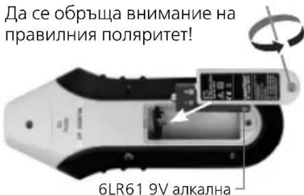
Посраваян ha 6aTepyra
1 Пинцин на pa6ota
I3mepBaHTo Ce n3BbPbBa C eINn PpeaBaTeJ N eINn PpneMnK. PpeaBaTeJrTPOda CBnHaJI N B PPOBODnKa, KOITo Tp6Ba Da c ce npOBepn. CnHaJIbT e MOdyInpaHTOK, KOITo PpOu3BexJa eJeKtpomarHHTHO NOJe OKOJO PPOBODnKa. PpneMnKbTpa3No3HaBa NoJeTo, N TaKa MoKe Da HaMeRn N JOKaJIu3nPa PPOBODnCHTe, UeNcEJIHNTe rHe3Da N Dp. C NoDAJeHnra CnHaJI.
2 ɪзльчытел TX: Okomплькован.
UcpoCTBOTo He ce HxJae ot 6aTePnI n ce 3axpaHb a OT en. MpeXkata. CneIOBaTeHNO MoKe Da ce N3BbPbWbAT N3MepBaHncaMo Ha HAMnpaSic Ce NOd HAppeXHe NPOBOHnCi. PpeNi N3NoJ3BaHeto pncBeDInHeTe JKeHaHnKa6en (4,5,6). PprTOBa ce yBepTe B npaBnHaTa IOnJrPHoCT. UcpoCTBOTo pa6OTn, KOrato KOHTpOHaTaNamna (1) cBETn.
B CBbP3aHn TOKOBn BepnHaMepeTe npoBOdHuCi, UeIcEHNrHe3da n dp.

I3mepBaHe noiHaPexEne! 3aIbJxNteHNo da ce cna3BaT yKa3aHnraTa 3a 6e3OpacHOCT.
CbpxeTnpedaBateT KbM N3MepBaHnI npOBoHNK. Cnei TOBa BKIOUcTe pIneMHNka N 3aIOuHHe TbpcHeTo, BHXTe fNpya a,b. N3MepBaHnI To6eKT Ce Yncn KbM CbUaTa TOKOBA Bepnra, KOrATo Ipo3Byu CNrHaJIHNrTOH Ha npiemHnKa. PIneMHNKbT HAMnpa IpoBOHDnCuI Do IIbIoOUnHa MaKc.5 cm. Pa3NIuHn ycNoBna Ha BrpaXdaHe N MeTaJIHn ekpaHnPaHnry MoKe Da BLOUaT CINHO MaKcIMaHnA Ta IIbIoOUnHa Ha N3MepBaHe.
CbBET 1: NocTaBeTe npHemnka Ha Hau-BncoKa CyBCTBNTeJIHOCT IN pN6JInxKeTe ceH3OpHaTa rIaBa Bb3MOxHO Ha-6JIN3O Do n3BOJa Ha Ka6eJa.
BkIIOUBaHe HamaJIaBaHe Ha CyBCTBNTJHOCTTa
IobuBaHe Ha YBCTBNTJIHOCTTa N 3KJIIOUBAHe

4 Pa3rpaHnUaBaHe Ha 3aIHTeHn BepuRn
!
-Измерване пон haорженье! 3адьлжително за спаЗВаТ yka3aHЯТа 3a 6e3ОпаСНоCT.
- POKPITNeTo Ha KyTnTa C npEa3nteN Tp8Ba Da ce OTcTpaHn cAmO OT eNEKTPocneuaJIInCTn.
Cbpxte npedaBateJ KbM n3MepBaHn npoBODnK. CneT OBa ce BkIouBa npneMHnkT n ce 3aNoCb c TbpceHeTo. BxTe fNrgpa c.
TbpcHnT npOBODnK ce HAMnpa B 3OHaTa, B KOrTO npo3ByuBa CNrHaJIHnT ToH Ha npneMnka. Iopadn pa3nnHnTe yCNOBnHa nHCTaIauZn (RCD aBTOMaTn, BnIOBe eJ. npedna3nteNn Irp.) B NOBeUeTo CnyuAn TbpcHnT eJ. npedna3nteN He MoXe da ce JOKaIIIN3nPa TOUHO, a cAmO Da Ce OgrAHuN 3OHaTa, B KOrTO ce HAMnpa Toi.
CbBET 2: HamaIeTe NoCTeHNO UyBCTBHTeJIHOCTTa npn npneMHnka, 3a da orpaHnHTe no-dO6pe TbpcHn eJ. npedna3nteJ.
CbBET 3: Приемателота се заврtn Ha 90^ no habлбхнота oc pecn. Да се Измен XopиэHTaHOTO и ВертукалHOTо поожене, 3a Да се пacheуpeдт Кьм pa3linuHNTe 3auntnпpeкьсвачи, контимат различни пооженя Ha Bb36ydnteHNTe 6o6HHI. При hyжда OTHOBO harlaceteЧУВСТВИТЕНHOCCTTа.
TexHnueckxapaKTepeNCTnKn
Изльчbatел AC-Tracer TX
HOMnHaJIHo HAppeKeHne
MaKcImaJIHo BxOJHo HappeKeHne
MaKcImaJIHa pa6OTHa BnCoUHa
TeTIO
Pazmepn (XxBxD)
200-240V
300VAC
CAT III 300V, cTepeH ha 3aMbpcBaHe 2
200-240V AC, 50-60 Hz
0^ C - 40^ C
-20°C - 60°C
2000 M haM MOpCKOT paBnIe
ok.54g
50 × 80 × 32 ~mm
ПриематEN AC-Tracer RECV
MaKcImaJIHa pa6OTHa BnCoUHa
Tergo (BkI. 6aTepey)
Pa3mepn (LxBxD)
0-5cmДьлбоуннаHa n3Meрванe
1x9V6Jok,IECLR6,aJIkaJIHa
0^ C - 40^ C
-20°C - 60°C
2000 M haM MOpCKOTo paBnIe
ok. 155 g
68 × 165 × 36 ~mm
3ana3Ba ce npaBTo 3a TexHnueckn n3MeHeHn 09.10.
EC-pa3npope6n n n3XbpyrJHe
UpeIbT N3IIJIHЯBa BCnUKN Heo6XODIMN CTaHdApTN 3a CBO6OJHO DBNXeHne Ha cTOKN B paMKITE Ha EC.
To3n npoJyKT e eJekTpueckn ypei n Tp8Ba Da ce c6bnpa N 3Xbprna CbIaCHO eBpOeNcKaTa DnpeKtNbA OTHOCHO OTpaIbUnte OT eJekTpuecko I eJekTpoHNO o6OpuDbAhe (OEEO).
Оше Инструкшии за бezоноасноct и довьлнгелни уka3aHHЯ ще наимпту haадPEC: www.laserliner.com/info

! i c oyniec xepioou kai to ouvnmuévo teuxoc ,Ynoedεic Eyyunonc kai npoOtec unoδeic. Tpeite tic avaepopoevec odnyiec. DuαoσeT E πpooxñ auta ta éyypaqa.
- Function / Application
- Safety instructions
- Symbols
- CAT III
- How it works
- Sender TX: Set-up
- Findings, sockets etc. in coherent electrical circuits.
- Locating fuse circuits
- Technical data
- Sender AC-Tracer TX
- Receiver AC-Tracer RECV
- EU directives and disposal
- Receptor AC-Tracer RECV
- PpHcHnIeIcTBnI
- NpepaTuk TX:HaiaKa
- B POnck npoBOIOB, p03eTOK n T.D. B CB8aHHbIX CNIOBbIX cIeIax.
- OrpaHnueHne cepei, 3aunuHbIX npedeoxpaHnteJMa
- Lokani3aizj kij i3 3ano6ixhknamn
- TexhiHi daHi
- Vysilac AC-Tracer TX
- Prijima AC-Tracer RECV
- Prevederile UE.si debarasarea
- Hnctpykun 3a 6e3oNaCHOCT
- CIMBOJN
- Пинцин на pa6ota
- ɪзльчытел TX: Okomплькован.
- B CBbP3aHn TOKOBn BepnHaMepeTe npoBOdHuCi, UeIcEHNrHe3da n dp.
- Pa3rpaHnUaBaHe Ha 3aIHTeHn BepuRn
- !
- TexHnueckxapaKTepeNCTnKn
- Изльчbatел AC-Tracer TX
- ПриематEN AC-Tracer RECV
- EC-pa3npope6n n n3XbpyrJHe
Brand : Laserliner
Model : ACTracer
Category : Measuring equipment