
GPB 12V Professional - Battery BOSCH - Free user manual and instructions
Find the device manual for free GPB 12V Professional BOSCH in PDF.
| Product type | Lithium-ion battery for job site radio |
| Brand | Bosch |
| Model | GPB 12V Professional |
| Nominal voltage | 12 V |
| Weight (depending on battery) | 1.6 – 1.9 kg (according to EPTA 01:2014) |
| Charging temperature range | 0 °C to +45 °C |
| Operating temperature range | -10 °C to +40 °C |
| Storage temperature range | -20 °C to +50 °C |
| Compatible batteries | GBA 10.8 V…, GBA 12 V… |
| Recommended chargers | AL 11…CV, GAL 12…CV |
| Mains power supply (unit) | Input 100-240 V~, 50/60 Hz, output 12 V / 1.5 A |
| Audio functions | FM/AM radio, AUX input, equalizer, bass/treble adjustment |
| Display | Screen with frequency, charge status, time |
| Controls | On/Off, volume, source selection, memory buttons |
| Backup batteries | 2 x 1.5 V LR03/AAA (not supplied) |
| Care and cleaning | Clean with a soft, damp cloth, without detergents or solvents |
| Safety | Do not expose to moisture or rain, do not open the battery, use only Bosch chargers |
| Spare parts and repairability | Power supply unit and replacement cable available, repair by an authorized Bosch service center |
Frequently Asked Questions - GPB 12V Professional BOSCH
User questions about GPB 12V Professional BOSCH
0 question about this device. Answer the ones you know or ask your own.
Ask a new question about this device
Download the instructions for your Battery in PDF format for free! Find your manual GPB 12V Professional - BOSCH and take your electronic device back in hand. On this page are published all the documents necessary for the use of your device. GPB 12V Professional by BOSCH.
USER MANUAL GPB 12V Professional BOSCH
OHJ H1C1-2915-001 Bank Page 1 Friday, July 29, 2016 3:21 PM
Robert Bosch Power Tools GmbH
70538 Sutw
GERMANY
www.bosch-pt.com
160992A2NA2016.071175

160992A 2NA
GPB 12V-10 Professional
HEAVY
BUTY

BOSCH
GBA 12V...GAL 1230 CV (12,0 V)
GAL 1215 CV (3,6-12,0 V)

GPB 12V-10
5
6 | Deutschland
Deutsch
Sicherheitshinweise
WARNING
Read all safety warnings and all instructions, including the information on the
rear of the construction site radio. Failure to follow the warnings and instructions may result in electric shock, fire and/or serious injury.
Save all safety warnings and instructions for future reference.
The term "construction site radio" used in the safety notes refers to mains-powered construction site radios (with power-supply plug) and to battery-operated construction site radios (without power-supply plug).
- Keep work area clean and well lit. Cluttered or dark areas invite accidents.
The mains plug of the power-supply plug must match the socket outlet. Never modify the plug in any way. Do not use adapter plugs together with construction site radios. Unmodified plugs and matching outlets will reduce the risk of electric shock.
Do not misuse the cord of the power-supply plug to carry the construction site radio charger, hang it up, or for pulling the plug out of the outlet. Keep the cord away from heat, oil, sharp edges or moving parts. Damaged or entangled cords increase the risk of electric shock. - Completely unwind the connection cable of the power-supply plug when operating the construction site radio via mains supply. Otherwise the connection cable can heat up.
Take care that the mains plug can be pulled at any time. The mains plug is the only possibility to disconnect the construction site radio from the mains supply.

Protect the construction site radio from rain and moisture. The penetration of water into the construction site radio increases the risk of electric shock.
- Keep the construction site radio and the power-supply plug clean. Contamination may result in danger of electric shock.
- Check the construction site radio, power-supply plug, cable and plug each time before using. If damage is detected, do not use the construction site radio. Never open the construction site radio or the power-supply plug yourself, and have repairs carried out only by a qualified repair person using only identical replacement parts. Damaged construction site radios, power-supply plugs, cables and plugs increase the risk of electric shock.
This construction site radio is not intended for use by children and persons with physical, sensory or mental limitations or a lack of experience or knowledge. This construction site radio can be used by children aged 8 or older and by persons who have physical, sensory or mental limitations or a lack of experience or knowledge if a person responsible for their safety supervises them or has instructed them in the safe operation of the construction site radio and they understand the associated dangers. Otherwise, there is a danger of operating errors and injuries.
Supervise children during use, cleaning and maintenance. This will ensure that children do not play with the construction site radio.
Do not open the battery. Danger of short-circuiting.
Bosch Power Tools 1609 92A 2NA| (29.7.16)


12 | English

Protect the battery against heat, e. g., against continuous intense sunlight, fire, water, and moisture. Danger of explosion.
When battery pack is not in use, keep it away from other metal objects like paper clips, coins, keys, nails, screws, or other small metal objects that can make a connection from one terminal to another. Shorting the battery terminals together may cause burns or a fire.
Under abusive conditions, liquid may be ejected from the battery; avoid contact. If contact accidentally occurs, flush with water. If liquid contacts eyes, additionally seek medical help. Liquid ejected from the battery may cause irritations or burns.
In case of damage and improper use of the battery, vapours may be emitted. Ventilate the area and seek medical help in case of complaints. The vapours can irritate the respiratory system.
- Recharge only with the charger specified by the manufacturer. A charger that is suitable for one type of battery pack may create a risk of fire when used with another battery pack.
Only use the battery in conjunction with your construction site radio and/or a Bosch power tool. This is the only way to protect the battery against dangerous overload.
The battery can be damaged by pointed objects such as nails or screwdrivers or by force applied externally. An internal short circuit can occur and the battery can burn, smoke, explode or overheat.
Read and strictly observe the safety warnings and working instructions in the operating instructions of the tools that you connect to the construction site radio.
Product Description and Specifications

Read all safety warnings and all instructions. Failure to follow the warnings and instructions may result in electric shock, fire and/or serious injury.
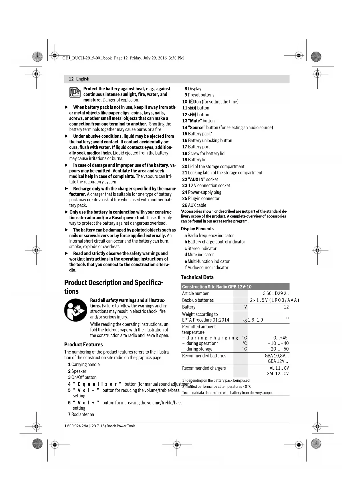
While reading the operating instructions, unfold the fold-out page with the illustration of the construction site radio and leave it open.
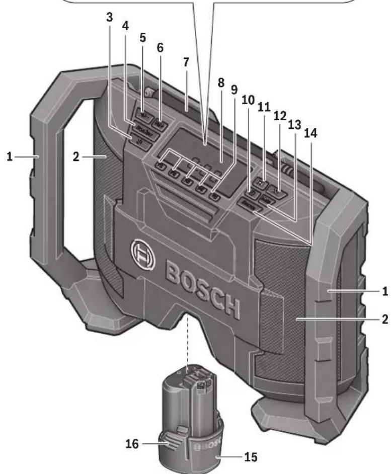
Product Features
The numbering of the product features refers to the illustration of the construction site radio on the graphics page.
1 Carrying handle
2 Speaker
3 On/Off button
4 "EquaIzer" button (for manual sound adjust)
5 "Vol-" button for reducing the volume/treble/bass setting
6 " Vol + " button for increasing the volume/treble/bass setting
7 Rod antenna
8 Display
9 Preset buttons
10 button (for setting the time)
11 spot button
12 button
13 "Mute" button
14 "Source" button (for selecting an audio source)
15 Battery pack*
16 Battery unlocking button
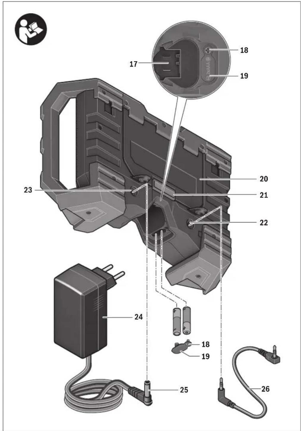
17 Battery port
18 Screw for battery lid
19 Battery lid
20 Lid of the storage compartment
21 Locking latch of the storage compartment
22 "AUX IN" socket
23 12 V connection socket
24 Power-supply plug
25 Plug-in connector
26 AUX cable
*Accessories shown or described are not part of the standard delivery scope of the product. A complete overview of accessories can be found in our accessories program.
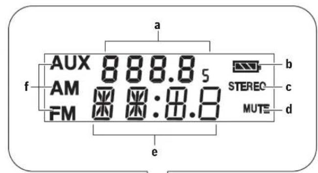
Display Elements
a Radio frequency indicator
b Battery charge-control indicator
c Stereo indicator
d Mute indicator
e Multi-function indicator
Audio-source indicator
Technical Data
| Construction Site Radio GPB 12V-10 | ||
| Article number | 3601 D29 2.. | |
| Back-up batteries | 2 x 1.5 V (LRO3/AAA) | |
| Battery | V | 12 |
| Weight according to EPTA-Procedure 01:2014 | kg 1.6-1.9 | 1) |
| Permitted ambient temperature | ||
| - during charging | °C | 0...+45 |
| - during operation2) | °C | -10...+40 |
| - during storage | °C | -20...+50 |
| Recommended batteries | GBA 10,8V... | |
| GBA 12V... | ||
| Recommended chargers | AL 11..CV | |
| GAL 12..CV | ||
1) depending on the battery pack being used
2) Limited performance at temperatures < 0^
Technical data determined with battery from delivery scope.
English | 13
| Construction Site Radio | GPB 12V-10 | |
| Audio Operation/Radio | ||
| Operating voltage | ||
| - for operation with power-supply plug | V | 12 |
| - for battery-pack oper-a-tion | V | 12 |
| Rated output of amplifier(for operation with power-supply plug) | 2 x 5 W | |
| Reception range | ||
| - FM | MHz | 87.5-108 |
| - AM | kHz | 531-1602 |
| 1) depending on the battery pack being used | ||
| 2) limited performance at temperatures <0°C | ||
| Technical data determined with battery from delivery scope. | ||
| Power-supply plug | |
| Article number 1600 A00 0.. | |
| Input voltage | V~ 100-240 |
| Frequency | Hz 50/60 |
| Input current | mA 500 |
| Output voltage | V= 12 |
| Output current | mA 1500 |
| Weight according to EPTA-Procedure 01:2014 | kg 0.20 |
| Protection class | ☐ /II |
Assembly
Power Supply of the Construction Site Radio
The power supply of the construction site radio can take place via the power-supply plug 24 or via a lithium-ion battery 15.
Operation with Battery Pack
Note: Use of batteries not suitable for the construction site radio can lead to malfunctions of or cause damage to the construction site radio.
Note: The battery pack is supplied partially charged. To ensure full capacity of the battery pack, completely charge the battery pack in the battery charger before using for the first time.
- Use only the chargers listed in the technical data. Only these chargers are matched to the lithium-ion batteries permitted for use in your construction site radio.
The lithium-ion battery can be charged at any time without reducing its service life. Interrupting the charging procedure does not damage the battery.
Insert a battery into the battery port 17 in such a manner that the connections of the battery face against the connections in the battery port 17, and allow the battery to engage in the battery port.
The battery charge-control indicator b appears on the display as soon as a battery pack with sufficient voltage is inserted and the construction site radio is not connected to the mains supply via the power-supply plug 24.
The battery charge-control indicator b indicates the current battery pack status. When the battery charge-control indicator flashes, the battery pack must be charged.
| Indication | Capacity |
| ≥2/3 | ≥1/3 |
| <1/3 | Reserve |
| Battery pack empty | |
To remove the battery pack 15, press the unlocking buttons 16 and pull the battery pack out of the battery port 17.
Operation with Power-supply Plug
Observe the mains voltage! The voltage of the power source for the power-supply plug must correspond with the data on the type plate of the power-supply plug.
Open the protective cap of the 12 V connection socket 23. Insert the plug-in connector 25 of the 12 V power-supply plug into the 12 V connection socket 23. Connect the power-supply plug to the mains supply.
Use only the original Bosch power-supply plug intended for your construction site radio. This measure will ensure proper operation of the construction site radio.
After removing the plug-in connector, reattach the protective cap of the 12 V connection socket 23 to protect against dirt/debris.
When not using the power-supply plug 24, it can be stored in the storage compartment of the construction site radio. For this, disengage the locking latch 21 and open the lid 20 of the storage compartment.
Inserting/Replacing the Back-up Battery
In order to store the time in the construction site radio, backup batteries have to be inserted. Using alkali-manganese batteries is recommended for this purpose.
To open the battery compartment, loosen screw 18 and remove battery lid 19. Insert the back-up batteries. When inserting, pay attention to the correct polarity according to the representation on the outside of the battery lid.
Mount the battery lid 19 again and tighten it with screw 18. Replace the back-up batteries when the time indication e becomes weaker and the construction site radio no longer stores the time.
Always replace all batteries at the same time. Only use batteries from one brand and with the identical capacity.
- Remove the back-up batteries from the construction site radio when not using it for longer periods. When storing for longer periods, the back-up batteries can corrode and discharge themselves.
14|English
Operation
Protect the construction site radio against moisture and direct sunlight. The construction site radio is suitable only for indoor use.
Audio Operation
Switching On and Off
To switch on the construction site radio, press the On/Off button 3. The display 8 goes on and the last set audio source after switching off the construction site radio is activated.
Note: When operating the first time via battery pack or when not having used the construction site radio for a longer period, it may be necessary to press the On/Off button 3 several times or longer, to switch the radio on.
Each time after pressing a button, the display 8 is illuminated for several seconds.
To switch off the construction site radio, press the On/Off button 3 again. The current audio source setting is stored.
To save energy, only switch the construction site radio on when using it.
Adjusting the Volume
After switching on the construction site radio, a mean volume level (value 10) is always set.
To increase the volume, press the "Vol +" button 6; to reduce the volume, press the "Vol -" button 5. The volume setting
"VL" is indicated with a value between 0 and 20 for a few seconds in indicator e on the display.
Before adjusting or changing a radio station, set the volume to a lower setting; before starting an external audio source, set the volume to medium.
The sound can be switched off by pressing the "Mute" button 13. To switch the sound on again, either press the "Mute" button 13 once more or either of the "Vol +" 6 or "Vol -" buttons 5.
Adjusting the Sound
An equalizer is integrated in the construction site radio for optimal sound reproduction.
To manually change the bass level, press the "Equalizer" button 4 once. "BA" is indicated on the display along with the stored bass level value in the multi-function indicator e. To manually change the treble, press the "Equalizer" button 4 again; "TR" as well as the stored treble value are indicated in the multi-function indicator e.
The bass and treble levels can be adjusted between -5 and +5. To increase the indicated value, press the "Vol +" button 6; to lower the value, press the "Vol -" button 5. The changed values are automatically stored when indicator e changes back to the time indication a few seconds after last pressing either of the buttons.
Selecting an Audio Source
To select an audio source, press the "Source" button 14 until the indicator f for the desired internal audio source (see "Setting/Storing Radio Stations", page 14) or for the desired external audio source (see "Connecting External Audio Sources", page 14) is indicated on the display:
-FM:FMRadio,
-“AM”:AM radio.
"AUX": external audio source (e.g. CD player) via the 3.5 mm socket 22.
Setting the Rod Antenna
The construction site radio is provided with a mounted rod antenna 7. For radio operation, point the rod antenna toward the direction that enables the best reception.
When the reception is insufficient, position the construction site radio at a different location that enables better reception.
Note: When operating the construction site radio in the direct vicinity of radio-communication equipment or radio transceivers, or other electronic equipment, the radio reception can be subject to interference.
Setting/Storing Radio Stations
Press the "Source" button 14 until "FM" is indicated for the ultra-short wave reception range or "AM" for the medium wave reception range in display element f.
To set a certain radio frequency, press the seek button 12 to increase the frequency or the seek button 11 to decrease it. The current frequency is shown in indicator a on the display.
To scan for radio stations with a high signal strength, press and briefly hold the seek button 12 or the seek button 11. The frequency of the found radio station is shown in indicator a on the display.
When the reception of a suitable signal is sufficiently strong, the construction site radio automatically switches to stereo reception. The indicator for stereo reception c appears on the display.
To store a set station, press one of the preset buttons 9 for 3 seconds. As soon as "PR" and the number of the selected preset button appears in display element e, the station is stored.
A total of 5 FM and 5 AM stations can be preset. Please note that an already occupied preset is overwritten when a new radio station is assigned to it.
To start the playback of a stored station, briefly press the respective preset button 9. "PR" as well as the preset number of the station are indicated in display element e for a few seconds.
Connecting External Audio Sources
Apart from the integrated radio, various external audio sources can be played.
Remove the protective cap of the "AUX IN" socket 22. Insert the angled 3.5mm plug of the AUX cable 26 into the socket (see illustration on the graphics page). Connect the second plug of the AUX cable to an appropriate audio source.
For playback of the connected audio source, press the
"Source" button 14 until "AUX" appears in indicator f on the display.
After removing the plug of the AUX cable, reattach the protective cap of the "AUX IN" socket 22 again to protect against dirt/debris.


English | 15
Time Indication
The construction site radio is equipped with a time indication with separate power supply. When back-up batteries with sufficient capacity are inserted in the back-up battery compartment (see "Inserting/Replacing the Back-up Battery", page 13), the time can be stored even when the construction site radio is disconnected from the AC power supply or the battery.
Setting the Time
- To set the time, press the button 10 until the hours indication flashes in display element e.
- Press the seek button 12 or the seek button 11 until the correct hour setting is indicated.
- Press the button again, so that the minutes indication flashes in display element e.
- Press the seek button 12 or the seek button 11 until the correct minute setting is indicated.
- Press the button 10 a third time to store the time setting.
Working Advice
Recommendations for Optimal Handling of the Battery
Protect the battery against moisture and water.
Store the battery only within a temperature range between -20^ and 50^ . As an example, do not leave the battery in the car in summer.
A battery that is new or has not been used for a longer period does not develop its full capacity until after approx. 5 charging/discharging cycles.
A significantly reduced working period after charging indicates that the battery is used and must be replaced.
Observe the notes for disposal.
Troubleshooting - Causes and Corrective Measures
Cause Corrective Measure
Construction site radio inoperative
| No power supply Completely insert the power-supply plug and plug-in con- nector or the charged battery pack | |
| Construction site radio too warm or too cold | Wait until the construction site radio has reached oper- ating temperature |
| Construction site radio inoperative on AC power supply | |
| Power-supply plug or connec- tion cable defective | Check the power-supply plug and the connection cable, and have them replaced as required |
| Wrong power-supply plug in- serted | Use the original Bosch power-supply plug (also available as spare part) |
| Cause Corrective Measure | |
| Construction site radio inoperative on DC power supply | |
| Battery contacts contaminat- ed | Clean the battery contacts (e.g. by inserting and remov- ing the battery several times) or replace the battery |
| Battery pack defective Replace the battery | |
| Battery pack too warm or too cold | Wait until the battery has reached operating tempera- ture |
| Construction site radio suddenly inoperative | |
| Power-supply plug or battery pack not properly or com- pletely inserted | Plug in power-supply plug or battery properly and com- pletely |
| Bad radio reception | |
| Interference from other de- vices or insufficient set-up lo- cation | Position the construction site radio at another location with better reception or with greater clearance to other electronic devices |
| Time indication faulty | |
| Back-up batteries of clock empty | Replace back-up batteries |
| Back-up batteries incorrectly inserted (wrong polarity) | Insert back-up batteries cor- rectly |
| When the corrective measures do not eliminate an error, please contact an authorised service agent for Bosch power tools. | |
Maintenance and Service
Maintenance and Cleaning
For safe and proper working, always keep the construction site radio clean.
Wipe off debris using a moist and soft cloth. Do not use any cleaning agents or solvents.
After-sales Service and Application Service
Our after-sales service responds to your questions concerning maintenance and repair of your product as well as spare parts. Exploded views and information on spare parts can also be found under:
www.bosch-pt.com
Bosch's application service team will gladly answer questions concerning our products and their accessories.
In all correspondence and spare parts orders, please always include the 10-digit article number given on the nameplate of the product.
16 | English
Great Britain
Robert Bosch Ltd. (B.S.C.)
P.O.Box 98
Broadwater Park
North Orbital Road
Denham
Uxbridge
UB95HJ
At www.bosch-pt.co.uk you can order spare parts or arrange
the collection of a product in need of servicing or repair.
Tel. Service: (0344) 7360109
E-Mail: boschservicecentre@bosch.com
Ireland
Origo Ltd.
Unit 23 Magna Drive
Magna Business Park
City West
Dublin 24
Tel. Service: (01) 4666700
Fax: (01) 4666888
Australia, New Zealand and Pacific Islands
Robert Bosch Australia Pty. Ltd.
Power Tools
Locked Bag 66
Clayton South VIC 3169
Customer Contact Center
Inside Australia:
Phone: (01300) 307044
Fax: (01300) 307045
Inside New Zealand:
Phone: (0800) 543353
Fax: (0800) 428570
Outside AU and NZ:
Phone: +61 3 95415555
www.bosch.com.au
Republic of South Africa
Customer service
Hotline: (011) 6519600
Gauteng - BSC Service Centre
35 Roper Street, New Centre
Johannesburg
Tel.: (011) 4939375
Fax: (011) 4930126
E-Mail: bsctools@icon.co.za
KZN - BSC Service Centre
Unit E, Almar Centre
143 Crompton Street
Pinetown
Tel.: (031) 7012120
Fax: (031) 7012446
E-Mail: bsc.dur@za.bosch.com
Western Cape - BSC Service Centre
Democracy Way, Prosperity Park
Milnerton
Tel.: (021) 5512577
Fax: (021) 5513223
E-Mail: bsc@zsd.co.za
Bosch Headquarters
Midrand, Gauteng
Tel.: (011) 6519600
Fax: (011) 6519880
E-Mail: rbsa-hq.pts@za.bosch.com
Transport
The contained lithium-ion batteries are subject to the Dangerous Goods Legislation requirements. The user can transport the batteries by road without further requirements.
When being transported by third parties (e.g.: air transport or forwarding agency), special requirements on packaging and labelling must be observed. For preparation of the item being shipped, consulting an expert for hazardous material is required.
Dispatch batteries only when the housing is undamaged.
Tape or mask off open contacts and pack up the battery in such a manner that it cannot move around in the packaging. Please also observe possibly more detailed national regulations.
Disposal

Construction site radios, power-supply plugs, battery packs, accessories and packaging should be sorted for environmental-friendly recycling.
Do not dispose of construction site radios, power-supply plugs and battery pack/batteries into household waste!
Only for EC countries:
According to the European Guideline 2012/19/EU, electrical devices/tools that are no longer usable, and according to the European Guideline 2006/66/EC, defective or used battery packs/batteries, must be collected separately and disposed of in an environmentally correct manner.
Batteries no longer suitable for use can be directly returned at:
Great Britain
Robert Bosch Ltd. (B.S.C.)
P.O.Box 98
Broadwater Park
North Orbital Road
Denham
Uxbridge
UB95HJ
At www.bosch-pt.co.uk you can order spare parts or arrange the collection of a product in need of servicing or repair.
Tel. Service: (0344) 7360109
E-Mail: boschservicecentre@bosch.com
Battery packs/bat
Li-ion:
Please observe the instructions in section "Transport", page 16.
Subject to change without notice.


1609 92A 2NA| (29.7.16) Bosch Power Tools
Francais | 17
Français
Robert Bosch (France) S.A.S.
| ≥ 2/3 |
| ≥ 1/3 |
| <1/3 |
| Reserva |

Accumulador vazio
Bosch Service Center
Telegrafvej 3
2750 Ballerup
Pá www.bosch-pt.dkkan der online bestilles resededele ell oprettes en reparations ordre.
TIf. Service Center: 44898855
Fax: 44898755
E-Mail: vaerktoej@dk.bosch.com
Transport
Bosch Service Center
Telegravej 3
2750 Ballerup
Danmark
Tel.: (08) 7501820 (inom Sverige)
Fax: (011) 187691
Transport
De litiumjonbatterier som ingar ar underkastade kraven for farligt gods. Anvandaren kan utan ytterligare forpliktelser transportera batterierna pa allman vag.
14 PAnKToe emIoYc TnC aouOuTic nHyc Source
15 Mcaprapic
16 PAnKTo apo anopavdeltaomega npatapia
17 Ynoboxyn nataptow
18 Bida kanaikioBnKnc natapia
19 Kanaki ΘnKng matapia
20 Kanaki ng hikng diaaalaengs
21 MoXIoC aOaPdAioncTnG hKnC dApUaEiNc
22 YnodoxnAUXIN
23 Ymboxn ouvbeon 12 V
24 Eμβuαμτωαμo troφοδοτικ
25Bua
26 Kaawio AUX
*Eapntmuataouaneukovicovta nepiypavovtatve npieoxovt aon otavtpauokoeuaia. ta tovnnpkataooyo eapntmuatw kola to npoypa ma eapntmuatw.


64|EAAnvika
Teoixei eEv6eIeNc
A'EveiEriPabiopwivnauxovotnta
bEvoeiN kataotaanfopTian
C'EveiEiN TEpoeoovikn Ayn
d'Evei ngiyaong
eToupyik eEvEi
fEvseEg Akouotiknny
Texvika xapaaktnpotiika
Suvtnpnon kal Service
Suvtnpnoan kalkaogapiaooc
Na biatnpelre to pabiopwu oe kaabap kataaon yia va npopeite va epyaceothe kala kai aogpawc.
KaBapIeTeTuXoPunoucKaiβpOuieCμ'evaUpyo,pAkao navi.MxnpoJooiOieTpeaaKaBapiaoouhiauteC.
Service kal npoxn oupouawxphonc
To Service anavtdtnc epwnaeic oac oxytek a tyn eniokeun kal n ouvtponan tou npoiovoc oac kaow yia ta katalaana a vtaalaktkda:
www.bosch-pt.com
H ouda napoxic ouubouawv nC Bosch anavra euxapiotwoc epwtnoeic oac oxetikae ta npoiovta mac kal a vtaaakTkA TOUC.
AOWTE OE OAE TIC EPWTIOEIC KAI NAPAYEAIEC AVTAALAKIKOW ONWADHNOTE TO 10yphio KWDIKO apiOo UOPwva ME TNY IVAKIQA TUNOU TPOIOVTOC.
EAAa
Robert Bosch A.E.
Epxelac 37
19400Kopwni-Aθηγα
Tnλ.: 2105701258
:2105701283
www.bosch.com
www.bosch-pt.gr
ABZ Service A.E.
Tnλ.: 2105701380
ΦaE:2105701607
Mεταφορὰ
Opiepiexoevecmuatapiecovtwvlioiu unokvntai ot anataeicTwv emikivuvw ayawv. Omuatapiec npopoov va papepeov obikoc anto xpnoTxupic aalouc dpouc.
'Orav, owc, oi matapie c anootelovrai anotptiouc (n.x. ae ponopikwic n ie etaipla metaapopow) npenei va npouvtau diapopec idaiotepe c anaitnoe iya tn ouokeuaia kai tn onuvaan. Eow npenei, kata nTv npoetoaaia tou uno anoatoa tejayou, va zntnthetai onoobnote kai n oupouh evoc eibikou yia enkivduva aytaa.
Na aototalete tic natapiec mov otav to nepiBna eivai atko. Na kollate tic yuuec etapacce me kollantikn Taivia kalva oukeuzete tvn natapia katetoto npno, wote autn va unyouvietaa
Tapaakaloume va lauabave enionc unoyn oac kal tuxov nio auotmpec eovikc diataeic.
Anoupon

Ta pabiopwa oikobouw, ta emuuataoia Ta poofoBtika kal oukkeuaiec, tounpenei va avakkaovvtae panto qilko npoc to nepaalov.
Mny pxyvet a paobopwa oikobow, ta ebuqatwia tpo- pobotika kal tic natapiecota anoppmuata tou otioouac!
Movi yia xwpec Tnc EE:
Uupva mTv KoivotnO6nyia
2012/19/EE oxetika mTc axonote c nkeptiKec ouakeuec kaowc kai mTv KoivotnO
Osyia 2006/66/EK oxetika mTc xalaoueve c h avawoevc npatapiec dev eiva nEv
Unoepwntko ta npoiovta auta va oullayov
vTaExpiota yia va avakukawouu te pto
pukno poc to nepiaalov.
Mnatapiec/Enavapoptoepveecmuatapiec:
Li-Ion:
Ipaakaloume va dwoe npoooh otic unooleEic oTo KepaAio «Metaopopa, oela 67.
Tnpoue to 6ikaiwa aalayov.
Türkce
Güvenlik Talimatu

UYARI
Robert Bosch Sp. z o.o.
Bosch Service Center PT
K Vapence 1621/16
692 01 Mikulov
Na www.bosch-pt.cz si si muzete objednat opravu Vaseho stroje nebo nahradni dily online.
Tel.: 519305700
Fax:519305705
E-Mail: servis.naradi@cz.bosch.com
www.bosch.cz
Preprava
Data n3rOToBnEHHyKa3aHa Ha nocneHHe cTpaHnce 60K KPyKOBOCTBa.
KoHTaKTHa HnΦopMaun OTHocTeNbHO HmnpTepa coepKJITcHa YnakOBKe.
Cpokcny6bln3denn
Cpok cnky6bI n3dEINncoCTabnreT 7 net. He pekomeHnyetcK kcnnyataun no ncteueHHN 5 net xpaehHHN C dtaBnTOBHeHHa 6e3 npedBaHTenbHO npOBepKn (dTu n3roTOBHeHHa CM. Ha 3TNKeTke).
Ipeueheb KpHTnuecknx OTKa3OB H OwH6OuHbIe DeIcTBnepcoHana HIN NONb3OBaTeN
-HeHCNoB3OBAbCnOBpeKdEHHo pyKOaTkoHnIOBpeXeHHbIM 3aunTHbIM KOKyXOM
-HeHCIOB3OBaTbPnNOBNEHNDbimaHEnOcpeDCTBEH HO H3 KOpIpyca H3dEHH
HnCnObn3OBaTbCnepe6ntbIMNnOroneHHbIM3NeKTPu-ueckmKa6enem
-HeHcNoIb3OBaTbHaOTKpbTOMnPoCTpaHCTBEBOBpeMdoJra(BpaCblnEmoBone)
-HeBKKIouaTbPnNONaDaHINBOblBkOpnyc
-HeHCNOB30BaTbPnCNbHOMNCKpeHHN
-HeHCNoB3OBA Tb Pn NOBLeHn CnIbHO Bn6paun
KpntepnnpeenbhbixcoctoHHN
- nepetepn noBpeKdEh 3neKtpueeckn KaebIb
-NOBpeKdEN KOpNc H3eINH
TIN INIePHoDmHocbTexHnuecKOrO 6cnyhBaHHN
PekomeHcyTcOuHCTnTB HhctpyMeHT OT NbINN Nocne KaXdoTOHCNOB3OBAHNA.
XpaHeHne
- H e 0 6xOIMMO xpaHnTb B cYXOM MecTe
Heo6xOJIMNOXpaHnB BdaNOTIOCTOHNKOB IOBbIeHHbIX TEMpepatnp BO3dEChTBNA CONHEhBIX Nyey - npn xpaHEnHH Heo6xOJHMo H36eRaTb pe3KOro nepenada TEmpepatyp
-xpaheHHe 6e3 ynaKOBn He dOnyckaeTc
IIOIO6HbIe Tpe6OBaHHK yCIOBnM XpaHeHHcMOtPHTe BFOCT15150(YcNOBne1)
TpaHcnpToPbOvKa
KATEeuecknpeDOnyckaetcnaJeHneNIOb6bMeXaHHeueckne BO3dEChTBnHaYnakOBky npn TpaHCnOpTnpOBke
- npn pa3rpy3ke /norgy3ke He donnyckaetc HcnoIb30BaHne IIO6Oro Bnida TeXnKn,pa6oTaOeH no npInuyn 3aXnMa ynakOBKn
IIOIO6HbIe Tpe6oBaHHK YcNOBnM TpaHCnpTIpOBKn CMOTpHTe BTOCT 15150 (YcNoBne 5)
Pycckn|95
Yka3aHn no 6e3onachoctn
TPEUYTIPEXDEHNE
IpoountaTe Bce yka3aHnno TeXhKe 6e3oNaCHOCTH,
aTAKKHe HhOpMaHIO Ha 3aDHeN CTeHKe paHONpHemHH Ka dIa CTPOHTenbHbIX NIOOaADOK. Heco6JIHOeHne yKa3aHN IO TexHke 6e3oNaChOCTn IN HcTpyKuIM MOxET npBecTH K NOPaXeHIN OJNEKTPueCKM TOKOM, NOKAPy I/IIITRAKeYbIM TpaBMAM.
CoxpaHnTe Bce HNCTpyKnn No 6e3onacnoctn N yka3aHHn Dn daBHeHero NOb3oBaHH.
IIOHNCNOb3yEmbIM B yka3aHaHX NO TEXHNKe 6e3oNaChOCTN NOHTHEM «paDnONpHmHK DnA CTOPTeBbIX NLOUaDOK» IOnpa3yMeBAIoTcKa KAc PAINONPpHmHKn DnA CTOPTeBbIX NLOUaDOK, pa6oTaOuOe O TcEt NITAHNc (C 6NOKOM NITAHNco WtENTceBHO BnIKo), TAK NpaDnONpHmHKn DnA CTOPTeBbIX NLOUaDOK, pa6oTaOuOe OT AKKMyJATOpbIX 6a-tapei (6e3 6Noka NITAHNco wSTENTceBHO BnIKo).
Copepkte pa6ooye MeTo B uHCTote H xopoO ocBe-ueHHbIM. BeCnpaDOK Nn HeOCBeeHHble yAcTKn pa6oeryo MeTa MOrTy PnPBecTHK HeCuaCTHbIM CnyaAM.
Wtencbna Bnka 6noka nHTaHn DOxHa noDxOdtb Kpo3ETke. Hn B KOem Cnyaue He H3MeHnTe WtencbHyo Bnky. He noKnIOuAte PAnOpneHHNKn DnCTpOnTeBbHX NPOaADOK uepe3 aanTepbl. Hen3-MeHenHbIe WtencbHbIe BnIKN NOxOJaune WtencbHbIe po3EK CHNXAIOT PNCK NOPaKeHHN 3NeKTPOTOKOM.
He donyckaetca HcnoIb3oBaTb shyp 6noka nHTaHnco wTeNCBHO BnKo He no Ha3NaueHHo,HaNP. dna nepeHoCKn HnN NOBBeCKn paDnOpHemHnKa dNCTPONTBbIX NNOUADOKnHn DnBBTHRBAHNBnKN hN TcENCBHO PO3eTKN.3aunuAte WnypOT Bo3dEChTBn BBICOKO TeMnepaTypbl,Macen,OCpbix KpOMK HnN NOBHXbIX YAcTeeNeKtPOHHCTPymETA. NobpeHEnHbI HnN CnyTahHbWHyp NOBbIaET Pnck npaKaehHr 3eKTPueckm TOKOM.
Pn3Kcnnyataa npHOnnpemHHka dI cTpontenb HbIX nlouaOk OT cTH NHTAHN NOHOCtbo paKpyuBaHTe WHP6NOKa HTANHCO WTENCEBHO BHKo. Hauhe uHyp MoKeT HarpeBaTbCn.
CnEInTe 3a TEM,UTo6bI WTeNcEnb MoXHo 6bINO BIO 60 Bo MOMENT BbTAunTb H3 po3ETK. OTKIOUeHne paHOpHNMeHHKA DnCTPOITeHBx IIOUaOk OT CEtN BO3MOXHO TOJIbKO PnPi NOMOu cHTeCeINr.

3aHuaTe paHOnpHemHK dIc TcPOHTbHbIX NIOaOOK H6NOK NTAHN CO WTeNCBHO BnKoT OTOOJI HbAHI. POnHIOHOBeHNEBOBy BHyTPb paHOnpHemHKdIc TcPOHTbHbIX NIOaOOK H6NOK NTAHN CO WTeNCBHO BnIKoN IOBbIaET PnCK NOpaKeHH 3IeKtpueckm TokOM.
PnDaeKBAe paHOnpHMeHNK dIg CTPOTeBbIX nOuaOK H6oK NHTAHN CO UTENCEbHO BnKOJ B uHCTOE. Pn3aqrA3HeHH npHbopa Bo3Hkaet ona- CHOCTb nopaxKeHH 3JeKTpoTOKOM.
PepaKaKbIMHCNoB3oBAHmE npOBepnHe paHnpHemHK DnCTPOHTeNbHbIX NnoaDOK,6NOK NHTAHnco WtencBHO BnKO, uHPuWtencBHyu BnKy.He HcNoB3yIe PAHOpHemHK DnCTPOHTeNbHbIX NnoaDOK,ecnBbIOb6HpuyKnNnOBpeXdeHn. He BcPbBaIePAHOpHemHK DnCTPOHTeNBHX NNOAADOK N6NOK NtAHnCO WtencBHO BnKo CaOToTBeHo,HXpeMOHT paPeMaETCByBbINONHbTb TOnbKO KBAHnCuPOBaHOMy NEpcoHanyTObKO C HcNoB3oBAHmE opHHaHbIX 3Anacte. PobpeJeHHbIe paHOpHemHK DnCTPOHTeNbHbIX NnoaDOK,6NOK NtAHnCO WtencBHO BnKO, Ka6enu WtencBHe BnIK NoBbIaOT pCKnopaxehnnaEKTPueckmTOKOM.
3TOT My3bikabhbi YeHTP dIg CTpOteBbIX nIOaDOK He npedHa3Hauen IIN HCNOb3OBaHH DeTBM INncaMn C ORpaHHueHHbIMN Hn3HueCKHM, CEHCOPbIMN INn YmCTBeHHbIMN CNOC6HOCTAM NnC HEDOCTaTOOHIM ONbITOM N3AHNNM. NOnb3OBaTcB 3THM MY3bikabHbIM NcHTPOM Dl CTPOTEBbIX INIOUADOK BBO3pacte 8 let n CTapHe INIaM C ORpaHHueHHbIMN Hn3HueCKHM, CEHCOPbIMN INn YmCTBEHHbIMN CNOC6HOCTAM NnC HEDOCTaTOHbIM NOnb ITOM M3HAHMAHN pa3pewaetCA TOnk BOI NOI pncmToPM OTBETBEHORo 3a Hx 6eONaCHOCTb Nua HcNn OHN PPOWNIHCTpyKTax HA npedMet HaDEXHORO HCNOb3OBaHH My3bikabHBO eHTPa TcPOTEBbIX INIOUaDOK IN NOHMAOT, KAKHE ONaCHOCTH XCOJATOT HERO. Naue CyueCTByET OnaCHOCTb HnPaBnIBHO rNCIOJIb3OBaHH INI NOUYEHHr TpaBM.
PnncMatpHbAte 3a DeTbMn BO BpEma NOnb30BaHna, nPH BbINONHeHH OuchCTKN H TeXo6cnyKHaBHn.3TNM Bbl npoeTbPaHTe Hpy dTeer C My3bKaJIbHbIM cEHTPOM DnI CTPOINIOUdOK.
He BcKpbBaiTe aKKymyTAp. Pn3Tom BO3HnKaet ONa-CHOCTb KOPOTKOTo 3aMbIkaHn.

3aunuataeakymyntophyo6atapeoOTBbICOKHX TEMnepaTy, HAp., OTdHNTelbHorOHaIrpBeAHNA HA CONHe,OTOrHBAODblBnA. Cy-CTByET OAnCHOctB B3pBlBa.
3aunuata He HcNcNoB3yEmbI aKKMyTApOT kAHue- nPCKNX cKpeNOK,MOHe,TKIOUeH,TB03DeE,BHTOB HdpYHX MaNEhBkHX MeTALnueCkNX PpeMTOB,KOTOp bIe MOryt 3aKopoTNTb NIOca.KoPoTKoe 3aMbKaHne NIOUCOB aKKMyTApOa MOKeT pNBecTH KOKOram IIN NOXapy.
PnHnepaBbHbHom HcNoB3oBaHHN H3aKKymyIaTopa MoKET NOTeY KIKOCTb. H3eBaIte COnpHKoCHOBeHH C HEPn CnyaHOM KOHTAKTE npOMTe BOHO. Ecn 3Ta KIKOCTb NOnaTe B rNa3a, To DonONHtEnbHo O6paTHeCtcb 3a NmOuBIO K BPaCy. BblTeKaIOUa AKKMyIaTOPHa JXIKOCTb MOKET pNBeCTN Ka3- DpaKeHHO KOKH INK OKOrAM.
PnIOBpeKdEHH HHeHaIeXaUeHcNtOBaHHn AKKyMnyTopa MoKET BbIeNHTbcra3.06ceNeYbTe npTOK CBExKeRo BO3dyXa H pNp BO3HNKHOBEHH KaNo6obpaTHecb K Bpaay. Ta3bl MOrT Bb3BaTb pa3dpaKeHHe dIbIXaTeNbHbIX nyTe.


96 | Pycckn
3apkahteakkymnytOpbyTOnbkoB3apnHbix yctpoiCTbax,pekomendyembIXN3rTOBHTenEM.3aPraHoeyCTPOIcBO,IpeDyCMOTpeHHoeIINoppeJeHHO BndaAkkymyIATOPOB,MoKETnpNBecTHKNOxapHOI ONaCHOCTNIpNNCIOJIb3OBAHHeroCdpYHMnAkkymyIITopamN.
HcnoB3yteakkymnTOpHy6batapeoToNtboKOB KOM6nHaunnc BaaHMMy3bKaIbHbIM ceHTpom dIa CTOPTeNbHbIX NIOAOK H/NN BaAMN 3NEKTPOHNCPTpyMeHOTom Bosch.TOnbKO TaK BcMOKeTe 3aHTNTb akkymnTOpHy6batapeoOT onachon nepe- rpy3Kn.
OctpbIMN ppeMeTAMn, KAK HAp., rBO3dEm HnH OTBepKo, a TAKXe BHeuHM CnNoBbIM BO3dEChTBemMOxHO NOBpeNTb AKKyMnyrTOpHy 6aTapeo. 30 MoXET npIBecTN K BYTpEHemy KopoTKOMY 3aMbikAHIO, BO3rOpAHIO C 3aDblmNEHm, B3pbBy HnI NpePpeBy AkKymyTTOpHO 6aTapei.
PpoHTaTe H cTporo co6bIouaTe yka3aHnno TeXnKe 6e3oNacHOCTn yka3aHn no pa6ote,coepKaauneC B pykoBODCTBax nO 3KcnnyatauHH np6OpOB,KOTOpBle Bbl NOkKnIOUaTe K My3bIKaIbHOMy ceHTpy dIn CTPONTeNbHX NIOuaDOK.
OnncanHe npodykTa uycnyr

IpoHTHe Bce yka3aHn HnHCTpyKuHn No texHHke 6e3oNaChOCTn. NyuJeHN B OTHo-WeHHyka3aHn HnHCTpyKuHn NO TexHHke 6e3oNaChOCTn MOrT CTaTb npHuHnOpapKeHHaJNEKTPnuECKHM TOKOM, IooKapa N TaKeJIbIX TpaBM.
PnkaNyIcTa,OTKpoIte packaHbIe cTpaHcIc H3o6paeHHem paHIOHNPHMnKa dIN CTPOITEnbHbIX nOuaoKIOCTABNIE 3TH cTpaHcIb OTKpbITbIMN, NOKA Bb I3yaeTe pyKOBOCTBO NO 3KcnIpyataun.
1306paxeHHbIe coCTaBbIe qactn
Hymepaun H3o6paKeHHbIX DetanEn BbInonHeHa n pncyKam paHnnpHemHnKa dIg CToPOnTeBbIX IIOuaOK Ha cTpaHnue C H3o6paKeHHMn.
1Pyuka dIe nepeHocA
2HnHaMnK
3 BbiknioateBb
4 KhoNka pyuHoi NaCTpoKn Tembpa «Equalizer»
5 KhoIIa yMeHbWeHHr pOMKoCTn/Hn3KHX/BbICOKHX qACTOT Vol
6 KhoTka yBENueHn rPOMKocTH/HN3KNX/BbICOKNXaCTOT(Vol+)
7UtbpeBa aHTeHa
8dncnnne
9 KhoNKn npEaBapTeIbNo HacTpoeHbIx paHaIOCTaHcN
10 KhoPiKa HacToPoiKu BpeMeHn
11KhoNkaHcxOJaIeroPiOncka
12 Khonka Bocxoadjoero noncka
13 KhoNka BbKIOueHn 3ByKa Mute
14 KhoNka Bb6opa ayduonctOuHnka «Source»
15 AkkMynTOp
16 KhoIka pa3bNoKpOBoKn aKKMyIaTopa
17 AKKMyJITOPHbI OTCek
18 BnHT KpbIuKb 6aTapeHoro OTOceKa
19 Kpbiika 6aTaapeHOro oTceka
20 KpbIuka OTecka dJa npnaHdneKHOCTe
21 PbyarФнкаи KpbuKoOTcKaДЯпнаджHoCTeI
22 The3do AUXIN
23He3noHa12B
24 BnK nTahHc co TteCebHO BnKo
25UTekep
26 Ka6enb AUX
*HsO6paXeHHbIe HNn OINcAHbIe PnHAdNeXHoCTH He BXoJIT B cTaNapThb N obem NoctABKn. IOnhJIb accoTHMeHT PnHAdNeXHoCTe Bb HainTe D hauWe nporpAmpe PnpHAdNeXHoCTe.
3IeMeHTbI HnDnKaaun
a INHnKaTOp paIINoHaCTO TB
bHnKaTOp 3apJxekHeNCHtAn kkyMnyTota
CnHnKaTOp CtepeOpnpema
d HnIkaTOp BbKIIIOueHnA 3ByKa
eMhorofoyHKUHOHaNbHbN HnDnKaTop
fHndkaTOp aydnnoctOyHnka
TexHHueckne daHHbIe
PnHmTe BO BHMaHHe HAnpKaHe B cTeH! HApKaHHe NCTOUYHkA PHTaHnD OJNXHO COOTBeTCTBOBaTb DAHbIM Ha 3aBOcko Ta6nUke 6nka nITaHn co WTeNCenbHOBnKO.
OTKPOITE 3aunTHyO KpbuHky rHe3da Ha 12 B 23. BotKHnTe WTEKepe 25 boka nHTaHnco wTeNCelbHOB BNKOHa 12 B B rHe3do 23. POKIouHte 6NOK nTaNnco wTeNCelbHOB BNKO K Cetn.
HcnoIb3yTe TOnbKO opRnHaNbHbN 6NOK NtAHNA Co WTeNCBHO BnKoBosch, npedyCMOTpeHHbI Dn DaHHoro paHONpHEMHKa dIe CTPOENTbHbIX nIOaDok. TOnbKO tAK MOxHO rapaHTnpOBA Tb 6e3ynpeHyIO pa- 60Ty paHONpHEMHKa dIe CTPOENTbHbIX nIOaDok.
J3aunTbO3aPra3HeHmCHOBaHaedeBte 3aunTHy0 KpbIuKy rhe3da Ha 12 B 23 nocne hBnueHn WTekepa.
EcHbONnTHNA CO WENTNCBHO BHNKo24 He HcNoIb3yeTc,eroMOXHO XpaHNTB OTCeKe IINPiHHaNEXKHOCTe paHNOPNHEMHKA dIg CTPOHTeHBx NIOUaOK. DnA 3TOO tNYCTHe pHiar fHKcauH 21 nOTkpoTe KpbIUKy 20 OTcKa dIg PnHaNDNeKHOCTe.
YctahOBka/3aMeHa 6yfepehbx 6aTaapeek
Tc06bI coXpaHnTB BpeM B namr npAnOpHmHKa DnCTpOHTeNbHbIX PNOUdOK, Heo6xOJIMo BCTaBt bSyepHbIe 6batapeKn. MblpeKOMeHcyem HcnoJb3OBaTb UeNoOHo-MapraHueBle 6batapeKn.
ДлготьгпьбатарсногоOTCEKaOTKpyTHTe BHTN 18иСHМNTeКршkyБатарсногоOTCEKa19.BCTaBtE6yфepHBIE6batapeHK.CnENTe3a npabINbHOINOLAPHOCTbIO BCOOTBETBnCnO6paXeHHemHaBHEHHeCTopoNEKpbluKNbTapeHOrOOTCEKa.
YCTAHOBHTE HA MECTO KpbIuKy 6batapeHOro OTeCeKa 19 n npBHTTE ee BHTOM 18.


98 | Pycckn
3aMeHHTe 6yfepehhe 6batapeKn,ecn HnHnKaTOp e no6JeHHeN BpEmHa paHnOpneMHKe dIa CToPteBbHix nIOuaDOK He COxpaHReTc.
Bcerda 3aemeHnTe BCE 6atapeKKn OndHOBpeMeHNO. PnmeHnTe TOnbKO 6atapeKKn OndHOrO H3rotOBHTeIN C OndHaKOBOI EMKCTbIO.
H3BnKeHTe 6yephehIbe 6aTapeKIN H3 paHOpnpemHnKaDnCTpOHTenbHbIX NPOUaIOK,ecHN BblNTenbHOe BpemHe 6yTe He Nm NOnb3oBaTcBc. PnDnHTenbHom XpaHeHHN BO3MOXHa KoppoHa n CamOpa3paJa Ka 6ypeHbIX 6bataeek.
Pa60Ta c HcTpymeHTOM
3aunaaTe paHONpHemHKnIg CTPOHTbHBx nIO- ⅢAOK OT Bnarn Hnpmbix CONHeuHbIX nyuee. PaHNO- PnHMeHHK nIg CTPOHTeBbIX IIOUaDK nPeHa3Haeh TOJIbKO dIg EKcIIyatauINB CyHXN NOMEueHHX.
AydnopeXMM
BkIIOueHne/BBKIOueHne
Дя BKIOUHЯ paIIOHpHMeHHKa IЯ CTpoHTbHbIX nIOuADOK HAXMITE Ha BbIKHOATeB 3. BkIOUaTeCra DCINNe8 N aKTHBNpyETcayIHOHCTOUYHK, KOTOpBbI HaCTPOEHpeD NOCEHm BbIKOHeHem paIIOHpHMeHHKa IЯ CTpoTebHbIX nIOuaDOK.
Yka3aHHe: Pn nepBoN 3KcIpyataunn O atkymnyTopHoB 6atapen Hnn nocne dnteHbHoro nepepbBa B nCnoB3ObaHnn padnoepnemHnKa dna CTponTehBx nIOuaDOK dna erO BKIOUeHn MOKeT IOHaO6Nb cRa HaKaTb Ha BbIKIOuateHb 3 HeckoBko pa3 Hnn DoJr Ho eOTnyCaTb erO.
PnKaJOM HkaTIN DcPiNe 83aropaeTcHa HeckoBko CekyHd.
IyBbIKIOHnRApaHNOpneMHNkAINCTPONTeNBHXIIIO- ⅢaOK CHOBa HAKMITE Ha BbIKHOATEB3.TekyuJAR HA- CTPOHKaayHONCTOHNKCoXPAHHETCB NAMrTH.
B cienx 3koHOMn 3IeKtpo3Heprn BbIKIOuayte paHNOpiemHK dIa CToNTeNbHbX nlouaOk, ecN Bbl Hneonb3yeTeCb.
HactpoKaTpoMkoCTn
Iocne BkIIOUeHnra paIDIOINpHEMHnka IaIcCTPOITeJIbHbIX nIO-
IaIOK BcerIg YcTaHaBnIBaETrc CpeDnRA rPOMKOCtB
(3naueHne 10).
IyBENHnRApMOKCTnHaKMITEKONKY Vol+6,IyI yMeHbueHHraPOMKOCTN-KONKY Vol-5.YcTaHOBNEHHAR rPOMKocB VL BmecTe co3HaueHemOTo 20 HeckBoKO CEkyHIOtO6paKaetcHa HINkatopee Ha DnCnnee.
Ipeep hactpoiKoH mCmEOH padnoctaHnH hactpoTe rpomKocTb Ha cAmoe HN3KOE 3HaueHHe, a peep 3aNyckOM BheHrero aydnoNtOCHNkA -Ha cpeHHe 3HaueHHe.
YTO6bI BIKIOHTB3BYK, HAKMITE KONKY Mute13. YTO6bI CHOBA BKIOHTB 3BYK, EUE pa3 HAKMITE KONKY Mute13 INN ONDH N KHONOK perynnpOBKN rPOMKCTN «Vol +» 6 INN «Vol -» 5.
Hactpoika Tem6pa
IJI ONTIMaJIbHORO BOCnpoN3BcEHHa 3Byka BpaHIOpHMeH NIK IINCTPOHTeINbHbIX INOuaDOK HHTerPpOBaH 3KBaIaN-3ep.
H3MeHeHHn HAcTPOKn H3KNX qACTOT BpyHyHO HAKMITE KONKy «Equalizer»4OINpa3.HaHcNIIee OTo6pa3ntCRA BA Bmecte C CoXpAHeHHbIM 3HaueHem yPOBnHn H3KNX qACTOT HA INDKaTOpe e. JnHAcTPOKn BbICOKHX qACTOT CHOBA HAMMTE KONKy «Equalizer»4, Ha INDnKaTOpe e OTo6pa3NTCRA TRB Bmecte C COxpaHeHHbIM 3HaueHem yPOBnBbICOKNX qACTOT.
Hn3Kne HnBbCOKNe CaT0b MoKHO N3MeHb TB DnAa3OHe OT-5do+5. JyBvEnHcHry Kya3aHHo 3HaueHn HaXMMTe KHOKNy Vol +6, DnY MeHbWeHn - KHOKNy Vol - 5. N3MeEHNOe 3HaueHne CoXpaHReTc ABToMaTHeckn, ecnn INHkKaTop epee3 HeCKoJIbKO CeKYHIOncIe NocneHero HaKATN KHOKNI NepeKIIIOuaeTc HA Bpemr.
BbIbOp ayDnOHcTouHnKa
IyBb6opaaydnohctouHnKaHaKHMaTe KHOJky «Source» 14 DoTexnop, NOKA Ha dncnlee He OTo6pa3ntc HnHnKaTOpf Heo6xOndmo BHytpenHrOy aynOnctouHnKa (CM.«HaCTpOka/COXpaehHe naIOCTaHmB nAmTn》,Ctp.98) INN BHeuHrOy ayDnONctouHnKa (CM.「PiKnIOueHne BheuHnx aydnohctouHnKB),Ctp.99):
-《FM》:paHIO C npHemOM YKB,
Kpome HHTerPnPOBaHOrO paHNO, BO3MOxHO BOCpON3Be-DeHne pa3NHybX BHeuHNx ayDIOHCTOHNKOB.
CHIMITE 3aunTHyIO Kpblkcy C rHe3aAUXIN22.BCTabTe3,5 MM yrrnoBoi uTKepe Ka6eAUX 26 BrHe3do (cm.pnc. Na ctpanHc pncyKamn).PioknouHte npyro uTKepe Ka6eAUX K noxOJaEmy ayHnOCTouHky.
Длгь ВOCрпон3БeDEнna ПОДКИЮУЕнHBIx aYДиONTOCHYNKOB HaKIMmaTe KHNkY BbIbOpa aYДиONTOCHYNka «Source» 14doTexnop, nOKa HnHnKAtopefHaIcnPHe He OToBpa3ntcA “AUX”.
Iocne h3BneueHH Wtkepa Ka6enAUX CHOBA HaeHbte 3a-HTyIO KpbIkyrHe3a AUX IN'22.
HdkaTopBpeMeHH
PainonpemHnK nI CTPONTeBbIX NIOUdOK OCHaue HINnIKaTOpOM BpeMeHN COTDeNbHM IcTOuHKnOM nITAHNA.EcINB 6aTepeHbN oTEcK BCTaBHeH b6ypeHbIe 6aTapeKN DOCTaTOHNO EMKoCTN (CM. YCTaHOBka/3aMeHa 6ypeHbX 6aTepeE, cTp.97), BO3MOxHO COxpaHHe H BpeMeHN B nAMrN, DaJKe eCIN PAHOnpemHnK nI CTPONTeBbIX NIOUdOK OTcoEHHN OCTHnITAHNA HnA kKMyIaTOPHO 6aTapeN.
Hactpoika BpeMeHH
-Дян HabtpoKn BpeMeH NaKmMaTe KhoNky HAcTpOKn BpeMeH 10doTexnop,poKaYacbHaHHdkaTope BpeMeH e He HaHTMnTaTb.
HaHnMaTe KhoNky BocxOaIe rno NocKa 12nn KHOIky HnCXoIaIe rno NocKa IIO Tex nop, noka He OTo6pa3rTa He0bXoIMbIe acbl.
HAKMTE KONKy 10 CHOBA, qTO6bMIHNHYbI Ha HINKa- Tope e HaaII MNrTaB.
HaknmaTe KhoNky BOCxOJaIe IonoCKa 12nn KhoNky HNCXOJaIe IonoCKa DoTexnop, noka He oTo6pa3rTaHeo6xoIMbIe MmHybl.
HaKMnTe KHOIpy 10TpeHn pa3,TO6bI COxpaHtB Ha-CTPOKN BpemEHN.
Yka3aHaNo npImeHeHHo
Yka3aHHn no ONTHMaJIbHOMy o6paueHHIO cAKKMyIaTOpOm
3aunuau Te akkymytnop 0Bn BODbl.
XpaHnTe aKKMyJrTOp TOnbKO B DnHaNaoHe TempeTpO T -20°C 105°C. He octaBnIe aKKMyJrTOp JETOM B ATOMO6Hne.
Hobn HIN DOnrOe Bpem He hCNoB3OBaBmCra AKKymnaTOp DoCTnRaet CBOIO NNOHy EMKoCTb TOnkO Pn6n3ntbHO noCne 5 uKKnOB 3apRKn-pa3Pkn.
3haHTeBHOe cokpaueHHe npoDOnKHeBHOCTn pa6ObTbI nocne 3apra CBnTeBcByET O CTapeHN aKKyMnToppa n yka3bBaet Ha He0xOdNMOCTb Ero 3aMeHbI.
yUHTbIaBte yKa3aHnNo yTINIm3aunn.
HencnpabHocb -PpHnHbI ycTapeHeHne
PpHnHa YcTpaHenne
PaHOpnPHeMHNK dIa cTpOHTeNbHbIX nIOuaOKe He pa6oTaET
PaHnonpneHHNK dIa CTPOHTeNBbIX PNOUaOKe He pa6oTaet oAKyMnyTOpHoi 6atapen
| 3aŋρa3HeHb KoHTaKtbl aKKy- |
| MylārTopa |
| OuHcHTe KOHTaKtbl, Hapn. |
| HeCKoJIbko pa3 NoIpIaB Bbl- |
| HyB N BCTaBb AKKyMnyTOp B |
| 3apIaHoe rHe3do, pRi Heo6- |
| XoJIMMoCTh 3aMeHInTe aKKy- |
| MylārTop |
AkkymyIaTOp HeNcnpaBbHb 3aMeHt b AkkymyIaTOp
| Akkymyntop cniuKom ropr- | Ponodjnte, noka akkymnya |
| cniu cniuKom xonoHbI | Topra 6atapere He doctHnet |
| pa6oey Te mmpaTypbl | |
PdHnonpHMeHHK dH nCtpoHTeNbHbIX nIOuaDK BHe3anHo nepectan pa6oTaTb
| HénpaBnIbHo HnI HénpoI- | ΠpaBnIbHo n X opoIo |
| HocTbIO BCTaBnE H6NOK nIITa- | BCTaBbTe 6NOK nIITaHnIc CO |
| HnIa CO ΜτΕncIbHo BnIκOII | WtΕncIbHo BnIκOII nIITaK |
| HnIa AκKymηrTOPHa8 GaTa- | KymηrTOPHy 6BaTapeIoo |
| peIa |
100 | Pycsckn
PnpuHaYcTaPaHHe
Плобов радионорем
Pomexn O np6pOB Hnn HeyaHoe MeTo yctaHOBKN
YCTAHOBHTe paHONPHEMHN
TINCTPOENTbHBIXIIOUa-
DOKBDPYROMMeCTeCnyu
WHPNPHEMOMHnHa6oJIb-
WEMpACCTOHHNOTpyHx
3NEKTPHuecknxPn60pOB
He oTo6paXaetcBpeMa
Cen6yfepeh6aataeK 3aMeHTe 6yfepeh6aatapeKn
Byepehhe 6bataeKn BCTab- BctaBte 6yephe 6ataleHc HnepaBnblHoHa peKn npaBnblbHbIMN NOIIOnpaBHeHHocTbIO NIOOCB Camn
EcHbBIIeONcAHHe MeOpPnTHe HpNBeYr KycTaPHeHNO HeNCPiBaBHocTH,CBAKHTecCBABTOH3OBaHHoCepBCHOHaMCTepckOfHmBb Bosch.
Texo6cnyxHBaHne n cepBnC
Texo6cnyxmbaHne H ouhctka
JaKaueCTBeHHoHnHaJeKHOpa60tIpoJepKbAte pa- dIOINpHMeMHNKdTcPOnTeBbIXPiOaOkBCHOTe. BbITnpaTe 3aPrAnHeHcyoN MArKOIpAko.He HcNoIb3yTe HnKaKHX OUnsIoX CpeDCTB INn PaCTBOpH- TeNei.
CepBnKoHcyNbTHpObaHHe Ha npEmdTe HcNoIb3OBaHn npOdykun
CepBncha MaCTepckKa OTBETHa Bce Baun BonpoCbI no pemOHTu 6cbNyKbaHHIO BaWero npOyKta I No 3aIpaCTaM. MoTaxHbIe YepTeKn HnHΦopMaUIO NO 3aIuaCTaR BbHaNdeTe TaKke no aDpecy:
www.bosch-pt.com
KolneKTbCOTpyDnHKnOB Bosch, npedocTabnIOuHn KOcIyTaun HA npEDMeTNCOnb3oBaHnnpOkyuHn, CydoBONbCTBnEM OTBeTHT Ha BCE Baun BOpocbl OTHOCHTeBHOHaWe npOdykUnn H ee npHHaNLeXHoCTe.
Ptoxanyhcta,BO BcEx 3anpocax 3akazax 3anacte O6raTeIbHo yka3bIbaIte 10-3HaHbI TOBapHbI HOpE IIO 3aBODCKo Ta6nueKe N3denna.
BaWytINHcKoe WOCCE, Bn.24
141400,r.XmMn,MockOBckaO6n.
Pocn
TeI.: 8 800 100 8007 (3BOHOK NO PocCnN 6ecnNaTHbI)
E-Mail: info.powertools@ru.bosch.com
PnHyu n akTyalbHyio HHOpMaunIO pacnoNoxeHH cepBnchbix ceHTPOB INpneMHbIX nyHKToB Bbl MoKeTe noLyuHt:
-
Ha oΦnuaHbHom caIte www.bosch-pt.ru
-
NISO no Tenefohy cnpaBOuHO - cepBnCHO CNyKb Bosch 8800 100 8007 (3BOHOK no PocCNn 6ecnnaTHbI)
Benapycb
IIN《PobeprBouO》OOO
CepBnChbI ueTp no 6cbnyKBAHNIO 3eKtpOHHCTpyMeHa. yI. Tmnp3eBa, 65A-020
220035, r. MInHcK
Benapycb
Ten.: +375 (17) 254 78 71
Ten.: +375 (17) 254 79 15/16
ΦaKc: +375 (17) 254 78 75
E-Mail: pt-service.by@bosch.com
OΦηnαньньсаиТ: www.bosch-pt.by
Ka3axCTaH
TOO《Po6epr Bou》
CepBnchbIeHTpNo o6cnyKuBaHKn 3neKtpOnHCTpyMeHa
I.AmAtbl
Ka3axCTaH
050050
np.Paibim6eka 169/1
yr.yn.KommyHaJIbHaI
Ten.: +7 (727) 232 37 07
ΦaKc: +7 (727) 233 07 87
E-Mail: info.powertools.ka@bosch.com
IitieBO-IOHHN aKymyTOp MOxHa 3apJxkTu KOni 3aBROHO, He He CKopOuyE Horo EKcNpyatauHn pecypc. IpepeBaHN npouecy 3apJxKaHHn He NoWKOxKy e akymyTOp.
BCTABTe akymyIaTOpHy 6atapeo B cekuiIO dny
akymyIaTropHO batapei 17 TaKIM YHOM, UOb KOHTN
akymyIaTropHO batapei 3hAxOHNcH a KOTAKTx Cekii
dny akymyIaTropHO batapei 17, i daTe akymyIaTropHi
6atapei ybiTN B 3aUeNnEHH B cekui dny akymyIaTropHO
6atapei.
IHnKATOP 3apJxHeOti akymyTropHo6atapei b 3'RBnCTbCaHa NcNne, iK TiNbKn 6yde BCTaBneHO akymyTatOpHy 6atapeo 3doctaHbOHO HanpyrOIO, Raio paoionpnnMa4 nla 6dyIbeNBHX MaiaDaHNCIB He niKIOUeHO Do MepeXi 3doonOMOIO 6noka XNBHeHH 3i UTenCeNbHO BuNKoIO 24.
IHINKATOP 3apJxHcHcTI akymyIaTOPOH6bATEe bKa3ye nOTOHn CTan 3apJxHcHcTI akymyIaTOPOH6bATEe. AkUO IHINKATOP 3apJxHcHcTI akymyIaTOPOH6bATEe MIRae, akymyIaTOPOH6bATEe HEOxIDHO 3apJNTN.
104 | YkpaɪhcbKa
InDkaTop EMHICTb
| ≥ 2/3 |
| ≥ 1/3 |
| <1/3 |
| pe¾ EB |
| Актуларона батер сINA |
Uo6BnHrtnakymyIaTOHyBaTape15,HaTCHITbHa KHOJIKPO3bNOkyBaHHra 16 Ha Hi i BHTaHITb II 3 cekii dIra akymyIaTOHoi BaTapei 17.
Ekcnnyataui BID 6noka XNBneHHa 3i wTeNCenbHOIO BnKOIO
3BaxaIte Ha Hanpyry Mepexi! Hanpyra Bdxepeni CTpyMy NOBHnHa BiNIOBIAtn DaHm Ha 3aBOc6kI Ta6nucj6noka XNBHeHHra 3tWTEncbHOIO BnKOIO.
BjdknTe 3axnchy KpnuKry H3da Ha 12 B 23. BcTaBe 5ntencelb 25 6noka XnBneHHa 3i TnncelbHOIO BVNKoHO Ha 12 By rH3do 23. YbIMKnHtB 6nok XnBneHHa 3i TnncelbHOIO BVNKoBO MepeKy XnBneHHa.
BnKOpHCTOByTe HneWepOprHnAhnBnH6NOKXnBnENH3iTtencBbHO BnKoBO Bosch,pepe6aueHHdpaiaopnmua dny 6ydibebnhx MaHaDnKIB.1nwe TAKMOxHa rapaHTyBaTH 6eIOraHHy EcKnNyataJIO paiaopnmua dny 6ydibebhnx MaDaHnKIB.
ДязхуВдЗбунHH3HOBY3akpnte3axnchy KpyH3daHa12B23nicTOro,KBrBNTaTgN 30BHIwHmWTekep.
Kkuo 6nok KnBHeHHa 3i WTeCenbHO BnKOIO 24 He BHKOPNCTOByTcB, Horo MoXHa 3ePirAty CekuII dnn npnnd. IuaIbO BoDnycttBaxInb fikcaii 21 i BiKnHte KpWky 20 cekui dnn npnaia.
BcTpOMnHn/3aMHa 6yepnX 6atapeNok
36epertnacBnamTpi paoipmmaa n 6dyibEnbHxMaJdaunKIB,Heo6xioHO BCTaBHn 6yfePHI 6batapeKn.MnPekomeHcmoBkOpHcTObyBathNyXHO mapraHueBi batapeKn.
Uo6 BiKpnTH Cekuio DnI 6aTapeiOK, BiKpyTtBHTBnHT 18 i3HIMITb KpNkUc KecuII DnI 6aTapeiOK 19. BCTABe 6ypeHni 6aTapeiKn. CnIkyTe npu coby 3a npabnblHM po3aWByBaHHam NoIOcIB, Ra ce NOKa3aHO Ha3OBHI KpNlKu Cekui DnI 6aTapeiOK.
IIOBepHb Ha MlCe KpnuKy cekui Ia 6aTapeHok 19 i npkpyttb II rBNHTOM 18.
3amHt6byfepehi6batapeKn,kKIOiHnKaTOp e 6niDn i HanaTuBaHNy aCyHa padionpmai dna 6dyIbeBnHex MaDaHnKIB 6blwe He 3e6pirbCn.
3aBkMmHnTeOndHocHoBCi6bapEnKn. BnKOpNCTobyTe Llne 6batapeKN OndHOro BnPo6hNka i OndHaKOBoi EMHocti.
BnHmItb 6yfepehi 6atapeKni i3 padionpHmMa4 nIg 6yIDBeNbHex MaDAnHKiB, AkoB Bn TprBaHn Yac He 6yTe KOpHCTyBaTHc Hm. Pnp TpBaNOMy 36epiraHHI MOKJIbBA KOpO3i I camOp03paJxKaHHa 6yfepeHx 6atapeK.
Eknnnyatauaia
3axnaiTe padionpHmau n7 6yIDeBbHex MaJdAn- KIKIB BID BONrTa pPAMHX COHARHIN POMEHIB.
Paoipnmaq Dna 6yDBeBbHx MaDaHnKIB np3HaueHO Nnne DnB BOKOpCTaHH y cyHX npMlEeHHX.
AydiopeXMM
BMnKaHHBmKHaHH
U6yBIMKHT npionmu4n 6yibEnbHx MaHaHcKIB, HATNCHTb BmHKa3.1ncnE 8akTbyeCBA, i BMKaCTCBayIOJKepeNo, Ake 6yno HanaWTOBaHe pni OCTAHbOMy BmKHeHHI paionpma4n 6yibEnbHX MaHaHcKIB.
BkaibKa: nBmKahHpaIionpimmaa 76yIbEnbHnMaJdaHnKIB npn nepui ekcnnyatau3 akymyTnTOPHO6BaapeeIO a6o nicra Tpmbaoi nepebpnu y Ioro BNkopncTAHMoKe 6yTH noTpiHo HtCHyTH BMMKaH 3 KeinbKa pa3IB a60 TcCHTu Ha hBo DOBWe.
PnKoHOMyHaTnCKaHHaKHONkyDmCnnE8NiDCBiycTB CnHaKeikbKacekyHd.
Uo6BUMKHYn padionpHmau 7ydiBebhnx MaJdaHnKIB,3HOBy HATNCHTb Ha BMMKa3. AkyaHa HactpoKaayioDkepea 36epiraTcBnam'nti.
3 MToIO eKOHOMIeNtEeTPOHePeHII BmKaiTe My3nHnn 电HTpIg6yIDBeBHXMaJdAHnKIB Jnue Toi, KOnn Bn Hm3bnpactcB KopHCTyBaTHca.
HactpoIOBaHHraIOnochocti
PcBbMkaHHpaionpHmMaayd6yibEnbHx MaaHnKIB3aBxDnBCtAHOBIOCTcbcepeHrTOLOCHICTb (3haeHH10).
36inbweHHraIroochoctiHaTNCHTbKHOKNy Vol + 6,nn3MeHNHRAIOOCHOCTI-KHONKY Vol - 5.BcTaHOBnehaROOCHICTb VL pa3OM3i3HAueHHMaBID0do203'ABnEeTBcHaDeKInbKaceKHyHaIHINKaTopi e HaNcPiNei.
IpeHnactpoOBAHmA603MIHOPOpaIOCTaHcUytcaHOBtB rooCHictbHaHnKHe3aueHHa,anepe3anyckom 3OBIHbOroayiodKepeNa ceped3aueHH.
ДлгВИМКАнHA3BkyHATNCHITbKONKY Mute》13.ДлгTORO,I6OB3HOBYyBIMKHyTN3BvK,Ie pa3 HATNCHITbKONKYMute》13a60OHy3KONOKVOL+》6uVVol-》5.
HactpoioBaHHa TEM6py
IOnnMaJIbHOB BoITBOpEHHa 3ByKy BpaionpHmai IaI BydIBeNbHmX MaJaHnKIB ITERpoBaHn EkBaNaI3ep.
TTO,06BpyHy 3MiHHTn HalaHTyBaHH H3bKHX qactOT,HaTCHtB KONky «Equalizer»4OHNpa3.Ha IINCIIeI3'BAHTbcra BA)pa303i36pejexEHm3haueHHAM pIBHAH3bKHX qactOT haIHNaKATOpie.ДЯHANaHTyBaHH BcOKHX qactOT ue pa3 HaTCHtB KONky «Equalizer»4,Ha IHNaKATOpie 3'BHTbcra TRpa303i36pejexEHm 3HaueHHAM pIBH BcOKNX qactOT.
Hn3bKi Ta BnCOki YACTOTN MOXHa 3MHHOBaTH y Diana3OHi BID -5do+5.ДЯ 36inbSeHHe HBA3aHOrO 3HaueHHe HATNCHTb KONKy Vol>6,ДЯ 3MeHHeHHe -KONKY Vol>5.
3Minehi 3HaueHHH 36epiraIbTcABTOMaTHUHO, RAIO uepe3
deKibKa cekyHnicnOCTaHHo HATNCKAHHA KHOJky
iHnkatop e nepemkaetcba H bIDobpaKeHHa cacy.


UkpaiHcbka 105
Bn6ip ayidoxepena
ДявьбopyaydiioJxpepeHaTnckaTe KhoNkY(Source》14,
POKHаДиCPIeI He 3'RbHTbCraIINKATOp f 36aKaHMM
BHyTIpiHIM ayioDjkepeom(INB.
《HAcPoIOBaHH/36pepeKeHHra paoCTaHm B NaM'rti.
CTop.105)abo3OBHIshIM ayioDjkepeom(INB.
「PiEcdHAnHH3OBHiHix ayioDjkepeN,ctop.105):
- 一 F M _ 出 :paio3 npHOMOM YKX,
-AMpao3 npHOMOM CX,
-AUX:3OBHIIHe ayioDjkepeo(hanp.CD-nneep)uepe33MMrH3do22.
HapbaenHH WtnpboBoi aHTEH
PajionpHmMaJd6yIDBeBnHX MaJdaHnKIB NOCTaAeTcBc3 MOHTOBaHOI WITpbOBOIO aHTeHO7. NObepHtB B pexMI paio wITpbOBy aHTeHy y HAnpMky, 0o 3a6e3neUc Hkpaun npHOM.
KpnpHOMnOraHm,nepeCTABe paoHmau Dny 6yDIBeBbHNx MaDaHnKIB y Mice 3 Kpaunm npHOMom.
BkaibKa: Pn ekcnnyatau piadionpimmaa dn 6yDIBeHbHNx MaDaHcNKB B 63nocepEHH 6n3bKoCTi Bid padiocTahui, paiionpnaiaB a60 iHnx eKeTpnpnaiaB npHOM paoctahui Moke noripwnnc.
HactpoobHH/36epexeHH paioctauHii BNAM'
HaTnCKyIe KKnKny Bn6bOp aydIoJxpepea (Source) 14 do Tnx nip, nOKn Ha dncnnei Ha iHnkaToPi f He 3'ABnTbcr FM Iyn yIbtpakopotkXxBnBb (YkX) abo (AM) nIre cepenix XBNb (CX).
HanaaHTyBaHHneBHOIpaIOAcTOnHaTHCKaTeKHOKY BnCXIHOrO NOUky12,063bIbWHTNt YactOTy,a6o KHOIKy Hn3XiDHorO NOUky11,063MeHWTNt YactOTy. NotouHa cactota BiOdbpaKaactbCnHa HdNKATOpia HaHcNpIIe.
Uo63aHn paoioctau 3 6inbnoo cnoo crhany, HATCHITb KHONK BYHCXIDHO rOwky12 a0nH3xIDHO nowyky11 i KOPOTKO nptpmaite HATCHyTO. Uactota 3HaJeoo paoioctau 3'ABNcTbcra Ha IHdkatopia haDCnnei.
PnIOCTaTHbO IObPOMy pniHOMi BiINOBiDHorO cHrHany padionpnnMaJ dyIBeBnHX MaJdaHnKIB ABOTMaTHHO nepemKaTcBaHa CtepeOpnHOM. Ha dncPiE3'RAIETbcra IHNKATOP cTepeOpnHOMy c.
Uo6 36epertn HanaawTObany paioctanuio, Tpmaite ONDy 3 KHOJOK NonepeHbO HanaawTObAHx paioctahui 9 HaTHCYTOIO pOITROM 3c. AIK tINbKn 3'ABHTbCn IHNkATOp e «PRpa3OM i3 HOMePOM BbpaHOI KHONK IonepeHbO HanaawTObAHx paioctaHci, paioCTaHci 6yde 36pejexha y na'mr.
Bn mokeTe 36epertn 5yKX-ctanui 15 CX-ctanui.3BepHtbybary Ha Te, npn nobTophmy Bn6opi Bxe 3aHrtoi KOMIPKNam'nti paHlue 36epexeha paoctahui BNITcHETcbHOBOIO paoictaHciio.
IINBIBTOBEPHH36epexeHObnarnpi paoctauu KOPOTKHOATNCHTKHOKNKYNONEpdNBOHANAUTOBAHX paioctauu9HaKeINbKaceyHdHaHNkatope i 3'ABTBCaPRpa0mizHOMEpOM36epexeHoi paoctauu.
Pid'edhaHH30BHIwHx ayioDjepen
Kpim IHTerpoBaHoro paio, moXJIbBE BiITBOpEHHa p3HOMAHITHHX 30BHIWHix ayIOJxepen.
3HIMITb 3axnchy KpnuKry H3daAUX IN22.BCTABTE KYTOBm 3,5 MM WTekep Ka6eNo AUX 26 y rH3do (INB.Ma. Na CTOpIni 3 ManIOHKAM).PiEcHaNeIhUwIuTeKepe Ka6eNo AUX Do BiNOBiHOro ayioJxepena.
IINBIBTOBOPENH3nIDcHAnHOaYIOJXepeNaHaNTCKaTe KHOINKy Bn6opy aayioJXepeNa «Source»14, nOKHa IHNkatoPiHa DnCnPei He 3'ABNTbCRA "AUX".
PnBHTHHeHHKa6eIO AUX,3HOBy 3aKPNTe rH3do «AUX IN» 22 nIa 3axNCTy Ioro BID 3a6pydHHeB.
IIndkaaiayacy
Pajionpimau n6yibBbHx MaJdaHnKIB OChauneHH
iNikatopom yacy i3 OKpeHHM Jxepelom KHNBEHH. RaIO B
cekuo nla 6atapeok BCtABneHi 6yephi 6atapekn
OCTaHboI cMHocI (INB. BCTpOMIAHHa/3aMiHa 6yepHnx
6atapeok, CTOP.104), MoJIINBe 3anam'rTOByBaHHa cacy,
habTbkuO paiionpimau n6yibBbHx MaJdaHnKIB
BIDcDNAHBIid Mepeki XbHNeHH a60 akymIATropHO6atapei.
Hactpoobahha yacy
IHaHAcTPOHOBAAHNAcY TnCHITb KHOJky HanaHTyBAHHa cacy 10, nOKn rOHN Ha iHnKaToPi e He NouHyTbMnATN.
HaHnckaIe KhoNky BnCxIHnHO rnouKy 12 a6o KhoNky Hn3xIHnO rnouKy nKn He 3'rBnTbcr Heo6xHa rOHa.
3HOBy HATNCHTb KONKy 10, uo6 XBnHHn Ha iHdkatopi e noaJI MHRaTH.
HaTnCKaIe KHONKy BnCxIDHOrO noWyKy 12 a6o KNONKY Hn3xIDHOrO noWyKy I, NOKn He 3'ABnTbCn Heo6XiHn XBnHHn.
-H atnchitb KhoNky 10BtpTe, 0636epertn HanaaHTyBaHHa ccy.
Bka3iBkn 0o0p060Tu
Bka3IBKn 10do onTHMaNbHoro NOBQKeHHa 3 akyMnTOpom
3axuaiTe akyMnyaTOp BID BOIOni BOIN.
36epiraTe akymyIaTOp Inne npI TeMnepaTypi BiD-20°C 1050°C.3okpema,He 3aIIuAte akymyIaTOp BnITKy B MaunHHi.
HOBn akymnyTop a60 Takn, 10 He BnKOpNCTOByBCn npTROM TpBaNOrO uacy, notpe6ye dIy DocRHeHH CBOeI NOBHOI cMHOCTI pN6I.5 uKnIB zapAaXHaHH /pO3paJxHaHH. 3aHaTTO KOPOTKa TpBaNICb POBOTN NICN 3apAaXHaHH CBiUHTb npo Te, 10 akymnyTop BupePnab Ce6i I Noro Tpe6a NOMIHn.
3BaKaIte Ha BaKa3iBKN ⅢOIO BnDalaenHn.


106|YkpaIhcbKa
HenolanaKn - npnHHn i ycyhennn
PpnuHaIo po6n
| Pádiónpímau dāyibénbhix Maïdaunchikib He npaúcoe |
| He noctynac eénktrnhi cTуm ΠrabnIbHo Ta do6pe BCTaBte 6IOK JxmbHneHn 3i ŠTeNceH- HOIO BnIkoio i ŠTeKepe a6o 3apRjckHe y akymylatophy 6batapeoi |
| Pádiónpímau dāyibénb- nIX MaiaDaunchikiv 3aHaDTo raPryuH a6o xOIoDnH 3aUeKai MaiaDaunchikiv He DoCgHe pOboOoi Tempepatyrn |
| Pádiónpímau dāyibénbHix MaiaDaunchikiv He npaúcoe bId MepeKi XKBnEHHa |
| 5Iok JxmbHneHn 3i ŠTeN- ceBHO IO BnIkoio a6o shyp JXmbHneHn NooKoDkeH o |
| BnKopnictobuytce Hnnpa- BnIbHn 6Iok JxmbHneHn 3i ŠTeNceH bIbHNO BnIkoio BnIkoio |
| Pádiónpímau dāyibénbHix MaiaDaunchikiv He npaúcoe bId Akymylatopho' 6batapei |
| 3a6pyndnHicn Kaontaktn akymylatopho' 6batapei ΠpouchtiB KOtAKTN (AnpniKlnd, Deeklbka pa3iB BCTPOMHBn T a BnHbBn akymylatop), pni HeobxIqHocSt 3aMHiHtB akymylatophy 6batapeoi |
| AkymylatopHa 6batapei ΠomHnYe akymylatophy HeepaBHa |
| AkymylatopHa 6batapei 3aHaDTo rapiya a6o xOIoDnA |
| 3aueKaYte, nOKn akymylna- topha 6batapei He DoCgHe pOboOoi Tempepatyrn |
| Pádiónpímau dāyibénbHix MaiaDaunchikiv panTom pepectab npaúcoBatu |
| HnpeBnIbHo a6o HenOB- HICTO BCTaBnHn 6Iok JXmbHneHn 3i ŠTeNceHbNo BnIkoio a6o akymylatopha 6batapei ΠrabnIbHo Ta do6pe BCTaBte 6Iok JxmbHneHn 3i ŠTeNceHbNo BnIkoio a6o akymylatophy 6batapeoi |
| Πorahn padionpHnom |
| ΠepeKoDi n Bid iInxH prinadizb 6b0nane Micee ycTaHOBKn YcTaHOBKn YcTaHOBKn |
Pnunna 1o po6bTH
| He bIDobpaXacTbcYac | |
| CiiN 6byfeRHI 6bataeKINДЯ 3amHITb 6byfeRHI 6bataeKINrOdiHHNka | |
| ByfeRHI 6bataeKIN BCTPOM- PozBepHI 6byfeRHI 6batapeKIN npaBnIbHMn NOIocAMN |
Kkuo Bnueo3aueH 3axOu 3yUyeHHHeNoaKn He DOnomaraIOb,pepaTe CbiBmipOBaIbHN npnaD BAToPn30BaHcyepBCHy MaCtepHIO Bosch.
Texhiehe 06cnyroByBaHHia cepBic
Texhieo6cnyrobyBaHHi ouHennn
Iraikchoi 6e3neuhoipoBtoTpmaTe piaionpuMaaydIa 6yDIBenbHnx MaDaHnKIB yNCTOTI.
BntnpaTe 3abpydHeHH BONIOO M'koIO raHypipKOIO.He KopHCTyTEcM NHHMM 3ac06aMn i pO3HHHHKAMn.
Cepbic Ta HadaHHa KOncynbTauii 0do BHKOpncTahn npodykii
CepBicHa MaIcTePnBaIIOBICTb Ha 3aIITAHHCTOcoBHO pemOHry I TexHicHQo OBcyBaHnBaIoro Bnpo6y. ManIOHKn B DeTalax IInOpMaio IO OIO 3aIuaCTIH MoXHa 3HaHTa 3a aDpecoio:
www.bosch-pt.com
KomHa dcnBp6itHKnB Bosch 3 hadaHH KOHCyNbTauii
Udo BnKOpNCTaHH npOdykii i3 zaoBOJENHM BiINOBICTb
Ha Baai 3aHTAH CTOCBO HAIOWI npOdykii Ta npnnaDn
do Hei.
PnB Cix DoaTkoBHX 3aHHTaHHx Ta 3aMOBHeHHi 3aHuaCTH, 6yNb Nacka, 3aHaayte 10-3aHuH HOpE dIra 3aMOBHeHH, IIO cToITb Ha nacnpTH TaBnUcI npOdykTy.
IapantHe 6cnyrobyBaHn I pemOn teneKtpoInctpymEny 3dIChHOIObCR BiIOBIOHO DO BIMOr I HOpM BnTOBIOBAaHa TepntopB BCIX KpAln Nluey e fipMOBNx a6o ABtopN3OBAHn cEpBicHNX ueHTPax fIpMN «Po6ept BoW». IIOPEDJIKeHH! BkOpNCtAnH KoTHpaKaTHOINpOkyiI He63neue H Ecknnyataui I moKe MaTH HeraTbHI HacNIKn dIzdoP08'BA. BIRTOBNeHn I po3NOBcHKeHH KOHTpaKaTHOINpOdyKuII nepeCNIyEcb3a 3aKOHOM B adMinHCTpaTHBOMHy I kPmIHANbHOMy nopAky.
ykpaiHa
TOB«Po6epT BoW
CepBicHHIeHTpeEKeTpoIHCTpymEnTIb
Byn.KpaHra,1,02660,KnIB-60
YkpaHa
Te.n.: (044) 490 24 07 (6aRaToKaHaHbHnI)
E-Mail: pt-service.ua@bosch.com
OphiuiHn caH: www.bosch-powertools.com.ua
Apeca PeriohaBnHex rapaHTiINx cepBicHnx MaCTepenb 3a3HaHeBa HauioHaBbHomy rapaHTiHOMy TaHOi.
Kaazakua107
TpaHcnpToBaHHa
Ha nda hi nitiEbo-iHnhi akymyIaTOpHi 6atae
po3IOBcIOJxOHTbCBAHOMIIOTOPAHCNOPTyBaHH He6e3neuHXBaTAXIB.AkmyIANTOpHI 6aTapeIMoKytb NepeBO3NTCHKOPNCYBaHemABTOMoBIhHMTPaHCNOPTOM 6e3Heo6xIDHOCTBVKOHANHNODAtKOBHXHOPM.
Pnpecnui TpTeIMN OocabMn (Hanp.: NOBITpHMM TpaHCnopTOM a6o TpaHCnopTHM EKcneHtOpom) NOTpi6HO DoepkByaTNC OOCbNBx BMOI yNaKOBKa Ta MapkyBaHH. B cBomy BnAky npn iNroTOBci NOHNIOBHeH npHMaTH yAcTB ekCnept 3 He6e3neuHX BAHTAKIB.
Bicnnaite akymnytophy 6atapeo nme 3 HenoowkOkeHm Kopnycom. 3akneTe BiKpnti KOHTaTH Ta 3anakyte akymyIantpy 6atapeo TAK, 06 BOHa He cobanacBy naKOBu.
IOTPMMyTEcA,byNb nacka,TaKoX MoKJINBHX DoaTKOBHX HaioHaJIbHx npnnciB.
Ytuniau

Pajionpnnmai dnyibnHex MaJaHnKiB 6nKxJbneHHa3i WTeNCbHO BnKOIO, akyMyIATOPHi 6atapei, npnaIy iynakOBKy T 3daBaTH Ha eKONorHNo NCTy NOBTOpy Nepeo
He BnKuaTe paioOpnnMaui dnyBinebHnx MaaDaHnKIB,6NOKx KNBHeHHa 3i WTencBHOIO BnKIO Ta akMyIaTOpHi 6atape/6atapeeKn B No6yToBe cMITTA!
Пишдя краин EC:
Bijnobidno do cbponebckoi dnpkeTbNB 2012/19/EU ra cbponebckoi dnpkeTbNB 2006/66/EC bijnpaoubahi eneKtpoIHCTpymEnTH, nooKOJKeH ikyMnyTAOPHI 6bataei/baateHKn abo acyMnyTAOPHI 6bataei/baateHKn, zo BijnpaoubaHN ce6e, noBHHI zdaBAtcN OKpeMo iYtni3yBaTnca ekOJIorIHO nCtHM cnOCOBom.
Akymyntopn/6aataeKn:
JitieBO-oHHi:
Bynb nacka, 3BaXaIte Ha Bka3iBKN B po3di «TpaHcnpTyBaHHA», ctop.107.
Moxnhi3miHn.
Ka3aKa7a
EhnpyuiHHHIM yuH KapaTbipFaH naDnAHa
KyKaTApbIHbH KypaMbHaIa NaIaIaNHy XeIHJderi OcbI HcKayIbIK, CoBIMeH bIpre KocbIMuaIap Da 60nybMyMKH. CKecktKi pactay KaIbIaknapat KocbMaanda6ap.
Ohimdi Ohdpireh MemnkeT typablaknapat Ohimhi KopnycbHda XHe KocbMwada KepeTeINreH.
EHnpy KyHi HcyckaybIKbIH COHfbl, Myka6a bTeHne KepcetirreH.
HmnpTaybKOHTAKTIK MAnimetIH opamada Taby MyMkiH.
Ohimdi nai danany Mepzimi
EHMHINKb3MeTetyMep3iMi7Xbl.NHdpinreHmep3imHe
bactan(ENDipyKYI3ayBtTakTaWacBHaJxzaBnFaH)
ICTeN5XblCaKaTaFahHHcOH,EHIMDiTeKcepyCi
(cepBnCTIK TeKcepy)naDanahyycbHbImaBl.
Kb3MeTKeHeme NaDanaHyBHBiH KATEJIkTePI MeiCTEH bIyfe Ce6ENTepinH T3imi
TytKacbMeH Kopnyc6y3bnFaH 60nca,ehimni naDanaHa6aHb3
-0HIM KOpnycbiHaH TikeNeI TyTIN UbIKCa, naJdanaHa6aHb3
TOKcMb6y3bHanHeMeceOKwaynaycb36oNca, naDanaHb3
-kayBH-wwuBHKe3iHcBipTTa(daana) naDanaHaBb3
Kopnyc iwihe cy Kipce KypbIfBhl Kocybl 60MaHb3
KENyWbHbIKca,naIaIaNbHaBbI3
KaTbI Dipin Ke3iHne naHnHaH6aHb3
Uekti Kny Genrinepi
-TOKCbIMbHbIH TO3yblHEMECE3aKbIMDaHybl
-6HIM KopnycbHbH 3aKbIMdanyby
Kb13MeT Kepcety Typi MeH XhIniri
Op naIaIaNhyaN coN eHIMDi tazalay ycbHbIaIbI.
CaKray
KypraKxepde caKaTay Kepek
XorapbI TemnepaTpyKae3iHeKxHe KyH CaynepePiH acepiHeH anbc cakay KepeK
- cakTay Ke3iHNe TeMnepaTypaHbH KeHeT aybTKybiHaKopray Kepek
-opaMaCbIcKaTayMymKiH eMeC
- caTay wapTapbI typaIbIKocbIMua aKnapaTany yuH MEMCT 15150 (WapT 1) KjKtaBH KapaB3
Tacbimanday
TacbIMaIay Ke3iHne EHHMki KyNaTyfKaHe Ke3 KeInre HmexAHKnBk BiKnA nEtye KaTaN TbBnM CaBHaDbl
6ocaty/JyKTEy Ke3iHne naKeTTi KbCaTbH MaunHaanapBn naDanaHyFa pyKcat bepimmeNi.
- TaBImaJay WaPITapbI TaJIaTAPbIH MEMCT 15150 (5 wapt) KUkaTbIH OKbIHb3.

Bosch Power Tools 1609 92A 2NA| (29.7.16)
108|Ka3a3kJha
Kayinci3ik HycKaynapbi
ECKEPTy TexHnKaNbIK Kayinci3ik HcyckaynbIk-Tapblmeh eceptnenepi,kaHe
Kypblbc anaHb paNokaBnAfbuBihBnApTkbl XaHbAabfkapnataTapblOkBhB3.TexNHkaBkKayinC3diHKaynbKTapblXehe eckptneepciKaTamay TOKtBncofhya,bpXaHe/Hemece aybpjxapaKaTTahynapra anbl Kenyi MYMKH.
BapnbK Kayinci3ik HcyckaybIKTapbi MeH Hcyckaynapbl Kenewek yuin caKtan Koibih3.
Kayinc3ik HcyckaynapbHda naaHanaHan Kypblbc anaHbpaNOKabNbDaBbbl" Kenire KocbIaNbH Kypblbc anaHbpNOKabNbDaBbblHa (WTEkepiK Kyat 6nObl)KeAeAkkymyTOpblk Kypblbc anaHb paNOKabNbDaBbblHa (WTEkepiK Kyat 6nOblhcb3) Heri3denei.
Kymbc opbHn Ta3a Xane Kaccbx KapbIKtanFaH KaFdaNya YCTaHbI. TaptIN Hemece XapbIK 60MaFAH MyMbIC aMakTApB Jaa3aTaHbIM OKFaIaPfA aBIn Kenyi MYMKIH.
WTekepiK Kyat 6nOrbHbH Keni WTekei po3eTkaFa ca80nyk KaKeT. AHybpdu 3eRepty MymKin emec. KybInbc anaHpaNoka6bInDaftbIHTapbImen WTeke pAnantepneip Nnndanah6aHb3. 3eepimereH WTeke JHe XApamDbpo3eTKanapDb naDanaHy 3eKtp TofbHbH CORY Kayinih TEmehdTeji.
UTekepiKyat6NoBHHbCbIMbOpBHBkONdaHbH3,KypblbcAnaahbpadNokaabDaarbWtacMbMaay,acBkoHeMeceaBpBbPozEeKaadhBbFapywHnnaDana6aH3.3KeTpcbMbHXoFabTyemepaTpaHmHaan,EtKipKbPnpAah,3KeTpKpyaBbHKO3FaRmanb6enirihcKopraH3.3aBMDaanHHeMeecWneHenckKa6eb3KeKTPTOfBbHcoYKayinHapTbPa.
KypbInbc anaHb paHnoka6bIndAfbIuBh XenimEn naDanaHy yin Hxeni WTekepi KyaT 6Norbl KaBenH TOnbIK xaiHb13. EHTnece, Kocy kaeni Kb3bn KeTyi MymkIH.
Xeni wtekepi Ke3 Kenreh yaKbTTa WbIFapy MymKinirih 60nataBHBHa Ke3 XeTki3iH3. KpyblbC anaHpaNIOKa6bIqAbfuHbH TeK xeni wTekePi TApTbn KaHa ToKTAH aKbIpaTy MymKiH.
KypbInbc anaHb paNoka6bndaBbIbM MeH uTekepNIk Kyat 6nOrbH XaH6bpMeh bINFaDAn KOpFaHb13. Kypblbc anaHbI paNoka6bn4aBbIbHbH HEmece uTekepNIk Kyat 6nOrbHbH iUHe cy Kipce, on 3neKtpToFBbHcOy KayinapTbPaDbI.
KypbInbc anaHbpaNoka6bnJaBfblMeH WTekepnik Kyat 6nOrh Ta3a Yctahbi. Kypanbln NaCTaHybl TOK COYbl KayinH TybHdTaTbl.
p naananahyan anbH Kypbnbc ana hbi padnoKa6bndarbsbH, uTekepiK cyat 6norbH, kaebdi Xane aibpdu TekepiH3. AkaynaHan Kypbnbc ana hbi padnoKa6bndarbsbH naiDanaan6aH3. Kypblnc anahpa dnpoka6bndarbsbH, uTekepiK kyat 6norbH e3iH3 aunhaH3, onb1TKe6niktimamHaXane Tynhcykanabi 6nweKtepmen XeHdetiH3.
3aKbMdaFanH KpybInbc anaHb paNoka6bNdaFbUbl, uTekepiK Kyat 6nObl, KaebJxHe aHbI pTOK cory kayinH apTbIpaBbl.
Byn Kypblnc anaHb paHnoka6bnaFaBbU banaapdbH, dene Hemece on KaineTepi wektenre Hemece Toxip6eci Meh 61imia aadamapdbn naDanahybHa aphanmaan. Ocb kypbnic ana hpaNoka6bnaFbUbH 8 xactaH ackan 6anaapdbH khe de He, ce3im, oay KaineTepi wektenre, he Taxip6eci Meh 61imia aadamapdbH xyieni Kayinci naDanahy tpybn HcKaybHcb3 XeHe kaynti. Kepi XaJdA da ybpic naJdaanahay XeHe kapaKaTaHnyap Kayini naDa 6oab.
Paianahy,ta3anayxhe Kbi3metKepcetyKe3iH6aanaapMaKyHT6oibHbI3.BanaapanbHy Kpyblbc anaHpaNoka6bIaNfBbHOnHaMayBaHKe3KeTkiHJ3.
AkkymyTopbI aunahbi3. KblcKa TynbIKany Kayni 6ap.

Mbicanb,akkymnTOpdbXbinydaH,cohdai-ak,Y3dikci3 KYNxapbfbHaH,OTTaH,cydaH XHe bInrandaH KopFaHbI3. KApbyny kayni 6ap.
KoJaHbIImaTbH aKKyMnITopbI KaFa3 KblctbIPfblWtapdaH, TbHlndapdAn, KINTTepeH, HHepeH, 6pyaHaIaIapdH HeMece KOHTAKTTapFa 6eRt eTe anatbH 6acka Metanl 3aTAPdAn ablc Xepde caKaTaHbI. AKyMyIaTOp KOHTAKTTap apacbHaFbI KbICKa Mep3IMdi TYBkTIaN cye6BeIHen KyIN KanY HeMece ePtnaIda 6OByb MyKmIH.
Dypbc naIanaHa6aHaA kkyMnyTOpDnH cybIKtbk aBybl MymKIn. OraH TmEni3. Ke3JeCOK THReHne, TReH Xepdi Cymen WaiBhl3. CybIKTBk KKe3re THe, MeuHaNbIK KeMeK anBIsB13. AKKyMnyTOpDaFb CybIKTBk Tepini TitipKeHdipy Hemece KyndipyIMykIH.
AkkymyIaTOpaH3aKbIMdaHaFHaHHeMeceIpybc naidanaH6aFaH XaFdaJa 6y IbHyfBy MymKiH. By XaFdaJa iWKe Ta3a aya Kipri3iH3 XeHe WafBImap 6oCa, MeNcHnAbIK KEmek anBiHb3. Bynap TBHbC any KonDapbH TitIPkeHdipyI MymKiH.
AkkymyTOpblk 6atapenHbTeK eHdipywi KepcTeKHe3aPnTay KpyBnFbCbImeH 3apTaHbI. 3aPnTay KpyBnFbCb6bnlipipakkmyTOpnapTypine JapaNbiXeOh6ackaakkmyTOpnpab3apTay yuH naDanaHca,epc6eb6 bonyMmKIn.
OcblakkymynTOpblTeK Kpyblbc anaHbI padnoka6blnaFbiBbHda XHe/Hemece Bosch 3neKtp KypanbHa naianaHbHb13. Con apkblbl aKKymynTOpblkayinti aptbIK kkyteydeh caKaTaNcb13.
Were Hemece bypaybIChnKtbl yUItbl 3attap Hemece cbiptkbl acep apkblbl aKKyMnyNATop 3AkIMdaHbyl MymKH. ByI KbICKa TyblKTanyFa anBtin Kenin, aKKyMnyTOp kHaYbl, TyTI WbIFapByl, JApblNybl Hemece KblblketY MyMKH.
KypbInbc anaHb paNnKa6bNbAfbBbHa KocatbH KypbInfbnapdbH naDanaHy HcaynbIFbHda Xa3bnFAh Kayinci3ik XeHe naDanaHy HcaynapbH MYKNTOpblHaB13.


Kaazakua109
Θhim KθHe KβI3MeT cHnattamacbl

BapnbKayinci3ik HcyckaybIKTapbH KHe eceptnepe0kbiH. TexnKaIbIK Kayinci3ik HcyckaybIKTapbH XHe eceptnepeCaKaTAMay TOKtBIH COFybiHa,ep THe/Hemece aybp KapaKaTTaHynapFa anapby MymkiH.
KypbIbc anaHb paNOKa6blnAaBbUbHbC pyet6ap6ttnaananaHyckaynbFbH0kyKe3Hde aubkycTahb3.
Beyennehren Kypamdbi 6bnwekTeP
Kepcetinren KypamdaTap Hemipi cypetep 6ap betteri Kpyblbic anaHbpaNOKa6blnabblbHbH CNaTTaMaCbHa KaTbICTbl.
1 Tyrk
2Динамнк
3 Kocy-euipy Tymeci
4 Konmehdib6bc peTey "Equalizer" nepheci
5 "Vol-"Db6bc KaTbNbIbIb/TepeHdkTeP/bNikTKtepi TEmeHdETy nepHeci
6 "Vol" Dl6bC KaTbIbFlb/TepeHnIKTeP/6nIKTKePdi KETepy nepHeci
7 Kaanbik aHTehHa
8DinCnnei
9 BaFapnAmaHbI caKtay nepHenepi
0YaKbITbIpeTeyBpHeci
11 Temehei i3ey hheci
12Korapbida i3eey nepheci
13 "Mute" Dayblics ety nepheci
14 "Source"aynnoKe3in TaHday nepheci
15 AkkyMnyTop
16 AkkymyIaTOpIbI 6ocaty T yHmeci
17 Akymyntop 6eNiMi
18 Batapere 6eIimi KaKaNaFbHbH byaHaDbcB
19 BaTape 6eIimi KaKnaFbI
20 CaTay 6enimueciHH KaKnaFb
21 CaKay 6enimwecihh 6yfattayTkblb
22 "AUXIN"
23 12B Kocy yAubfbl
24UTekepiK Kyat 6norbl
25 Kpybnyfbl wTekepi
26 AUX ka6eni
*GehenHeHem HeMece CNHtAnTAFnHxAbbKtAp CTaNAPDTbI KETkiy KenemimH KamtbInMaBbI. TOnbIK xAbbKtApDbI 63di HxAbbKtAp 64dapNamAmBldan Ta6cbIs.
HdkaTopbIK 3IeMeHTTep
aPadno kinnirinHHKepcetkiu
b AKKymyIaTOpdbH,3apraTaNy Kyi HnDnKaTOpbl
C Tpeo Ka6bInay KepcetKiui
dYblic3eTKepcTei
e KenФункциЯлбКерсөтkiW
f Aynno Kezi Kepcetkiu
TexHHKaIbIK mAnImeTtep
KaaynbAHTeHaHb6aftiTay
KypbIbc anaHbpaNIOka6bnafBbUbOpHbIbnfahKaaynbI aHTEHAMeH7xetKIinedi.PaNoXyMbic icTeerHeKeaaynbI aHTEHAHbE hXakcbk6bnay6bfHbHa 6ypbHb3.
Ka6bIyndaydpexekci a3 60nca,Onda Kypblbc anaHpaiaokaBldaftbH JAKcbl Ka6blaHTbH XepreopHaTbH3.
Eckptne: Kypblnc aanaHb paNIOKa6bnafBbHb paNIO Ka6blkTapbHbH,paNIO KypblnapbHHeMece 3aekTPOHnKabIK KypblnFbnapOpTaCbHda naIaNanHcaHb3, paNIO Ka6blnday TEmeHdeyi MymKH.
PaHnO CTaHcHaBpETTey/caKayTAY
AynoKe3iH TaaynepHeCIn "Source"14f FM Kpcetkiyi ynbtpa Kbicka tonkbH (yKT) yuih Hemece "AM" Kpcetkiyi optaTaONkbH ayMaFbI (OT) yuih naJa60FaHa 6aca 6epi3.
Benrini paHNO xHINIRiH petTey yUH JxOFapbIa i3dey nepheci 12 6acBn, xHNIIKTI KTeepHiz HEmece TMeHJe i3dey nepheci 11 6acBn xHNIIKTI TMeHdetIH3. AFBIMbIKxHNIk DcNneJe a KepcetKlWHe naHa 60anbI.
KorapblcHrHan KaTbInbIbIme paNo cTahCanapbl
13ey yuH Kofapbla I3ey nepheci H 12 HeMece
TeMeHe I3ey nepheci H 116acbin kbcKa 6acbin yctan
TypbHb3. TabInfah paNo taCahBaH Xnniri dncneieria
KopceTkiHne naDa bonda.
CnKec CnHaBn Ka6bInaHny Kyyi XeTepnik BOnca KpybIc anaHb paNOKa6bInaDaftbAbTOMaTTbCTepeo Ka6bInayFa etei. DncnneDe CTpeo KblbInay Kepctkiu C naDa bonaBb.
Pettenre npAno cTahcabn caKay yuHb6aFapnaMaHbCakTay nepHepePiH 96ipH 3 cekyHd 6acBn typBiH3. HnHnKatopda e PR MeH TaDnFaH 6aFapnaMaHb CaKAY nepHecinH hemipi naHa 60fHa, taHca cKaTaNAb.5YKT cTaHca MeH 0ST cTahCaHb cKaTay MyMkn. Boc emec cKaTay opHb KaHa TaDnFaHa KaHa pettenre npAno CTaHcame KaTtAa3blJa.
CaKanFaH paAnO cTcHbI OIHaty yWIn Tnicti 6aFapnaMaHbI cakTay nepHeciH 9 aCbHb3.e HNkA- TopbHa 6ipHeWe cekyHke "PR" MeH 6aFapnaMaHbH Hemipi naHa 6oJa.
CbiptkblaydnoKe3depin kocy
KipictipinreH paHomeH typi cbiptkbl ayno Ke3deepiH OHAty MymkiH.
"AUX IN" yawbfbihh22 KopfaraibkannakwacbiHweiH3. AUX ka6enin16 6ypbWtBik3,5 MM wTekepiywbkkacabH3 (cypeTep 6etInerci cpeKe kapaH3).AUX ka6enin16 backa wTekepi cainKec aynO KeiHe KocbH3.
KocInFaH aynO KeiH onHaty yuH aynO KeiH TaHay "Source"14 nepHeciH dncnneJe f KepcTeKiHHe "AUX" naHa 6oNraHsa 6acbHIs.
AUX kaBeninIH wTekepi AnFaHda nactahyad cakTay yuH "AUX IN"YraBifbHbH 22 KopFafbl W KAnNaKwacbH KaTa oPhaTbHb3.
Yakbir KepcetKiwi
KypbIbc anaHb paNIOkaBbIaFbIbHbHa 6eNEK 3heprnA Me HkabIbTaIraH yakBT KepcetKiWi 6ap. KaTbI kTepepiK BypepNI 6bapeAp 6bapee 6bnIMuecihe canhca ("BypepNI 6bapeApDbl cany/AnMactbpy" 110 6etInde KapaHb3), yakITbIkybpIbc anaHb paNIOkaBbIaFbIbH bTEkepnIK kyat 6Iorbl HeMece akKyMyIaTOp apKnbl 3Heprn HaaBbKTanybHaH anbipanatbH 6oCa Ta CaTay MymkiH 6oana.
YaKbTTbl petTey
- YaBbIbIpeTey yuH yaBbITbIpeTey nepHeci 10 cafattap cAhbe xblntbIKtaFaHaHa bacbH3.
Korapbida i3ney nepheciH 12 HeMece TEmHei3ney nepheciH 11Dpybc caTatp cahbl KepcetinreHwe 6aca bepiH3.
10 nepheciMHHyTapcaHbI eKepcTeiHInDe KblnbkbTaHaHaKaTtBaCbHb3.
Korapbida i3eey nepheci1 12 HeMece TEmHei3eY nepheci1 11 dypbic MmHyTap caHbKepcetinreHue 6aca6epiH3.


112Kazakka
- yaKbITbCaTay yWIn 10 nepHecin yWInHpiPet 6acbl3.
Paindany Hycaynapbi
AkkymyIaTOpDbIOHTaIbI naHdAnHy tpaIb HycKaynap
AkkymyIaTOpIbI CyIbIKbIKTapdAn XaHe bIfAnDaH KOpFaHbI3.
AkkmynTopbI TeK-20C...50°C TempeTaypa aykbMbHda caKaTbI3. AkkmynTopbI Ka3Da KeiKe KaNDbPMAhI3.
KaHa HeMeCe y3ak yaKbI 60bI naJdaNaHbIMaFaH aKKyMnTOp TOnbIK cbMbIDnbIFbHa 7aMaMeH 53apAnTay- 3apBd TaYcbNy UKNbIHaN KeIN XeTeJI.
PainananyMep3imHHaTapbikTaKbckapybkakymyTopbIH eckiprehHxheaybctbipyKepektiriH 6inipeji.
KokbIcTapblKaHteaHnDeyTypalblHyckaynapblOpbHdaHbI3.
Akaynap - Ce6entepi xhe ueimdepi
Ce6e6i Uewimi
Kypblbc anaHbI paNoka6bnDarblbIXymbc icTeMei KaTbp
| Знegrпяжабдыктanyыжok | Шт ekрлій Куат SFNORыmen Курьлгы šт ekрій Немсe зарДТалганakКуМУЛТОрды (Tолык) салыз |
| Курьлбс anaны раDNOKаблДаflышы ТБМ ыCTыК Hemece ТБМ cyык | Чурьлбс anaны раDNOKаблДаflышыЖуMbIC temпepаТурсыHA ЖетKEнше КУТИЗ |
KypbInbcanaHbpadnokabindaBbIbXenireKocbnbIn Kymbic ictemeHkTbip
| Штесерлік куат 6lorы немеся КOCУ Ka6eni ЗамыДалfaн | Штесерлік куат 6lorы немеся КOCU Ka6eleni Текерін, KEPEK 6ONca, аимастырьз |
| КаTE šтесерлік KYAT 6lorы салыДалfaн | Тунувскалык Bosch šтесер- lorін Куат 6lorын naйдапу- ньiz (Кocалы 6lenew petinde De any Mymkin) |
KypbInbc anaHb paHnoka6bndaFbHbIaKKyMnyTOpMeH XMyBc icTeMeJ XaTbp
| Аккуmunларплacrанfasан | Аккуmunларпконтактілэрп тазалay; мьсалы, аккуmunларды бірнese рет зардій耗 hayacсын салы- шыл�арыз, кожет вонca оны abyстырьнiz |
| Аккуmunларбуздлар | Аккуmunларды палмсыру |
| Аккуmunларптумьсыр нemесе тьм сүліk | Аккуmunларп куmbіс temпераразсына жекеншіе кутіз |
Ce6e6i Jewimi
KypbInbc anaHbpaadnoka6bndaFbIbI Ke3deEcoK icTeMei KaIdbI
TexHkAnbIK KyTIM XaHe KbI3MeT
Kb3MeT KepcTey XaHe Ta3anay
DpybcjheceHIMdjymbicicteyyih KypbInbc anaHbi padnokaibnafbuibh Ta3a yctahb3.
JtacHynapdb cyhHaH, KymcaK Wb6epKeHn CypTih3. KYfbl 3aTAPdb Hemepe epitkiuTepi naIaNalaHbaHbI3.
TytbHybIfa Kbl3Met KOpceTy XHe naJaIaNy Kehectepi
Kb3met Kepcety we6epxahacbyeHIMdi KeHDey XHe KYTy, coHdai-ak Kocankb6enweKTept typaIb cypaTapfayayan bepei. KaKetti cbl3anap MeH Kocankb 6enweKTept typaIb aknapaTbMbHa MeKeHkaJaNtTabacbi:
www.bosch-pt.com
KeHec6epyui Bosch kIb3MeTkePJIeHIMDi naiDanaHyKaHe onapdbH Kocankbl 6eJWeKTePi TypaKaTpabHb3Fa TnHaKaTbJ kayan 6epeji.
CypakapkoHOxHeKocajkb6eIuekepreTancbipbc6epy Ke3iHdeMHeTTIpypeEHIMDl3aybITbIK TaKaTnWacbIHdafb10-caHdbEHHemipihJx3bHb3.
EHnpyui TaanTapbMeH HOpMaIapbHbHcKaTanybIme
3neKp KypalbH KeHDey XHe KeniNi Kbi3Met Kepcety
6apbIK MemKeTETep aymaftHaTeK "PObep Boi
nPMabIK HeMece ABToH3aunHaHfAnKbi3Met Kepcety
opTaJIbKTapbIHda opBHaJanaJIb.
ECKEPTY! 3aHcb3 kONMeH eKenIHReH eHIMdepdi naIanaHy Kayinti, DeHcaynbFbHb3Fa 3nH KenTIpyi MymKiH. 3HImdeppi 3aHcb3 Xacay XHe Tapatyekimuiik XHe KblmbICTbIK TaTtin 6oBbHwa 3aHMeN KyDanaHaBbl.


Romàna | 113
Ka3aKCTan
KUJC "PobepBow
3neKtp KypanapbHa KaBImeT KepeTy opTaIbIbI
AnMaTbKaJaacBi
Ka3aKCTaH
050050
PaiBIM6ek DaHfbblb
KOMMyHaJIbHa KWeecinH 6ypbIbI,169/1
Ten.: +7 (727) 232 37 07
_AKC: + 7 (727)2330787
E-Mail: info.powertools.ka@bosch.com
Pecmncahtb:www.bosch.kz;www.bosch-pt.kz
Tacbimanay
BnynnH-nHObIK aKKyMnTOpnap Kayinti TAYapnapFa KOblntaBH TanaTTAPra cai 6onybl Kepek. NaDanahybl aKKyMnTOpnapbl KWeede KocbIMw KaKxTApcb3 TacmAnd anabbl.
YiHuiTynFanap(MbIcIaIb, ayeKeNiri HEmece Xibepy) opamafKaHe MapKanapFa KOnblNaTbH apHaB TaIaNtApDc bCaTay Kepe. XibepyRe daBnHday Ke3InDe Kayinti KyykTe p MaMaHbHa xaabpacy Kepe.
AkkymyIaTOpDbKopnycb3aKbIMdaHaH6oNcaFaHa
Xi6epiH3.AuBk tyicnepepiKeimdeH3xHe
aKKMyIaTOpDbOpamadaKo3FaImaTbIHdApHaI3.
KaKet 60ncA,KocMbMa7yTTbIKepexeepdiCaKaTaH3.
Kadere kapaTy

KypbIbc anaHb paNoka6blJaftapbiH,
WTekepiK Kyat 6nokTapbH, AkyMyTApnapdb,
KepeK-JapaKaTap MeH opamdaBn KOpUaFAn optAhb
KopFaHaPeTte KaDere Jkapay KepeK.
KypbIbc anaHbpaNnokAbdaFbIuTapbl, WTekepiKkyat 6nOKTapbl MeH aKKMyIaTOp/6aTapeRanapbl y KOKbcHa TactamaHb3!
Tek kana EO endepi yuin:
Eypona 2012/19/EU epejeci bohina
kapamcb3eNktp Kpyanapbji Xane Eypona
2006/66/EC epejeci bohina
3akbImdanfah Hemece ecki
aKKymnTOp/6atapeennap 6eneKHHanbln,
KaDere JapaTbnykaKaeT.
AkkymyIaTOpnap/6aTapeRnap:
JIHTH-NHOHBK:
"TacbImaayTapaybHaBb1,113 betiHderi HcyckaynapbOpbHaDaBb3.
TexnKanbikE3repTepeHriy KykbIfbCaTanaDb.
Româna
Tel. service scule electrice: (021) 4057540
Fax: (021) 4057566
E-Mail: infoBSC@ro.bosch.com
Tel. consultanta clienti: (021) 4057500
Fax: (021) 2331313
E-Mail: infoBSC@ro.bosch.com
www.bosch-romania.ro
Transport
HnHnKaTOpbT b nokAba TekyuTo CbCToHHe Ha akymnaTOpHata 6aTepeHa. Ako HnHnKaTOpbT MHa, akymnaTOpHata 6aTepeHa Tp8Ba Da 6bDe 3aMeHeHa.
CbeTodnKaanuTeR
| ≥ 2/3 |
| ≥ 1/3 |
| <1/3 |
| pe3epBa |

AkymyntopnHa7a6atepeH3toeHa
3a nBaxdahe Ha akymnataopHata 6atepna15 HATNCHTe OCBO6oxDaauNTe 6yTOHn 16 Ha akymnataopHata 6atepnaI IN3dpbnaTe OT He3Dto17.
NoctabrHe/3aMaHa Ha 6aTePnTe 3a YacOBnKa
3a da ce 3ana3Bat NaCTPOKHTe Ha YacOBHnKa Ha padmoana- pata 3a CPToNTENH NIOUaIKN, TpRABa Da 6bDat NOCTABEH 6aTePHN.3a CEJTA Ce npenopbBa H3NON3BaHETo Ha aKanHO-MaHaHOBn 6aTePHN.
3aOTBapAHe Ha rHe3DoTo 3a6atePN pa3BnTe BnHTa 18 H3BaTe TE KANaka 19. NocTabe6atePN. Pn TOBA BHMaBaTte 3a npaBHnHaTa NM NOJrPHoCT, H3o6pa3eHa OT BBHnHaTa CtpaHa Ha Kanaka Ha rHe3DoTo 3a6atePN.
OTHOBIO NOCTABETe KANAKa HA rHe3dTo 3a 6aTePN19nro 3axBaHETe C BNHTa 18.
Korato CHMBONbIe OTCna6He N acbTe He Ce 3anaMetra,3aMeHnTE NOBpKaunte BaTePN.
BHaHn 3aMeHnTe BCnKu 6aTePn H eHOBpeMeHHo. N3noN3BaHTe cAmO 6aTePN OT eHN H CbU nPoH3BOJNTEN I cEHaKaB KaNaTET.
Korato He H3non3BaTe paHnoanapata 3a cTPOHTENn HIOUaKn HPObJNKeTENHO BpeMe, H3BaxdaTe 6aTePnnte Ha YacOBnKa. Pn npOdbJNKeTENHO pIeCToBAHe 6aTePnnte MoRat Da KopoDnpat N da Ce camOpazpejrt.
Pa6ota c ypeda
Pepna3BaIte paHnoanapata 3a cTPOHTENH NIOUaKNOTOBNAKHBAHe HnpeKTHCbHcBECACBETNNHa.
Paanapata3a cTPOENTNNIIOUaKn e nOxOJa3a non3BaHe CaMO B CyN 3aKPTn NOMEeHn.
AydnopeXMM
BkIIOUBaHe H N3KIOUBaHe
3a BkIIOUbaHe Ha paIIOaIapata HaTNCHe T NcKOBn IpeKbCBa 3. IucPiTe8 Ce BkIOuBa n Ce AKTNBpa H3TOUHKnB, H3IOJIbaH pN pOcNeHOTo N3KIOUbaHe Ha paIIOaIapata.
YnbTbAbe: PnnpbBTO BKNIOUbaHe npn pa6oTa Ha akymnaTOpHa 6aTePn HnN CnE KAto pAnOanapatbT He e 6nH3NON3BaH npoDbJNXtENHO BpeMe MoXe Da ce HANOHN HeKONKOKpaTHO HnN PpOdbJNXtENHO HAITCKAhe Ha NcCKOBn PpeKbCBaY 3.
PnBBCaKO HAHTNCKAHe Ha 6yToH DnCnIeT 8 CeOCBeTBA 3a HAKOJIKO CEkyHdN.
3a nKIOUbaHe Ha padnoanapata 3a cTPONTENH NIOUdKn HAHTCHETe OTHOBO NCKOBINpeKbCBAu 3. TekyUOTOCbCTOHN He Ha padnoanapata ce 3anaMetra
3a da necthe eheprrn, BKNIOuBaIte padno-3apraHTo ycTPOCTBO CAMO KORATO NOINBATE.
Perynhahe Ha cnnta Ha 3Byka
CnE Bd BkIOUOBAHe Ha paIHOanapata 3a CTPONTENH NIOuaKn BINHarCe yCTaHOBRA CpeHa CTOnHOCT Ha ycINBaHETo Ha 3Byka (CTOnHOCT 10).
3a yBEnuHbAe Ha cHnTaHa 3Byka HaHTCHete 6yToHa Vol+6,3a HAMJIbAe-6yToHaVol-5.NHdkAtOpbt VL"NTEKyuataCTOnHOCT Ha yCUNBaHETo MEXky O n20 ce NOBBAAT3HaHKoIKO CKeYHn B NIOTeO hA Hcnnner.
IpeHn HactpoBaHe Hm CmHa KbM paHocTAnu H36epTe HnCKa CTeHn Ha CnNAta Ha 3ByKa, IpeHn BkNIOUbaHe Ha BbH WEN N3TOUHK Ha 3ByK -CpeHn CTeHn Ha CnNAta Ha 3ByKa.
3a cnnpaHe Ha 3Byka MoKTe Da HaTHcHete 6yToHa ,Mute" 13.3a da BKIOUHTe 3Byka OTOHO, Hn HaTCHTE OTOHO 6y- TOHa ,Mute" 13 Hn HkOJ OT 6yTOHtE 3a perynpaHe Ha 3Byka ,Vol + "6, pecn., Vol - "5.
HactpoBaHe HaToHa
3a ONTMaHb B3PONBExJaHa 3ByKa paAnapabTbT 3a CTOENTHN NIOUaKn pa3NOra c EKBnAa3bp.
3a da npomeHnte cInata ha HnCKNte YecTOn,HaTHcHete eHnOKpaTHo ByToHaEqualizer"4. HnHKaTOpBt,BA",KaTO HA TEKUaTA CToHIOCT Ha HnCKNte YecTOn CE NOBRAbTa 3a HnKoIKO CeKYHN B NoTe e Ha DnCnIe.3a peryINpAhe Ha BN COKHTe YecTOn HATNCHETE NOBTOHObyToHaEqualizer"4; HA DnCnIe Ce NOBBAbTa HnDKaTOpBt e erschinen,"TR" KaTO H TeKUaTA CToHIOCT H BA BnCOKHTe YecTOn
HIBOTO HA HNCKNTE N BOCKNTE YCCTOTM NOXe Da CE perynipa B INTEPBANA OT-5do+5.3aYBENNUAbaHe HATNCKaTe 6yTOHa,Vol ^+ "6,3aHAMANBAHE-6yToHa,Vol-"5.HOBHTe HACTPOINKcCe 3anAMETRbAT ABOMATUHO,KORAto HAKONKOceKYNHcNEI NOCENDHO HATNCKaHe H6yTOHNHINKATOpBTBNONETO e Ce CMEHNOTHOBO HA TEKUYIMRAc.


122|Блгарский
H36opHa H3To4HHK Ha 3ByK
3a N360p Ha N3TOUHK Ha 3BYK HA TNCKaIte 6yToHa „Source" 14. DOKATO B NOLETO f Ha INCINIE CE NOBHN HNIGKAtOpb3a JKeJANH BAtpeWEN N3TOUHN Ha 3ByK (BnKTe, HAcTpOJa/3a NaMeTBAHe Ha paNIOCTAHuN", cTaPAnu 122), pecn. 3a BBHsEHN N3TOUHK Ha 3ByK (BnXTe, BKNIOUbaHe Ha BBHsHIn N3TOUHn Ha 3ByK", cTaPAnu 122):
-FM':paHnHaYKB,
-AM":paHnHaCB,
AUXBbHHeH H3ToUHmHa 3ByK (Ha np.CD- nnebp), BKNIOueH BkynnyHra 3,5 mm 22.
HacouBaHe Ha aHTeHaTa
PaanapapbTa 3a cTpontenHHIIOuaKc Ce doCTABc MOHTPnapa aHTeHa7. Korato nO3BaTe paHNOPIHmNka, HAKHOHe aHTeHaT B NOCOKaT, B KOTo CE NOyUaBa Hau-KaueCTBEHO pHemaHe.
Ako KauecTBOTHaPiHemaHTo He e 3aIOBOHNTenHO, NoCTaBete paHoaanapata 3a CTPOHTENH IIOUaIKn Ha MRCTO, KbDETO CnHbIe NO-CINHe.
YnbTbHe: Pn npabota Ha paIIOaIapata B HEnOcePeCTBeHa 6bn30ct Do npedeBaTeH, N3bUbaIu aHTeH Nn Dpyr enekTPOHH anapatne Bb3MOxHO da NMa CMyueHnB pnpemaHoTo Ha paIIOcNTHana.
HactpoKa/3anaMeTBAHeHa paNoctaHcN
HaTNCHE HeKoIKOkPaTHo 6yToHa 3a N36Op Ha N3ToUHnKa Ha 3ByK,Source"14,doKaTO BNoTeTo f Ha DnCnpeCe NoBn CmMBoNt,FM"3a npHeMaHe B DnAna3OHa Ha yTpaKbCn Bbln (YKB),peCn.,"AM"3a npHeMaHe B DnAna3OHa Ha cpeHn BbHN (CB).
3a HactpoBaHe Ha onpeDeneHa YecToHa H npHemaHe Ha TCHETe 6yToHa 3a TbpcHe Hnpe1123a yBENuBaHe Ha YecTOTata, peCn. 6yToHa 3a TbpcHe Ha3a1113a HamaIbBAHe Ha YecTOTata. TekyUaTa YecToTa ce N3o6pa3Ba B NoIeTo a Ha DnCIIe.
3a Tbpche Ha paHocTaHcN HcC CnHn HATHCHeTn 3aIpbXte KpAToKo 6yToHa 3a TbpcHe HAnpe112,pecn. 6yToHa 3a TbpcHe Ha3a11.YecToTaHa HaHamepeHata paHocTaHcN Ce H3O6pa3raBa B NoJeTo a Ha DnCnEe.
PnIOCTaTbHcNHeH CHrHaH NaIpiMeMaH paIHOanapaTb3 aCPToHTINIIOuaKHe CpeBkoUyBa ABTOmatuHo Ha cTEpeOpnpMaHe, Ako H3NbUbaHTo e TaKOba. HaHcnnner ce NOBBA CNMBOJbT 3a CtepeOpnpMaHe c.
3a 3anaMetBaHe Htekyo H6paHata paHnoctanuHaHTCHETe H3apbKTe 3a 3s eHNOT 6ytoHt9. Korato BNOIeTo e Ha dncnne Ce nOBAT HnDkaTOpbt,PR"HOMepbT H6paHH 6yTOH 3a 3anaMetBaHe Ha paHIOCTAHm,cb-OTBETHATA YcTeToE a3anHcHa.
Moxete da 3anaMette 5 YKB padnoctaunn n 5 CB padnoctaunn. MoI, o6bphete BHMaHne, ye npn 3anaMetbahe Ha HOBA cTAnuHa byTOH, Ha KOITo Beue HMa 3anaMeteha cTAnu, cTapata ce n3Tpna.
3a H36op Ha 3anaMeTeHa cTaHua HA tncHe T KpaTkoPaHcBc0TBTHn8 Bytoh 9.B nOteTo e Ha nCnnner 3a HnKoNKe CkyHnCe IIOBBAATnHnKaTOpbT ,PR" HOMepa Ha H36paHaTa cTaHua.
BkIIOUBaHe Na BbHsHn H3ToHmCu Ha 3ByK
OcBeH BrpaedHn paHnonpHemHK MoaT da 6bDat H3No3-BAHN BbHsHn H3ToHnCn Ha 3ByK.
I3BaTe npedna3Hata Kanayka Ha KynnyHa, AUX IN" 22. BkapaTe uekepa 3,5 mm Ha aydnoka6ena AUX 26B kynnyHa (BnKte pfhypata Ha rpaФHnata cTpaHnua). BknIOueTe Dpyrna ukep Ha aydnoka6ena AUX B noxDxOra n3TOuHNK.
3a N36op HbKIOUeHIN BbHHeH N3TOUH IN HAITCKAte 6yToHa,Source"14,0KATO B NOIeTO f Ha IHCnner CE NOBHNINKATOpBT,AUX".
3a npednaBaHe oT 3ambpcBaHe CneI KaTo N3BaInTe UkepeHa ayDnokaBena AUX ot KynnyHra,AUX IN"22,OTHOBO nocTabnTe kanaKkata Ha KynnyHra.
YacobHHK
PaHnoanapaTb3a cTpOtenHHIIOoJAdKn pa3nOJaRa cBprAen YacOBHnK COTeHNo 3axpaHBaHe. Korato B HTe3DoTo ca NoctabHn6 BatePnC DocTbueH KanauiTe (BnKte "NocTaBHe/3amHa ha BatePnTE 3a YacOBHNa" ,cTpaHnca 121), Moke Da bSe 3aapanaeHo TekyUTo BpeMe, cbIo n Ako paHOnapanatb7a cTPOtenHHIIOoJAdKn e Be3kAkyMnatopHa 6aTepeN 6e3 aXpaHBaHe OT MpeXata.
HacpoBbHe Ha yaca
-3aHactpoBAneHaYacahatncHeTe 3aIpbKte6yToHa 10. DOKATO BNONETo e HaDnCIneJ3aONuHAT da MmrtatUΦPHTe 3a Yac.
HaTnCKaIte HeKoIkoKpAHO 6yToHa 3a TbpcHe HAnpei 12, pecn. 6yToHa 3a TbpcHe HaaI 11, DOKaTo 6bIe I306pa3eH npabHHHT Yac.
HaTnCHete OTHOBO ByToHa 10, Taka Ye Da 3aNouHAT da MHRat UINDPHTE HA MNHYTTE e.
HaTnCKaIte HeKoJIokOkaTHo 6yToHa 3a TbpcHe HAnpei 12, pecn. 6yToHa 3a TbpcHe Ha3aI 11, DOKaTo 6bDat N306pa3EHn PpABHInHTe MmHyTN.
-HaHcHete 3a TpeTn bTb6 yToHa 10,3a Da CbXpaHHTe Ta Ka HAcTPOEHTE Yac N MINHY.
Yka3aHn 3pa60Ta
Yka3aHH 3a ONTHMaHHa pa6ota c akymyNatopHata 6atePnH
Pepna3BaIe akyMynatopHata 6aTepe nO T Bnra HBoa.
CbxpnaHbAteakymyatopnata6atepna cmoBtemnpaTpynnnHaana3ohOT-20°Cdo50°C.Hanp. He octabnTe akymyatopnata 6ate npes nato B aBtOMoHn Ha cnhue.
HobnnpoBnKHTeNo Bpeme HeH3no3BaHa aKyMnaTOpHa 6aTepeHnOCTnra PbHnHc KaNaHTeEgBa CneI npN6n.5uKnbHa Ha 3apeXdaHe n pa3peXkahe.
CbueCTBeHo CbKpATEHO BpeMe 3a pa60ta cne3 aapeKdane nok3Ba, ye akymnatoPHTa 6atePnE Hx6eHa N Tp8Ba da 6bde 3aMeHeHa.
Cn3BaTe yKa3aHnraTa 3a 6paKyBaHe.

TpeWN - npHnHH 3a Bb3HNKBaHe H NaHH 3a OTCTpaHBAHETo HM
PpunHnOcTpaHbAne
PaanapapaTb3a cTpOHTeHH nIooaJKe pa6oTH
BbIrapckn|123
Nlyctpaunja Ha KOMNOHEHTH
HymepnpabetoHa cInKte Co KOMnoHeHTn Ce OndecyBa Ha npka3oT Ha padno anapatot 3a rpaanuWte Ha rpaunkata CTpaHua.
1 PaKa 3a HoCeHe
23ByHnK
3 Konue 3a BknyuBaHbe-NcknyuBaHbe
4 Konue 3a paHNO noDecyBaHe Ha 6oJaTa Ha 3ByKOT Equalizer
5 Konue 3a HamaIyBaIbe Ha rnaCHOCTa/6ac/BnCOK ToH Vol
6 Konue 3a 3ronemyBaHbe Ha rnaCHOCTa/Bac/BnCOK TOH Vol+
7CTaTuectaaHTeHa
8 EkpaH
9 KonuHb3a3a4yByBaBeHa nporpaMaTa
10 Konue 3a noDecyBaBe Ha BpeMeTo
11 Konue 3a npebapyBaBe HaHa3aI
12 Konue 3a npebapyBaHe hHaHpei
13 Konue 3a NcknyBaBe Ha 3ByKoT, Mute"
14 Konue 3a n360p Ha aydno n3Bop ,Source"
15 BaTepeHja
16 Konue 3a otKnyuBahe Ha 6atepnjata
17Iperpa3a 6atepnjara
18 3aBpTKa 3a poknneoT od nperepaDATA 3a 6aTepeHH
19 Pokloneu ha nperpada tata 3a 6atepnjata
20 Pokloneu 3a nperepaTata 3a cknapnabe
21 Noc3a 3aknyBaHbe Ha nperepaTa 3a cKnadnape
22.AUXIN-OTBOP
23 12-V-πρικλιγηκ ΚονεκTQP
24Мөрөн Hanoюув.
25 PnKnyoK 3a ypeDoT
26 AUX-kanen
*OnHnHaHATA ONPema PnHKaKaHa HcNHKHe He e den oI cTaNdapHHOT o6e Ha Hcnpaka. KomnneTHata ONPema MoKe da jaHaJedte BO HauHata IpnpMa 3a ONPema.
ElenmHa npKa3OT
aPnka3Ha paadnoΦpeKeBHeuJa
b Pnka3a HanoHHeTOcTa Ha 6atepejata
CПпказнстебупсem
D Pnka3a HcKnyuBaHbe Ha 3BykOT
eMynTnФункионHaJIeH npKa3
fPnKa3HaaydnoH3BOp


126 | MaKeDoHcKn
Texnukn noaToun
| Ради anapat за градишte | GPB 12V-10 | |
| Бpoj на дe/.apтнкl | 3601 D29 2.. | |
| Батери за рezервно наноювае | 2 x 1,5 V (LR03/AAA) | |
| Актуларор | V | 12 |
| Текина с胃肠но ЕENTA-Procedure 01:2014 | Кr 1,6-1,9 | 1) |
| Дозвoleна температура на околината - пи поны | °C | 0...+45 |
| - пи поес на pобota 2) | °C | -10...+40 |
| - пи поск laidир腋 | °C | -20...+50 |
| П repорочи в batери | GBA 10,8V... | |
| GBA 12V... | ||
| П repорочи поны | AL 11..CV | |
| GAL 12..CV | ||
| Чадно ржим/разно | ||
| Роботен натон - пи ржим на робota со мржени наобувач | V | 12 |
| - пи робota со ватери | V | 12 |
| Номинална щачина зajakнуновOT (при ржим набота со мржени наноювач) | 2 x 5 W | |
| П repиемно поle - UKW | MHz | 87,5-108 |
| - MW | kHz | 531-1602 |
| 1) Возвисост od улотребенATA ватерида 2) ораниема щачина при температурс < 0 °C Тechнистения поаточе се на лесороч納ata ватерида. | ||
Mpexhen HanojyBaq
| Б Proj Ha dén/aptrknl 1 600 A00 O.. | |
| Влесен наразн | V~ 100-240 |
| Фребениja | Hz 50/60 |
| Влесна стура | MA 500 |
| Илесен наразн | V=12 |
| Илесна стура | MA 1500 |
| Текина сarrassно ЕPTA-Procedure 01:2014 | КГ 0,20 |
| Клaca на заustета | ☐ /II |
MoHTaxa
Hanojybahe co eheprnja ha padno anapatot 3a rpaannnne
Cah6yBaHTo Ha paHnOto co eHeprJia MoKe da Ce H3BpHIn CO MPekHNOT HanojyBaU 24 Nnn PpeKu NTynm-jOHCKNtakymyNatop 15.
Pa6ota co 6atepuja
HanomeHa: KopHeTo Ha 6aTeepn KOn He ce CooBcTHn 3a padno anapatot 3a rpaHnluWte MoKe Da DObeDe Do norpewHo FyHKUHOHPaBe Hn Do OUsTeYBaBe Ha paHIO anapatot 3a rpaHnluWte.
HanomeHa:BatejatacencnapyBa nony-hanonHeta.3a da ja hanoHnHte cenocho batejata, nped npbata ynotpe6a CTabeJe ha nonnau doeka He ce HanoHn eocho.
KopncTeTe rH cAmo nonNauchte KOHTo ce HabeHn BO
TexnHnKn noDatou. CaMo OBHe nOHaHuCe npnnaoJeHH Ha NHTyM-jOHCKTe 6aTeepn KOnuTo ce J03B0eHN 3a BaWnO pAnapat 3a rpaNnUte.
JIITyM-jOHCKHTE 6aTePNMOKeJaCe HAnONHaT Bo Cekoe BpeMe,6e3 Da Ce HAmaJIN HNBHnot Pok Ha yNtpe6a.
PpeKnHOT pnp nONHeBTo He n HaHTeYBa Ha 6aTepnjata.
CTabete ja 6atepnjata BO OTBOPOT17 Taka wto npnKnyoUeHT Ha 6atepnjata Ke nekat ha npknkyoUte BO OTBOPOT3a 6atepnja 17 INBkIone Ta 6atepnjata BO OTBOPOT.
Pnka303a HAnonHeoCT Ha AkymyIaTOpTo b CeNojaByBaHa ekpaHOT, WToM CE CTaBN AkymyNAtOP Co DoBOJeH HAnOH paHIOTo ce NoBp3e co CtpyJHa MpeXa, Ho He NpeKy MpeXHOT HanojYBaU 24.
Coctoj6ata Ha HanonHetoc Hs 6atepnjata b ro nokkyBa MOMHTaHHOT CTATyc Ha 6atepnjata. IOKONky npHKa3OT 3a COcoToj6ata Ha HanonHetoc Hs 6atepnjata TpENka,
batepijata mopa da ce haonHH.
| Приказ | Кадацтет |
| ≥ 2/3 | |
| ≥ 1/3 | |
| <1/3 | |
| Рezерва | |
| Праzer онлайнTOP |
3aBaede He Ha 6atepnjata 15 npntncheTe rKoNHybata 3a OTkyBahe 16 Ha 6atepnjata HnBneye ja od nperpaDATA 3a 6atepn17.
PekmHa pa60Ta co mpeken Hanojybau
BHHMabajte Ha eneKtpnHnot HanoHOT Ha H3BOPoT Ha cTyja 3a MpeXHHOT HanojyBaM Opa da ODRObapa Ha nOdaTOUHe Ha CneuNkauHOHa NIOUka HA MPexHHOT HanojYBaU.
OTbOpTe Ro 3aUHTHToKanaue Ha 12-V-npNknyHnO
KOHeKTOp 23.CTabe Ro npNKUYOKoHa ypeDoT 25 Ha 12-V
MpexKeH HanojyBau BO npNKUYHnO KoHEKTOp 23.
PnpKnyTe Ro mpeKNHnO HanojyBau Ha ctpyJhata MpeKa.
KopnTeHcknyuBo opRnHaen MpeXeH HanojyBaoyo Bosch, KoJwTo e HameHet 3a Baunot padno anapat 3a rpaunnWte.Camo Ha ToJ hauHKe ce OBO3MOxN 6ecnPekOpHa pa6ota Ha padno anapatot 3a rpaunnWte.
3apaN 3aHTnO nHeNCTOTn NOBTO npHKnyeTe ro 3aHTNHO Kanaue Ha 12-VpNKyUHHOT KOHEKTO 23, DOKONKY cTe rH3BaHnE npKnyokOT Ha ypeJOT.
MpeXHHOT HanojyBaU 24 MoKe Da rO cKnJaHnPaTe Bo npepadaTa 3a CKnJaHpaHe Ha paHNo anapatoT 3a


MaKeNoHcKn 127
rpaHnHnTe DOKKny He ro ynoTpe6yBaTe. Iotoa OTbOpete Ro nocToT 3a 3aknyBaHe 21 n OTbOpTe ro nokloneoT 20 Ha nperrpaTa 3a cknaHnpaBe.
CtabaBe/MenyBaBe Ha 6aTeepHnTe 3a pe3epBHO HanojyBaBe
3a da MoXeTe Da ro 3ayyBaTe BpeMeTo Ha yacobHKnOT Ha paAno anapato3a rpaDnHnIte, Mopda 6nDaTcBeHN 6aTePnHTe 3a pe3epBHO HanojyBaHe. PnTOa ce npenopauyBa KopncTeHe Ha aKakHo-MaHaHckn 6aTePNH.
3a da ro tOBpHte NOKnoneOTo od npeppaTa 3a 6atepn Onabete ja 3aBPTkata 18 Hn3BaTeTo nOKnoneOTo od npeppaTa 3a 6atepn 19. CTabeTe rN 6atepnTe 3a pe3epBHO HanojyBaHe. PnTOA BHHMABajTe Ha NOOBITE BO corlaCHOCT CO pPKa3OT Ha HADBopeuHa TcPaHa Ha nOKnoneOTo HA npeppaTa 3a 6atepn.
IOBTOPO CTABETO NOKIoneoT ha npperpaDATA 3a6atePN19nnpuBPCTe Tco CO 3aBPTkata 18.
3aMeHETe H pe3epBHNte 6atepnn,doKoNky npKa3OT e H36neu H BpeMTo Ha yacOBHKOT Ha paHnO To He MoKe da ce 3auyBa.
Cekoraa 3aemhybajTe rH CHTe 6atepnn OeDHaaw. KopncTeTcama 6atepnn OeEHN PpOINBODNTEN CO nCT KanaTET.
H3BaTe rnpe3epBnHe 6aTePNo od paNHO anapatot 3a npnnnne DOKONky He cTe ro KOpHCTene noonr nepno. IOKONky ce noonro BpeMe cKnadpaHn, pe3epBnHe 6aTePNoMoKe da KOpOHaPaT n da ce HcnpaHaT.
Ynortpe6a
3aHTTErpoanapato3raaHnHteoBnaHn HnpeKTHO coHcBO 3paHe. PAno anapato3a rpaHnHte e HameHET 3a yntpe6a cmo BO cyBN BhatpeuHn IpocToHN.
Aydno peknM
BknyyBaBe/ncknyyBaBe
3a BknyBaBe Ha paIIO anapatot 3a rpaIINHtpe npTHcHte Ha KOnTeo 3a BknyBaBe-NCKyBaBe 3. EkpaHOT 8Ke ce aKTHBnPa H Ke ro penpOduuPpa ayINO n3BopOT NoCTaBE Hpi NocJeHTo HckNyBaBe Ha paIIO anapatot 3a rpaIINHtpe.
HanomeHa 3a BpeMe Ha npBata yntp6a co akymnatop nno noonnnpnnoHn HeynptpeyBahe Ha padno anapatot 3a rpaadnnuTE, Moxho e da Tpe6a nobKe naHn nnoonro da ro npNTNCHEt KOnTuEto 3a BknyBaHeNCKnyBaBe 3a da Ro BknyUte ypeoT.
EkpaHOT 8 Ke ce ocBETn HeKoNky cekyHn npn cekoe npTHCKaHe Ha konHTo.
3aHcknyBaHe Ha paAno anapato 3a rpaaninIte OHOBO npHTnCHTe HA KOneTo 3a BkNpyBaHe-ckNpyBaBe 3.Ke ce 3aCyBa MOMHTaHaTa NoCTaBKa Ha ayDNo H3BOPOT.
3a da 3a#teDInTe eHepnja, BknyBajTe ro paIHO anapatOT 3a rpaIINH#e cAmO KOKIKy RO KOpNCTHIE.
IopecyaBaHeHa rnaChocTa
IIO BknyBaHetoHa paHNO anapatoT 3a rpaHnHtceKoraw Ce noctabyBa cpeHa rnaChOCT (BpeHocT 10).
3a 3rOneMyBaHe Ha IraNacHocta IIpHTNCHEte HA KOnUeTo Vol+6, a 3a HamaNyBaBe Ha IraNacHocta HA KOnUeTo ,Vol-5. PndecyBaHeto Ha IraNacHocta ,VL" ce noJaByBa co BpeHocT NomefY O n 20 HeKoNky cekyni Ha pIpaKa3OT eHa ekpaHot.
PepnnoecyBaheTo Hn MeHyBaHeTo Ha padNo cTahuata NoctabeJa rnaChOCTa Ha noHnCKa BpeHocT, a nped CTapTOT Ha hadBopeWeH ayHIO n3BOp Ha cpeHa BpeHocT.
3a NCKJyBaHBe Ha TOHOT MOXETe Da rTO pNHTCHETe KONHTO ,Mute"13.3a Da rTO BKNJYHTe NOBTOPO TOHOT, pNHTCHETe OJHOBO INH H KA KONHTo,Mute"13 INH HA eIHO OD KONUHbTa 3a INaCHOCT,Vol +6 ODN.H.Vol -5.
IpoecyBahe Ha 6ojaHa 3ByKOT
3a onnmaHa penpOkyuHa Ha TOHOT BO paHNo anapatot 3a rpaHnHtE HMa BrpaedHnEHaNyBa.
3a da r cmeHnTe paHNO HNBOTo Ha 6ac, pInTHcHete eHaI HA KOnyetoEqualizer4.Ha ekpahOT ce nojabyBaatBA" KAKo H3aYbHaTAt BpeDnOCT Ha HNBOTo Ha 6acot Ha npKa3OT e.3a HNBOTo HA BnCOKnOT To OHIOHO BnPTnCHETe R KO nTueto Equalizer4.Ha npKa3OT e Ce nojabyBaatTR"KAKo H 3aYbHaHTe BpeDnOCTHa HNBOTo Ha BnCOK TOH.
HnBOTo Ha 6ac OJH. BnCOK ToH MoKe Da Ce npOMeHN BO rpaHnUO-5do+5.3a 3rOJIeMByBaHe Ha npKkaKaHATA BpeHIOCT pIITNCHETe HA KONHTo,Vol ^+ "6, a3a HAMayBaHe Ha KONHTo,Vol-"5.PpOMeHTte BpeHIOCTn ABOTMATCKn Ke ce 3auyBaT, DOKONKpy npKka30Te CE BpATn Ha npKka3 Ha BpeMeTO HeKoNkY cekyHnNo NocneHOTo npNTCHKaBHe Ha KONHTo.
H3bpaHa ha aydno H3BOp
3a n3bop ha aydno n3bop npntnckajte Ha konyeto „Source“ 14,doKeKa ha ekpaHOT He ce nojABn npka3ot f 3a cakAHOT BHATpeWeH ha aydno n3bop (BNDn,PiOecyBaHe/3aayByBaHe Ha padNo ctaHnata“,CTpHa 128) OHN. HADBopeWeH aydno n3bop (BNDn,PiPKnyuBAHe Ha HADBopeHn ha ydno n3bOpN",CTpHa 128):
FMpao npoeky UKW,
-,AM":papno ppeky MW,
"AUX": HaBOpEWeH aynHO H3BOp (Ha np. CD- nIeep) npeky 3,5-mm-OTBop 22.
IopocyBahe Ha cTanuectaTa aHTeHa
PaHNO anapato 3a rpaHnHHTe ce nCnpaYba co MOHTPpHa cTAnueCTa aHTHe7.3a BpeMe Ha pa6oTaHa paHnOTo CBPTe ja aHTeHATA BO npabeUOT, KOJtO OBO3MOxYBa Hajdo6ap npHem.
IokonyHemaDopap npHem,poCTaBeTe ro paHOn anapatOT 3a rpaHnHHTe Ha MeTo Co nOdo6p npHem.
HanomeHa: Pn pa6oTa Ha paqno anapatoT 3a rpauiuHte Bo HeopceHa 6bn3Ha Ha paqno HnctanaHn, paqno ypeHn nnpyr n eIeKtpOnckn ypeHn moKe da doJe do nonpeyuBaHe Ha paqno npheMOT.


128 | MaKeDoHcKn
IopecyBaHe/3aUyByBaHeHa paAno cTaanuata
PnTnCKajTe Ha KOnyTe 3a H3bOp Ha ayDIO n3bOp „Source" 14,doKeHa npKka3OT He ce nojABn f,FM"3a npHemHoto none yInTpKa pAtKn 6paHOBN (UKW) Ond. "AM" 3a npHemHoto none cpeHN 6paHOBN (MW).
3a nodecybahe ha odpeheha paHno fpekbeHnja npH TnCHete Ha konpueto 3a npebapyaBe Hahanpe112,3a da ja 3rolemte fpekbeHnjuata,0dn. konpueto 3a npebapyaHe Hahaaad11,3a da ja HamaInTe fpekbeHnjuata. MoMeHTaHaTAtfpekBeHnja ce nojabyBa Ha npKkaot a Ha ekpahot.
3a npe6apybahe Ha paHIO cTAHnC co BnCoka jaHnHa HcHrHanot npHTNCHETe Ha KOnHTo 3a npe6apyBaBe HahAnpe12OHN. KOnHTo 3a npe6apyBaHe HauHa3aI 11 NpKTe Ro KpaTKo npHTNCHato. PpeKBENJata Ha npohajdeHa paHIO cTAHnCa ce NojAByBa Ha npKaasot a Ha ekpaHOT.
PnIOBOJHOJAknpHemHaCOOBETeCNrHaNpaIO anapATOT 3aIpaNIIuTe aBOMATCKn Ce npedpna HA ctepeo npHem.Ha ekpahOT ceNojAByBa pNka303a ctepeo npHemC.
3a 3auyyBaHa Ha nOdeceHa cTAAHnIpNTHcHHe Ha
eHNO OKDQNHHbata 3a 3auyyBaHa HnporpaMaTa 9 3c.
HTOM Ha npKaaOT ce noJBat e,PR" kako H6pojot Ha
3bpaHOTO KOnue 3a 3auyyBaHa Ha npOrpaMaTa, cTAnuHa
e3aUYBaHa.
Moxete Da 3auyBaTe 5 UKW-CTAHnU N 5 MW-CTAHnU.
BHNAbajTe, BeKe 3aapateHTo MecTo 3a 3auyyBaHa Ke ce
3aMeHn CO HOBO NOCTaBeHa T pAIO CTAHnDOKONky
ODHO BO3bepete.
3a penpoqkykunja Ha 3ayyBaHata cTAHua pInTHcHete Kpata Ho COOBETHO KOue 3a 3ayyBaHahe Ha nporpaMaTa 9. Ha npka3ote He konky cekyn ce nojabyaat ,PR" kako H6poJOT Ha 3ayyBaHata nporpama.
PnKnyBaHe Ha NAdBopeHn ayno H3BOpH
PokpaBpapeno paNo moKe da ce penpoynpaat paanHHn HnBOpEHN ayno hBOPn.
H3BaIeTe ro 3aunTHoKanaue Ha AUX INOTBOPOT22. CtaBeTe ro aorHnOt 3,5-mm-npknkyok HA AUX-Kabenot 26 BO OTBOPOT (nOrneHN ja cInkata Ha rpaΦnckata cTpaHnua). PnKnLuyete Ro npyrno Tnpknnyok HA AUX-Kabenot Ha COODBETEN ayDIO H3BOP.
3a peIPOyKUJHa npNkLyuEHHOT ayDnO h3BOp, pIHTNtCKajTe Ha KOnuTc0 3a H36Op Ha ayDnO h3BOp ,Source"14,doNeKaHa npNka3oT f Ha ekpaHOT He ce nojABn ,AUX".
3apaN 3aHTTA OJ HeHCTOTn NOBTOHO CTABeTe ro 3aHTTHOTo KaNaue Ha ,AUXIN"OTBOPOT 22,OTKAKo Ke ro 3BaADITE npNKnyOKOT Ha AUX-Ka6enOT.
Пнказа Врeme
PaHNO anapato3a rpaHINIwte pacnonara co npka3 Ha BpeMeTo co OdJIeHO HANOjYBaBe co eheprnja. DOKONky BO nperpapaTe caTabeHN pe3epBNb6atepnco DOBOEN Kanaunet (Bnu,CTaBaHe/MeHyBaBe Ha 6atepnite 3a pe3epBHO HANOjYBaBe", cTpaHa 127), BpeMeTo MoKe da ce 3aCyBa,dyN INoKoKy paNo anapato3a rpaHINlWte e NCKnyen OH HANOjYBaBeTo co eheprnja npeky MPexekn pnpknyok nn6atepnja.
IopeCyBaHe Ha BpeMeTo Ha yaCobHKnOT
-3a da ro nOdecTe BpeMeTo Ha cAcobHNKOTnPHTNCKajTe Ha konjueto 3a noDecyBaHe Ha BpeMeTo 10,doNeKa 6pjoT Ha YacOBH He 3aNoUHe Da TpenKa Ha npHKa3oT e.
- PnTHNCKajTe Ha KOnyTe 3a Npe6apyBaBe HaHaIpei 12 Odn. KOnyTe 3a Npe6apyBaBe HaHa3aI 11, D0eKa He Ce pNkAke TouHnOt 6poJ Ha YacOBn.
OJHOBO NpHTNCHeHa KOnyTe 10, Taka WTo 6poJoT Ha MHHyTN Ke NOHrE Da TpeNkA Ha npNkA3oT e.
- PnTHNCKajTe Ha KOnHcTe 3a Npe6apyBaBe HAnpanPei 12 Odn. KOnHcTe 3a Npe6apyBaBe HAn3aI 11, DOpEka He Ce npKakte TouHnOt 6poj Ha MInHyTn.
-Пинсichte Ha Konjueto 10 no TpeT naT,3a da ro 3aYbATE BpemToHa YacOBHKnOT.
Cobetn np pa6oteheTo
HanomeHHa onTHMaJIHO KopHCTeHe Ha 6atePnHTe
3aHTTe ja 6atepnjata od Bnara H Boda.
Cknnapjte ja 6atepnjata Bo rpaHnHa Te mtnepaTpyo O-20°Cdo50°C.He ja ocTabje 6atepnjata Ha np.Bo ABTOMOHIOI NTHO Bpeme.
Hobata 6atepina nn6atepnjata wto he ynoTppeyba H noonlro Bpeme, nonnata jaunha ja doctnHyBa no OKony 5 uKnycnaonHebe nnpa3Hebe.
CkpaTeHTo BpeMe Ha pa60Ta No nnonHeTo nokKaxyBa,Kea 6atepijataeNotpoWeHa Mopda Ce 3ameHN.
BHHMaBJte Ha HanomeHHTe 3a oTcPaHyBaIbe.
Deefekt-PrnHnnn noomow
PnnuHa Tomou
| Радно anapatot 3a градлишte не Функционна | |
| Нема наюжувае co еHERPRIJA | Сtabete Г мржени налочь и рпслuyокот ha ураздт одн. наюненot akymynatop (целесо) |
| Радно anapatot 3a градлишte e пемногу ТОПОЕ ПИМЕногу ладен | Почекajte ддега радно anapatot 3a градлишte не ja постиге пботнatable temпература |
| Радно anapatot 3a градлишte не Функционна рprn мржно наюжвае | П探测ete Г мржени налочь и рпслuyокот Кабел и дokолуу сьпnotpeбно Замене Ги |
| Сtabен e погашен мржени налочь наножуваuch | Корисе оригинален Bosch мржени наюжвач (ha pacponlaхе и касо peзерveн德尔) |
| Радно anapatot 3a градлишte не Функционна co БаTERPN | |
| Контактente ha baTEPrjata ce иЗВалкани | Исучесе Г сны Контактente ha баTEPrjata; Ha np. nobeke natи BMetHTege ja ИиздeTe ja baTEPrjata, eb. заменete ja |


PnnuHa Nmou
| Дeф ekт ha bateиja | Мениbaе ha bateияда |
| Актулароторетпремногу Толл одн. пон. пон. | Почека差别 doendeka бateрида He ja doctигhe разовта Temпера的那种 |
Papno anapaTOT 3a rpaannnWte oednaaw otkaxan


- GPB 12V-10 Professional
- BOSCH
- | Deutschland
- Deutsch
- Sicherheitshinweise
- WARNING
- Save all safety warnings and instructions for future reference.
- | English
- Product Description and Specifications
- Product Features
- Display Elements
- Technical Data
- English | 13
- Assembly
- Power Supply of the Construction Site Radio
- Operation with Battery Pack
- Operation with Power-supply Plug
- Inserting/Replacing the Back-up Battery
- 14|English
- Operation
- Audio Operation
- Switching On and Off
- Adjusting the Volume
- Adjusting the Sound
- Selecting an Audio Source
- Setting the Rod Antenna
- Setting/Storing Radio Stations
- Connecting External Audio Sources
- Time Indication
- Setting the Time
- Working Advice
- Recommendations for Optimal Handling of the Battery
- Troubleshooting - Causes and Corrective Measures
- Maintenance and Service
- Maintenance and Cleaning
- After-sales Service and Application Service
- www.bosch-pt.com
- | English
- Great Britain
- Ireland
- Australia, New Zealand and Pacific Islands
- Republic of South Africa
- Customer service
- Gauteng - BSC Service Centre
- KZN - BSC Service Centre
- Western Cape - BSC Service Centre
- Bosch Headquarters
- Transport
- Disposal
- Only for EC countries:
- Battery packs/bat
- Li-ion:
- Francais | 17
- Français
- 64|EAAnvika
- Teoixei eEv6eIeNc
- Texvika xapaaktnpotiika
- Suvtnpnon kal Service
- Suvtnpnoan kalkaogapiaooc
- Service kal npoxn oupouawxphonc
- EAAa
- Mεταφορὰ
- Anoupon
- Movi yia xwpec Tnc EE:
- Mnatapiec/Enavapoptoepveecmuatapiec:
- Türkce
- Güvenlik Talimatu
- UYARI
- Preprava
- Cpokcny6bln3denn
- Ipeueheb KpHTnuecknx OTKa3OB H OwH6OuHbIe DeIcTBnepcoHana HIN NONb3OBaTeN
- KpntepnnpeenbhbixcoctoHHN
- TIN INIePHoDmHocbTexHnuecKOrO 6cnyhBaHHN
- XpaHeHne
- TpaHcnpToPbOvKa
- Pycckn|95
- Yka3aHn no 6e3onachoctn
- TPEUYTIPEXDEHNE
- CoxpaHnTe Bce HNCTpyKnn No 6e3onacnoctn N yka3aHHn Dn daBHeHero NOb3oBaHH.
- | Pycckn
- OnncanHe npodykTa uycnyr
- 1306paxeHHbIe coCTaBbIe qactn
- 3IeMeHTbI HnDnKaaun
- YctahOBka/3aMeHa 6yfepehbx 6aTaapeek
- | Pycckn
- Pa60Ta c HcTpymeHTOM
- AydnopeXMM
- BkIIOueHne/BBKIOueHne
- HactpoKaTpoMkoCTn
- Hactpoika Tem6pa
- BbIbOp ayDnOHcTouHnKa
- HdkaTopBpeMeHH
- Hactpoika BpeMeHH
- Yka3aHaNo npImeHeHHo
- Yka3aHHn no ONTHMaJIbHOMy o6paueHHIO cAKKMyIaTOpOm
- HencnpabHocb -PpHnHbI ycTapeHeHne
- PpHnHa YcTpaHenne
- PaHOpnPHeMHNK dIa cTpOHTeNbHbIX nIOuaOKe He pa6oTaET
- PaHnonpneHHNK dIa CTPOHTeNBbIX PNOUaOKe He pa6oTaet oAKyMnyTOpHoi 6atapen
- AkkymyIaTOp HeNcnpaBbHb 3aMeHt b AkkymyIaTOp
- PdHnonpHMeHHK dH nCtpoHTeNbHbIX nIOuaDK BHe3anHo nepectan pa6oTaTb
- | Pycsckn
- PnpuHaYcTaPaHHe
- Плобов радионорем
- He oTo6paXaetcBpeMa
- Texo6cnyxHBaHne n cepBnC
- Texo6cnyxmbaHne H ouhctka
- CepBnKoHcyNbTHpObaHHe Ha npEmdTe HcNoIb3OBaHn npOdykun
- Benapycb
- Ka3axCTaH
- | YkpaɪhcbKa
- Ekcnnyataui BID 6noka XNBneHHa 3i wTeNCenbHOIO BnKOIO
- BcTpOMnHn/3aMHa 6yepnX 6atapeNok
- Eknnnyatauaia
- AydiopeXMM
- BMnKaHHBmKHaHH
- HactpoIOBaHHraIOnochocti
- HactpoioBaHHa TEM6py
- Bn6ip ayidoxepena
- HapbaenHH WtnpboBoi aHTEH
- HactpoobHH/36epexeHH paioctauHii BNAM'
- Pid'edhaHH30BHIwHx ayioDjepen
- IIndkaaiayacy
- Hactpoobahha yacy
- Bka3iBkn 0o0p060Tu
- Bka3IBKn 10do onTHMaNbHoro NOBQKeHHa 3 akyMnTOpom
- 106|YkpaIhcbKa
- HenolanaKn - npnHHn i ycyhennn
- Texhiehe 06cnyroByBaHHia cepBic
- Texhieo6cnyrobyBaHHi ouHennn
- Cepbic Ta HadaHHa KOncynbTauii 0do BHKOpncTahn npodykii
- ykpaiHa
- TpaHcnpToBaHHa
- Ytuniau
- Пишдя краин EC:
- Akymyntopn/6aataeKn:
- JitieBO-oHHi:
- Ka3aKa7a
- Ohimdi nai danany Mepzimi
- Kb3MeTKeHeme NaDanaHyBHBiH KATEJIkTePI MeiCTEH bIyfe Ce6ENTepinH T3imi
- Uekti Kny Genrinepi
- Kb13MeT Kepcety Typi MeH XhIniri
- CaKray
- Tacbimanday
- 108|Ka3a3kJha
- Kayinci3ik HycKaynapbi
- Θhim KθHe KβI3MeT cHnattamacbl
- Beyennehren Kypamdbi 6bnwekTeP
- HdkaTopbIK 3IeMeHTTep
- KaaynbAHTeHaHb6aftiTay
- PaHnO CTaHcHaBpETTey/caKayTAY
- CbiptkblaydnoKe3depin kocy
- Yakbir KepcetKiwi
- YaKbTTbl petTey
- 112Kazakka
- Paindany Hycaynapbi
- Akaynap - Ce6entepi xhe ueimdepi
- Ce6e6i Uewimi
- Ce6e6i Jewimi
- TexHkAnbIK KyTIM XaHe KbI3MeT
- Kb3MeT KepcTey XaHe Ta3anay
- TytbHybIfa Kbl3Met KOpceTy XHe naJaIaNy Kehectepi
- nPMabIK HeMece ABToH3aunHaHfAnKbi3Met Kepcety
- Ka3aKCTan
- Tacbimanay
- Kadere kapaTy
- Tek kana EO endepi yuin:
- AkkymyIaTOpnap/6aTapeRnap:
- JIHTH-NHOHBK:
- Româna
- NoctabrHe/3aMaHa Ha 6aTePnTe 3a YacOBnKa
- Pa6ota c ypeda
- BkIIOUBaHe H N3KIOUBaHe
- Perynhahe Ha cnnta Ha 3Byka
- HactpoBaHe HaToHa
- 122|Блгарский
- H36opHa H3To4HHK Ha 3ByK
- HacouBaHe Ha aHTeHaTa
- HactpoKa/3anaMeTBAHeHa paNoctaHcN
- BkIIOUBaHe Na BbHsHn H3ToHmCu Ha 3ByK
- YacobHHK
- HacpoBbHe Ha yaca
- Yka3aHn 3pa60Ta
- Yka3aHH 3a ONTHMaHHa pa6ota c akymyNatopHata 6atePnH
- TpeWN - npHnHH 3a Bb3HNKBaHe H NaHH 3a OTCTpaHBAHETo HM
- PpunHnOcTpaHbAne
- PaanapapaTb3a cTpOHTeHH nIooaJKe pa6oTH
- Nlyctpaunja Ha KOMNOHEHTH
- ElenmHa npKa3OT
- | MaKeDoHcKn
- MoHTaxa
- Hanojybahe co eheprnja ha padno anapatot 3a rpaannnne
- Pa6ota co 6atepuja
- KopncTeTe rH cAmo nonNauchte KOHTo ce HabeHn BO
- PekmHa pa60Ta co mpeken Hanojybau
- MaKeNoHcKn 127
- CtabaBe/MenyBaBe Ha 6aTeepHnTe 3a pe3epBHO HanojyBaBe
- Ynortpe6a
- Aydno peknM
- BknyyBaBe/ncknyyBaBe
- IopecyaBaHeHa rnaChocTa
- IpoecyBahe Ha 6ojaHa 3ByKOT
- H3bpaHa ha aydno H3BOp
- IopocyBahe Ha cTanuectaTa aHTeHa
- | MaKeDoHcKn
- IopecyBaHe/3aUyByBaHeHa paAno cTaanuata
- PnKnyBaHe Ha NAdBopeHn ayno H3BOpH
- Пнказа Врeme
- IopeCyBaHe Ha BpeMeTo Ha yaCobHKnOT
- Cobetn np pa6oteheTo
- HanomeHHa onTHMaJIHO KopHCTeHe Ha 6atePnHTe
- Deefekt-PrnHnnn noomow
Brand : BOSCH
Model : GPB 12V Professional
Category : Battery