WR 2002 - Welding machine Weller - Free user manual and instructions
Find the device manual for free WR 2002 Weller in PDF.

User questions about WR 2002 Weller
0 question about this device. Answer the ones you know or ask your own.
Ask a new question about this device
Download the instructions for your Welding machine in PDF format for free! Find your manual WR 2002 - Weller and take your electronic device back in hand. On this page are published all the documents necessary for the use of your device. WR 2002 by Weller.
USER MANUAL WR 2002 Weller
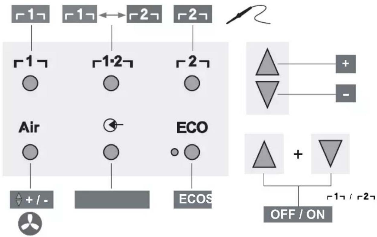
Quick Reference WR 2
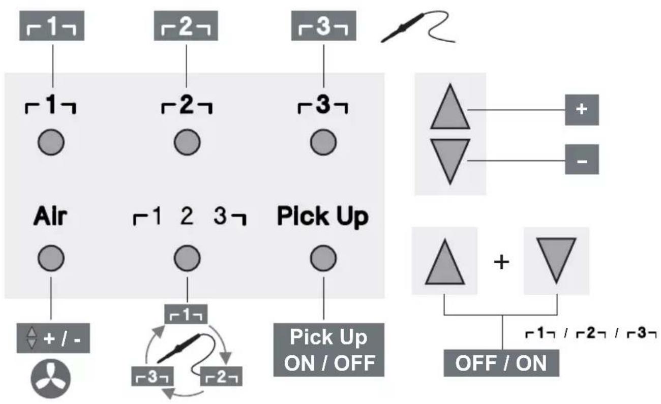
Quick Reference WR 3M
DE Menuaufruf
GB Open Menu
ES Acceso al Menu
FR Appel du menu
IT Richiama il menu
GB Starting up the device
GB Operating principle
ES Manejo
Thank you for the confidence you have shown in buying this device.
The device has been manufactured in accordance with the most rigorous quality standards which ensure that it operates perfectly.
Read these instructions and the accompanying safety information carefully before starting up the device and starting work with the device.
Keep these instructions in a place that is accessible to all users.
These instructions contain important information which will help you to start up, operate and service the device safely and correctly as well as to eliminate simple faults and malfunctions yourselves.
The device has been manufactured in accordance with state-of-the-art technology and acknowledged regulations concerning safety.
There is nevertheless the risk of personal injury and damage to property if you fail to observe the safety information set out in the accompanying booklet and the warnings given in these instructions.
Safety information
For safety reasons, children and youths under the age of 16, as well as persons who are not familiar with these operating instructions, may not use the device. Children should be supervised in order to ensure that they do not play with the tool. This device is not intended for use by persons (including children) with limited physical, sensory or mental aptitude, or by persons who lack knowledge or experience in handling the device.

Warning! Electrical shock
Connecting the control unit incorrectly poses a risk of injury due to electric shock and can damage the device.
Carefully read the attached safety information, the safety information accompanying these operating instructions as well as the operating instructions for your control unit before putting the control unit into operation and observe the safety precautions specified therein.
Only connect WELLER tools.
If the device is faulty, active electrical conductors may be bare or the PE conductor may not be functional.
Repairs must always be referred to a Weller-trained specialist.
If the electrical tool's power supply cord is damaged, it must be replaced with a specially prefabricated power supply cord available through the customer service organization.

Warning! Risk of burns
Risk of burns from the soldering tool while the control unit is operating. Tools may still be hot long after they have been switched off.
Always place the soldering tool in the safety rest while not in use.
Only connect the vacuum and hot air at the designated points.
Do not direct hot air soldering tools at people or inflammable objects.

Warning! Fire and explosion hazard!
Hot tools represent a fire hazard
Always place the soldering tool in the safety rest while not in use.
Do not direct hot air soldering tools at people or inflammable objects.
Keep explosive and flammable objects well away from the device.
Do not cover the device.

Warning! Danger of injury
The device or parts of the device may fall off during transportation.
Specified Conditions Of Use
Supply unit for WELLER soldering tools.
Use the repair station only for the purpose indicated in the operating instructions of soldering and desoldering under the conditions specified herein.

Flammable gases and liquids may not be extracted.
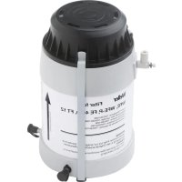
The device may only be used with correctly fitted and suitable filter cartridges.
Replace filter cartridges when full.
Only use the device indoors. Protect against moisture and direct sunlight.
Intended use of the soldering station/ desoldering station also includes the requirement that you
□ adhere to these instructions,
observe all other accompanying documents,
comply with national accident prevention guidelines applicable at the place of use.
The manufacturer will not be liable for unauthorized modifications to the device.
User groups
Due to differing degrees of risk and potential hazards, several work steps may only be performed by trained experts.
| Work step User groups | |
| Default soldering parameters Specialist personnel with technical training | |
| Replacing electrical replacement parts Electricians | |
| Default maintenance intervals Safety expert | |
| Operation Filter change | Non-specialists |
| Operation Filter change Replacing electrical replacement parts | Technical trainees under the guidance and supervision of a trained expert |
Starting up the device
Caution!
Please adhere to the operating instructions of the connected devices.
Put the tool into operation as described in the chapter „Placing into operation".

Check to see if the mains voltage matches the ratings on the nameplate.
Make sure the machine is switched off before plugging in.
After the device has been switched on, the microprocessor carries out a self-test in which all the segments are briefly in operation.
Soldering and desoldering
Carry out soldering work as directed in the operating instructions of your connected soldering tool.
Handling the soldering tips
Coat the selective and tinnable soldering tip with solder when heating it up for the first time. This removes oxide coatings which have formed during storage and impurities from the soldering tip.
Make sure that the soldering tip is well coated with solder during breaks between soldering work and prior to storage of the device.
Do not use aggressive fluxing agents.
Always make sure that the soldering tips are fitted properly.
Select as low a working temperature as possible.
Select the largest possible soldering tip shape for the application.
Rule of thumb: the soldering tip should be roughly as large as the soldering pad.
Coat the soldering tip well with solder to ensure
that there is efficient heat transfer between the soldering tip and the soldering area.
Prior to extended breaks between soldering work, switch off the soldering system or use the Weller function to reduce the temperature when the soldering equipment is not in use.
Coat the tip with solder prior to storage if you do not intend to use the soldering iron for an extended period of time.
Apply solder directly to the soldering area, not to the soldering tip.
Change the soldering tips using the designated tool.
Do not apply mechanical force to the soldering tip.
Notice
The control units have been adapted to hold a medium-sized soldering tip. Discrepancies may occur if the tip is changed or a different shaped tip is used.
Overload cut-out
To avoid overloading the station, power output is automatically reduced in the event of an overload.
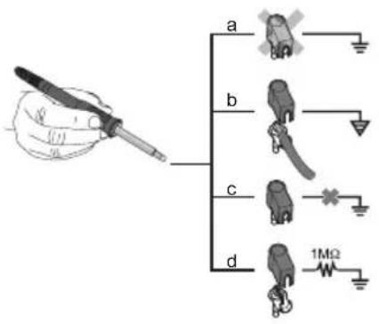
Equipotential bonding

Four variants are possible by connecting the 3.5mm jack socket differently:
| a Hard-grounded supplied | without plug. |
| b Equipotential bonding | with plug, equaliser at centre contact. |
| c Floating with plug | |
| d Soft-grounded with plug | and soldered resistor. Grounded through selected resistor. |
Carrying out a firmware update (WR 3M)
Notice
The control unit is equipped with a Mini USB port. To use the USB port, Weller provides software on so you can carry out a software update ("Firmware Updater") on your control unit.
Care and maintenance

Warning!
<Before doing any work on the machine, pull the plug out of the socket.

Warning!
Use original replacement parts only.

Warning! Risk of burns
Only replace solder tips when cold
Replace and clean suction nozzles only when hot and using the suitable tool
Only replace hot air nozzles using the suitable tool
Only clean or replace solder collection tubes when cold
Clean the operator panel, if dirty, using a suitable cleaning cloth.
Filter change
Check the filter regularly for contamination, and replace it if necessary.
Warning!
Failure to use a filter will cause irreparable damage to the vacuum pump.
Check before starting soldering whether a main filter is inserted.
Contaminated filters must be treated as special waste.
Dispose of replaced equipment parts, filters or old devices in accordance with the rules and regulations applicable in your country.
Wear suitable protective gear.
Standby Temp. (STANDBY)

Menu access


After activating the Setback function or after pushing the ECO button (WR 2), the temperature is automatically reduced to Standby temperature. The display flashes the actual temperature. <STANDBY appears on the display.
Setback time (SETBACK)

Menu access


If the soldering tool is not in use, the temperature is reduced to Standby temperature on expiration of the preset Setback time.
SETBACK appears on the display.
To exit Standby mode, push the ,UP / DOWN" buttons or ECO (WR 2).
Depending on the tool in use, the finger switch or the safety rest deactivates Standby mode.
| Option Description | |
| 0 min Deactivated (Default setting) | |
| ON After placing the soldering iron into the safety rest, the temperature is immediately reduced to standby level. | |
| 1-999 min | Setback time Individually adjustable |
AUTO OFF time (automatic switch-off time)

Menu access


If the soldering tool is not in use, the soldering tool is switched off on expiration of the AUTO-OFF time.
The actual temperature flashes on the display and serves as residual-heat indicator. "OFF" appears on the display. A flashing dash appears on the display below 50^ (122°F).
| Option Description | |
| 0 min Deactivated (Default setting) | |
| 1-999 min | AUTO-OFF time, can be set individually. |
Temperature-Offset (Offset)

Menu access


The actual soldering-tip temperature can be adapted by entering a temperature offset around ± 40^ ( ± 72^ ).
Temperature window (WINDOW)

Menu access


Starting from a set, locked temperature, it is possible to set a temperature window of ± 1 - 99^ ( ± 1 - 180^ ) using the WINDOW function. To use the WINDOW function, the repair station must be interlocked.
Temperature units (^ / ^)

Menu access


Option Description
| °C Celsius | |
| °F Fahrenheit |
Max. hot air duration (HAP On)

Menu access


The on-time of the hot air flow of the HAP 200 can be limited in increments of 1 to between 0 and 60 sec. The set time is then identical for all 3 channels.
The factory default is s ("OFF"), i.e. air flows only as long as the button on the hot air tool or the optional footswitch is pressed.
Option Description
OFF No duration defined(Default setting)
1-60 s Individually adjustable
Vacuum pre-feed (VAC On)

Menu access


In order to prevent the pump from starting prematurely or to ensure a defined soldering-joint preheating time, it is possible to set an ON delay.
Option Description
0 sec OFF: vacuum pre-feed function is OFF (Default setting)
1-9 sec ON: vacuum pre-feed time, individually
Vacuum run-on (VAC Off)

Menu access


To prevent the desoldering iron from becoming clogged, it is possible to set a vacuum run-on time. (factory setting 2 s)
Option Description
0 sec OFF: vacuum run-on function is OFF (Default setting)
1-5 sec ON: vacuum run-on time, individually adjustable
lock function
Menu access

After the lock has been activated, only the following buttons on the soldering station are enabled:
WR2:1,1·2,2,ECO,AIR
WR 3M: 1 , 2 , 3 , 1· 2· 3 ,PickUp,AIR
All other settings are disabled until the repair station is unlocked again.
Notice
If you want only one temperature value to be selectable, the control keys fixed temperature keys) must be set to the same temperature value.
Locking the soldering station
Select menu option. "OFF" appears on the display. The key symbol is flashing.
Set the desired three-digit locking code (between 001 and 999) using the UP / DOWN buttons.
WR 2: Press button 2 for 5 seconds.
WR 3M: Press button 3 for 5 seconds.
The code is stored.


The key symbol is displayed.
Unlocking the soldering station
- Select menu option. "ON" appears on the display.
- Set the three-digit locking code using the UP / DOWN buttons.
3.WR2:Pressbutton 2 . WR3M:Press button 3 - The station is now unlocked. The display switches to the main menu.
Forgotten code?
Please contact our Customer Service: technical-service@weller-tools.com
Pressure gauge threshold (LEVEL)

Menu access

This function can be used to define the maintenance interval of the desoldering tool. This is done by setting the value in mbar at which the electric pressure gauge issues a warning signal when the intake system is contaminated (LED of the vacuum pump switches from green to red). The set value is dependent on the suction nozzles used.
Adjustable -400 mbar to -800 mbar
factory setting -600 mbar
- The system (tips and filter) must be free.
- Select the menu item „Pressure gauge threshold" in the menu.
- Set the "Pressure gauge threshold" pressure value with the UP or DOWN button. The status LED switches back and forth between red and green. Use the UP button to increase vacuum by 50 to 80 mbar, then pinch the vacuum tube and check whether the LED switches from green to red.
Station code (Remote ID)

Menu access

WR 3M
A station code (Remote ID) can be assigned to each station, allowing the station to be clearly identified via the USB port.
Option Description
0-999 Individually adjustable
Calibration (Factory Calibration Check FCC)

Menu access

You can use the FCC function to check the temperature precision of the repair station and even out possible deviations. For this purpose, the soldering-tip temperature must be measured with an external temperature meter and a temperature measuring tip assigned to the soldering tool. The corresponding channel must be selected prior to calibration.
- Insert the temperature sensor (0.5mm) of the external temperature meter into the temperature measuring tip.
- Select the menu item FCC in Menu 2.
- a) Press the DOWN button. -> Calibration point 100^ / 210^ is selected. b) Press the UP button. -> Calibration point 450 ^ C / 840^ is selected.
The soldering tip is now heated up. The control indicator flashes as soon as the temperature is constant.
- Compare the temperatures indicated by the meter with the readings on the display.
- WR 2: Push the 1· 2 (Set) button to confirm the adjusted value.
WR 3M: Push the 1· 23 (Set) button to confirm the adjusted value.
The temperature deviation is now reset to 0. Calibration at 100^ / 210^ / 450^ / 840^ is now complete.
- Use the UP or DOWN button to set the difference between the value indicated on the external meter and the value indicated on the repair station. Maximum possible temperature adjustment ± 40^(± 70^)
WR 2: Push button 2 to exit the menu option (EXIT).
WR 3M: Push button 3 to exit the menu option (EXIT).
- WR 2: Exit Menu 2 with button [2].
WR 3M: Exit Menu 3 with button 2 .
Resetting calibration to factory settings
-
Select the menu item FCC in Menu 2.
-
WR 2: Press and hold down button 2
WR 3M: Press and hold down button 3
- Then press the UP and DOWN buttons simultaneously. "FSE" (Factory Setting Enabled) appears on the display.
The repair station is now reset to the factory calibration.
Activation / Deactivating the special button (SP Button)

Menu access -2-
WR2
After activating the special button, it can be used as a shortcut back to Menu 1. The function previously selected is saved when the menu is exited with the special button.
Option Description
OFF Deactivated(Default setting)
ON Special button activated
Activation / Deactivating the ECO button (ECO)

Menu access -2-
WR2
After activating the ECO button, it can be used to set all channels to Standby mode. The green LED lights up and the channels are set to the set standby temperature. If a safety rest is in use, the function is reset when the tool is removed from the holder.
Option Description
OFF Deactivated(Default setting)
ON ECO button activated
Button lock HAP 200 (HAP LOC)

Menu access -2-
WR 3M
This function can be used to adjust the factory button presets of the WXAHP tool.
The HAP 200 is switched on the first time the button is pressed and switched off the next time the button is pressed.
Option Description
OFF Deactivated(Default setting)
ON HAP LOC activated
Perform.Mode Menu access -2-


The function determines the heating characteristics of the soldering tool to achieve the set tool temperature.
Option Description
LO Slow heating
HI rapid heating
Resetting to factory settings (FSE)
Select the menu option FSE in menu 1.
WR 2:Press and hold down button 2
1Open special functions menu ,1" (push UP & DOWN buttons simultaneously for 2sec.)
2. Press and hold down button 2
3. Then press the UP and DOWN buttons simultaneously. FSE appears on the display. (Factory Setting Enabled).
The repair station is now reset to the factory settings.
Reset the calibration values to the factory settings
- Open special functions menu,2" (push UP & DOWN buttons simultaneously for 4sec.)
- Select menu option ,FCC".
- Press and hold down button 2
- Then press the UP and DOWN buttons simultaneously. FSE appears on the display. (Factory Setting Enabled).
The repair station is now reset to the factory settings.
WR 3M: Press and hold down button 3
- Open special functions menu, 1" (push UP & DOWN buttons simultaneously for 2sec.)
- Push button 3 and hold it down.
- Then press the UP and DOWN buttons simultaneously. FSE appears on the display. (Factory Setting Enabled).
The repair station is now reset to the factory settings.
Reset the calibration values to the factory settings
- Open special functions menu,2" (push UP & DOWN buttons simultaneously for 4sec.)
- Select menu option "FCC".
- Push button 3 and hold it down.
- Then press the UP and DOWN buttons simultaneously. FSE appears on the display. (Factory Setting Enabled).
The repair station is now reset to the factory settings.
| Repair station WR 3M WR 2 | ||
| Dimensions L x W x H (mm) | 273 x 235 x 102 | |
| Dimensions L x W x H (Inch) | 10.75 x 9.25 x 4.02 | |
| Mains supply voltage 230 V ~ 50/60 | Hz | 240/120 V ~ 50/60 Hz | |
| 120 V ~ 60 Hz | 100V ~ 50/60 Hz | ||
| Power consumption 400 W 300 W | ||
| Safety class I, antistatic housing | III, Soldering tool | |
| Fuse Overcurrent release 230 V; 2,0 A | 120 V; 4,0 A | 1,6 A |
| Temperature (Tool dependent) °C | 50 - 450 (550) | |
| Temperature (Tool dependent) °F | 150 - 850 (999) | |
| Temperature accuracy °C | ± 9 | |
| Temperature accuracy °F | ± 17 | |
| Temperature accuracy Hot air °C ± 30 | ||
| Temperature accuracy Hot air °F ± 54 | ||
| Temperature stability °C | ± 2 | |
| Temperature stability °F | ± 4 | |
| Equipotential bonding Via 3.5 mm paw | socket on back of unit (delivery form: hard grounded without jack plug) | |
| Display LCD | ||
| USB port The control unit comes with a front-side USB port for installing firmware updates, configuration and monitoring. | - | |
| Pump (Intermittent mode (30/30) s) Max. | vacuum 0,7 bar | |
| Maximum quantity supplied 18 l/min | ||
| Max. hot air 15 l/min | ||
| Additional vacuum pump Max. vacuum | 0,5 bar | |
| Maximum quantity supplied 1,7 l/min | ||
Error messages and error clearance
| Message/symptom Possible cause | Use Remedial measures | |
| Display: „- - - | ☐ Tool has not been detected ☐ Tool defective | Check connection of tool to device ☐ Check connected tool |
| No display function (display OFF) | ☐ No mains supply voltage | Turn on mains power switch ☐ Check mains supply voltage ☐ Check device fuse |
| No vacuum at desoldering tool | ☐ Vakuum nicht angeschlossen ☐ Desoldering nozzle clogged ☐ Pump faulty | Connect vacuum hose to vacuum connection ☐ Service desoldering nozzle using cleaning tool |
| Insufficient vacuum at desolde-ring tool | ☐ Filter cartridge on desoldering tool full ☐ Main filter full | Change filter cartridge on desoldering tool full ☐ Change the main filter element on the soldering station |
| Hot air tool has no air | ☐ Air hose not connected ☐ Main filter full | Connect or check air hose ☐ Change the main filter element on the soldering station |
Z
Symbols

Caution!

Read the operating instructions!


Before performing work of any kind on the unit, always disconnect the power plug from the socket.

ESD-compatible design and ESD-compatible workstation
Equipotential bonding

CE mark of conformity

British Conformity Mark

Fuse

Safety transformer

Soldering
Warranty
Claims by the buyer for physical defects are timebarred after a period of one year from delivery to the buyer. This does not apply to claims by the buyer for indemnification in accordance with 478, 479 BGB (German Federal Law Gazette).
We shall only be liable for claims arising from a warranty furnished by us if the quality or durability warranty has been furnished by use in writing and using the term "Warranty".

Desoldering

Hot air

Disposal
Waste light sources have to be removed from equipment. Check with your local authority or retailer for recycling advice and collection point. According to local regulations retailers may have an obligation to take back waste electrical and electronic equipment free of charge. Your contribution to re-use and recycling of waste electrical and electronic equipment helps to reduce the demand of raw materials. Waste electrical and electronic equipment contain valuable, recyclable materials, which can adversely impact the environment and the human health, if not disposed of in an environmentally compatible manner. Delete personal data from waste equipment, if any. Contaminated filters must be treated as special waste. Dispose of replaced equipment parts, filters or old devices in accordance with the rules and regulations applicable in your country.
The warranty shall be void if damage is due to improper use and if the device has been tampered with by unauthorized persons.
Subject to technical alterations and amendments.
For more information please visit www.weller-tools.com.
Coupure de surcharge
Calibrage (Factory Calibration Check FCC)
Calibrazione (Factory Calibration Check FCC)
Calibragem (Factory Calibration Check FCC)
Stationsidentificatie (Remote ID)

Menu-oproep


WR 3M
Varning! Risk for brännskador
Varning! Risk for brännskador
Stationsidentitet (Remote ID)

Menyanrop


WR 3M
WR 3M: Pida nappainta 3 painettuna.
WR 3M: Pida nappainta 3 painettuna.
Setback suresi (SETBACK)

Menu arama -1
Fabrika ayari s ("OFF") biçimindedir, yani sıçak hava pistonundaki tuşa veya isteğe®,®,®,®,®,®,®,®,®,®,®,®,®,®,®,®,®,®,®,®,®,®,®,®,®,®,®,®,®,®,®,®,®,®,®,®,®,®,®,®,®,®,®,®,®,®,®,®,®,®,®,®,®,®,®,®,®,®,®,®,®,®,®,®,®,®,®,®,®,®,®,®,®,®,®,®,®,®,®,®,®,®,®,®,®,®,®,®,®,®,®,®,®,®,®,®,®,®,®,®,®. Sokulur.
Kalibrasyon (Factory Calibration Check FCC)

Menu arama

Bridinajums! Traumu risks
Transportesanas laikierice var apgazties vai ar var nokrist detalias.
Kalibreevana (Factory Calibration Check FCC)
Ar FCC fungciju var parbaudit remontiekartas temperaturas precizitate un noverst iespejamas novirzes. Tadel lodgalvas temperatura jamera ar areju temperaturas merisanas iceri un lodamuram pievienoto temperaturas mergalvu. Pirms kalibresanas jaizvelas atbilstošais kanals.
- levietojiet arejas temperaturas merisanas ierices devej (0,5mm) temperaturas merijumusmaile.
-
- izvēnlē atlaisiet FCC.
- a) Nospiediet taustiun "DOWN". -> Tiek izveletskalibresanas punkts 100 ^ C / 210^ b) Nospiediet taustiun "UP". -> Tiek izveletskalibresanas punkts 450 ^ C / 840^ Tagad lodesanas uzgalis tiek uzkarsets.Reguleşanas kontrole sak mirgot, tikliztemperatura ir nemainiga.
- Salidzinet merierces temperaturas radijumu ar radijumu displeja.
5.WR2:Lai apstiprinatu korigeto vertibu, nospiediet taustiu 1· 2 (Set"). WR 3M: Lai apstiprinatu korigeto vertibu, nospiediet taustiu 1· 23 (Set). Temperaturas novirze ir atiestatita uz 0. Kalibresana 100^ / 210^ / 450^ / 840^ temperatura tagad ir pabeigta.
Izvelnes izsauksana -2-
- Ar taustiñu „UP" vai „DOWN" iestatiet remontiekártā ārejas mérierices un stacijas uzradito temperatu ru starpibu. Maksimalais iespejamais temperaturas izlidzinajums ±40 °C (±70 °F).
WR 2: Nospiediet taustinu 2, lai izietu no izvēlnes ("EXIT").
WR 3M: Nospiediet taustinu 3, lai izietu n izvēlnes ("EXIT").
7.WR2:Ar taustiu 2 izejiet no 2.izvvelnes. WR3M:Ar taustiu 3 izejiet no 2.izvvelnes.
Atiestatit kalibresanu uz rupnicas iestatijumiem
1.2. izvēnlē atlasiet FCC.
2.WR 2: Turiet nospiestu tausti 一 2 7. WR3M: Turiet nospiestu tausti 一 3 7.
3. Pec tam vienlaicigi nospiediet taustinus "UP" un "DOWN". Displeja paradas "FSE" ("Factory Setting Enabled"). Tagad remontiekartas kalibresana ir atiestatita uz rupnicas iestatijumiem.

WR 3M: Paspauskite mygtuka 3
- Dabar stotelé atrakinta. Ekrane parodomas pagrindinis menui.
Pamiršote koda?
Kreipkites j musu klieny aptarnavimo tarnyba: technical-service@weller-tools.com.

Manometro slenkstis (LEVEL)
CbbpkeTe cAmO nHCTpyMeHTN WELLER.
Pn depeKeTeH ypeE b3MOxHO aKTNBn IpOBOHnCi Da ca OROeHN nJN 3aunTHnT npOBODnK Da He pa6OTn.
PemontTe Tp6Ba da ce n3BbpuBaT ot o6yehn ot Weller Iua.
Ako e nobpeDeH cbEHHHTeHnHa npOBoHNK Ha eNeKTpUeCKn HA HCTpyMeHT, TO ToT pr6Ba Da ce cMeHcBc CneuaH NoIgrotBeH cbEHHTeHe npOBoHNK, KOTo MOKe Da ce noJyH ot cepBn3HaTa opraHn3aun.

PpeynpeXeHne! Pnck OT n3rapnna
Ipn pa6ota Ha anapata 3a ynpabJIeHne HMa onaCHOCT OT n3rapHe NO NOJIHHn IHcTpymEHT. INcTpymEHTnte MORaT Bce Oue da 6bDaT ropeuN dJbIro cJeD KaTo Te He ca 6NJN N3KJIIOUeHn.
Ako He n3noJ3BaTe noJHHnHn HnCTpyMeHT, BnHaTn rO cIaraiTe B npedna3HaTa NoCTaBAka.
C8bpxKeTcAmoBaKyMaHropeuBb3dyxBOnpeJeHeHTe NyHKTOBe.
He hacouBaIe ropeunBb3dUx INcTpymEnTn 3anOraBe npn Xopa nn 3anaNIMnpedMeTu.

PpeynpexdHne!OrbHn onachocT oeknno3na!
IopeuHnHcTpymEnT npEcdTabJbBaT onaCHOCT OT noXap
Ako He n3noJIbATE NOJHnI INCTpyMeT, BnHaI rO cIaIaTe B npedna3HaTa NoDCTaBAka.
He hacouBaTe ropeunBb3dyx INHCTpyMeHTn 3anOBaHe npxopa nn 3anaJIMn PpeDMeTn.
I DpbjTe B3pNBn n 3anaJIMn npedMeTn daJece OT yCTPONCBOTO.
He nokpmbaHcHa yctpoNCTBOTo.

PpeynpekdeHne! Mma onaCHOCT OT HapaHbAhe
PtpaHcnpT ypeBt nnn qactn ot Hero Moat da naadhat doJy.
I3noJI3BaHe no IpeIHa3HaueHne
IocTabka eHnua 3a WELLER 3anOBaHe INHCTpyMeHTN.
I3noJ3BaIte peMOHT cTaHcIgCaMo 3a ueJIta, nocOueHa B pBkoBOdCTBOTO 3a ekCnloaTaun Ha 3anOraBaHe I pa3NoRAhe CbflacHO ycNoBnraTa, nocOueHr TyK.

3anaJIMnra3OBe n TeUHOCTN, KONTO He MoRat da 6bDat N3BNeueHn.
YcTPOINCTBOTO MOKe Da Ce N3NOJ3Ba cAmO C npaBnHO MOHTnpaHn I NOxODAUNI FNITbPHN KAcETN.
CmeHeTeΦnTTbPHN KaceTN, KOraTo nblHn.
N3PONJ3BaIte yCTPOINCTBOTO cMo B 3aKpNTn NOMeueHn. Da ce Na3n OT Bnara n npraKa CJIbHuEBA CBETJInHa.
I3noJI3BaHHeTo NO npeHa3Na3HuE Hne BkJIIOUyBa I
Bue da cna3BaTe TOBa pkoBOcTBO,
CnataBaIte BCNUKIN DonbHInTeHN HcBnpoBOIDNTeHN DOKyMeHTaUIN.
Bne da cna3BaTe HaunohnHnTe npabnla 3a Texnka Ha 6e30nacHOCT Ha MrcTOTO Ha pa6ota.
Pon3BOJTeJIr He Noema OTROBOpHcT 3a HanpaBeHN CBOEBoHn N3MeHeHn Ha ypeHa.
NoTpe6bTeJcKn rpynn
Iopapn pa3nnH roJemnte pncOBe n noTeuuaHn onachocTH HAKON pa6oTHn onepaun MoarT da 6bDat N3BpUbaHc moO T KBAInΦnupaH n o6yeh nepcohan.
Pa6oTha onepaunr PoTpe6nteIckn rpynn
AkyaIIN3npaHe Ha qnpMeHnra coqTyep (WR 3M)
YKa3aHue
Anapamb m 3a ynpaeeneHue UMa eouh MuHu uHmeppeuc USB. 3a u3non3eaHem o uHmeppeuca USB Ha Bawe pa3noJoxHe cbc coqmyep Ha Weller, c KoUmo moXeme da HanpaBume akmyan3upahe Ha coqmyepa (Dupmen akmyanuzamop) Ha BaWua anapam 3a ynpaeeneHue.
06cnyxbaHe n noDdbpxkaHe

PpeynpekdeHne!
<πpeδ 3aŋoʊbahe ha paδomu no ypeδa u3eademe uekepa om KOhmaKma.

PpeynpekdeHne!
I3non38aume camo opuzuHaHnpe3epHu yacmu Ha WELLER.

PpeynpeXeHne! Pnck ot n3rapaHn
Camo 3aMeHn cBBETn CnoIka, KOrato e CTydeH
3amHaNCHNTIIO3N CMyKaTeJIHn cAmoKorato ropeuO n NOMOHTa Ha NOxOJaU INCTpyMeHT
Camo 3aMeHr OpeuBb3dUshn H03N, KaTO CE n3No13Ba NOxOJaH INHcTpymENT
Camo nouCTn Hnn 3aMeHn Tpb6n 3a cb6npaHe Ha cnoiKa, KoraTo e CTydeH
Pn 3aMbpcaBe noocTe neyta 3a npabHe nC noXoJa Kbpna 3a noocTbaHe.
CmHa HaΦnTbpa
PpOBepaTe peoBHO 3ambpcBaHTo Ha cnIbpa 3a BaKyyMa n npn Hxka ro CMeHeTe.
PpeynpekdeHne!
Pn pa6ota 6e3 pntbpaKayyMaTa nomna ce pa3pywaBa.
IpeN3anoBaHeHaCnoBaHe npOBepe TaHIMa CNOKeH rnaBeH qnTbp!
3ambpceHume pfummp6ba da ce
pa3aIexdAm kamo cneuaanu omnaDbu.
Omcpanhaue mCmeHume yacmu
Ha ypeu, pfunmu unu cmapu ypeu e
cbomeemcmeue c 3akohodamencmeomo Ha
Bawama cmpaHa.
Ja ce Hocu nooXoAzo 3aumHo o6opyeaehe.
Standby Temnepaotypa (STANDBY)

MeHIO 3a DoCTbI -1-
Cne akTbBpAHe Ha cyHKcIyTa Setback nI npn 3aJeIcTBaHc Ha ECO-6yToHa (WR 2) TeMnepaTypaTa aBtOMaTHUHO ce noHIXkAbDo HnBO Standby. DeIcTBuTEJIHata TempepaTypa ce noka3Ba Mrra. <Ha dncnpee ce noRBA „STANDBY".
Bpeme Setback (SETBACK)

MeHIO 3a IOCTbI -1-
Ako He n3noJ3BaTe NOJIHHa INHCTpyMeHT, Tempepatpata CneI n3TnHaHe Ha 3aJaDeHOTo 3a Setback BpeMe ce noHxKaba Do Tempepatypa 3a peKIM Standby.
Ha nucnpe ce noyBa, SETBACK".
HaTnckaHe Ha 6yToHa ,UP /DOWN" uN ECO (WR 2) 3abbpwBa cbctOraHneTo Standby.
B 3aBnCmOCT OT INHCTpyMeHTa 6yToHbT HnnpBeKIIIOUBAuTa IoNCTaBka DeakTNBupatpeXIma Ha Standby.
| Опеля Оп�саниne | |
| 0 min Deак | Тивиране (заворская) настоюка) |
| ON C рөв | Клочваца түдүстовka след слагане на погиника Төмөратура Вedingara ce погиника до реким Standby. |
| 1-999 min | Вөрeme Setback Иndиевдуално perулирүүм |
AUTO OFF Bpeme (Bpemeto 3a aBTOMaTnUHO n3KJIIOUBAHe)

MeHIO 3a DoCTbI -1-
Ako He n3noJ3BaTe NOJHHnI INHCTpyMeHT ToI Ce n3KJIIOvBa CneI n3TInuHaHe Ha BpeMeTo 3a AUTOOFF.
ДeиCTBNTeJIHаTe TempepaTpa Mra n cIyKn 3a ИндиKaця Ha ocTaTbUHaTа TempepaTpa. Ha ДиСплЯ ce noяВЯBa „OFF". ПоJ 50 °C (122 °F) ce noяВЯBa edHa Miraanza.YeptTuKa.
WR 3M:HaTnchete6yToHa 3
4.Cera ctaHcIyTa e pa36IOKIPAHa. INHdkaIcNroTnBa B IJIaBHOTO MeHIO.
3a6paenu cme koda?
MoncBpKemecnawamacepuHa cnjx6a:
technical-cepeu3eH@Weller-tools.com

Ipar MaHOMeTbp (LEVEL)

MeHIO3aIOCTbI


Ta3nФункиЯ може да ce n3noJ3Ba 3a onpeДeJIЯHe Ha INTEPBAJaHa nOДрьЖka Ha INHCTpyMeHTa pa3noJBAHe.ToBa ce OcbIeCTBra Ype3 onpeДeJIЯHe Ha cToHocTtA B MnIbapa npi KOrTO rAbapIT eNeKTPuYeCKn HaNrAhe N3daBa npeDynpdTeJIeN CnHAn, Korato BCMyKaTeJHaTAtcNCTema e 3aMbpcHa (LED Ha npeBKnIOUba Bakyum NOMna OT 3eJIeHO Do uepBeHo). 3aJaDeHATA cToHOCt e 3aBNCmOT dIO3nTe Ha cMyKaTeJHInTe N3noJ3BaHn.
perynipyem -400 mbar 3a -800 mbar
fa6pnHnHa HacTpoiKa -600 mbar
- CnCTemata (cBbTeN nФntTp) Tp8Ba Da 6bDe cBo6oJeH.
2.Изберето.Toka,пpara MaHOMeTbP"MeHIO B MEHHTO. - 3aДaIte „npar MaHOMeTbP" CToHOCCTTa Ha HaIraHeTO c UP nnn DOWN 6yToHa. ИнДИКaTOPbT 3a CbCTOaHNeTO npeBKnIOuBa HAnpei N Ha3aI MekJy ЧерBEHo I 3eJIeHO. ИЗПОЗВaIte 6yToHa UP da ce YBeIuH BAKyyM OT 50 Do 80 MnIn6apa, cIeI TOBa 3axBaHete BAkyuMHaTa Tpb6a I npOBepTe dani LED npeBKnIOUBy O t 3eJIeHO Do ChpBeHo.
IdENTnФнkaцna Ha cTaHczra (Remote ID)

MeHIO3aIOCTbI


WR 3M
3a BCsKa CtAnCuJa MoKeTe Da ce OnpeDen EHa HNeHTnФKauN Ha CtAnCuTaN (Remote ID), 3a MOKe TReENo3HaUHa Da ce NDeHTnФNupa OT USB-INTeppeiCa.
onun Onncanne
0-999 INHINBnDyaanHo peryInpyeM
Kanibpnpahe (Factory Calibration Check FCC)

MeHIO3aIOCTbI


C cyHKzraTa FCC Bne moXeTe da npOBepnTe ToUHOCTTa Ha TEMpepatypata Ha peMOHTHaT aTaHcN I KOMHeHCupate eBENTaHnITE OTKNOHeHna.3a Ta3n cen e Tp6Ba Da ce N3Mepu Tempepatypata Ha NaKpaHnKa Ha N0AHHka C eINH BbHWeH ypeD 3a N3MepBaHe Ha TEMpepatypata N C eINH CbOTBeTeH 3a N0AHHn HnCTpyMeHT NaKpaHnK 3a N3MepBaHe Ha TEMpepatypata. PpeDn 3anoYBaHe Ha KaJIb6pnpaHe Tp6Ba Da ce N3Bepe CbOTBeTHnKaHaI.
1.ВkapaTe TepMoUyBCTBNTeHnIeJeMeHT (0,5 MM)Ha BbHsHnIypeI3a I3MepBaHe Ha TempePaTypaTb HApKaHnka 3a I3MepBaHe Ha TempePaTypaTa.
2.ИзберетьMeHIO2ToUkaTaHa MeHIOTo FCC.
3. a) HaTnchTe 6yToHa DOWN . -> N3bnpa ce KaIb6pObBcHHaTa TOnka 100 °C / 210 °F. b) HaTnchTe 6yToHa UP . -> N3bnpa ce KaIb6pObBcHHaTa TOnka 450 °C / 840 °F. Cera HApaHnKbT Ha NoJHnKa ce HarpaBa. KoHTpOblT Ha perynpaHeTo 3anoYBa da Mrra npi DoCTnRaHe Ha NoCToHnHa TeMnepaTypa.
4. CpaBHeTe Ioka3BaHaTa TeMnepaTypa Ha n3MePbATEJIHnIypeI C INHnKaunraTa Ha nnCnIeJ.
5.WR2:HaTnchTe6yToHa1-2(Set),3a da ce nOTBbpNn npOMEHeHaTa cToHocT.
WR 3M:HaTnchTe6yToHa1-2-3(Set),3a da ce nOTBbpDn npomeHeHata cToHocT. Cera TempepatypHOTo OTKIOHeHne e 3aDaJeHo Ha0.Cera kaIb6pnpaHeto npn 100^ / 210^ 450^ / 840^ e npnkIoueHo.
6.C 6yToHa UP nIN DOWN BbBeTe B peMOHTHaTcTaHnPa3Nkata MExdy NOKa3BaHaTAt O T bHnHnNn3MepBaTeIeH ypeI NOT CTaHnraCTOnHOCT. MakcImaHNO Bb3MoXHTo TemnepaTyphO cbrNaCyBaHe e ± 40^ (± 70^)
WR 2: HatncheTe 6yToHa 2 ,3a da n3Je3eTe OT Toykata Ha MeHTo (EXIT).
WR 3M: HatncheTe 6yToHa 37, 3a da n3JIe3eTe OT ToUKKaTa Ha MeHIOTO (EXIT).
7.WR2:IV3nE3TeOTMeHHO2c6yToHa[2].
WR 3M: IV3ne3Te OT MeHIO 3 C 6yToHa 2
Bb3TaHOBBaHe Ha 3aBOdCKOTO KaJIb6pnpaHe
1.И36epeteBMeHIO2TOUkaTaHaMeHIOToFCC
2.WR2:HaTnCHHeu 3aApbXkTe6yToHa[2]
WR 3M:HaTnchHeTe n 3aApbXTe 6yToHa 3
- Cnej TOBa HaTnCHeTe eHOBpeMeHHo 6yToHIne UP n DOWN.Ha dncnpe ce noBraFSE" (Factory Setting Enabled). Cera peMOHTHaTa cTAnu e OTHOBCbC 3aBOdCKOTO KaINbPupaHe.
AektBupaHe / DeaekTbUpaHe Ha cneuaHnna 6yToH (SP Button) MeHIO 3a DocTbI
WR2
Cne akTnBupaH He cneuHaNna 6yToH C Hero BHe moKte 6bp3o Da OTndTe B MeHIO 1. Pn H3JIn3aHe OT MeHIO TO NocNeHaTa N36paHa fYHKcIe Ce 3anametra BcC cneuaJIHnA 6yToH.
onunnncnne
OFF DeaktnBupaHe (3aBoDcKa HacTpoika)
ON CneuaneH 6yToH aKTHBnpaH
AektubipaHe / DeakTbipaHe Ha 6yToHa ECO (ECO)

MeHIO 3a IOCTbI -2-
WR2
CneIakTNBnpaHeHa6yToHaECOcHeroMOKeTe Da3aAdTepeXIM3arotOBHOCT3a pa60Ta (Standby)3aBCnKnKaHAn.CBeTn3eJeHaTa LEDi KaHApTe ce peryNipat Ha 3aJaDeHaTa 3a Standby TemnepaTypa.Ppn n3nonBaHe Ha npebKnIOuBaUaNoCTabKaФyHKunraTa CeOTMeHr
PnN 3BaXdaHe Ha HhCtpymeHTa OT NOCTaBkata.
onunqnncanhe
TpaHcDopMaTop 3a 6e3oNaCHOCT

3aNoBaHe

pa3nBaHe

IopeuBb3dyx

OTctpaHbAne kato otnaBk
OtnaBcHTeOT eNEKTPuecko n
eNEKTPOHNOOBpyDbaHe Tp86Ba
da ce cb6npat N3XBbPnT
pa3dEHHo. PpeNn3XbPnHETO
OTCTPAHBAITE JAMnTE OT ypeHTe.
INΦOPMnPaIte CEOT MeCTHtete
Clyk6n INn OT CBOr CNEuHaJn3nPAH
TbProBEU OTHOCHOIpMNTe 3a
peuNKnIpaHE N MeCTATA 3a cb6nPAHe
ha OTnaDbu. B 3aBNCIMoCT OT
MeCTHtTe pa3nope6n, TbproBcHTe
Ha Dpe6Ho MOraT ca 3aDbLnKeHN
da npneMat 6e3PiNaTHO BpHaTtete
OBpaTHO OTNaDbuN OT eNEKTPnuCeCKo N
eNEKTPoHNOOBpyDbaHe. DaIte CBOr
PiHoc 3a HamaJIraBaHTo Ha HyxNDte
OT cyPOBHN Upe3 NOBTOPhata
yNoTpe6a N peuNKnIpaHTo Ha
BaHtete OTNaDbuN OT eNEKTPnuCeCKo
N eNEKTPoHNOOBpyDbaHe.
OTNaDbuNTE OT eNEKTPnuCeCKo N
eNEKTPoHNOOBpyDbaHe CbDbpxKaT
ZEHn peuNKnIpaUe Ce MaTePuaH,
KoHTO MORAT DA NOBNIyAR
OTpuCaTeHNO Ha OKJHATA CpeDa N HA
BaWeTo 3dpabe, Ako He ce n3XBpNt
no ekONorocBo6pa3eH NaHH. PpeDu
n3XBbPnHETO KATO OTNaDbK n3TPnITe
OT BaWn ynotpe6RaBn YpeD
EBeHTyaHNO HaNNHtE B Hero NUnHn
daHHN.
3ambpceHNTe cHnTPn Tp6Ba da ce pa3rJekDaT KATO CneuaJHn OTnaDbu. OtctpaHraBaHTe cmHeHNTe yactn Ha ypeDn, HnTPn nn CTapn ypeDn BCbOTBeTCTBnE C 3aKoHOdaTeJNCTBOTo Ha Baata cTpHa.
TapaHcua
IpeTeHcInTe KbM KaueCTBOTO Ha KyNyBaayu HMaT DaBHocT eHa rOyHa cJeD daTaTa Ha DoCTaKa npu KyNyBaaya. Toba He Baxn 3a perpeChn IpeTeHcIn Ha KyNyBaaya no 478,479K.
Hne Hocim OTROBOPHOCT NO DaJeHaTa OT Hac rapaHcna cAmO, KOraTO rapaHcnaTAta 3a CBOIcTBaTa nn 3a cPoka Ha roDHOCT e daHeHa OT Hac B INCMeH BVd N KaTO pN TOBa e n3NoJ3BaHo IOHrTNeTo ,rapaHcna".
TapaHnraTa r6n cna npn HnpaBnHo
H3noJ3BaHe n KOraTo HeKBaInΦnUpaHn Lnua ca
HaPaBnMaHnPyNau.
IpaBTo 3a npaBeHe Ha TexHnueckn n3MeHnna octaba 3ana3eHo!
Moi nHOpmuaTe ce Ha aDpec www.weller-tools.com.
Calibrare (Factory Calibration Check FCC)
Cu functia FCC puteti verifica precizia temperaturi statei de reparati si puteti compensa eventualele abateri. In acest scop, temperaturea varfului de lipit trebuie masurata cu un aparat extern de masurare a temperaturi si cu un varf de masurare a temperaturi associat sculei de lipit. Inainte de calibrare trebuie selectat canalul corespunzator.
- Introduciş senzorul de temperatura (0,5 mm) al aparatului extern de masurare a temperaturi in vârful de masurare a temperaturi.
- In meniul 2, selectati punctul din menui FCC.
- a) Apasati tasta DOWN. -> Va fi selectat punctul de calibrare 100^ / 210^ . b) Apasati tasta UP. -> Va fi selectat punctul de calibrare 450^ / 840^ .
BHHMaHHe! Ydap TokOM
B pe3yIbTaTe HnpaBnIbHoro NoDcoEduHeHn 6NoKa ynpaBneHn BO3HnKaet onacHOCTb nopaxeHn 3NeKtpnueckm TOKOM n NobpeXdHn ycTpoiCTBa.
BHNMaTeIbHO npOHTaIe TnpUraAemIe yka3AHnI NO texHnke 6e3OnaCHOCTN, yka3AHnI NO texHnke 6e3OnaCHOCTN, coDePkaIuecB DaHHOM pyKoBOdCTBe NO 3KcnNyatauIN, a TaKKe B pyKoBOdCTBe NO 3KcnNyatauIN BaWero 6Loka YnpaBHeHnI NpeD BBOOM B 3KcnNyatauIN H co6JIouaIte CoepKaIuecR B HIX Mepbl PpeIOctOpoxHOCTN.
I IopocoeHnHrTe TOnbKO INcTpymEnTbI WELLER.
B HenncpabHom yctpoicBe oroJIeHHbIe npOBA mOry T haoOnTbcra NOd HapJxHHeM nn 3aunTHbIe npOBA mOry T He BbINOJnHrT bCBOO fYHKcHIO.
PemOHThbI pa60tbI DoJXHbI BblNoJHrTb CneuaJIncTbI, npOweJIne oByeHne B KOMNaHnWeller.
Ipn noBpeXdeHn cTeBOrO Ka6eNa OH nOpIeXnT 3aMeHe Ha CneuaJIbHO nOIOrTOBneHHbIcTeBOI Ka6eNb, KOTOpBI MOKHO NOnyUHT B OprAHn3aUN, OCyUeCTBnIouSeiNoCnEIpOdaJxHoe o6CnyXnBaHne.

BHHMaHHe! OnaChocTb oxKora
Bo Bpempa60b6noka ynpablenen cyuectByeT onachoctb oxorOB ha naJIbHOM nHctpymte. NocJe OTKIOUeHn INHcTpymeHTbI MOryT B TeueHne DInTeJbHoro BpemeHn OCTaBaTbC ropqHmN.
Ecn nnaHbHn HnctpyMeHT He nCnoB3yETc, Bcerda xpaHInTe ero 6e3OnaCHOM MeCTe.
I OIOBODHTe BakyM I ropAHy N BO3dyx TOJbKO K npEHa3HaYeHHbIM dJIr 3TOrO pa3BeMaM.
He HanpaBJIaIe TepeMoEHN Ha IIOJe IIN rOpiOue npedMeTbI.

BhimaHne! Onachoctb noxapa n B3pbBa!
Onachoctb noxapa OT ropunx nHctpymeHTOB
EcnnnaaHbHn HnctpyMeHT He nCnoB3yETc, Bcerda xpaHInTe ero B 6e3OnaCHOM MeCTe.
He HanpaBriaTe TepMoCen Ha IIOe nn ropUOne npedMeTbI.
ДерхитЕВзрьЮОнаСьеИropсчeпpeДмТыВдАЛ.
He hakpbBaIte HcTpymeHT.

BHHMaHHe! OnaChOcTb TpaBMnPoBaHNr
Bo Bpem TpaHcnpOpTPOBKn ycTpoNCTBO nnn erO yactn MOry T bInaCTb.
IcnoJb3OBAHHe No Ha3HaYeHNIO
БLOK NOIROTOBKN BO3nyaДЯЯJBHbIX INCTpymENTOB WELLER.
IcnoB3yTe pemOHThyO CTaHnIO NCKJIQUHTeJIbHO DJIaCeIe, yka3aHHbIX B pyKOBOdCTBe NO 3KcJIpyaTcuN, DnI NaIKN I BbINaIKN npi YcNOBnX, yka3aHHbIX B HAcToRJsem DOKymHe.

OTcacbBaHne ropUHX ra3OB IN KJnkOcTeH He pa3peSeHo
HCTpymEnT pa3pe7aetc 3KcNpyaTnpoBaTb TOJbKO C npabINbHO yCTaHOBnEHbIMN INpeHa3HaueHHbIMN dIra 3TOrO NaTPOHAMnФnlbTpA.
3aMeHnte 3aONHeHHbIe NaTPOHbI ΦnIbTpA.
IcnoB3yTe HNCTpymeHT TOJbKO B NOMEueHnX. 3aunuaiTe OT BO3dEInCTBnBnN O T pRmOro COJIHeuHO n3JIyuEHn.
NcnoIb3OBaHne no Ha3NaueHnIO TaKKe nOpa3yMeBaET, YTO Bbl
co6HoaTe daHHoe pyKOBODCTBO NO 3KcNJIyatau,
co6nIOaTe BCE dONHHTbHbIE COnpOBdTeHbIe DOKymEntbl,
co6nOdaIteHaOnHaJIbHbIe npaBnla npedynpexdEHH HeCuaCThbx ClyuaeB NO MecTy NCNoIb3OBAHIA.
I3ROTOBnteJIb He Hecet OTBeTCTBeHHOCTn 3a camOBJbHOe BHeCEHne N3MeHeHn B KOHCTpyKUHO yCTpOJCTBa.
rpynnbI noIb3OBaTeJeN
No npuHHe BO3HKnHOBeHHa pa3NHybIX pNCKOB I NOTeHcuaJIbHbIX ONaCHoCTe HekOTOpIe pa6Oue Oepaun pa3peWaeTc BbIOJNHrTb ToJIbKO 6yUeHHbIM KBaJIINΦnIupoBaHHbIM CneuaJIInCTam.
Ipeed noCoeHHeHem yCTpoiCTBa K po3eTke y6eINTecb,HTO OHO BblKlIOHeHO.
Iocne BkHoueHn npmbopa Mnkponpoecccop BblIOJIHReT cAmOHaIaHOCHTNky, pni 3Tom BCE CeIMeHTbI BKLIQUaOTcHa KOpOTKoe Bpemr.
PaiKa N BbIinaKa
BbINHnIe naIbHbIe pa60TbIB COOTBeTCTBmC pyKOBOdCTBOM NO 3KcIIpyatauIN NODCOEINHeHHORO naJIbHOrO INCHTpymEnTa.
06paueHHe c xaJAmn nayIbHnKOB
IpeepnepBbIM HarpBOM CMOHTe LyxehyocTb Xana dna ceneKTHBHO naKn npnoem.3To ycTpaHReT cNoN OKnCHo NHeKN, o6pa3yOuEcnr npx xpaHeHN, n HepOBHoCTN Xana.
BoBpMa nepepbIBOB B naKe nnepeTEm, KaK OTIOXnTB naJIbHnB CTOPOHy, CNeIeTe 3a Tem, TTo6bl JanaO 6blno xopoOo 06nyKeHo.
He nCnoB3ayTe arpeccnBhblee hocbl.
Bcerda cneinte 3a npabunbHoctby yctaHOBkn kana.
BbIbIpaIte Hn6OJee Hn3Kyo pa6OyIO Tempepatypy.
I OndcoeHNHTB BO3dUHbI WnAHR OT pecHBepa K WXAKnn npOBepuTb
IpeBeNTe BbIXoD po6Ota o6paTHO B peKIM
Stop&Go nnncnObl3yTe nepeHn pa3bem RS 232.
Dnra 3aMeHb BCaCbBAIOUXΦOpyHOK B Harpetom COCToHm INcNoB3yTe KJIeun DnRA BInaKn PDN.
No coo6paKeHnM 6e3onacHOCTn peKOMeHnyETcOuHtBbIaNBAIOUIN HCTpyMeHT B XOJIOHOM COCTOHN.
CmoHTe KaIIO npINOeM, npEKeJe ueM OTIOXnTB NaJIbHnK Ha dIITeJIbHOe BpEMr.
HaHocnte npinon HEnocpeCTBeHHo Ha MeTo NaKN, a He Ha KaNo.
IcnoJb3yTe COOTBeTCTByIOUIN HNCTpyMeHT IJIa CMEHbl XaI.
He npKJaIbIaBaiTe MExaHnueckyIO CnIy K KaIy
BhumaHue
ENoku ynpaeneHua ompeaynupoBaHbHa cpedHu pa3mep kana. Ppu 3ameHe kana unu uCnonb308aHuDpyux fOpM ocmpura Mozym 6O3HukHymb omKnOHeHua.
OTKJIoueHne npn neperpy3ke
Длпpeodotbpaшеня neperpyskn CTahunn,прпрьшени harpy3KN MOUHOCtb aBtOMaTnueckn CHNXaETcra.
BbipabHnBaHne nToeHuaNoB
BlaorappaataHnoCxeme noKIOueHnra3da 3,5 MM BO3MOKhb4BapnaHTa:
Kajn6poBka (Factory Calibration Check FCC)

Bb3OB MeHIO


AKTINB3aun / DeakTnBaun KnaBnE CCO (ECO)

BbI3OB MeHIO -2-
WR2
Iocne aKTHBn3aun KnaBnU ECO c ee NOMObMOXHO Bb3BaTbpeXmOxNdaHnA DnBCEX KaHaIOB. 3aropaeTc3eNeHbI CBETOnoN I KaHaJIbYcTaHaBnBAOTcHa 3aDaHHyTOtemepaTypypeXmApOxNdaHn. Ppi nCNoB3OBAHn NOCTabKnФyHKnra C6paCbIAeTc npn N3bTn INHCTpyMeHTa N3
NIOCTaBKn.
| Опця ОпUCанne |
| OFF ДeakTNbUropOBaHo (3abOДСКа настpoиka) |
| ON Клавишa ECO akTNbUropOBaHa |
Блорвка Конок HAP 200 (HAP LOC)

BbI3OB MEOHO -2-
WR 3M
C NOMOJIIO 3ToI ΦyHKUIM MOXHO I3MeHNTb yCTaHOBJIeHHyIO Ha 3aBOJe packJaDKY KHOJOK TepMoΦeHa HAP 200.
Tepmoen HAP 200 BkIouaetc npn nepbom haxatnn KhoNkn n npn nocJeDyUoem haxatnn KhoNkn BbIKIOuayETc.
IIN3aHn pa6ooye MeCTO BbINOJIrT Tpe6OBaHn 3aUNTBIO TNeKTPoCTaTNUeCKNX pa3PraIOB
BbipabHBaHne noTeHuaNoB

3HaK CE

BpntaHckn 3NaK COOTBETCTBnA

PpeoXpaHnteB

IpeoXpaHnTeJbHbI TpaHcΦopMaTop

TaeTb

BbinaBaTb

HarpeTbI B03dyx
YTNIN3aIIN
Otpa6oTaBwee 3neKtpnueckoe n 3neKTPOHHO o6opydOBaHne DOJXHO 6bIb yTNIIN3nPOBaHO OTeJIbHO. OTPa6oTaBwne NCTOCHNK CBeta Heo6xOIMNO npEdbapnteJIbHO 13BNEy n3 o6opydOBaHn. 3a DOnONHInTEJBHO INHOpMaUnei NO yTIN3aUuN i60py o6paTNTecb B MeCThble MyHUNpAINbHbIe OPraHb IINB PO3HNHbIM Ma3INH. HopmatNBHbIe Tpe6OBaHnB HekOTopbIX perNoHax MOrYT 683bIBaTB pO3HNHbIe MAr3INHbI 6ecnIaTHO yTININ3npOBaTb OTPa6oTaBWee 3neKTPnueckoe IN 3neKTPoHHoe o6opydOBaHne. BaW BKJaD B NOBTOPHO INCNOJb3OBaHne IN nepepa6oTKa CTaporo 3neKTPoHHORIO 3neKTPnueckoro o6opydOBaHn IO3BOJrET CHN3NTB NOTpe6HOCTb B cbIpBeBbIX pecypcaX. OTPa6oTaBwee 3neKTPoHHoe IN 3neKTPnueckoe 6opydoBAHne COedePKNT CEHHbIe nepepa6aTbIBaEMbIe MaTePnaJIbI. Ondako npn HeHaJnEkaUeYTNIN3aUuN DaHHbIE KOMNOHEHTbl MOrYT HaHeCTN BpeD OkpyKaHOSeI CpeDe n 3dOpOBbUq YelOBeka. YdaIInTe KOHfNdeHuaJIbHyIO INHOpMaUIO C obOpydoBAHn Pn eHaINuH.
C nCnOJIb3OBAHHbIMnΦNbTpamHneOxOJMo ObaaTaBcKaK CcneOToXoJamn.IpepaIaIteHayTNIImaIIO 3aMeHeHHbIe DeTaNYCTpOJCTBa,ΦNbTpbl N yCTapeBwneYCTpOJCTBa B COOTBeTCTBmNCHOpMaTINBHbIMN NOCTaHOBJEHNrMAIBaWe CTpaHbI.
TapaHTn
TapaHTnHbIe Tpe6oBaHnN NOKyNaTeJI NCTeKaIOT uepe3 rOd nocne dOcTaBKn. 3TO He OTHOCITcK perpecCHbIM Tpe6oBaHnM NOKyNaTeJI B COOTBeTCTBnC 478,479 KΦPΓ.
MbydEm HeCTN OTBETCTBeHHOCb NO npedocTAbHeHn HAm rapaHTn TOJbKO B TOM Cnyae, ecn rapaHTn KaueCTBa UIN DOJIROBEuHOCTn 6bla npedeOCTaJIeHa HAMB NcMbEmHoHΦOpMe n C NCNoJIb3OBaHNEM TepMInHa, rapaHTn.
TapaHTnaAHHyInpyeTc npn HeHaIeKaUeM
NcNoJIb3OBAHm IIN B pe3yJIbTaTe
BMeWaTeNbCTBa, npeDnpHraToro
HEKBaIIuΦuICpOBAHHbIM NlCaAM.
OCTaBJIeM 3a co6oI npaBO Ha TeXHnueckne n3MeHeHnI!
Дя поуveня дононтьhoeинфорmaци образntecb www.weller-tools.com.
We hereby declare that the products described herein comply with the following guidelines:
Authorised to compile technical documentation.
UK declaration of conformity
We hereby declare that the products described herein comply with the following guidelines:
2008 No.1597, SI 2012 No.3032, SI 2016 No.1091
Besigheim, 2023-08-25

Philippe Buidin
Managing director
Authorised to compile technical documentation.
Apex tool Group (UK Operations) Limited
Piccadilly, Tamworth
Staffordshire B78 2ER
Product Registration
www.weller-tools.com/registration

GERMANY
Weller Tools GmbH
Carl-Benz-Straße 2
74354 Besigheim
Apex Tool Group B.V.
Apex Tool Group UK Ltd
Registered in England,
Company Number 14127816
Registered Office:
C/O TMF Group 13th Floor,
One Angel Court, London,
EC2R 7HJ, United Kingdom
USA
Apex Tool Group, LLC.
Weller Professional Tools Division
1000 Lufkin Road
Apex, NC 27539
+866-498-0484