KHE 81 - Welding machine Weller - Free user manual and instructions
Find the device manual for free KHE 81 Weller in PDF.

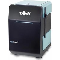
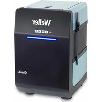
| Product Type | Soldering iron holder with Stop + Go control |
| Brand | Weller |
| Model | KHE 81 |
| Category | Soldering machine (accessory) |
| Mains voltage | 230 V AC |
| Power consumption | 3 W |
| Mains fuse | T 0.4 A (5x20 mm) |
| Protection class | 1 |
| Dimensions (control unit) | 137 x 75 x 90 mm |
| Estimated weight | Approx. 0.5 kg |
| Control type | Fiber optic (potential-free) |
| Control signal KHE 81 | LED for light transmission |
| Number of supported holders | 2 (one input must remain closed if only one is used) |
| Stop + Go function | Activates fume extraction when iron is removed, deactivates after 20 seconds |
| Temperature reduction | 150°C after 20 min of inactivity (digital stations) |
| Auto Off function | Shuts down after 60 minutes of inactivity (digital stations) |
| Light guide maintenance | Clean with denatured alcohol (KHE); can be shortened if damaged |
| Fuse replacement | Unscrew the control unit, fuse holder on the printed circuit board |
| Repairs | Only by authorized personnel |
| Delivery contents | Control unit, soldering iron holder with fiber optic, instruction manual, safety instructions |
| Compliance standards | 2004/108/EC, 2006/95/EC, 2011/65/EU (RoHS) |
Frequently Asked Questions - KHE 81 Weller
User questions about KHE 81 Weller
0 question about this device. Answer the ones you know or ask your own.
Ask a new question about this device
Download the instructions for your Welding machine in PDF format for free! Find your manual KHE 81 - Weller and take your electronic device back in hand. On this page are published all the documents necessary for the use of your device. KHE 81 by Weller.
USER MANUAL KHE 81 Weller
natural_image
Two black industrial electronic components with internal cavities and a coiled cable, shown against a white background (no text or symbols visible)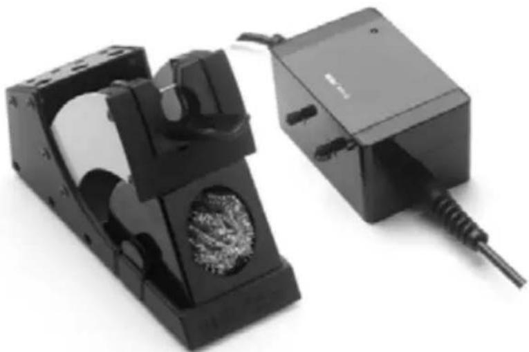
natural_image
Two black industrial electrical components with visible internal structures and wiring (no text or symbols)Betriebsanleitung - Mode d'emploi - Gebruiksaanwijzing - Istruzioni per l'uso - Operating Instructions - Instruktionsbok - Manual de uso - Betjeningsvejledning - Manual do utilizador - Käyttöohjeet - ОднгієсLambdaурац - Kullanım kılavuzu - Návod k použití - Instrukcja obsługi - Üzemeltetési utasítás - Návod na používanie - Navodila za uporabo - Kasutusjuhend - Naudojimo instrukcija - Lietošanas instrukcija - Ръководство за работа - Manual de exploatare Naputak za rukovanje
Inhaltsverzeichnis
Für Ablage KHE
Illustration support Stop + Go KHE
-
Attention! 5
-
Description 5
Illustration support Stop + Go KHP
-
Attention! 7
-
Description 7
Illustration of KHE Stop + Go
-
Caution! 17
-
Description 17
Technical data 17
-
Commissioning 17
-
Maintenance instructions 17
-
Operating guidelines 18
-
Scope of delivery 18
Table of contents Page
For KHP Rest
Illustration of KHP Stop + Go
-
Caution! 19
-
Description 19
Technical data 19
-
Commissioning 19
-
Maintenance instructions 19
-
Operating guidelines 20
-
Scope of delivery 20
natural_image
Two black electronic devices with internal components, one open and one connected to a cable (no visible text or symbols)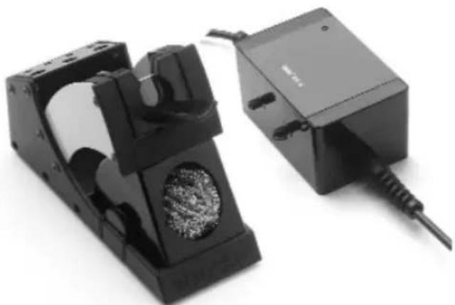
natural_image
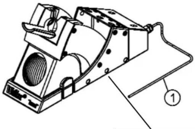
Two black electronic devices with internal components, one with a circular cutout and the other with a cable (no visible text or symbols)KHE 81 Safety rest
natural_image
Technical line drawing of a mechanical device with no visible text or symbols
- Lichtleiter
- LED Netzkontrolle
-
Steckdosenausgang
-
Fibre optique
- LED de contrôle du secteur
-
Sortie prise de courant
-
Lichtgeleider
- LED netspanning
-
Contactuitgang
-
Fibra ottica
- Spia LED per controllo tensione
-
Presa elettrica
-
Light guide
- Mains control LED
-
Socket outlet
-
Ljusledare
- Nätkontroll, lysdiod
-
Eluttgaets utgång
-
Conductor óptico
- LED de control de red
-
Salida de base de enchufe
-
Lysleder
- LED netkontrol
-
Stikdåseudgang
-
Condutor de luz
- LED Controlo de rede
-
Saída da tomada
-
valojohdin
- LED-merkkivalo
-
pistorasian ulostuloliitäntä
-
Φωτοαγωγός
- Έλεγχος του ηλεκτρικού δικτύου LED
-
Έξοδος του ρευματοδότη
-
Fiber optik kablo
- Sebeke kontrol LED'i
-
Priz çıkışı
-
Optický kabel
- Kontrolka LED síťového napájení
-
Zásuvka výstupu
-
Światłowód
- Dioda kontroli sieci
-
Wyjście gniazda wtykowego
-
optikai vezeték
- hálózatfigyelő LED
-
dugaszolóaljzat-kimenet
-
Optický kábel
- Kontrolka LED sietového napájania
-
Výstup zásuvky
-
Svetlobni vodnik
- Svetleča dioda za kontrolo omrežja
-
Vtični izhod
-
Valgusjuhe
- Võrgu kontroll-lamp
-
Pistikupesa väljund
-
Šviesolaidis
- Tinklo kontrolės indikatorius
-
Kištukinio lizdo išėjimas
-
Optiskais kabelis
- Tikla kontroles gaismas diode
-
Kontaktligzdas izeja
-
Светопроводник
- LED Контрол на мрежата
-
Изходен контакт
-
Cablu cu fibră optică
- LED control retea
-
leşire priză
-
Svjetlosni vodič
- LED nadzor mreže
- Izlaz za utičnicu

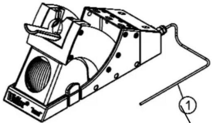
KHP 81 Safety rest
natural_image
Technical line drawing of a mechanical device with internal components and a numbered annotation (no text or symbols)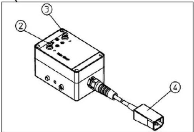
- Lichtleiter
- LED Netzkontrolle
- Druckluftanschluss (P) 3,5-7 bar
-
Druckluftausgang (A) für WFE
-
Light guide
- Mains control LED
- Compressed air connector (P), 3.5-7 bar
-
Compressed air outlet (A) for the WFE
-
Fibre optique
- LED de contrôle du secteur
- Raccord d'air comprime (P) 3,5-7 bars
-
Sortie d' air comprimé (A) pour WFE
-
Lichtgeleider
- LED netspanning
- Persluchtaansluitning (P) 3,5-7 bar
-
Persluchtuitgang (A) voor WFE
-
Fibre optique
- LED de contrôle du secteur
- Raccord d' air comprime (P) 3,5-7 bars
-
Sortie d' air comprimé (A) pour WFE
-
Ljusledare
- Nätkontroll, lysdiod
- Tryckluftanslutning (P) 3,5-7 bar
-
Trycklufttutgång (A) för WFE
-
Conductor óptico
- LED de control de red
- Empalme de aire comprimido (P), 3,5-7 bares
-
Salida de aire comprimido (A) para WFE
-
valojohdin
- LED-merkkivalo
- painertmaliitäntä (P) 3,5-7 bar
-
Painertman ulostuloliitäntä (A), WFE
-
Lysleder
- LED netkontrol
- Tryklufttilslutning (P) 3,5-7 bar
-
Trykluftudgang (A) til WFE
-
Φωτοαγωγός
- Έλεγχος του ηλεκτρικού δικτύου LED
- Σύνδεση του πεπιεσμένου αέρα (P) 3,5 - 7 bar
-
Έξοδος του πεπιεσμένου αέρα (Α) για τη συσκευή WFE
-
Condutor de luz
- LED Controlo de rede
- Conexão de ar comprimida (P) 3,5-7 bar
-
Saída de ar comprimido (A) para WFE
-
Fiber optik kablo
- Sebeke kontrol LED'i
- Basınçlı hava bağlantısı (P) 3,5-7 bar
-
WFE için basınçlı hava çıkışı (A)
-
Optický kabel
- Kontrolka LED síťového napájení
- Přívod stlačeného vzduchu (P) 3,5-7 bar
-
Výstup stlačeného vzduchu (A) pro WFE
-
Światłowód
- Dioda kontroli sieci
- Przyłącze spr żonego powietrza (P) 3,5-7 bar
-
Wyjście spr żonego powietrza (A) dla WFE
-
optikai vezeték
- hálózatfigyelő LED
- súrített levegő csatlakozója (P) 3,5-7 bar
-
sürített levegő kimenete (A) a WFE számára
-
Optický kábel
- Kontrolka LED sietového napájania
- Prípoj stlačeného vzduchu (P) 3,5-7 bar
-
Výstup stlačeného vzduchu (A) pre WFE
-
Svetlobni vodnik
- Svetleča dioda za kontrolo omrežja
- Priključek za komprimirani zrak (P) 3,5-7 bar
-
Izstop komprimiranega zraka (A) za napravo WFE
-
Valgusjuhe
- Võrgu kontroll-lamp
- Suruõhuühendus (P) 3,5-7 baari
-
Suruõhuväljund (A) WFE-le
-
Šviesolaidis
- Tinklo kontrolės indikatorius
- Suslègtojo oro jungtis (P) 3,5-7 bar
-
Suslėgtojo oro išėjimas (A) j WFE
-
Optiskais kabelis
- Tīkla kontroles gaismas diode
- Saspiestā gaisa pieslēgums (P) 3,5-7 bar
-
Saspiestā gaisa izeja (A), paredzēta WFE
-
Светопроводник
- LED Контрол на мрежата
- Присъединител за сгъстен въздух (Р) 3,5-7 бар
-
Изход за сгъстен въздух (A) за WFE1. Cablu cu fibră
-
LED control retea
- Racord de aer comprimat (P) 3,5-7 bari
-
leşire aer comprimat (A) pentru WFE
-
Svjetlosni vodič
- LED nadzor mreže
- Priključak komprimiranog zraka (P) 3,5 – 7 bara
- Izlaz komprimiranog zraka (A) za WFE
Thank you for placing your trust in our company by purchasing the Weller KHE / KHE 81 Stop + Go Rest. Production was based on stringent quality requirements which guarantee the perfect operation of the device.

1. Caution!
Please read these Operating Instructions and the attached Safety Information carefully prior to initial operation. Failure to observe the safety regulations results in a risk to life and limb.
The manufacturer shall not be liable for damage resulting from misuse of the machine or unauthorised alterations.
The Weller KHE / KHE 81 Stop + Go Rest corresponds to the EC Declaration of Conformity in accordance with the basic safety requirements of Directives 2004/108/EEC, 2006/95/EEC and 2011/65/EU /(RoHS).
2. Description KHE / KHE 81
The KHE / KHE 81 Stop + Go Rest is a switch-off and follow-up control for the WFE soldering fume extraction device.
The soldering iron rest has a zero-voltage guide connection to the control unit. In rest KHE 81, the light signal is transmitted to the control unit by an LED. In the case of rest KHE, the light inlet is located in the holder funnel.
The solder fume extractor cuts out approximately 20 sec. after the soldering gun is placed in the holder.
3. Commissioning
Check that the mains voltage is consistent with the information on the type plate. If the mains voltage is correct, plug the control unit into an earthed safety socket. The green LED (2) indicates that the system is ready to operate. The control unit is equipped for the operation of 2 soldering iron rests.
Technical Data
Mains voltage: 230 V AC
Power consumption: 3 W
Maximum breaking capacity: 100 W
Mains fuse: T 0.4A (5x20)
Protection Class: 1
Dimensions of control unit: 137 x 75 x 90
When being operated with one soldering iron rest only, the second light guide inlet has to be kept sealed. To connect the light guide (1) loosen the clamp nut and insert the light guide as far as the stop, then screw up the nut finger-tight. Next, insert the WFE mains cable into output socket (4) of the control unit and switch on.
KHE:
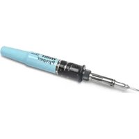
Place the FE soldering iron in the soldering gun holder and make sure that the light inlet (1) is completely covered by the soldering gun.
KHE 81:
Insert the soldering gun plug into the socket in the safety rest. Connect the safety rest connecting cable to the soldering station. To ensure that the over-run control device functions properly, the temperature of the soldering gun must be within the control range.
The solder fume extractor WFE shuts down after approx. 20 sec. The WFE restarts when the soldering gun is removed from the soldering gun holder.
Standard setback (in digital soldering stations)
If the soldering tool is not used within a period of 20 minutes the temperature will be automatically reduced to a standby temperature of 150^ C ( 300^ F). After three setback periods (60 min.) the "AUTO OFF" function will be activated and the soldering iron will be switched off.
4. Maintenance
To ensure that the device functions properly, it is important to ensure that the optical fibre (1) is connected correctly between the holder and the control unit. If the optical fibre is damaged, it can be cut to length again. In holders KHE, the light inlet in the holder funnel must be cleaned with alcohol (methylated spirit) at regular intervals.
If the light inlet of the optical fibre (1) is damaged, the optical fibre can be reinserted and cut to length again.
For this purpose, the screw fitting of optical fibre (1) on the soldering gun holder must be undone.
To replace the mains fuse, the control unit must be switched off and isolated from the mains and the 4 control unit casing bolts must be removed. The fuse holder for glass tube fuse (5x20) is on the circuit board.
Caution!
Repair work may only be performed by authorised specialist personnel.
5. Operating instructions
The operating instructions for the WELLER soldering tools used are applicable in conjunction with operating instructions.
6. Scope of supply
Control unit
Soldering iron rest with light guide
Operating Instructions
Safety Information
Subject to technical change without notice!
See the updated operating instructions at www.weller-tools.com.
Thank you for placing your trust in our company by purchasing the Weller KHP / KHP 81 Stop + Go Rest. Production was based on stringent quality requirements which guarantee the perfect operation of the device.

1. Caution!
Please read these Operating Instructions and the attached Safety Information carefully prior to initial operation. Failure to observe the safety regulations results in a risk to life and limb.
The manufacturer shall not be liable for damage resulting from misuse of the machine or unauthorised alterations.
The Weller KHP / KHP 81 Stop + Go Rest corresponds to the EC Declaration of Conformity in accordance with the basic safety requirements of Directives 2004/108/EEC, 2006/95/EEC and 2011/65/EU /(RoHS).
2. Description KHP / KHP 81
The KHP / KHP 81 Stop + Go Rest is a switch-off and follow-up control for the WFE soldering fume extraction device. The soldering iron rest has a zero-voltage guide connection to the control unit.
In rest KHP 81, the light signal is transmitted to the control unit by an LED. In the case of rest KHP, the light inlet is located in the holder funnel.
The solder fume extractor cuts out approximately 20 sec. after the soldering gun is placed in the holder.
3. Commissioning
Check that the mains voltage is consistent with the information on the type plate. If the mains voltage is correct, plug the control unit into an earthed safety socket. The green LED (2) indicates that the system is ready to operate. The control unit is
Technical Data
Mains voltage: 230 V AC
Power consumption: 6 W
Cutting-off pressure: 3.5-7 bars
Mains fuse: T 0.4 A (5x20)
Protection Class: 2
Dimensions of control unit: 137 x 75 x 90
equipped for the operation of 2 soldering iron rests.
When being operated with one soldering iron rest only, the second light guide inlet has to be kept sealed. To connect the light guide (1) loosen the clamp nut and insert the light guide as far as the stop, then screw up the nut finger-tight. Now connect the compressed air supply (3) and the WFE P to the compressed air outlet (4) and turn on the fume extractor.
KHP:
Place the FE soldering iron in the soldering gun holder and make sure that the light inlet (1) is completely covered by the soldering gun.
KHP 81:
Insert the soldering gun plug into the socket in the safety rest. Connect the safety rest connecting cable to the soldering station. To ensure that the over-run control device functions properly, the temperature of the soldering gun must be within the control range.
The solder fume extractor WFE shuts down after approx. 20 sec. The WFE restarts when the soldering gun is removed from the soldering gun holder.
Standard setback (in digital soldering stations)
If the soldering tool is not used within a period of 20 minutes the temperature will be automatically reduced to a standby temperature of 150^ C ( 300^ F). After three setback periods (60 min.) the "AUTO OFF" function will be activated and the soldering iron will be switched off.
4. Maintenance
To ensure that the device functions properly, it is important to ensure that the optical fibre (1) is connected correctly between the holder and the control unit. If the optical fibre is damaged, it can be cut to length again. In holders KHP, the light inlet in the holder funnel must be cleaned with alcohol (methylated spirit) at regular intervals.
If the light inlet of the optical fibre (1) is damaged, the optical fibre can be reinserted and cut to length again.
For this purpose, the screw fitting of optical fibre (1) on the soldering gun holder must be undone.
To replace the mains fuse, the control unit must be switched off and isolated from the mains and the 4 control unit casing bolts must be removed. The fuse holder for glass tube fuse (5x20) is on the circuit board.
Caution!
Repair work may only be performed by authorised specialist personnel.
5. Operating instructions
The operating instructions for the WELLER soldering tools used are applicable in conjunction with operating instructions.
6. Scope of supply
Control unit
Soldering iron rest with light guide
Operating Instructions
Safety Information
Subject to technical change without notice!
See the updated operating instructions at www.weller-tools.com.
Apex Tool Group S.N.C.
25 Av. Maurice Chevalier B.P. 46
77832 Ozoir-la-Ferrière, Cedex
Phone:+33 (0) 1.64.43.22.00
Fax: +33 (0) 1.64.43.21.62
ITALY
Apex Tool S.r.l.
Viale Europa 80
20090 Cusago (MI)
Phone: +39 (02) 9033101
Fax: +39 (02) 90394231
SWITZERLAND
Apex Tool Switzerland Sàrl
Crêt-St-Tombet 15
2022 Bevaix
Phone: +41 (0) 24 426 12 06
Fax: +41 (0) 24 425 09 77
INDIEN
Apex Power Tools India Pvt. Ltd.
Regus business centre,
Level 2, Elegance, Room no. 214
Mathura Road, Jasola
New Delhi - 110025
FRANCE
Apex Tool Group S.N.C.
25 Av. Maurice Chevalier B.P. 46
77832 Ozoir-la-Ferrière, Cedex
Phone:+33 (0) 1.64.43.22.00
Fax: +33 (0) 1.64.43.21.62
CANADA
Apex Tools - Canada
5925 McLaughlin Rd. Missisauga
L5R 1B8 Ontario
Fax: +1 (905) 387-2640
CHINA
Apex Tool Group
A-8 Building, No. 38 Dongsheng Road
Heqing Industrial Park, Pudong
Shanghai 201201
Phone: +86 (21) 60 88 02 88
Fax: +86 (21) 60 88 02 89
USA
Apex Tool Group, LLC
14600 York Rd. Suite A
Sparks, MD 21152