AC33024 - Compressor Senco - Free user manual and instructions
Find the device manual for free AC33024 Senco in PDF.

| Product Type | Oil-free Air Compressor |
| Brand | Senco |
| Model | AC33024 |
| Power Supply Voltage | 230 V / 50 Hz |
| Rated Current | 9.6 A |
| Rated Power | 2.2 kW (2.0 kW depending on version) |
| Maximum Working Pressure | 10.5 bar |
| Operating Pressure | 7 to 10 bar (automatic start/stop) |
| Tank Volume | 24 liters |
| Air Flow (intake / output) | 330 l/min / 200 l/min |
| Rotation Speed | 1400 rpm |
| Sound Pressure Level | 79.6 dB(A) (A-weighted) |
| Total Weight | 36 kg |
| Dimensions (L × W × H) | 477 × 793 × 477 mm (approx) |
| Operating Ambient Temperature | +5 °C to +40 °C |
| Ambient Humidity | 5 % to 95 % |
| Safety Devices | Safety valve (10.5 bar), pressure switch, resettable thermal protection, fan guard |
| Daily Maintenance | Drain condensate from tank after each work cycle |
| Weekly Maintenance | Clean air filters, check wheel pressure (max 2.5 bar) |
| Spare Parts | Use only genuine Senco parts |
| Authorized Uses | Pneumatic tools (inflation guns, washing, sandblasting, etc.) |
Frequently Asked Questions - AC33024 Senco
User questions about AC33024 Senco
0 question about this device. Answer the ones you know or ask your own.
Ask a new question about this device
Download the instructions for your Compressor in PDF format for free! Find your manual AC33024 - Senco and take your electronic device back in hand. On this page are published all the documents necessary for the use of your device. AC33024 by Senco.
USER MANUAL AC33024 Senco
Operating Instructions
(Translation of Original Instructions)
Betriebsanleitung
natural_image
Exterior view of a Siemens air conditioner unit with wheels and control panel (no visible text or symbols)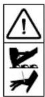
WARNING: Please read the instructions and warnings for this tool carefully before use.

| EN | English | 3 |
| DE | Deutsch | 13 |
| FR | Français | 24 |
| NL | Nederlands | 35 |
| PT | Português | 46 |
| ES | Español | 57 |
| IT | Italiano | 68 |
| GR | Ελληνικά | 79 |
| SE | Svenska | 90 |
| NO | Norsk | 101 |
| FI | Suomi | 111 |
| DK | Dansk | 121 |
| RU | Русский | 131 |
| EE | Eesti | 142 |
| LT | Lietuviškai | 152 |
| LV | Latviešu | 162 |
| PL | Polski | 173 |
| CZ | Ceština | 184 |
| SK | Slovenský | 194 |
| HU | Magyar | 205 |
| SI | Slovenščina | 216 |
| RO | Română | 226 |
| BG | Български | 236 |
| TR | Türkçe | 247 |
TABLE OF CONTENTS
- IMPORTANCE OF THE MANUAL......4
- RECIPIENTS......4
- STATUS "APPLIANCE OFF" 4
- INTENDED USE ....5
- INCORRECT USE ....5
- TRANSPORTATION AND MOVEMENT OF THE APPLIANCE....5
- PACKAGING ....5
- UNPACKING......5
- LOCATION 5
- STORAGE ....6
- ELECTRICAL CONNECTION....6
- AIR PIPE (EXTENSION) AND UTENSILS CONNECTION ....6
- SAFETY DEVICES ADOPTED ....6
- SAFETY SIGNS ....7
- PERSONAL PROTECTIVE EQUIPMENT (PPI)....7
- RESIDUAL RISKS....7
- AREAS ASSUMED BY AUTHORISED OPERATORS....7
- COMMAND DEVICES....8
- PRE-START-UP CHECKS......8
- APPLIANCE ACTIVATION ....8
- APPLIANCE DEACTIVATION....9
- RESET INTERVENTION – THERMAL RESTORE....9
- EMERGENCY STOP 9
- START-UP SUBSEQUENT TO AN EMERGENCY STOP ....9
- STANDARD MAINTENANCE....9
- EXTRAORDINARY MAINTENANCE 10
- END OF SERVICE LIFE.... 10
- REPLACEMENT PARTS.... 10
- ANOMALIES - CAUSES - SOLUTIONS.... 10
- TECHNICAL SPECIFICATIONS 12
- CE LABEL.... 12
1. IMPORTANCE OF THE MANUAL

BEFORE USING THE APPLIANCE IN QUESTION, AUTHORISED USERS MUST READ AND UNDERSTAND THE PRESENT INSTRUCTION MANUAL IN ITS ENTIRETY.
- The "Instruction Manual" was compiled according to the instructions as specified in Machinery Directive 2006/42/CE, in order to guarantee easy and correct understanding of subjects relevant to operators authorised to use and oversee maintenance of the appliance in question. Should operators find errors, please do not send incorrect personal interpretations/amendments that may threaten safety, rather, we advise you immediately request the Manufacturer send the correct explanations or further details.
- The "Instruction Manual" must be accessible by authorised operators at all times and must be always be kept in a safe place within close proximity of the appliance.

THE PRESENT INSTRUCTION MANUAL FORMS AN INTEGRAL PART OF THE APPLIANCE AND MUST BE KEPT FOR FUTURE REFERENCE AND UP UNTIL THE
END OF APPLIANCE LIFE. IT MUST ALWAYS BE ACCESSIBLE TO AUTHORISED OPERATORS AND IT MUST BE SAFELY STORED AND KEPT WITHIN CLOSE PROXIMITY OF THE APPLIANCE ITSELF.
THE MANUFACTURER DECLINES ANY RESPONSIBILITY FOR DAMAGE TO PERSONS, ANIMALS AND OBJECTS CAUSED BY INOBSERVATION OF REGULATIONS AND WARNINGS DESCRIBED IN THE PRESENT INSTRUCTION MANUAL.
IN THE INSTANCE WHERE THE INSTRUCTION MANUAL IS LOST OR DAMAGED, RERQUEST A COPY FROM THE MANUFACTURER OR THE AUTHORISED SUPPLIER, SPECIFYING THE APPLIANCE MODEL AND THE EDITION NUMBER PROVIDED WITHIN THE TITLE.
THE PRESENT INSTRUCTION MANUAL COMPLIES WITH TECHNICAL PROVISIONS AT THE TIME OF PURCHASE OF THE APPLIANCE AND CANNOT BE CONSIDERED INCORRECT IN THE INSTANCE WHERENEWEXPERIMENTATION RESULTS IN UPDATES OF SUCH TECHNICAL PROVISIO.
THE PRESENT INSTRUCTION MANUAL MUST BE PASSED OVER IN THE INSTANCE WHERE THE APPLINACE IS HANDED OVER TO ANOTHER USER.
2. RECIPIENTS
- This "Instruction Manual" is aimed exclusively at operators authorised to carry out operations according to specific technical skills necessitated for the operation type.
- The below described symbols appear at the beginning of paragraphs in order to indicate the identity of operators affected by the subject described.

AUTHORISED OPERATORS MUST ONLY CARRY OUT OPERATIONS FOR WHICH THEY ARE QUALIFIED. BEFORE CARRYING OUT ANY OPERATIONS, AUTHORISED OPERATORS MUST POSSESS
ADEQUATE PSHYCHO-PHYSICAL CAPABILITES IN ORDER TO ALWAYS ENSURE SAFETY.
ASSIGNED OPERATOR: An operator over the age of 18 (private user or employee) and, who, in compliance with current legislation on health and safety in the work place in force within the country of usage, is capable of exclusively activating, using

and deactivating the appliance whilst completely complying with the instructions presently provided, whilst using the dedicated personal safety device items.
MECCHANICAL/PNEUMATIC MAINTENANCE
PERSON: A qualified technician, capable of carrying out exclusive interventions on mechanical/pneumatic parts in order to oversee the regulation, maintenance and/or repairs even with protective devices disabled in complete compliance with the instructions presently provided or with any other specific document supplied by the Manufacturer, whilst using the dedicated personal safety device items.
ELECTRICAL MAINTENANCE: A qualified technician, capable of carrying out exclusive interventions on electrical devices in order to oversee the regulation, maintenance and/or repairs even where an electric supply is present and even with protective devices disabled in complete compliance with the instructions presently provided or with any other specific document supplied by the Manufacturer, whilst using the dedicated personal safety device items.
COMPANY SAFETY MANAGER: A qualified technician nominated by the employer (where the appliance is used in a business context), who possesses the required professional, technical skills as specified by the legislations currently in force on health and safety of workers at the work place.
MANUFACTURER'S TECHNICIAN: A qualified technician offered by the Manufacturer and/or Supplier authorised to provide required technical assistance, standard and extraordinary maintenance interventions and/or operations which are not presently included which necessitate specialist knowledge of the appliance, whilst using the dedicated personal safety device items.

3. STATUS "APPLIANCE OFF"
Before carrying out any type of maintenance and/or regulation operation on the appliance, you must:
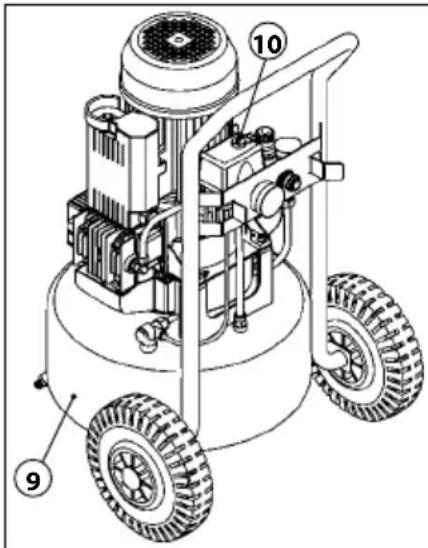
1) Shut off the power supply ensuring that the "ON-OFF" switch (10) is in the "OFF (0)" position.
2) Unplug the power cable from the plug located near the appliance.
3) Empty the tank (9) (no pressure).


4. INTENDED USE
FIELD OF OPERATION
Industrial, handicraft and civil.
PLACE OF OPERATION
Interior locations with sufficient lighting, ventilation, with temperature and air humidity values as per details provided in Paragraph 30, in compliance with legislation governing health and safety in the work place in force in the country of usage. The appliance must rest on a surface that ensures the appliance is stable with respect to its weight and overall dimensions (see Paragraph 30).

WARNING! THE APPLIANCE MUST BE KEPT OUT OF REACH OF CHILDREN.
INTENDED USE
Compressing air (no oil) to be used with suitable pneumatic utensils according to current legislation in force (E.g. blowing, pumping, washing, veneering and sandblasting, etc.).
OPERATORS AUTHORISED USE
An authorised operator with professional, technical skills as described in Paragraph 2.
5. INCORRECT USE
The appliance was designed and manufactured exclusively for the aim as described in Paragraph 4; in order to ensure the safety of authorised operators and appliance efficiency at all times, any other use is completely forbidden.

IT IS COMPLETELY FORBIDDEN TO OPERATE THE APPLIANCE IN ENVIRONMENTS PRONE TO EXPLOSIONS AND/OR WHERE COMBUSTIBLE
SUBSTANCES ARE PRESENT (E.G. WOOD GRAINS, FLOUR, SUGAR AND GRANULES).
IT IS ABSOLUTELY FORBIDDEN TO USE THE MACHINE IN AREAS CONTAINING SOLID OR ABRASIVE PARTICLES.
DANGER OF BURNS UPON ACCIDENTAL CONTACT WITH TWIN CYCLINDER PUMP SYSTEM AND ELECTRIC MOTOR. WARNING – RESIDUAL RISK (SEE PARAGRAPH 16).
THE MACHINE MUST BE USED IN COMPLIANCE WITH LEGIS-LATION GOVERNING EMISSIONS (NOISE) IN FORCE IN THE COUNTRY OF USE.
DURING USE, ENSURE THAT UNAUTHORISED PERSONS DO NOT COME WITHIN PROXIMITY OF THE APPLIANCE.
THE APPLIANCE MUST BE KEPT OUT OF THE REACH OF CHILDREN.
INCORRECT USE OF THE APPLIANCE OR USE WHICH DIFFERS FROM THAT SPECIFIED IN PARAGRAPH 4 IS FORBIDDEN.
THE USE OF UNSUITABLE AIR PIPES (EXTENSIONS), CONNECTIONS AND UTENSILS OR THOSE WHICH DO NOT CONFORM WITH CURRENT LEGISLATION IN FORCE ARE COMPLETELY FORBIDDEN.
IT IS FORBIDDEN TO LIFT THE APPLIANCE WITH CRANES AND/OR LIFTING DEVICES.
IT IS FORBIDDEN TO DIRECT COMPRESSED AIR JETS AT PERSONS AND/OR ANIMALS.
IT IS FORBIDDEN TO USE THE APPLIANCE TO MOVE AND/OR LIFT PERSONS, ANIMALS OR OBJECTS.
IT IS FORBIDDEN TO MOUNT THE APPLIANCE.
IT IS FORBIDDEN TO TOW THE APPLIANCE USING ANY TYPE OF MEDIUM AND/OR VEHICLE.
IT IS FORBIDDEN TO MANUALLY MOVE THE APPLIANCE UPHILL AND/OR DOWNHILL WHERE DANGEROUS INCLINATIONS ARE PRESENT.
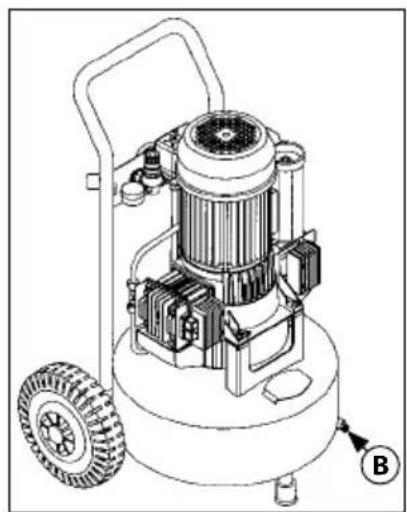
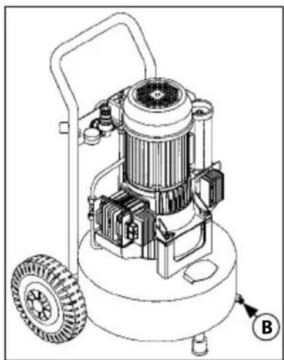
6. TRANSPORTATION AND MOVEMENT OF THE APPLIANCE
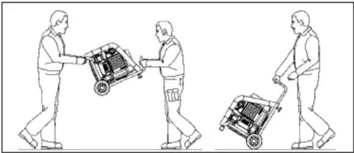
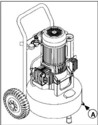
The appliance may be manually transported by two qualified operators, gripping it by the foot (A) and the handle (B) or manually moved by a qualified operator using the handles (C) and the wheels (D) which feature as part of the appliance.

TRANSPORTATION OF THE APPLIANCE MUST BE CARRIED OUT BY TWO QUALIFIED OPERATORS IN COMPLIANCE WITH REGULATIOSNS OVERSEEING
"MANUAL MOVEMENT OF LOADS" IN ORDER TO AVOID UNFAVOURABLE ERGONOMIC CONDITIONS WHICH COULD LEAD TO THE RISK OF BACK INJURIES.
natural_image
Three line drawings of people pushing carts with luggage, no text or symbols present7. PACKAGING
The appliance is packaged by the Manufacturer within a cardboard box equipped with two handles containing one compressor and one use and maintenance instruction manual.
8. UNPACKING
Once the package has been placed on the floor on a flat surface which ensures stability, proceed with unpacking; remove the appliance from its packaging as per the instructions provided in Paragraph 6.

PLEASE DISPOSE OF THE PACKAGING DIVIDING IT UP ACCORDING TO THE VARIOUS WASTE MATERIALS AND IN COMPLIANCE WITH LEGISLATION CURRENT-ORCE IN THE COUNTRY OF USAGE.
9. LOCATION
The appliance must be placed in a work place which satisfies the characteristics described in Paragraph 4; it must be placed on a flat surface which ensures stability with regards to overall dimensions and weight (see Paragraph 30).

IN ORDER TO ENSURE A SAFE WORKING ENVIRONMENT FOR AUTHORISED OPERATORS, WE RECOMMEND PLACING THE APPLIANCE AT A MINIMUM NCE OF 1m FROM OTHER OBJECTS/ENTITIES.
EN
10. STORAGE
- In the instance where the appliance is not to be used for an extended period of time, it must be stored in a safe place, with suitable temperature and air humidity values, where it is protected from dust.
- Before storing the appliance, we recommend draining moisture from the air tank.
11. ELECTRICAL CONNECTION
The machine can be connected to the mains electrical supply by plugging the power cable into the special socket.

THE POWER SUPPLY NETWORK TO WHICH THE APPLIANCE IS CONNECTED MUST CONFORM TO THE LEGISLATION CURRENTLY IN FORCE IN THE COUNTRY OF USAGE, CONFORM TO THE TECHNICAL SPECIFICATIONS PROVIDED IN PARAGRAPH 2 AND BE EQUIPPED WITH A SUITABLE "PLANT EARTHING" SYSTEM.
ALL MATERIALS USED FOR ELECTRICAL CONNECTION MUST BE SUITED TO THE INTENDED USAGE, LABELLED WITH "CE" IF SUBJECT TO THE LOW VOLTAGE DIRECTIVE 2006/95/CE AND CONFORM TO THE REQUIREMENTS AS SPECIFIED IN THE LEGISLATION CURRENTLY IN FORCE IN THE COUNTRY OF APPLIANCE USAGE.
DISREGARD FOR THE ABOVE DESCRIBEDWARNINGS MAY LEAD TO IRREPERABLE DAMAGE TO THE APPLIANCE ELECTRICAL SYSTEM AND SUBSEQUENTLY WARRANTY EXPIRY.
THE MANUFACTURER DECLINES ANY RESPONSIBILITY FOR FAULTS OR ANOMOLIES WITH APPLIANCE OPERATION CAUSED BY ELECTRICAL POWER SURGES IN ADDITION TO TOLERANCES BY THE SUPPLY ENTITY (VOLTAGE ± 10%, FREQUENCY ± 2%).
WHERE NECESSARY, CONNECT THE APPLIANCE EXCLUSIVELY TO THE ELECTRICAL SUPPLY GENERATOR WITH POWER GRTEATER THAN THE INSTALLED ELECTRICAL POWER (SEE PARAGRAPH 30), IN ORDER TO SUPPORT THE POWER-DRAWAT START-UP.
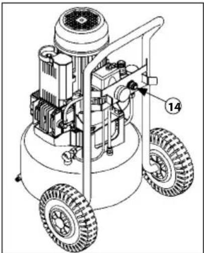
12. AIR PIPE (EXTENSION) AND UTENSILS CONNECTION
1) Connect the utensil to the air pipe (extension).
2) Connect the air pipe (extension) to the appliance air outlet spigot (rif. 14).

THE MANUFACTURER DECLINES ANY RESPONSIBILITY FOR DAMAGE TO PERSONS, ANIMALS AND OBJECTS CAUSED BY THE INOBSERVATION OF THE ABOVE DESCRIBEDWARNINGS.
AIR PIPES (EXTENSION), CONNECTIONS AND UTENSILS WHICH CONFORM TO THE MANUFACTURER'S INSTRUCTION MANUALS MUST BE USED.
THE USE OF UNSUITABLE AIR PIPES (EXTENSIONS), CONNECTIONS AND UTENSILS AND/OR THOSE WHICH DO NOT COMPLY WITH LEGILATION CURRENTLY IN FORCE IS STRICTLY FORBIDDEN.
natural_image
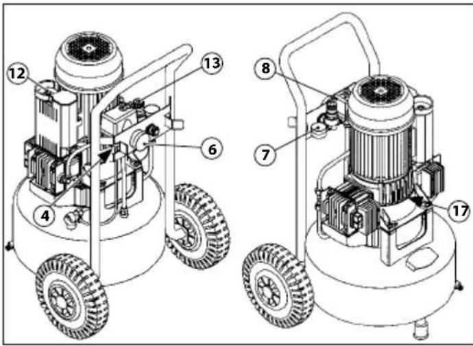
Technical line drawing of a mechanical device with four wheels and a central component (no text or symbols)13. SAFETY DEVICES ADOPTED
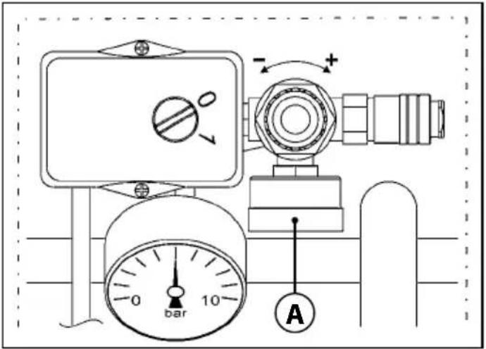
1) SAFETY VALVE (4): a certified safety valve (set to 10.5 bar), installed to the pneumatic system, under the pressure switch. It tackles over-pressure in the instance where, owing to anomalies, the pressure switch does not function. Safety valve intervention ensures the operator switches off the appliance and requests the support of maintenance persons.
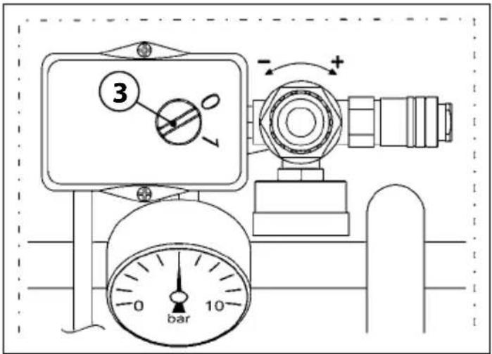
2) PRESSURE SWITCH (8): an electro-pneumatic device (set to a minimum of 7 bar and a maximum of 10 bar) installed to the pneumatic system. It serves to control the automatic start-up of the appliance when the operating pressure comes down to 7 bar and the automatic close-down when the pressure reaches 10 bar.
3) FIXED COOLING FAN PROTECTIVE NET (17): fixed protection made of plastic attached using screws fixed to the twin cylinder pump system base. It serves to stop accidental contact with the cooling fan when in motion.
4) THERMAL RESTORE (12): thermal protection installed to the electrical system, which stops the electric motor in the instance of power overload and/or a short-circuit. Reset can be carried out by acting on the relative button (A).
5) TANK PRESSURE GAUGE (6): a measuring device installed to the appliance tank. It displays the compressed air pressure inside the tank.
6) OUTLET PRESSURE GAUGE (7): a measuring device installed to the appliance pneumatic system above the air outlet spigot. It displays the outlet pressure, which can be adjusted using the relative pressure regulator (0÷10 bar) (13).

ALL SAFETY DEVICES INSTALLED ON THE APPLIANCE MUST BE REGULARLY CHECKED TO ENSURE THEY ARE FUNCTIONING CORRECTLY.
ANY SAFETY DEVICES WHICH ARE NOT FUNCTIONING CORRECTLY OR WHICH ARE DAMAGED MUST BE IMMEDIATELY REPLACED.
THE HANDLING, EXCLUSION AND/OR REMOVAL OF SAFETY DEVICES INSTALLED ON THE DEVICE IS STRICTLY FORBIDDEN.
REPLACING A SAFETY DEVICE OR COMPONENTS OF SAFETY DEVICES WITH UNORIGINAL REPLACEMENT PARTS IS STRICTLY FORBIDDEN.
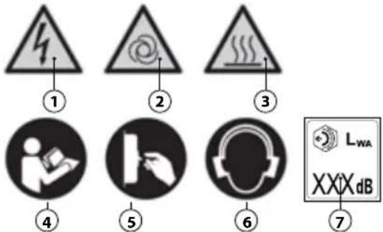
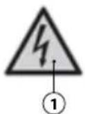
14. SAFETY SIGNS
Safety signs used take the form of a sticky label, applied to the appliance exterior.
Sign definitions:
① Warning – electrical power.
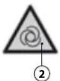
② Warning – automatic start-up.
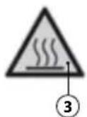
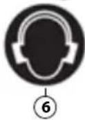
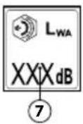
③ Warning – high temperature.
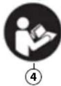
4 Instructions must be read.
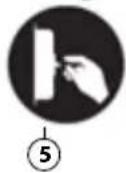
⑤ Power must be disconnected.
⑥ Protect your hearing.
⑦ Guaranteed sound power level.

THE SAFETY SIGN MUST BE KEPT CLEAN SO THAT IT IS VISIBLE.
SAFETY SIGNS WHICH ARE DAMAGED MUST BE REPLACED; ASK FOR A REPLACAMENT FROM THE MANUFACTRER OR THE AUTHORISED SUPPLIER.
REMOVING AND/OR DAMAGING THE SAFETY SIGN AT- TACHED TO THE APPLIANCE IS STRICTLY FORBIDDEN.
15. PERSONAL PROTECTIVE EQUIPMENT (PPI)

PERSONAL PROTECTIVE EQUIPMENT ISSUED BY THE MANUFACTURER MUST BE USED.
AUTHORISED OPERATORS MUST WEAR PERSONAL PROTECTIVE EQUIPMENT ISSUED BY THE MANUFACTURERS OF THE UTENSILS EMPLOYED BASED UPON THE WORK TO BE CARRIED OUT.
AUTHORISED OPERATORS MUST NOT WEAR CLOTHING AND/OR ACCESSORIES THATMAY BECOME CAUGHT IN THE APPLIANCE.
| SIGN COMPULSORY PPE | TYPE OF WORK | |
 | Hand protection (heat-resistant gloves) | In the instance where maintenance interventions have to be carried out whilst the electric motor and the twin cylinder pump system are still hot. |
 | Ear protectors (earmuffs) | During all operational phases. |
 | Feet protection (shoes with reinforced toe caps) | During appliance transportation. |
16. RESIDUAL RISKS
Although the Manufacturer has adopted all technical construction solutions in order to make the appliance as safe as possible, authorised operators please be aware that residual risks remain.
| RESIDUAL RISK Danger of burns upon accidental contact with the twin cylinder pump system and the electric motor. | |
| SEVERITY OF DAMAGE | Mild damage (normally reversible). |
| LIABILITY Liability may be incorporated in the instance when the operator decides to voluntarily carry out an incorrect or forbidden action. | |
| PROBABILITY Small and accidental. | |
| PHASE IN WHICH THE RISK IS PRESENT | Operation. |
| SUITABLE PROVISIONS | Safety signs (see Paragraph 14). Commitment to use personal protection equipment (PPI) (see Paragraph 15) and/or waiting for the appliance to cool. |
17. AREAS ASSUMED BY AUTHORISED OPERATORS
AREA A: on the rear side of the appliance next to the command devices, in order to command the activation and deactivation of the compressor, to carry out connection/disconnection of the utensils, reading of the gauge and the regulation of the pressure, cleaning or replacement of the air filter and opening/closure of the condensate pump.
AREA B: when working to carry out suitable operation dependent on the type of utensil used (E.g. veneering, etc.).
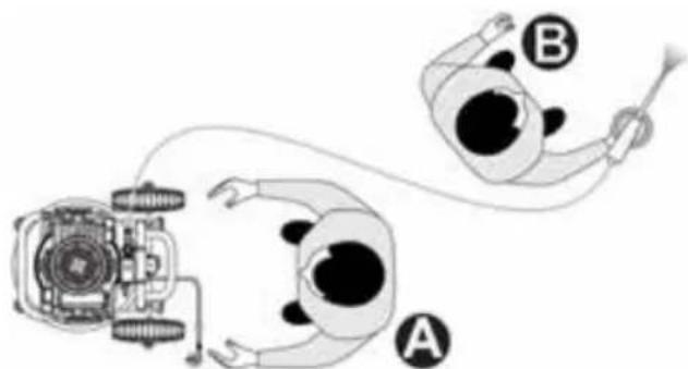
natural_image
Diagram of two figures with labeled parts, one holding a tool and the other holding a device (no text or symbols present)EN
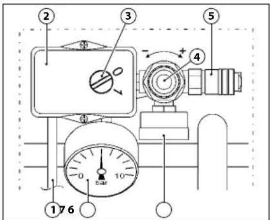
18. COMMAND DEVICES
The command devices are:
① Electrical supply cable
② Pressure switch
③ "ON-OFF" switch
④ Outlet pressure regulator
⑤ Air outlet spigot
⑥ Tank pressure gauge
⑦ Tank outlet gauge
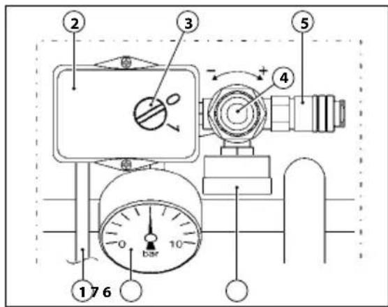
19. PRE-START-UP CHECKS

BEFORE STARTING UP THE APPLIANCE, AUTHORISED OPERATORS MUST CARRY OUT THE FOLLOWING CHECKS.
- Ensure that no unauthorised persons are in close proximity of the appliance.
- Ensure that safety devices are not damaged and that they are correctly installed and operational (see Paragraph 13).
- Ensure that the appliance is correctly positioned (see Paragraph 9).
- Ensure that the "ON-OFF" switch is in the "OFF (0) position (see Paragraph 18).
- Ensure that the condensate pump is closed (5).

natural_image
Technical line drawing of a mechanical pressure pump with wheels and internal components (no text or symbols)- Use the compulsory personal protection equipment (PPI) (see Paragraph 15).
- Ensure that you have read and understood all parts of the present "Instruction Manual".
20. APPLIANCE ACTIVATION

DANGER OF BURNS UPON ACCIDENTAL CONTACT WITH THE TWIN CYLINDER PUMP SYSTEM AND ELECTRIC MOTOR. WARNING – RESIDUAL RISK (SEE PARAGRAPH 16).
THE MANUFACTURTER DECLINES ANY RESPONSIBILITY FOR DAMAGE TO PERSONS, ANIMALS OR OBJECTS CAUSED BY INOBSERVANCE OF REGULATIONS AND THEWARNINGS DESCRIBED IN THE PRESENT MANUAL.
THE MANUFACTURTER DECLINES ANY RESPONSIBILITY FOR THE OUTCOME FOLLOWING USAGE AS THIS IS DEPENDENT ON THE UTENSIL USED AND THE PROFESSIONAL SKILLS OF THE AUTHORISED OPERATORS.
THE AUTHORISED OPERATORS MAY ONLY START UP THE APPLIANCE ONLY AFTER HAVING CARRIED OUT THE COMPLULSARY CHECKS DESCRIBED IN PARAGRAPH 19.
BEFORE USING THE APPLIANCE IN QUESTION, AUTHORISED OPERATORS MUST READ AND UNDERSTAND ALL PARTS OF THE PRESENT MANUAL.
DURING OPERATION, PLEASE ENSURE THAT UNAUTHORISED PERSONS DO NOT COME WITHIN PROXIMITY OF THE APPLIANCE.
AUTHORISED OPERATORS MUST NOT LEAVE THE APPLIANCE UNSUPERVISED WHilst IN OPERATION OR DURING MAINTENNACE INTERVENTIONS.
1) Connect the appliance to the power supply (1) by plugging it in.
2) Switch on the appliance using the "ON-OFF" switch (3) ensuring it is in the "ON (I)" position (the appliance is operational until it reaches a maximum operating pressure of 10 bar, after which, it switches off automatically.
3) Regulate the outlet pressure using the relevant regulator (4) according to the utensil used and type of work. Control the pressure displayed by the relevant gauge (6).

DO NOT FULLY SCREW THE OULET PRESSURE GAUGE (4) OR YOU RISK DAMAGING THE MEMEBRANE.
4) Connect the utensil to the air pipe (extension).
5) Connect the air pipe (extension) to the air outlet spigot (5)

AIR PIPES (EXTENSIONS), CONNECTIONS AND UTENSILS WHICH CONFORM TO DETAILS AS SPECIFIED IN THE INSTRUCTION MANUALS PROVIDED BY THE RELEVANT MANUFACTURERS MUST BE USED.
IT IS STRICTLY FORBIDDEN TO USE UNSUITABLE AIR HOSES (EXTENSIONS), FITTINGS AND TOOLS THAT DO NOT COMPLY WITH CURRENT REGULATIONS.
6) Carry out operations (the appliance will re-start automatically in the instance where the operating pressure falls below 7 bar).
7) Upon termination of operations, switch off the appliance as described in Paragraph 21.
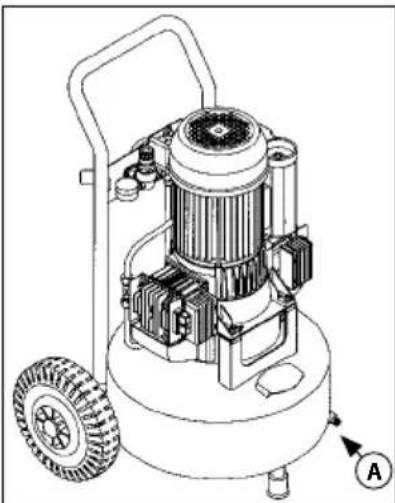
21. APPLIANCE DEACTIVATION
At the end of operations, switch off the appliance as follows:
1) Switch off the appliance using the "ON-OFF" switch (3) ensuring it is set to "OFF (0)".
2) Disconnect the appliance from the power supply (1) by unplugging it.
3) Disconnect the utensil from the air pipe (extension).
4) Disconnect the air pipe (extension) from the appliance air outlet spigot (5).
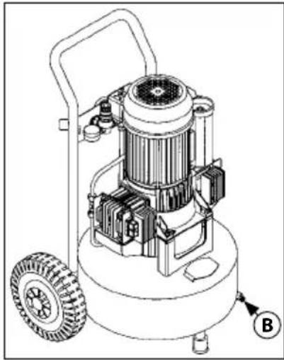
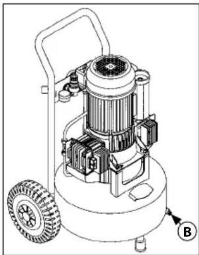
5) Drain the tank condensate pump only once the work cycle is terminated (A)..
natural_image
Technical line drawing of a mechanical device with wheels and internal components (no text or symbols)22. RESET INTERVENTION - THERMAL RESTORE
In the instance where current overload and/or a short circuit of the appliance electrical system is noted, the thermal restore intervenes, disabling the electric motor. To carry out the reset intervention, proceed as follows:
1) Turn the "ON-OFF" switch (3) to the "OFF (0)" position.
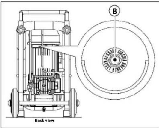
2) Press the thermal restore button (B).
3) Wait a few moments before restarting the appliance.

IF, AFTER CARRYING OUT THERMAL RESTORE, THE APPLIANCE DOES NOT RESTART, THE QUALIFIED OPERATOR MUST REQUEST THE INTERVENTION OF
MAINTENANCE PERSONS AND/OR THE AUTHORISED SUPPLIER.
23. EMERGENCY STOP
Appliance emergency stop can be carried out by turning the "ON-OFF" switch (3) to the "OFF (0)" position.
In order to avoid any possible danger, authorised operators must carry out the following operations.
1) IMMEDIATELY BRING THE "ON-OFF" SWITCH TO THE "OFF (0)" POSITION (3).
2) IMMEDIATELY NOTIFY THE "SAFETY MANAGER" (WHERE THE APPLIANCE IS USED IN A BUSINESS CONTEXT) OF THE EMERGENCY.
24. START-UP SUBSEQUENT TO AN EMERGENCY STOP
After having resolved the issues which offset the emergency, and checked that no damage and/or anomalies have been caused to the appliance, with the consent of the safety manager (where the appliance is used in a business context) start the appliance as described in Paragraph 20.
25. STANDARD MAINTENANCE
All activities carried out to ensure use and operation of the appliance, via various intervention types (regulation, valve checks, cleaning of air filters, etc.) executed by the authorised maintenance person according to pre-established time intervals.

AUTHORISED OPERATORS MUST ONLY CARRY OUT OPERATIONS FOR WHICH THEY ARE QUALIFIED (SEE PARAGRAPH 2) AND WITH THE CONSENT OF THE
SAFETY MANAGER (WHERE THE APPLIANCE IS USED IN A BUSINESS CONTEXT).
IT IS FORBIDDEN FOR AUTHORISED OPERATORS TO LEAVE THE APPLIANCE UNSUPERVISED DURING OPERATION AND MAINTENANCE INTERVENTIONS.
EN
| STANDARD MAINTENANCE TABLE | ||
| FREQUENCY | INTERVENTION AREA | INTERVENTION TYPE |
| ONCE A DAY | Safety devices. | Ensure they are intact, correctly installed and functioning. |
| Electrical cable and plug. | Visual check of usage status. | |
| Tank. Upon termination of each work cycle, rest the appliance on the ground and drain the tank condensate pump opening the condensate pump (A). | ||
| EVERY WEEK | Wheels. Wheel pressure check.Subsequently pump up with compressed air up to a maximum of 2.5 bar. | |
| N. 2 air filters. | Unscrew the screws (1).Remove the cover (2).Extract the filter (3) and clean it using compressed air.Correctly replace the cover.NOTE: REPLACE IN THE INSTANCE WHERE IT IS WORN. | |
natural_image
Technical line drawing of a mechanical device with wheels and internal components (no text or symbols)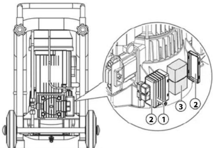
Back view
26. EXTRAORDINARY MAINTENANCE
All activities carried out to ensure use and operation of the appliance, via various intervention types (regulation, valve checks, cleaning of air filters, etc.) executed by the Manufacturer's technicians according to preestablished time intervals and in the instance of faults or wear and tear.

IN THE INSTANCE OF EXTRAORDINARY MAINTENANCE, TECHNICAL ASSISTANCE PROVIDED BY THE MANUFACTURER OR THE AUTHORISED SUPPLIER BE REQUESTED.
27. END OF SERVICE LIFE
When disposing of the appliance, current legislation in force must be considered.
Dispose of the various component materials separately (plastic, copper, iron, etc.).
28. REPLACEMENT PARTS

IN THE INSTANCE OF EXTRAORDINARY MAINTENANCE, TECHNICAL ASSISTANCE PROVIDED BY THE MANUFACTURER OR THE AUTHORISED SUPPLIER MUST BE REQUESTED.
USING UNORIGINAL REPLACEMENT PARTS IS FORBIDDEN.
29. ANOMALIES - CAUSES - SOLUTIONS
The following table displays various scenarios which may occur when using the appliance.

AUTHORISED OPERATORS MUST ONLY CARRY OUT OPERATIONS FOR WHICH THEY ARE QUALIFIED (SEE PARAGRAPH 2) AND WITH THE CONSENT OF THE Y MANAGER (WHERE THE APPLIANCE IS USED IN A ESS CONTEXT).
| ABNORMALITIES CAUSE SOLUTION | ||
| The appli-ance will not start or it stops and will not re-start. | No electrical supply. | ·Check that the “ON-OFF” switch (3) is in the “ON (I)” position.·Check that the electri-cal plug is functioning correctly and is cor-rectly plugged in.·Check that any exten-sions used and the plug are functioning correctly.·Check that the elec-trical main switch is functioning and in the “ON” position. |
| Intervention of thermal reset owing to voltage over-load and/or a short-circuit. | ·Carry out the pro-cedure described in Paragraph 22. | |
| ABNORMALITIES CAUSE SOLUTION | ||
| The appli-ance restarts numerous times even without a utensil. | Leakages from the air pipe, utensil or pneumatic system. | ·Check that the pneumatic system is not damaged.·Check that the air pipe and utensils are intact as well as the connections. |
| The utensil does not emit air. | The tank is not pressurised. | ·Switch on the appli-ance and wait until the tank fills checking the pressure of the relevant gauge. |
| Incorrect regulation of the outlet pressure. | ·Check that the value displayed on the outlet pressure gauge (A) is greater than 0 (zero) bar. | |
| The utensil is damaged. | ·Check that the utensil is intact and effective. | |
| Fall of pres-sure in the air tank. | Leakages in the air pipe, utensil or the pneumatic system. | ·Check that the pneumatic system is not damaged.·Check that the air pipe and utensil are not damaged.·Check that the appli-ance-air pipe and air pipe-utensil connec-tions are correct.·Check that the condensate pump is securely closed (B). |
| Safety valve intervention. | Pressure switch fault. | ·Contact an authorised Supplier. |
| Air loss from the pressure switch when appliance is off. | Unclean or worn return valve. | • Contact an authorised Supplier. |
| The appli-ance vibrates and/or emits lots of noise. | Mechanical fault. | • Contact an authorised Supplier. |
| Frequent start-ups and low perfor-mance. | Unclean air filters. | • Carry out filter clean-ing (see Paragraph 25). |

natural_image
Technical line drawing of a mechanical pressure pump with motor and wheels (no text or symbols)- TECHNICAL SPECIFICATIONS
| W 2,0 kW 1,8 kW | AC33024 | |||||
| Supply voltage/ Frequency | 50 Hz 60 Hz | |||||
| 110 V 230 | V 110 V 230 | V | ||||
| Nominal power 1,8 kW 2,2 kW | ||||||
| Max. operating pressure | 10,5 bar | |||||
| Level of output noise levels A at the work stations (Leg. 2006/42/CE) | 79,6 dB 80,5 dB | |||||
| Driveshaft rotation speed | 1400 rpm 1700 rpm | |||||
| Tank volume 24 lt | ||||||
| Performance (aspirations/yield) | 330/200 l/min 310/180 l/min | |||||
| Temperature/air humidity | +5°C ÷ +40°C / 5% ÷ 95% | |||||
| Total weight 36 Kg | 548×793 mm | |||||
| Dimensions (l×w×h) 477×5 | ||||||
| Motor rotation direction | The compressor can be used in both directions of rotation | |||||
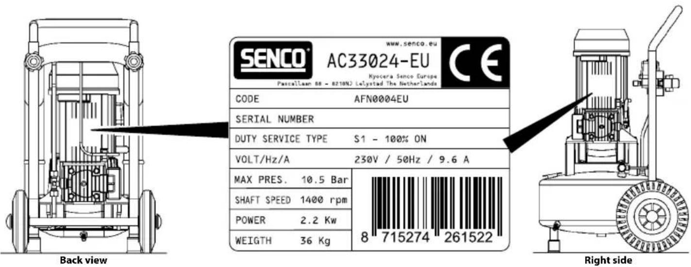
31. CE LABEL
The CE label serves as evidence of the appliance's compliance with essential health and safety requirements as specified by the Machinery Directive 2006/42/CE.
It takes the form of a polyester sticker, with a black thermal transfer mould, which are applied on themotor frame.
INHALT
natural_image
Three sequential line drawings of a person pushing a cart with equipment, no text or symbols present7. VERPACKUNG
natural_image
Technical line drawing of a mechanical device with four wheels and a central component (no text or symbols)natural_image
Top-down diagram of two figures with labeled parts A and B, connected by wires (no text or symbols beyond labels)natural_image
Technical line drawing of a mechanical pressure pump with wheels and internal components (no text or symbols)natural_image
Technical line drawing of a mechanical device with wheels and internal components (no text or symbols)22. RESET DES RÜCKSTELLBAREN THERMOSCHUTZSCHALTERS
natural_image
Technical line drawing of a mechanical device with wheels and internal components (no text or symbols)

natural_image
Technical line drawing of a mechanical pressure pump with wheels and internal components (no text or symbols)- TECHNISCHE DATEN
1. IMPORTANCE DU MANUEL

AVANT D'UTILISER LA MACHINE EN OBJET IL EST OBLIGATOIRE POUR LES OPERATEURS PREPOSES DE LIRE ET COMPRENDRE DANS TOUTES SES PARTIES CE EL D'INSTRUCTIONS.
4. EMPLOI PREVU
DOMAINE D'EMPLOI
Industriel, artisanal et civil.
LIEU D'EMPLOI
ON INTERDIT ABSOLUMENT DE MONTER SUR LA MACHINE.
IL EST ABSOLUMENT INTERDIT DE TRAÎNER LA MACHINE AVEC TOUT MOYEN ET/OU VÉHICULE.
IL EST ABSOLUMENT INTERDIT DE METTRE EN MOUVE-MENT LA MACHINE SUR DES DESCENTES ET/OU PENTES DANGEREUSES.
6. TRANSPORT ET MANUTENTION DE LA MACHINE
natural_image
Three sequential line drawings of a person pushing a cart with a pump, shown in different motion poses (no text or symbols)7. EMBALLAGE
natural_image
Technical line drawing of a mechanical device with four wheels and a central housing (no text or symbols)13. DISPOSITIFS DE SECURITE' ADOPTES
14. SIGNALISATIONS DE SÉCURITÉ
IL EST ABSOLUMENT INTERDIT D'ENLEVER OU ENDOMMAGER LES SIGNAUX DE SECURITÉ APPLIQUES A LA MACHINE.
15. EQUIPEMENT DE PROTECTION INDIVIDUELLE (EPI)

IL EST OBLIGATOIRE D'UTILISER L'EPI PREVU PAR LE CONSTRUCTEUR.
IL EST OBLIGATOIRE QUE LES OPERATEURS AUTORISES UTILISENT L'EPI PREVU PAR LES PRODUCTEURS DES OUTILS UTILISES ET SUR LA BASE DU TYPE D'USINAGE.
ON INTERDIT AUX OPÉRATEURS AUTORISES DE VETIR DES VETEMENTS ET ACCESSOIRES POUVANT RESTER ENCAS-TRÉS DANS LA MACHINE.
natural_image
Illustration of two cartoon figures with labeled parts, connected by wires (no text or symbols present)18. DISPOSITIFS DE COMMANDE
19. CONTRÔLES AVANT LE DÉMARRAGE

AVANT DE RÉALISER L'ALLUMAGE DE LA MACHINE LES OPÉRATEURS AUTORISÉS DOIVENT OBLIGATOIREMENT RÉALISER LES CONTRÔLES INDIQUÉS CI
DESSOUS.
natural_image
Technical line drawing of a mechanical pressure vessel with wheels and internal components (no text or symbols)natural_image
Technical line drawing of a mechanical device with wheels and internal components (no text or symbols)22. RESET INTERVENTION THERMIQUE RÉTABLISSABLE
natural_image
Technical line drawing of a mechanical pressure pump with wheels and internal components (no text or symbols)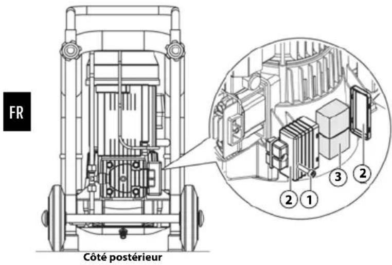

natural_image
Technical line drawing of a mechanical device with wheels and internal components (no text or symbols)- DONNEES TECHNIQUES
4. BEOOGD GEBRUIK
TOEPASSINGSGEBIED
natural_image
Three sequential line drawings of a person pushing a cart with a second cart, illustrating mechanical or operational motion (no text or symbols)7. VERPAKKING
natural_image
Technical line drawing of a mechanical device with four wheels and labeled component (no text or symbols beyond part number 14)natural_image
Top-down diagram of two human figures with labeled parts, connected by wires (no text or symbols present)18. BEDIENINGSAPPARATUUR
De bedieningsapparatuur is weergegeven in Fig.:
19. CONTROLES VOOR INSCHAKELING

DE GEAUTORISEERDE MEDEWERKERS ZIJN VERPLICHT VÖÖR INSCHAKELING VAN DE MACHINE DE ONDERSTAANDE CONTROLES TE VERRICHTEN.
natural_image
Technical line drawing of a mechanical pressure pump with wheels and internal components (no text or symbols)natural_image
Technical line drawing of a mechanical device with wheels and internal components (no text or symbols)22. RESET ZELFHERSTELLENDE THERMISCHE ZEKERING
natural_image
Technical line drawing of a mechanical pressure pump with wheels and internal components (no text or symbols)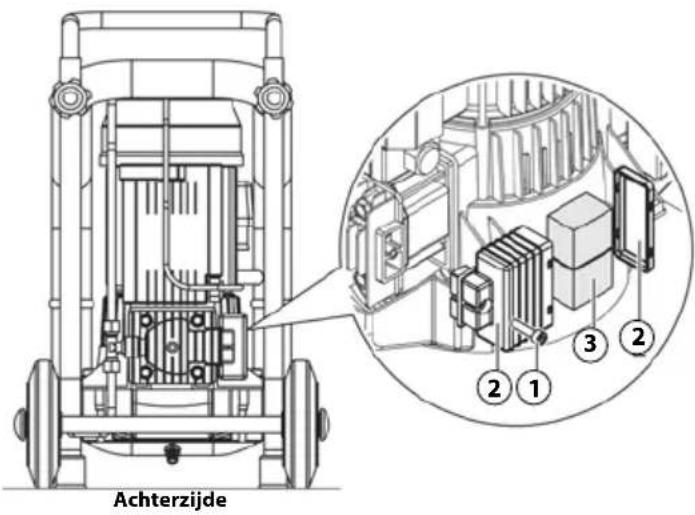
26. BUITENGEWOON ONDERHOUD

natural_image
Technical line drawing of a mechanical device with wheels and internal components (no text or symbols)- TECHNISCHE GEGEVENS
4. USO PREVISTO
CAMPO DE UTILIZAÇÃO
Industrial, artesanal e civil.
LOCAL DE UTILIZAÇÃO
natural_image
Three sequential line drawings of a person pushing a cart with wheels, shown in different motion poses (no text or symbols)7. EMBALAGEM
natural_image
Technical line drawing of a mechanical device with four wheels and a top component (no text or symbols)14. PLACAS DE SEGURANÇA
natural_image
Top-down diagram of a person operating a device with two labeled figures (A and B), no text or symbols present.natural_image
Technical line drawing of a mechanical pressure vessel with wheels and internal components (no text or symbols)natural_image
Technical line drawing of a mechanical device with wheels and internal components (no text or symbols)22. RESET INTERVENÇÃO DO FUSÍVEL TÉRMICO RESTAURÁVEL
natural_image
Technical line drawing of a mechanical pressure pump with wheels and internal components (no text or symbols)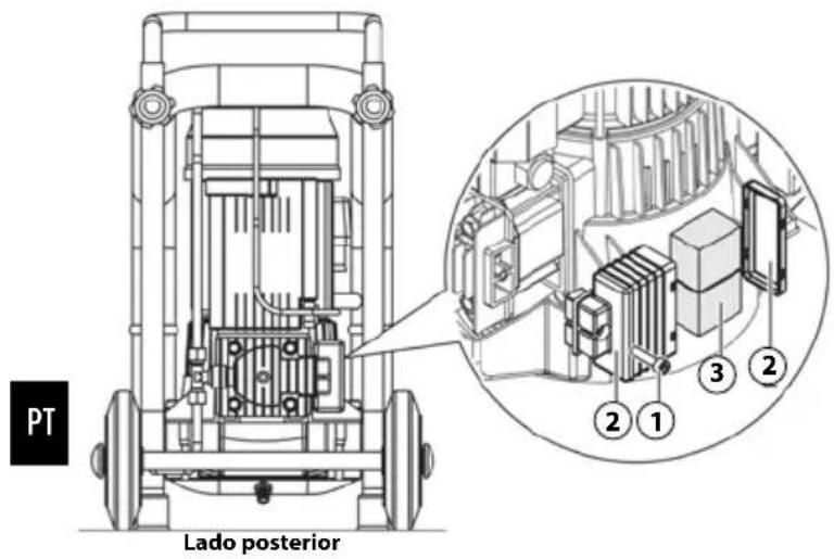

natural_image
Technical line drawing of a mechanical device with wheels and internal components (no text or symbols)- DADOS TÉCNICOS
4. USO PREVISTO
CAMPO DE USO
Industrial, artesanal y civil.
LUGAR DE USO
natural_image
Three sequential line drawings of a person pushing a cart with a pulley, no text or symbols present.7. EMBALAJE
natural_image
Technical line drawing of a mechanical device with four wheels and a central component (no text or symbols)natural_image
Top-down diagram of two figures with labeled parts, connected by wires (no text or symbols present)natural_image
Technical line drawing of a mechanical pressure pump with wheels and internal components (no text or symbols)natural_image
Technical line drawing of a mechanical device with wheels and internal components (no text or symbols)natural_image
Technical line drawing of a mechanical device with wheels and internal components (no text or symbols)
natural_image
Technical line drawing of a mechanical pump or scrubber with visible components and mounting base (no text or symbols)- TECHNICAL SPECIFICATIONS
4. USO PREVISTO
CAMPO D'IMPIEGO
natural_image
Three sequential line drawings of a person pushing a cart with a pulley, no text or symbols present.7. IMBALLO
natural_image
Technical line drawing of a mechanical device with four wheels and a central component (no text or symbols)13. DISPOSITIVI DI SICUREZZA ADOTTATI
14. SEGNALETICA DI SICUREZZA
natural_image
Top-down diagram of two figures with labeled parts, connected by wires (no text or symbols present)18. DISPOSITIVI DI COMANDO
19. CONTROLLI PRIMA DELL'ACCENSIONE

PRIMA DI EFFETTUARE L'ACCENSIONE DELLA MACCHINA GLI OPERATORI AUTORIZZATI DEVONO OBBLIGATORIAMENTE ESEGUIRE I CONTROLLI TATI DI SEGUITO.
natural_image
Technical line drawing of a mechanical pressure vessel with wheels and internal components (no text or symbols)20. ACCENSIONE DELLA MACCHINA

PERICOLO SCOTTATURE PER CONTATTO ACCIDENTALE CON GRUPPO POMPANTE BICILINDRICO E MOTORE ELETTRICO. ATTENZIONE ESISTE UN
RISCHIO RESIDUO (VEDI PARAGRAFO 16).
IL FABBRICANTE DECLINA OGNI RESPONSABILITÀ PER DANNI A PERSONE, ANIMALI E COSE, CAUSATI DALLA INOSSERVANZA DELLE NORME E DELLE AVVERTENZE DESCRITTE NEL PRESENTE MANUALE.
IL FABBRICANTE DECLINA OGNI RESPONSABILITÀ SUL RISULTATO FINALE DELLA LAVORAZIONE IN QUANTO DIPENDENTE ESCLUSIVAMENTE DAL TIPO DI UTENSILE IMPIEGATO E DALLE ABILITÀ PROFESSIONALI DEGLI OPERATORI AUTORIZZATI.
GLI OPERATORI AUTORIZZATI POSSONO ACCENDERE LA MACCHINA SOLTANTO DOPO AVER OBBLIGATORIAMENTE ESEGUITO I CONTROLLI DESCRITTI NEL PARAGRAFO 19.
PRIMA DI UTILIZZARE LA MACCHINA IN OGGETTO È OBBLIGATORIO CHE GLI OPERATORI AUTORIZZATI LEGGANO E COMPRENDANO IN TUTTE LE SUE PARTI IL PRESENTE MANUALE.
natural_image
Technical line drawing of a mechanical device with wheels and internal components (no text or symbols)22. RESET INTERVENTO TERMICO RIPRISTINABILE
natural_image
Technical line drawing of a mechanical device with wheels and internal components (no text or symbols)
26. MANUTENZIONE STRAORDINARIA

natural_image
Technical line drawing of a mechanical device with wheels and internal components (no text or symbols)- TECHNICAL SPECIFICATIONS
natural_image
Three sequential line drawings of a person pushing a cart with equipment, shown in different motion poses (no text or symbols)7. ΣΥΣΚΕΥΑΣΙΑ
natural_image
Technical line drawing of a mechanical device with four wheels and a central housing (no text or symbols)16. KINΔΥΝΟΙ ΠΟΥ ΠΑΡΑΜΕΝΟΥΝ
GR
natural_image
Top-down diagram of two figures with labeled parts, connected by wires (no text or symbols present)natural_image
Technical line drawing of a mechanical pressure pump with wheels and internal components (no text or symbols)natural_image
Technical line drawing of a mechanical device with wheels and internal components (no text or symbols)natural_image
Technical line drawing of a mechanical device with wheels and internal components (no text or symbols)

natural_image
Technical line drawing of a mechanical device with wheels and internal components (no text or symbols)4. AVSEDD ANVÄNDNING
ANVÄNDNINGSOMRÅDE
DET ÄR ABSOLT FÖRBJUDET ATT FÖRFLYTTA MASKINEN FÖR HAND I SLUTTNINGAR/STIGNINGAR MED FARLIG LUTNING.
6. TRANSPORT OCH FÖRFLYTTNING AV MASKINEN
natural_image
Three sequential line drawings of a person pushing a cart with a pulley, no text or symbols present.7. FÖRPACKNING
natural_image
Technical line drawing of a mechanical device with four wheels and a central housing (no text or symbols)13. TILLÄMPADE SKYDDSANORDNINGAR
14. SÄKERHETSSKYLTAR
natural_image
Top-down diagram of two figures with labeled parts, connected by wires (no text or symbols present)18. STYRENHETER
19. KONTROLLER FÖRE PÅSLAGNING

FÖRE PÅSLAGNING AV MASKINEN MÅSTE DE AUKTORISERADE OPERATÖRERNA OBLIGATORISKT UTFÖRA FÖLJANDE KONTROLLER.
natural_image
Technical line drawing of a mechanical pressure pump with wheels and internal components (no text or symbols)natural_image
Technical line drawing of a mechanical device with wheels and internal components (no text or symbols)22. RESET AV ÅTERSTÄLLNINGSBAR TERMISK BRYTARE
natural_image
Technical line drawing of a mechanical device with wheels and a central motor (no text or symbols)
Baksida
26. EXTRAORDINÄRT UNDERHÅLL

natural_image
Technical line drawing of a mechanical device with wheels and internal components (no text or symbols)- TEKNISKA DATA
4. BEREGNET BRUK
VIRKEFELT
DET ER FORBUDT Å KLATRE OPP PÅ APPARATET.
DET ER FORBUDT Å SLEPE APPARATET MED ENHVER TYPE TRANSPORTMIDDEL ELLER KJ∅RET∅Y.
6. TRANSPORT OG FLYTTING AV KOMPRESSOREN
natural_image
Three sequential line drawings of a person pushing a cart with a pulley, no text or symbols present.7. EMBALLASJE
natural_image
Technical line drawing of a mechanical device with four wheels and a central component (no text or symbols)13. UTSTYR SOM ER MONTERT FOR SIKKER BRUK AV KOMPRESSOREN
14. SIKKERHETSMERKER
natural_image
Top-down diagram of a person using a handheld device to interact with two seated figures labeled A and B (no text or symbols present)18. LUFTTRYKKSREGULATOR, TRYKKBRYTER/ PRESSOSTAT, MANOMETRE OG KUPLING
19. SJEKK F∅R OPPSTART

F∅R APPARATET SLÅS PÅ, MÅBRUKER UTF∅RE F∅LGENDE KONTROLLER.
natural_image
Technical line drawing of a mechanical pressure pump with wheels and internal components (no text or symbols)natural_image
Technical line drawing of a mechanical device with wheels and internal components (no text or symbols)22. NULLSTILLING - TERMISK GJENOPPRETTING
Hvis det er en overbelastning og/ eller en kortslutning i den elektriske motoren, vil den termiske sikringen utløse og stoppe den elektriske motoren. For tilbakestilling av termisk sikring, følg disse trinnene:
25. STANDARDVEDLIKEHOLD
natural_image
Technical line drawing of a mechanical pressure pump with wheels and internal components (no text or symbols)
26. EKSTRAORDINÄERT VEDLIKEHOLD

natural_image
Technical line drawing of a mechanical device with wheels and a central motor (no text or symbols)- TEKNISKE SPESIFIKASJONER
4. KÄYTTÖKOHDE
KÄYTTÖALUE
natural_image
Three line drawings of a person pushing a cart with equipment, shown in different motion poses (no text or symbols)7. PAKKAUS
natural_image
Technical line drawing of a mechanical device with four wheels and labeled component (no text or symbols beyond part number 14)13. TURVALAITTEET
14. TURVAMERKINNÄT
natural_image
Top-down diagram of two figures with labeled parts A and B, connected by wires (no text or symbols beyond labels)18. OHJAUSLAITTEET
Näkyvät KUNASSA:
19. TARKASTUKSET ENNEN KYTKEMISTÄ PÄÄLLE

ENNEN KONEEN KÄYNNISTÄMISTÄ KÄYTTÄJÄN ON SUORITETTAVA SEURAAVAT TARKASTUKSET.
natural_image
Technical line drawing of a mechanical pressure pump with wheels and internal components (no text or symbols)natural_image
Technical line drawing of a mechanical device with wheels and internal components (no text or symbols)22. PALAUTETTAVAN LÄMPÖKYTKIMEN LAUKEAMISEN PALAUTUS
natural_image
Technical line drawing of a mechanical device with wheels and internal components (no text or symbols)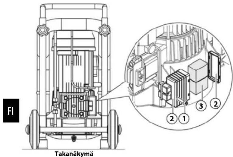
26. LISÄHUOLTO

natural_image
Technical line drawing of a mechanical device with wheels and internal components (no text or symbols)- TEKNISET TIEDOT
4. EGNET BRUG
ANVENDELSESOMRÅDE
Industrial, artesanal e civil.
ANVENDELSESTED

NB!
MASKINENW SKAL VÄRE UDEN FOR B∅RNS RÄEKKEVIDDE.
EGNET BRUG
DET ER STRENGT FORBUDT AT ANVENDE MASKINEN TIL AT TRANSPORTERE OG/ELLER L∅FTE PERSONER, DYR OG TING.
DET ER STRENGT FORBUDT AT GÅ UD PÅ MASKINEN.
DET ER STRENGT FORBUDT AT SLÆBE MASKINEN MED ALLE MIDLER OG/ELLER K∅RET∅J.
DET ER STRENGT FORBUDT AT FLYTTE MASKINEN MANUEL T PÅ NEDGANGE OG/ELLER UDGANGE MED FARLIGE HÆLD- NINGER.
6. TRANSPORT OG FLYTNING AF MASKINEN
natural_image
Three sequential line drawings of a person pushing a cart with a device, shown in different motion poses (no text or symbols)7. EMBALLAGE
natural_image
Technical line drawing of a mechanical device with four wheels and a central component (no text or symbols)13. INSTALLERET SIKKERHEDSUDSTYR
14. SIKKERHEDSSIGNALER
natural_image
Illustration of two cartoon pandas with labeled positions A and B, connected by a cable (no text or symbols beyond labels)18. BETJENINGSUDSTYR
19. KONTROLLER, INDEN MASKINEN TÄENDES

INDEN MASKINEN TÄENDES, SKAL DE AUTORISEREDE BRUGERE FORETAGE KONTROLLERNE ANFÖRT NEDENFOR.
natural_image
Technical line drawing of a mechanical pressure pump with wheels and motor (no text or symbols)natural_image
Technical line drawing of a mechanical pressure pump with wheels and internal components (no text or symbols)22. NULSTIL INDGREB FRA INDSTILLELIGT VARMEANLÆG
23. N∅DSTOP
Maskinen kan nødstoppes ved at stille afbryderen "ON-OFF" på "OFF (0)" (3).
natural_image
Technical line drawing of a mechanical pressure pump with wheels and internal components (no text or symbols)
Bagside
26. EKSTRAORDINÆR VEDLIGEHOLDELSE
natural_image
Technical line drawing of a mechanical pressure pump with wheels and internal components (no text or symbols)- TEKNISKE OPLYSNINGER
natural_image
Three sequential line drawings of a person pushing a cart with equipment, shown in different motion poses (no text or symbols)7. УПАКОВКА
natural_image
Technical line drawing of a mechanical device with wheels and components (no text or symbols)natural_image
Top-down diagram of two figures with labeled parts, connected by wires (no text or symbols present)natural_image
Technical line drawing of a mechanical pressure vessel with wheels and internal components (no text or symbols)natural_image
Technical line drawing of a mechanical device with wheels and internal components (no text or symbols)22. СБРОС СРАБАТЫВАНИЯ ТЕПЛОВОГО ПРЕДОХРАНИТЕЛЯ
natural_image
Technical line drawing of a mechanical device with wheels and internal components (no text or symbols)
natural_image
Technical line drawing of a mechanical device with wheels and internal components (no text or symbols)- ТЕХНИЧЕСКИЕ ДАННЫЕ
VOLITATUD TÖÖTAJAD TOHIVAD MASINAGA TEHA ÜKSNES NEID TOIMINGUID, MIS ON NENDE PÄDEVUSES. ENNE MASINAGA MIS TAHES
TOIMINGU TEGEMIST PEAVAD VOLITATUD TÖÖTAJAD VEENDUMA, ET NEIL ON TÄIELIKULT PSÜHHOLOOGILISED JA FÜÜSILISED OMADUSED, MIS TAGAVAD IGAS OLUKORRAS TURVALISUSE.
4. NÕUETEKOHANE KASUTUS
KASUTUSVALDKOND
natural_image
Three sequential line drawings of a person pushing a cart with equipment, shown in different motion poses (no text or symbols)7. PAKEND
natural_image
Technical line drawing of a mechanical device with four wheels and a central housing (no text or symbols)13. RAKENDATUD TURVAMEETMED
14. OHUTUSMÄRGISTUS
natural_image
Top-down diagram of two cartoon characters with labeled parts, connected by wires (no text or symbols present)18. JUHTIMISSEADMED
19. ENNE SISSELÜLITAMIST TEHTAVAD KONTROLLID

ENNE MASINA SISSELÜLITAMIST PEAVAD VOLITATUD TÖÖTAJAD TINGIMATA TEGEMA JÄRGMIST.
natural_image
Technical line drawing of a mechanical pressure pump with wheels and internal components (no text or symbols)natural_image
Technical line drawing of a mechanical device with wheels and internal components (no text or symbols)22. ENNISTATAVA TERMOKAITSME LÄHTESTAMINE
natural_image
Technical line drawing of a mechanical pressure pump with wheels and control panel (no text or symbols)
Tagumine külg
26. ERIKORRALINE HOOLDUS

natural_image
Technical line drawing of a mechanical pressure pump with wheels and internal components (no text or symbols)- TEHNILISED ANDMED
4. NAUDOJIMO PASKIRTIS
VEIKIMO SRITIS
natural_image
Three sequential illustrations of a person pushing a cart with equipment, shown in different motion poses (no text or symbols)7. PAKAVIMAS
natural_image
Technical line drawing of a mechanical device with wheels and components (no text or symbols)13. PRIIMTI SAUGOS JRENGINIAI
14. SAUGOS ŽENKLAI
natural_image
Top-down diagram of two figures with labeled parts, connected by wires (no text or symbols present)18. KOMANDU İRENGINIAI
19. PATIKRINIMAI PRIEŠ PALEIDŽIANT [RENGINI]
![Senco AC33024 - PATIKRINIMAI PRIEŠ PALEIDŽIANT [RENGINI] - 1](/content/2026/04/588802/images/36770efb2c6f47c6d1a06bf2989552974ec9f7172116b8ac1bf3b9f428358542.jpg)
PRIEŠ PRADEDANT EKPLOATUOTI PRIETAISĄ, IGALIOTI OPERATORIAI TURI ATLIKTI ŠIUOS PATIKRINIMUS.
natural_image
Technical line drawing of a mechanical pressure pump or scrubber with visible components and mounting base (no text or labels)natural_image
Technical line drawing of a mechanical device with wheels and internal components (no text or symbols)LT
22. NUSTATYKITE INTERVENCIJA - ATNAUJINKITE ŠILUMA
natural_image
Technical line drawing of a mechanical device with wheels and internal components (no text or symbols)
Galinis vaizdas
26. YPATINGA PRIEŽIŪRA

natural_image
Technical line drawing of a mechanical pressure pump with wheels and internal components (no text or symbols)- TECHNINÉS SPECIFIKACIJOS
4. PAREDZETA IZMANTOŠANA
IZMANTOŠANAS JOMA
natural_image
Three line drawings of a person pushing a cart with an open box, shown in different motion poses (no text or symbols)7. IEPAKOJUMS
natural_image
Technical line drawing of a mechanical device with four wheels and a central housing (no text or symbols)13. UZSTĀDĪTĀS DROŠĪBAS IERĪCES
14. DROŠĪBAS ZĪMES
natural_image
Top-down diagram of two cartoon characters interacting with a device, labeled A and B (no text or symbols on the figures themselves)18. VADİBAS IERİCES
19. PIRMS IESLĖGŠANAS VEICAMĀS PĀRBAUDES

PIRMS IEKÄRTAS IESLËGŠANAS KVALIFICËTIEM OPERATORIEM OBLIGÄTI JÄVEIC TÄLÄK APRAKSTITÄS PÄRBAUDES.
natural_image
Technical line drawing of a mechanical pressure pump with wheels and internal components (no text or symbols)natural_image
Technical line drawing of a mechanical device with wheels and internal components (no text or symbols)22. NOSTRĀDĀJUŠA TERMOSLĒDŽA ATKĀRTOTA AKTIVIZĒŠANA
natural_image
Technical line drawing of a mechanical device with wheels and a motor (no text or symbols)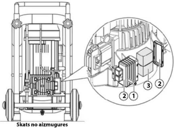
26. PAPILDU APKOPE

natural_image
Technical line drawing of a mechanical device with wheels and internal components (no text or symbols)- TEHNISKÄ SPECIFIKÄCIJA
KONSERWATOR MECHANICZNY / PNEU-
4. PRZEWIDZIANE ZASTOSOWANIE
OBSZAR ZASTOSOWANIA
natural_image
Three sequential line drawings of a person pushing a cart with a pulley, no text or symbols present.7. OPAKOWANIE
natural_image
Technical line drawing of a mechanical device with four wheels and a central housing (no text or symbols)13. ASTOSOWANE URZĄDZENIA BEZPIECZEŃSTWA
14. SYGNALIZACJA BEZPIECZEŃSTWA
natural_image
Top-down diagram of two figures with labeled parts, connected by wires (no text or symbols present)18. URZĄDZENIA STERUJĄCE
19. KONTROLE DO WYKONANIA PRZEZ WŁĄCZENIEM

PRZED WŁĄCZENIEM MASZYNY UPOWAŻNIENI OPERATOROWIE MUSZĄ OBOWIĄZKOWO WYKONAĆ KONTROLE WSKAZANE PONIŻEJ.
natural_image
Technical line drawing of a mechanical pressure vessel with wheels and internal components (no text or symbols)natural_image
Technical line drawing of a mechanical device with wheels and internal components (no text or symbols)22. RESET INTERWENCJI WYŁĄCZNIKA TERMICZNEGO RESETOWANEGO
natural_image
Technical line drawing of a mechanical device with wheels and internal components (no text or symbols)
26. KONSERWACJA NADZWYCZAJNA

natural_image
Technical line drawing of a mechanical device with wheels and internal components (no text or symbols)- DANE TECHNICZNE
1. DŮLEŽITOST TOHOTO MANUÁLU

PŘED POUŽITÍM PŘÍSTROJE SI MUSÍ POVĚŘENÍ UŽIVATELÉ PŘEČÍST CELÝ PŘILOŽENÝ NÁVOD K OBSLUZE A POROZUMĚT MU.
4. ZAMÝŠLENÉ POUŽITÍ
OBLAST PROVOZU
natural_image
Three sequential line drawings of a person pushing a cart with equipment, shown in different motion poses (no text or symbols)7. BALENÍ
natural_image
Technical line drawing of a mechanical device with four wheels and a labeled component (no text or symbols beyond the number 14)13. POUŽITÁ BEZPEČNOSTNÍ ZAŘÍZENÍ
14. BEZPEČNOSTNÍ ZNAČKY
natural_image
Top-down diagram of two figures with labeled parts, connected by wires (no text or symbols present)18. OVLÁDACÍ ZAŘÍZENÍ
19. KONTROLY PŘED SPUŠTĚNÍM

PŘED SPUŠTĚNÍM PŘÍSTROJE MUSÍ POVĚŘENÁ OBSLUHA PROVÉST NÁSLEDUJÍCÍ KONTROLY.
natural_image
Technical line drawing of a mechanical pressure pump with wheels and internal components (no text or symbols)natural_image
Technical line drawing of a mechanical device with wheels and internal components (no text or symbols)CZ
natural_image
Technical line drawing of a mechanical device with wheels and a motor (no text or symbols)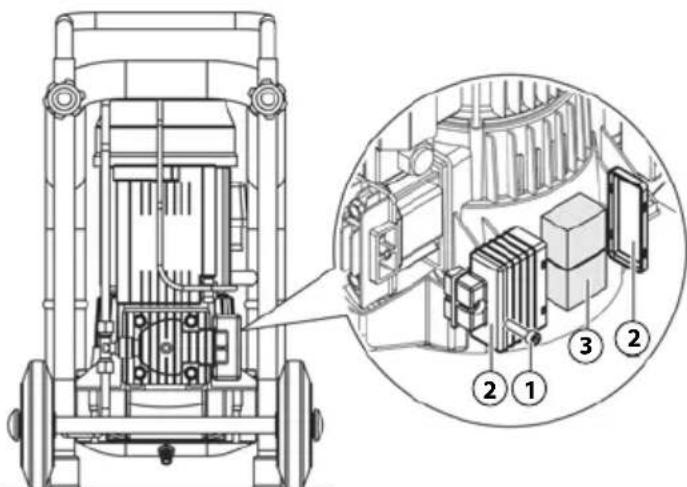

natural_image
Technical line drawing of a mechanical pressure pump with wheels and internal components (no text or symbols)- TECHNICKÉ SPECIFIKACE
4. ÚČEL POUŽITIA
OBLAST PREVÁDZKY
Priemyselná, remeselná a civilná.
MIESTO PREVÁDZKY
natural_image
Three line drawings of a person pushing a cart with a pump, shown in different motion poses (no text or symbols)7. BALENIE
natural_image
Technical line drawing of a mechanical device with four wheels and a central component (no text or symbols)13. PRIJATÉ BEZPEČNOSTNÉ ZARIADENIA
14. BEZPEČNOSTNÉ ZNAČKY
15. OSOBNÉ OCHRANNÉ PROSTRIEDKY (OOP)

MUSÍ SA POUŽÍVAŤ OSOBNÉ OCHRANNÉ PROSTRIED-KY VYDÁVANÉ VÝROBCOM.
AUTORIZOVANÍ OPERÁTORI MUSIA NOSIŤ OSOBNÉ OCHRANNÉ PROSTRIEDKY VYDÁVANÉ VÝROBCAMI ZARIADENÍ NA ZÁKLADE PRÁCE, KTORÁ SA MÁ VYKONAT.
AUTORIZOVANÍ OPERÁTORI NESMÚ NOSIŤ ODEVY A/ALEBO DOPLNKY, KTORÉ BY SA MOHLI ZACHYTIŤ V ZARIADENÍ.
natural_image
Top-down diagram of two figures interacting with a device, labeled A and B (no text or symbols on the figures themselves)18. PRÍKAZOVÉ ZARIADENIA
19. KONTROLY PRED ŠTARTOVANÍM

PRED SPUSTENÍM ZARIADENIA MUSIA AUTORIZOVANÍ OPERÁTORI VYKONAT NÁSLEDUJÚCE KONTROLY.
natural_image
Technical line drawing of a mechanical pressure vessel with wheels and internal components (no text or symbols)natural_image
Technical line drawing of a mechanical device with wheels and internal components (no text or symbols)22. RESETOVANÝ ZÁSAH - TEPELNÉ OBNOVENIE
natural_image
Technical line drawing of a mechanical device with wheels and a motor (no text or symbols)
natural_image
Technical line drawing of a mechanical device with wheels and internal components (no text or symbols)- TECHNICKÉ ŠPECIFIKÁCIE
4. RENDELTETÉS SZERINTI HASZNÁLAT
MÜKÖDÉSI TERÜLET
natural_image
Three sequential line drawings of a person pushing a cart with equipment, shown in different motion poses (no text or symbols)7. CSOMAGOLÁS
natural_image
Technical line drawing of a mechanical device with four wheels and a labeled component (no text or symbols present)13. BIZTONSÁGI SZERKEZETEK
14. BIZTONSÁGI SZIMBÓLUMOK
natural_image
Top-down diagram of two figures with labeled parts, connected by wires (no text or symbols present)18. VEZÉRLŐ ESZKÖZÖK
natural_image
Technical line drawing of a mechanical pressure vessel with wheels and internal components (no text or symbols)natural_image
Technical line drawing of a mechanical device with wheels and internal components (no text or symbols)natural_image
Technical line drawing of a mechanical device with wheels and internal components (no text or symbols)

natural_image
Technical line drawing of a mechanical device with wheels and internal components (no text or symbols)- MÜSZAKI ADATOK
4. NAMENJENA UPORABA
PODROČJE DELOVANJA
Industrijska, obrtna in civilna.
KRAJ DELOVANJA
UPORABA STROJA JE NAJBOLJ PREPOVEDANA NA OBMOČ-JIH, KI VSEBUJEJO TRDE DELCE.
NEVARNOST OPEKLIN PRI NESREČNEM STIKU S DVOJNIM CILINDRIČNIM ČRPALNIM SISTEMOM IN ELEKTRIČNIM MOTORJEM. OPOZORILO - OSTALO TVEGANJE (GLEJ ODSTAVEK 16).
STROJ MORAMO UPORABLJATI V SKLADU Z ZAKONOD-AJO, KI UREJA EMISIJE (ŠUM) V VELJAVNOSTI V DRŽAVI UPORABE.
MED UPORABO ZAGOTOVITE, DA NEPOOBLAŠČENE OSEBE NE PRIDEJO V BLIŽINO NAPRAVE.
APARAT MORA BITI IZVEN DOSEGA OTROK.
NEPRAVILNA UPORABA NAPRAVE ALI UPORABA, KI SE RAZLIKUJE OD NAVEDENEGA V OdstAVKU 4, PREPOVEDANA.
UPORABA NEPRIMERNIH ZRAČNIH CEVI (RAZŠIRITVE), PRIKLJUČKOV IN PRIPOMOČK ALI TISTIH, KI NISO V SKLADU S TRENUTNO ZAKONODAJO, JE V celoti prepovedana.
PREPOVEDANO JE DVIGANJE NAPRAVE Z ŽERJAVI
PREPOVEDANA JE USMERITEV STISKANIH ZRAČNIH CURKOV V OSEBE ALI ŽIVALI
PREPOVEDANA JE UPORABA NAPRAVE ZA PREMIKANJE IN / ALI DVIGANJE OSEB, ŽIVALI ALI PREDMETOV.
PREPOVEDANA JE NAMESTITEV NAPRAVE.
PREPOVEDANO JE VLEČI NAPRAVO S KAKRŠNO KOLI VRSTO VOZILA.
PREPOVEDANO JE, DA ROČNO PREMIKATE NAPRAVO NAVZGOR IN / ALI DOL, KJER SO NEVARNI NAKLONI.
6. PREVOZ IN PREMIK NAPRAVE
natural_image
Line drawing showing three sequential scenarios of a person pushing a cart with an open box, no text or symbols present.7. PAKIRANJE
natural_image
Technical line drawing of a mechanical device with four wheels and a top component (no text or symbols)13. SPREJETE VARNOSTNE NAPRAVE
14. VARNOSTNI ZNAKI
Uporabljeni varnostni znaki imajo lepljivo nalepko na zunanji strani naprave.
Definicije znakov:
① Opozorilo - električna energija.
② Opozorilo - samodejni zagon.
③ Opozorilo - visoka temperatura.
④ Navodila je treba prebrati.
⑤ Napajanje mora biti izključeno.
⑥ Zaščitite svoj sluh.
⑦ Zajamčena raven zvočne moči.

VARNOSTNI ZNAK MORA BITI ČIST, DA BODO VIDEN.
VARNOSTNI ZNAKI, KI SO POŠKODOVANI MORAJO BITI ZAMENJANI; PROSITE ZA NADOMESTILO PROIZVAJALCA ALI POOBLAŠČENEGA DOBAVITELJA.
ODSTRANJEVANJE IN / ALI POŠKODOVANJE VARNOSTNEGA NAPISA, PRIPOROČENEGA NA NAPRAVI, JE STROGO PREPOVEDANO.
15. OSEBNA ZAŠČITNA OPREMA (PPI)

OBVEZNA JE UPORABA OSEBNE ZAŠČITNE OPREME, KI JIH JE IZDELAL PROIZVAJALEC.
POOBLAŠČENI OPERATERJI MORAJO NOSITI OSEBNO ZAŠČITNO OPREMO, KI JO IZDAJO PROIZVAJALCI, ZAPOS-LENIH NA PODLAGI DELA, KI GA JE TREBA IZVESTI.
POOBLAŠČENI OPERATERJI NE SMEJO NOSITI OBLAČIL IN / ALI DODATNE OPREME, KI BI LAHKO POSTALI UJETI V NAPRAVI.
natural_image
Top-down diagram of two cartoon figures with labeled parts, connected by wires (no text or symbols present)18. UKAZNE NAPRAVE
Ukazne naprave so:
19. PREVERJANJA PRED ZAČETKOM

PRED ZAČETJEM NAPRAVE MORAJO POOBLAŠČENI OPERATERJI IZVEDITI NASLEDNJE PREVERJANJE.
natural_image
Technical line drawing of a mechanical pressure pump with wheels and internal components (no text or symbols)1) Napravo priključite na napajanje (1), tako da jo priključite.
2) Napravo vklopite s stikalom "ON-OFF" (3), tako da je v položaju "ON (I)" (naprava deluje, dokler ne doseže največjega delovnega tlaka 10 barov, nato pa se preklopi samodejno izklopi.
3) Izhodni tlak regulirajte z ustreznim regulatorjem (4) glede na uporabljeno posodo in vrsto dela. Nadzirajte tlak, prikazan z ustreznim merilnikom (6).

NE ODVIJAJTE MERILNIKA TLAKA V CELOTI (4), ALI TVEGATE, DA BI POŠKODOVALI MEMEBRANO.
natural_image
Technical line drawing of a mechanical device with wheels and internal components (no text or symbols)22. PONASTAVI INTERVENCIJO - TERMO OBNAVLJA
natural_image
Technical line drawing of a mechanical pressure pump with wheels and internal components (no text or symbols)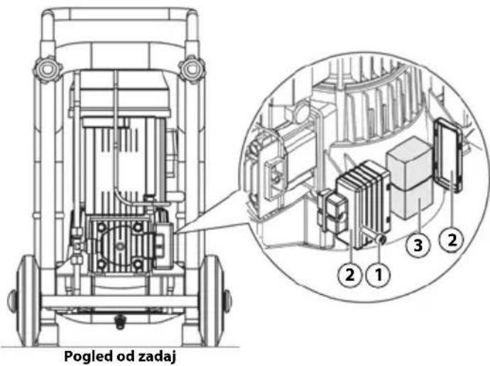
26. IZREDNO VZDRŽEVANJE

natural_image
Technical line drawing of a mechanical pressure pump with wheels and internal components (no text or symbols)- TEHNIČNE SPECIFIKACIJE
4. DESTINATIE
DOMENIU DE UTILIZARE
natural_image
Three line drawings of a person pushing a cart with a second image showing a smaller cart (no text or symbols)7. ÎMPACHETARE
natural_image
Technical line drawing of a mechanical device with wheels and a central component (no text or symbols)13. DISPOZITIVE DE SIGURANTĂ ADOPTATE
14. SIMBOLURI DE SIGURANTĂ
natural_image
Illustration of two cartoon characters interacting with a device, labeled A and B (no text or symbols on the figures themselves)18. DISPOZITIVE DE COMANDĂ
19. VERIFICĂRI ÎNAINTE DE PORNIRE

ÎNAINTE DE A PORNI ECHIPAMENTUL, OPERATORII AUTORIZAȚI TREBUIE SĂ EFECTUEZE URMĂTOARELE VERIFICĂRI.
natural_image
Technical line drawing of a mechanical pressure pump with wheels and internal components (no text or symbols)natural_image
Technical line drawing of a mechanical pressure pump with wheels and internal components (no text or symbols)22. INTERVENTIE DE RESETARE - RESTABILIRE TERMICĂ
natural_image
Technical line drawing of a mechanical device with wheels and internal components (no text or symbols)
Vedere din spate
26. MENTENANTĂ EXCEPTIONALĂ

natural_image
Technical line drawing of a mechanical pressure pump with wheels and internal components (no text or symbols)- DATE TEHNICE
4. ПРЕДНАЗНАЧЕНИЕ
ОБСЕГ НА РАБОТА
natural_image
Three sequential line drawings of a person pushing a cart with a second cart, illustrating mechanical or electrical handling (no text or symbols)7. ОПАКОВКА
natural_image
Technical line drawing of a mechanical device with four wheels and a central component (no text or symbols)13. ПРИЕТИ БЕЗОПАСНИ УСТРОЙСТВА
natural_image
Top-down diagram of two figures with labeled parts, connected by wires (no text or symbols present)18. КОМАНДНИ УСТРОЙСТВА
19. ПРЕДВАРИТЕЛНИ ПРОВЕРКИ

natural_image
Technical line drawing of a mechanical pressure pump with wheels and internal components (no text or symbols)natural_image
Technical line drawing of a mechanical device with wheels and internal components (no text or symbols)22. НУЛИРАНЕ НА ИНТЕРВЕНЦИЯТА - ТЕРМИЧНО ВЪЗСТАНОВЯВАНЕ
natural_image
Technical line drawing of a mechanical device with wheels and internal components (no text or symbols)

natural_image
Technical line drawing of a mechanical device with wheels and internal components (no text or symbols)3. DURUM "CİHAZ KAPALI"
4. AMAÇLANAN KULLANIM
ÇALIŞMA ALANI
natural_image
Three sequential line drawings of a person pushing a cart with equipment, shown in different motion poses (no text or symbols)7. PAKETLEME
natural_image
Technical line drawing of a mechanical device with four wheels and a central housing (no text or symbols)13. KULLANILAN GÜVENLİK CİHAZLARI
natural_image
Top-down diagram of two figures with labeled parts, connected by wires (no text or symbols present)18. KOMUT CİHAZLARI
19. BAŞLATMA ÖNCESİ KONTROLLER

natural_image
Technical line drawing of a mechanical pressure pump with wheels and internal components (no text or symbols)natural_image
Technical line drawing of a mechanical device with wheels and internal components (no text or symbols)
IF, AFTER CARRYING OUT THERMAL RESTORE, THE APPLIANCE DOES NOT RESTART, THE QUALIFIED OPERATOR MUST REQUEST THE INTERVENTION OF TENANCE PERSONS AND/OR THE AUTHORISED LIER.
22. SIFIRLAMA MÜDAHALESİ – TERMAL GERİ YÜKLEME
natural_image
Technical line drawing of a mechanical device with wheels and a motor (no text or symbols)
26. OLAĞANDIŞI BAKIM

natural_image
Technical line drawing of a mechanical pressure pump with motor and wheels (no text or symbols)- TEKNİK ÖZELLİKLER
1. Senco Professional End User Warranty Policy
Considering the following constraints Senco underwrites the reliability and the quality of its supplied authorised Senco branded products.
1.1 Senco warrants to the end user that the following products will be free from defects in construction, assembly and material for the warranty period specified below.
| Product Warranty period | |
| Senco® XP Series-Red Cap, pneumatic tools Five years | |
| Senco Pro Series, pneumatic tools | One year |
| Senco Semi-Pro Series, pneumatic tools | One year |
| Senco Black Label Series, Pneumatic tools | One year |
| Senco DuraSpin® Series, electric and battery tools One year | |
| Senco Cordless battery tools | Two years |
| Senco batteries and chargers for tools | One year |
| Senco gas tools | Two years |
| Senco Reconditioned Products | One year |
| Senco other tools | One year |
| Senco Compressors | One year |
1.2 The warranty period starts on the day the end user purchases the product and/or 1 year after the tool has been deleted from the product line, which ever date comes first.
1.3 To claim warranty the end user needs to send the defective products or their parts, including the serial number and the original and dated sales receipt or proof of purchase from the original retailer or dealer, freight prepaid to the original retailer or dealer.
1.4 Senco is not obliged to do any repairs or replacements on any products or their parts on site.
1.5 During the warranty period Senco or its distributors will repair or replace defective products or their parts, exclusively or mainly as a result of an imperfection in construction, assembly or material, at Senco's option and expense, subject to the constraints of this warranty policy.
1.6 The repair or replacement of products or their parts under warranty, does in no case lead to prolongation of the warranty period. For every replacement product or part, the remaining original warranty period of the replaced product or part is applicable.
1.7 Senco will become the owner of the products or parts that have been replaced by Senco or its distributors as a result of being compliant to Senco's warranty, without being obligated any compensation in this matter.
1.8 Excluded from the warranty are:
- normal wear and tear parts, for example rubber o-rings, seals, driver blades, piston stops, piston/driver assemblies, isolators, drive belts, air filters and fuel systems, bits;
- any imperfection that is a result of or has evolved from the fact that there has not been used clean, dry regulated compressed air and/or the air pressure applied has exceeded the maximum indicated on the tool casting (pneumatic tools);
- any imperfection that is a result of or has evolved from normal wear, misapplication, abuse/misuse, improper modifications or storage, shipping/transport, accidents, neglect, operation at other than recommended speeds or voltage (electric units only);
- any imperfection that is a result of or has evolved from explosions, fires and natural disasters, like hurricanes, floods and earthquakes;
- Any imperfection that is a result of or has evolved from not following operating instructions, specifications and / or maintenance schedules. Read the Operator Manual for use, specifications and maintenance instructions;
- Any imperfection that is caused by repairs, modifications to the product or attempts to do so by the end user or any third party;
- Labour charges or loss or damage resulting from improper operation, maintenance or repairs are not covered by this warranty
- Any warranty claims that have been received after the warranty period, as specified in this end user warranty, has expired.
1.9 Additional costs like shipping/transport, special packaging requirements and costs of travel and accommodation, are at the end users expense.
1.10 If a complaint is unfounded, all costs incurred thereby, including handling, inspection, shipping and administrative costs on the side of Senco or its distributors, will be charged to the end user.
1.11 After expiration of the warranty period, all costs for repair or replacement, including handling, inspection, shipping and administrative costs will be charged to the end user.
1.12 Notwithstanding legal limitation periods, the limitation of all claims and appeals against Senco and third parties involved by Senco for the implementation of the agreement is one year.
1.13 If Senco fails to meet this agreement, it will not discharge the end user from the obligations arising under this or any other contract.
1.14 When the warranty terms can not be met, due to for example import or export prohibitions, strikes or other unforeseen circumstances, the warranty period will be extended accordingly.
1.15 Senco's liability is limited to the warranty. Senco is not liable for damage caused by the functioning or non-functioning of the products as delivered, repaired or modified by Senco or its distributors, including but not limited to, production losses, profit losses, reduced working range, commercial losses or consequential damages or indirect damages whatsoever.