2000i - Generator AL-KO - Free user manual and instructions
Find the device manual for free 2000i AL-KO in PDF.

| Product type | Generator |
| Brand | AL-KO |
| Model | 2000i |
| AC output voltage | 230 V |
| DC output voltage | 12 V |
| Frequency | 50 Hz |
| Rated power | 2000 W |
| Fuel type | Unleaded petrol |
| Fuel tank capacity | 4 L |
| Recommended engine oil | SAE 10W-30 |
| Engine oil capacity | 0.35 L |
| Technology | Inverter |
| Starting system | Recoil starter |
| ESC function (Engine Smart Control) | Yes |
| Warning lights | Oil alert (red), overload (red), AC (green) |
| Low oil protection | Automatic engine shutdown |
| DC circuit breaker | Yes, resettable |
| Number of AC outlets | 1 |
| Number of DC outlets | 1 |
| Periodic maintenance | Oil change every 20 h, air filter every 100 h, spark plug every 300 h |
| Usage | Domestic, outdoor |
Frequently Asked Questions - 2000i AL-KO
User questions about 2000i AL-KO
0 question about this device. Answer the ones you know or ask your own.
Ask a new question about this device
Download the instructions for your Generator in PDF format for free! Find your manual 2000i - AL-KO and take your electronic device back in hand. On this page are published all the documents necessary for the use of your device. 2000i by AL-KO.
USER MANUAL 2000i AL-KO
natural_image
Line drawing of a portable electric toaster with control panel and buttons (no text or symbols)


Inhaltsverzeichnis
Deutsch 8
English....18
Nederlands 28
Français....38
Italiano 49
Polski....60
Česky 71
Magyarul....81
Dansk 91
Svensk....101
Norsk 110
Suomi 119
Slovenská 129
Slovenščina 139
Hrvatski....149
Eesti 159
Lietuvių 169
Latviešu 179
Русский....189
Україна....201
© 2022
AL-KO KOBER GROUP Kötz, Germany
This documentation or excerpts therefrom may not be reproduced or disclosed to third parties without the express permission of the AL-KO KOBER GROUP.
01
02
03
04
natural_image
Technical line drawing of a car interior showing structural components and a pipe fitting (no text or symbols)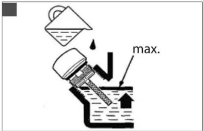
natural_image
Diagram of a mechanical component with a rotating arrow, no text or symbols present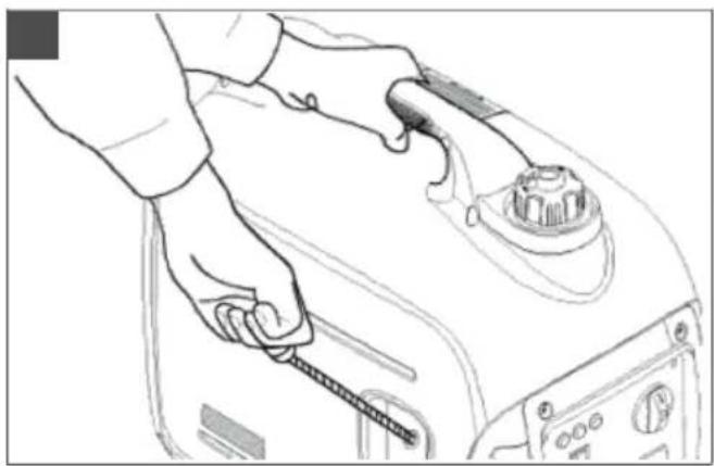
natural_image
Line drawing of a hand holding a tool on a mechanical device (no text or symbols)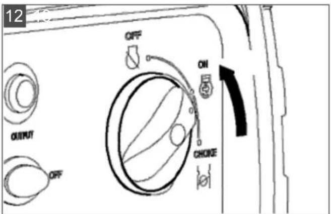
natural_image
Technical line drawing of a mechanical component with a curved arrow indicating rotation (no text or symbols)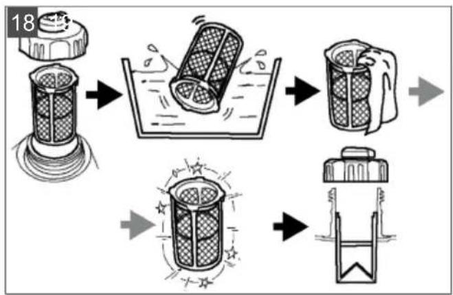
flowchart
graph TD
    A["Unrolled Filter"] --> B["Streamed Container"]
    B --> C["Flushed Container"]
    C --> D["Flushed Container"]
    D --> E["Flushed Container"]
    E --> F["Flushed Container"]
natural_image
Line drawing of a portable gas generator connected to a fuel can, with no visible text or symbols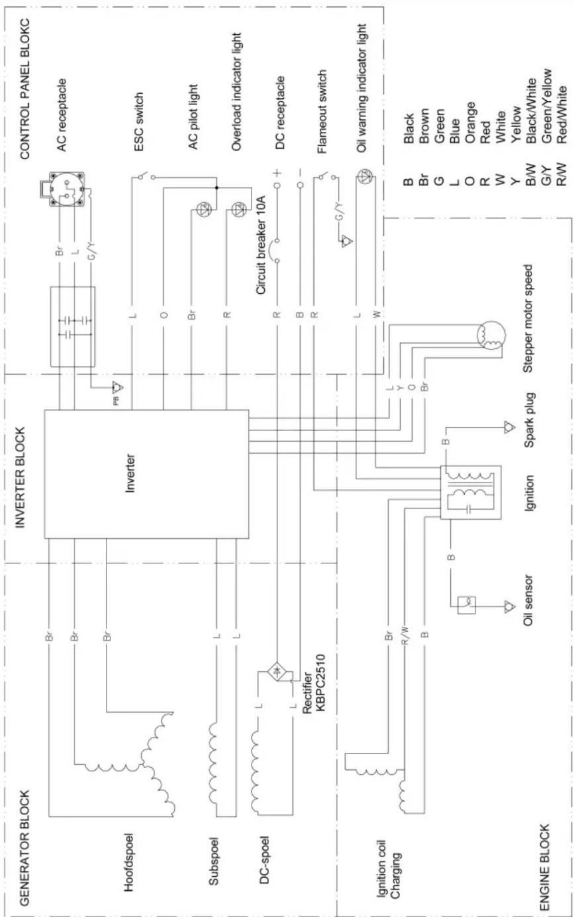
flowchart
graph TD
    subgraph GENERATOR_BLOCK
        A["Generator Block"] --> B["Inverter Block"]
        B --> C["Control Panel_BLOCK"]
    end

    subgraph ENGINE_BLOCK
        D["Engine Block"] --> E["Ignition coil Charging"]
        E --> F["Inverter Block"]
        F --> G["Control Panel_BLOCK"]

    A --> H["Br"]
    A --> I["Br"]
    A --> J["Br"]
    A --> K["PB"]
    B --> L["Br"]
    B --> M["L"]
    B --> N["G/Y"]
    B --> O["O"]
    B --> P["Br"]
    B --> Q["R"]
    B --> R["Circuit breaker 10A"]
    B --> S["D/C"]
    B --> T["DC receptacle"]
    B --> U["Flameout switch"]
    B --> V["Oil warning indicator light"]

    E --> W["Br"]
    E --> X["R/W"]
    E --> Y["B"]
    E --> Z["B"]
    E --> AA["L"]
    E --> AB["Y"]
    E --> AC["O"]
    E --> AD["R"]
    E --> AE["W"]
    E --> AF["Y"]
    E --> AG["B/W"]
    E --> AH["G/Y"]
    E --> AI["R/W"]

    subgraph INVERTER_BLOCK
        J --> AJ["Inverter Block"]
        AJ --> AK["CONTROL PANEL BLOCK"]
    end

    subgraph OUTPUT
        AL["Black"] --> AM["B"]
        AN["Brown"] --> AO["B"]
        AP["Green"] --> AQ["B"]
        AR["Blue"] --> AS["L"]
        AT["Orange"] --> AU["O"]
        AV["Red"] --> AW["R"]
        AX["White"] --> AY["W"]
        AZ["Y"] --> BA["Y"]
        BB["B/W"] --> BC["B/W"]
        BD["Black/White"] --> BE["B/W"]
        BF["Green/White"] --> BG["G/Y"]
        BH["Red/White"] --> BI["R/W"]

AL-KO 2000i

ca. 499 x 285 x 455 mm

ca. 21 kg
LC148F
e11*97/68SA*2010/26*2663*00
single cylinder engine / four-stroke / air-cooled / OHV
79~cm^3
1,6 kW
3000 min ^-1

E6TC/E6RTC
0,6 - 0,7 mm

Petrol
41
0,351

230 V / 50 Hz
1,6 kW (max. 1,8 kW)

L_pA = 64 dB(A), K = 2 dB(A)

L_wA=84 dB(A), K=2 dB(A)
1 About these operating instructions ..... 18
1.1 Symbols on the title page.... 18
1.2 Legends and signal words ...... 18
2 Product description 19
2.1 Designated use 19
2.2 Possible foreseeable misuse .... 19
2.3 Residual risks.... 19
2.4 Safety and protective devices ..... 19
2.5 Symbols on the device 19
2.6 Product overview (01) 20
3 Safety instructions .... 20
4 Start-up 21
4.1 Establishing the equipotential bond (02).... 21
4.2 Filling with operating fluids ...... 21
4.2.1 Safety when filling with petrol and oil 21
4.2.2 Operating material 22
4.2.3 Filling with petrol (03) 22
4.2.4 Filling with engine oil (04 - 07)..... 22
5 Operation 22
5.1 Starting the engine (08 - 12) ...... 22
5.2 Warning and indicator lights (13) ..... 23
5.2.1 Oil warning light – red (13/1) ..... 23
5.2.2 Overload indicator light – red (13/2) 23
5.2.3 Alternating current (AC) indicator light – green (13/3) 23
5.3 Direct current (DC) safety switch (14) 23
5.4 Connecting an appliance.... 23
5.5 Unplugging appliance.... 24
5.6 Connecting a 12 V car battery for charging 24
5.7 Switching off the engine (15 - 17) ..... 24
6 Maintenance and care 24
6.1 Maintenance intervals 24
6.2 Changing the oil 24
6.3 Cleaning the fuel tank screen (18) ..... 25
6.4 Changing the spark plug (19, 20)..... 25
7 Help in case of malfunctions ...... 25
8 Transport.... 26
9 Storage.... 26
10 Disposal.... 26
11 After-Sales / Service.... 26
12 Guarantee 27
1 ABOUT THESE OPERATING INSTRUCTIONS
The German version is the original operating instructions. All additional language versions are translations of the original operating instructions.
■ Always safeguard these operating instructions so that they can be consulted if you need any information about the appliance.
■ Only pass on the appliance to other persons together with these operating instructions.
■ Comply with the safety and warning information in these operating instructions.
1.1 Symbols on the title page
Symbol Meaning

It is essential to read through these operating instructions carefully before start-up. This is essential for safe working and trouble-free handling.

Operating instructions

Never operate the petrol powered device in the vicinity of open flames or heat sources.
1.2 Legends and signal words
⚠️ DANGER! Denotes an imminently dangerous situation which will result in fatal or serious injury if not avoided.
WARNING! Denotes a potentially dangerous situation which can result in fatal or serious injury if not avoided.
CAUTION! Denotes a potentially dangerous situation which can result in minor or moderate injury if not avoided.
IMPORTANT! Denotes a situation which can result in material damage if not avoided.
NOTE Special instructions for ease of understanding and handling.
2 PRODUCT DESCRIPTION
2.1 Designated use
This device is intended for the connection of individual electrical appliances in non-commercial applications. The connecting cables should be kept as short as possible. No appliances may be connected when starting the generator.
This appliance is intended solely for use in non-commercial applications. Any other use as well as unauthorised conversions or modifications are regarded as contrary to the intended use and will result in voiding of the warranty as well as loss of conformity; the manufacturer will thus decline any responsibility for damage and/or injury suffered by the user or third parties.
It is essential to consult a qualified electrician before connecting the generator to stationary equipment such as heaters, mobile homes or caravans.
The generator is operated with unleaded petrol.
2.2 Possible foreseeable misuse
The device is not intended for commercial, trade or industrial use. We assume no warranty if the device is used for commercial, trade or industrial purposes, on construction sites or in equivalent facilities.
The generator is not suitable for supplying power to buildings.
2.3 Residual risks
Even during correct use of the appliance, there is always a certain residual risk that cannot be excluded. Depending on the use, the following potential risks can be derived from the type and construction of the appliance:
Risk of electric shock if:
An equipotential bond is not properly established
■ External residual current devices (RCD) are not connected
There are insulation faults in connected electrical appliances
The maximum cable length is exceeded
■ Parts of the generator become very hot during operation and remain hot even after the generator is switched off.
■ Hot exhaust gases escape from the exhaust silencer.
2.4 Safety and protective devices
WARNING! Risk of injury. Defective and disabled safety and protective devices can result in serious injury.
■ Have any defective safety and protective devices repaired.
■ Never disable safety and protective devices.
2.5 Symbols on the device
Symbol Meaning

Pay special attention when handling this device!

Read the operating instructions before starting operation!
Danger of poisoning due to exhaust gases!

Do not operate the device in closed rooms or poorly ventilated working areas (e.g. garage).
There is a danger of electric shock and short-circuit.

Risk of fires! Pay special attention when handling fuel and oil!
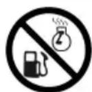
Allow the device to cool down completely before filling with fuel or oil!

Wear ear protection!
Symbol Meaning
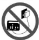
Do not connect the generator to the household mains network!

Unplug all appliances when working on the generator.

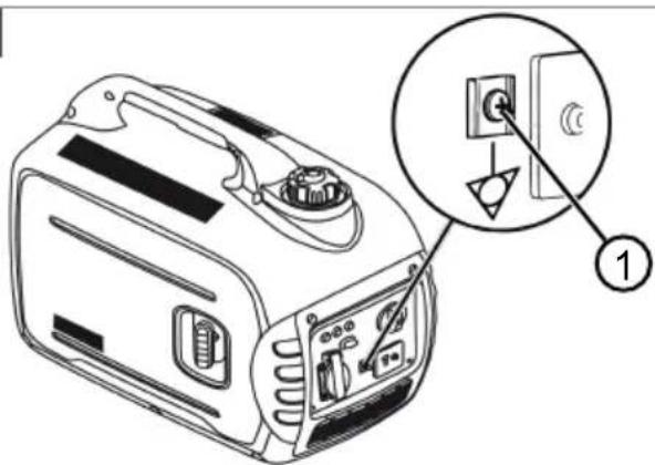
Terminal for equipotential bond
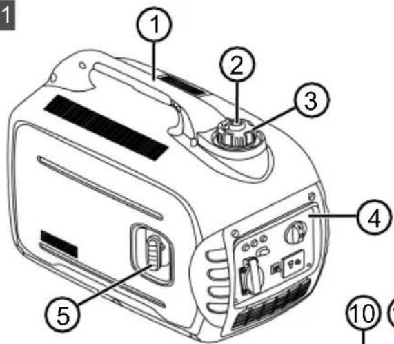
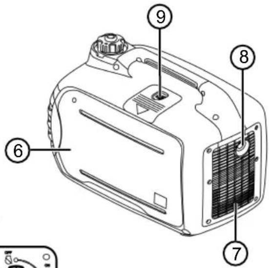
2.6 Product overview (01)
Device
No. Component
1 Handle
2 Fuel filler cap breather valve
3 Fuel filler cap
4 Operating panel
5 Pull-cord starter
6 Engine cover
7 Ventilation grille
8 Exhaust silencer
9 Spark plug maintenance cover
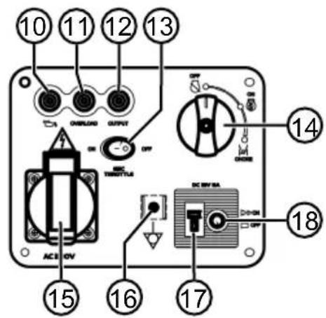
Operating panel
No. Component
10 Oil warning light
11 Overload indicator light
12 Alternating current (AC) indicator light
13 ESC (Engine Smart Control)
14 STOP/START/CHOKE rotary switch
15 230 V AC output
16 Terminal for equipotential bond
17 12 V DC output
18 Direct current (DC) safety switch
3 SAFETY INSTRUCTIONS
Risk of electric shock! Do not operate the device in the case of rain, moisture or high humidity.
■ Use the device only when it is in a flawless technical condition! Before every use, check that the device is undamaged and that there are no exposed electric cables.
■ Never store the machine with fuel in the tank inside a room in which petrol vapours could come into contact with naked flames, a heat source or sparks.
- Keep the area around the engine, exhaust, battery box and fuel tank free from dirt, petrol and oil.
- Do not store any combustible or highly flammable objects or materials in the area of the exhaust outlet.
- Do not operate the device in closed rooms or poorly ventilated working areas (e.g. garage). Do not operate the device underground. The exhaust gases contain poisonous carbon monoxide as well as other harmful substances.
- Do not connect the generator to the household mains network!
■ The generator must be securely earthed.
- Keep bystanders away!
■ The user is responsible for accidents involving other people and their property.
Children or other people who are not familiar with the operating instructions must not be allowed to use the device.
■ Make sure that children are not present in the vicinity of the device when it is operating or climb onto the device and do not play with the device.
■ Comply with local regulations on the minimum age of people operating the device.
- Do not operate the device while under the influence of alcohol, drugs or medication.
■ Wear appropriate protective clothing:
Long trousers
■ Sturdy, non-slip footwear
Ear protection
■ Make sure you are standing safely, particularly on slopes and uneven ground.
■ Use the device only during daylight hours or with good artificial lighting.
■ Comply with working time regulations in force in your country.
- Do not leave the operational device unsupervised.
■ Never operate the device or the appliances to be connected to it with damaged protective devices. Inspect the device for damage before every use. Have damaged parts replaced prior to use.
- Inspect the device for damage and have damaged parts repaired before restarting the device.
In the following cases, switch off the engine, wait for the device to come to a standstill and disconnect the spark plug connector:
■ Before leaving the device
■ After malfunctions have occurred
If malfunctions and unusual vibrations occur in the device
For transport
■ Connect the spark plug connector and start the engine:
■ After remedying of malfunctions (see malfunction table) and testing the device
■ After cleaning the device
- Do not eat or drink when adding petrol or engine oil.
■ Do not inhale petrol vapours.
■ Never lift or carry the device with the engine running. - Inspect all operating elements, safety devices, nuts, bolts and studs of the device for completeness, tightness and sound condition.
- Do not use bare wires for connection to electrical appliances. Always use compatible cables and plugs.
- Observe the maximum permitted cable length when using extension leads or a mobile power distribution cabinet:
■ with ∅ 1.5 mm²: max. 60 m
■ with ∅ 2.5 mm²: max. 100 m
4 START-UP
4.1 Establishing the equipotential bond (02)
When connecting a single electrical appliance, safe operation is ensured by the design and function of the generator. It can be put into operation by an electrical layman, as no protective equipotential bond has to be established and no testing is required before commissioning.
If several electrical appliances are to be connected, the generator must be connected to an equipotential bonding bar by means of an equipotential bonding conductor. The equipotential bonding conductor must be an insulated copper wire of at least 2.5 mm^2 with mechanically protected routing or at least 4 mm^2 with unprotected routing. This work must be carried out by a qualified electrician.
The generator has no internal residual current device (RCD).
If only one appliance is connected, no residual current device or isolating transformer is required.
■ Each additional connected appliance requires its own external residual current device (30 mA).
■ Each additional connected appliance with increased electrical hazard must be connected via an isolating transformer instead of a 30 mA residual current device.
■ All appliances connected via a socket strip must have their own residual current device (30 mA).
Connecting the equipotential bonding conductor
- Loosen nut (02/1).
- Push the stripped end of the wire under the nut.
- Tighten the nut to clamp the wire end.
- Connect the other end of the wire to the equipotential bonding bar.
4.2 Filling with operating fluids
4.2.1 Safety when filling with petrol and oil
⚠️ DANGER! Risk of poisoning. The engine exhaust gases contain carbon monoxide that can kill a person within a few minutes.
- Operate the engine only outdoors, never in a closed room.
■ Do not inhale the engine exhaust gases.
■ Switch off the engine if you feel nauseous, dizzy or weak during use. Immediately consult a doctor.
■ Store petrol and engine oil only in containers designed for this purpose. -
Fill and drain petrol and engine oil only outdoors and with the engine cooled down.
-
Do not add petrol or engine oil with the engine running.
- Do not overfill the tank as the petrol can expand.
■ Do not smoke when refuelling. - Do not open the fuel filler cap when the engine is running or hot.
- Replace the tank or fuel filler cap if damaged.
■ Always close the fuel filler cap tightly.
■ If petrol has leaked out:
Do not start the engine.
- Avoid start attempts.
■ Thoroughly clean the device.
- Allow the engine to cool down before refilling with petrol and avoid spilling.
- Spilt fuel can cause damage to plastic parts. Wipe up spilled fuel immediately. The warranty does not cover damage to plastic parts caused by fuel.
■ If engine oil has leaked out:
Do not start the engine.
- Pick up leaked engine oil using an oil binding agent or cloth and dispose of properly.
■ Thoroughly clean the device.
NOTE Dispose of used engine oil in an environmentally responsible manner! We recommend disposing of waste oil in a closed container at a recycling centre or customer service centre. Do not dispose of waste oil:
In domestic waste
In sewers or drains
In the ground
4.2.2 Operating material
Before starting operation, the device must be filled with engine oil and the tank filled with petrol.
| Petrol Engine oil | ||
| Grade Regular | pet-rol / unleaded | SAE 10W-30 |
| Filling capacity | 4 | 0.35 l | |
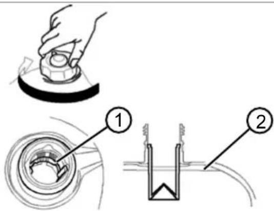
4.2.3 Filling with petrol (03)
⚠️ DANGER! Risk of explosion and fire. An escaping petrol/air mixture can cause an explosive atmosphere. Deflagation, explosion and fire can lead to serious and even fatal injuries if fuel is not handled properly.
■ Do not smoke when dealing with petrol.
■ Only handle petrol out of doors and never in enclosed spaces.
-
Unscrew the fuel filler cap and place to one side in a clean place.
-
Pour in petrol through a funnel:
■ Fill only up to the red line (03/1)
■ Max. filling level (03/2)
- Securely tighten the fuel filler cap and clean the tank filler neck.
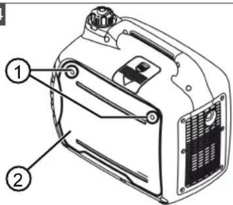
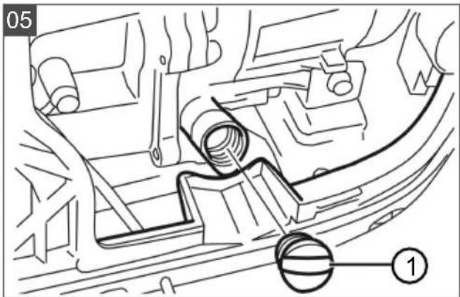
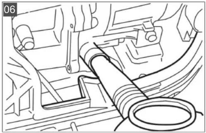
4.2.4 Filling with engine oil (04 - 07)
- Place the appliance on an even horizontal surface.
- Loosen screws (04/1).
- Remove engine cover (04/2).
- Unscrew the oil filler cap and place to one side in a clean place (05/1).
- Pour in oil via a funnel (06). Note: Do not exceed the maximum filling level (07).
- Securely tighten and clean the oil filler neck.
- Install the engine cover again and secure.
5 OPERATION
5.1 Starting the engine (08 - 12)
DANGER! Risk of poisoning. The engine exhaust gases contain carbon monoxide that can kill a person within a few minutes.
■ Only start and operate the engine in the open air.
■ Never operate the engine in enclosed areas even with the windows and doors open.
■ Do not inhale the engine exhaust gases.
■ Switch off the engine if you feel nauseous, dizzy or weak during use. Immediately consult a doctor.
CAUTION! Risk of injury! Danger of kickback: The starter cable can return faster to the engine than the cable can be released.
■ Anticipate a sudden jolt when the starter cable has been pulled.
The interval between starting attempts should be 10 seconds to avoid discharging the starter battery too quickly.
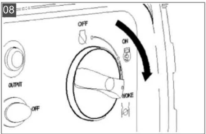
- Actuate the choke (08):
■ For a cold start, turn the rotary knob to CHOKE.
■ For a warm start, turn the rotary knob to ON.
Note: If the device still does not start after two attempts, turn the rotary knob to CHOKE.
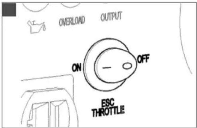
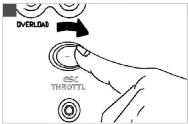
- Set the ESC switch to "OFF" (09).
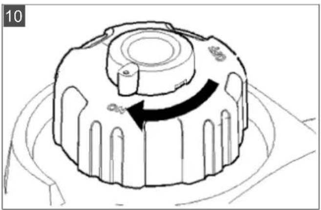
- Turn the fuel filler cap breather valve to "ON" (10).
- Actuating the pull-cord starter (11):
■ Pull out the starter cable slowly until it is taut.
■ Then pull out the starter cable briskly and allow it to wind back in slowly.
Note: If the device still does not start after two attempts, follow the instructions for the choke.
- Turn the rotary knob to "ON" approx. 30 seconds after the engine has started (12).
ESC function (Engine Smart Control) (09)
- When starting the engine with the ESC switch in position “ON” and no consumers connected to the generator:
At an ambient temperature below 0^ C, allow the engine to warm up at rated speed (5000 rpm) for 5 minutes.
At an ambient temperature below 5°C, allow the engine to warm up at rated speed (5000 rpm) for 3 minutes.
After this time, the ESC function regulates the engine speed to the required operating speed depending on the number of connected appliances and the associated load.
If the ESC switch is turned to "OFF", the engine runs at rated speed (5000 rpm) irrespective of whether or not any electrical appliances are connected.
The ESC switch must be turned to OFF if electrical appliances are connected that require a high starting current (e.g. compressor or immersion pump).
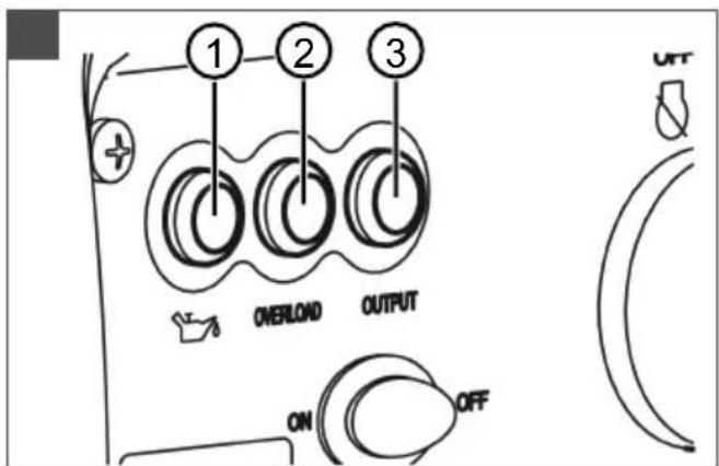
5.2 Warning and indicator lights (13)
5.2.1 Oil warning light – red (13/1)
If the oil level drops below “Minimum” the oil warning light comes on and the engine stops automatically. The oil must be topped up before the engine can be started again.
5.2.2 Overload indicator light – red (13/2)
The overload indicator light comes on if the generator is overloaded by a connected electrical appliance, the inverter control unit overheats, or the AC output voltage increases. Power generation is stopped to protect the generator and all connected electrical appliances. The green alternating current (AC) indicator light (13/3) is no longer lit. The engine continues to run.
- Switch off all connected electrical appliances.
- Switching off the engine
- Reduce the total power of the connected electric appliances to below the maximum rated output power of the generator (i.e. disconnect appliances).
- Check the ventilation grille and operating panel for soiling and clean, if necessary.
- After checking, start the engine again.
NOTE When using electrical appliances that require a high starting current (e.g. compressor or immersion pump), the overload indicator light may come on briefly. That is not a malfunction.
5.2.3 Alternating current (AC) indicator light – green (13/3)
The AC indicator light comes on if the engine is running and power is being generated.
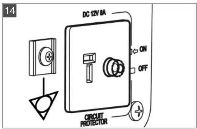
5.3 Direct current (DC) safety switch (14)
The DC safety switch automatically switches to OFF when the electric power of the connected appliances exceeds the operating current. To use the generator again, press the DC safety switch to switch it to ON.
If the DC safety switch switches to OFF, reduce the total power of the connected appliances to below the maximum rated output of the generator (i.e. disconnect appliances).
- Please contact the manufacturer's service centre if the DC safety switch constantly switches to "OFF".
5.4 Connecting an appliance
The total power of all connected electric appliances must not exceed the maximum rated power of the generator.
- Check whether the AC indicator light is lit.
- Connect the appliance to the socket of the generator.
If several appliances are to be connected, first plug in and switch on one appliance, then plug in and switch on the next appliance.
5.5 Unplugging appliance
- Unplug the appliance from the socket of the generator.
5.6 Connecting a 12 V car battery for charging

WARNING! Risk of fire and explosion
when charging. An incorrectly connected car battery can explode and cause serious injuries.
- Do not reverse the charging cables when connecting to the car battery.
-
Observe the manufacturer's instructions on charging the car battery.
-
Start the engine.
- Connect the battery charging cable to the 12 V DC output.
- Connect the red charging cable to the positive (+) terminal of the car battery.
- Connect the black charging cable to the negative (-) terminal of the car battery.
- Turn the ESC switch to "OFF" to start charging.
5.7 Switching off the engine (15 - 17)
Switch off the engine only when the generator has been running for 30 seconds under no load (i.e. with no appliances connected).
- Set the ESC switch to "OFF" (15).
- Unplug the appliance from the socket of the generator.
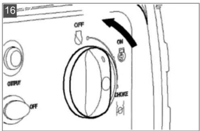
- Turn the rotary knob to "OFF" (16).
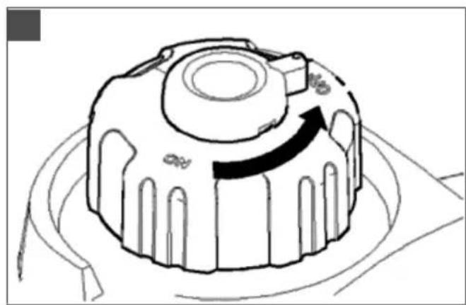
- Turn the fuel filler cap breather valve to "OFF" (17).

CAUTION! Risk of burns. Parts of the gen-
erator become very hot during operation and remain hot even after the generator is switched off.
- Allow the device to cool down before transporting it or using it again.
6 MAINTENANCE AND CARE

CAUTION! Risk of injury. A running engine
can result in injuries and electric shock.
■ Switch off the engine and disconnect the spark plug connector before carrying out any maintenance or service work.
The engine may run on. Switch off the engine and check that the engine has come to a standstill!
■ Clean the device after every use.
- Do not spray the device with water. Penetrating water can lead to malfunctions (ignition system, carburettor, electrical components).
■ Always replace a defective silencer.
6.1 Maintenance intervals
Before every use
■ Check the engine oil level
- Inspect the air filter
- Carry out a visual inspection for damage
After 20 operating hours or 1 month after first use
Change the oil
Every 100 operating hours or every 6 months
■ Clean the air filter ^2)
Change the oil
■ Clean the spark plug
Every 300 operating hours or once a year
- Replace the spark plug
■ Set the valve backlash 1)
In addition every 300 operating hours
■ Clean the cylinder head 1)
■ Flush the fuel tank and fuel filter ^1)
- Replace the petrol hose ^1)
1) This maintenance work may be carried out only by service centres and authorised specialist companies.
2) If the generator is used in a wet or very dirty environment, the maintenance work must be carried out earlier or at shorter intervals.
6.2 Changing the oil

CAUTION! Risk of burns. Parts of the gen-
erator become very hot during operation and remain hot even after the generator is switched off.
- Allow the device to cool down before transporting it or using it again.
- Place the appliance on an even horizontal surface.
- Start the engine and allow it to run for approx. 5 minutes.
- Turn the rotary knob to "OFF" (16).
- Turn the fuel filler cap breather valve to "OFF" (17).
- Loosen screws (04/1).
- Remove engine cover (04/2).
- Unscrew the oil filler cap and place to one side in a clean place (05/1).
- Place an oil collecting vessel under the engine.
- Tilt the device to fully drain the oil.
- Place the device on an even horizontal surface again.
- Pour in new engine oil up to the maximum filling level (06, 07).
Note: Observe the filling capacity and oil grade (see chapter 4.2.2 "Operating material", page 22).
Caution: Risk of engine damage: Do not tilt the device during filling and do not fill beyond the maximum filling level. -
Tightly close the oil filler opening with the oil filler cap and clean the oil filler neck.
-
Install the engine cover again and secure. If engine oil has leaked out:
■ Do not start the engine.
- Pick up leaked engine oil using an oil binding agent or cloth and dispose of properly.
■ Thoroughly clean the device.
NOTE Dispose of used engine oil in an environmentally responsible manner! We recommend disposing of waste oil in a closed container at a recycling centre or customer service centre. Do not dispose of waste oil:
In domestic waste
In sewers or drains
In the ground
6.3 Cleaning the fuel tank screen (18)
WARNING! Danger of explosion and fire.
Escaping fuel will create an explosive petrol/air mixture. Deflagration, explosion and fire can lead to serious and even fatal injuries if fuel is not handled properly.
-
Fill the fuel tank only outdoors and not with the engine running or hot.
■ Do not smoke when handling fuel. -
Unscrew the fuel filler cap and place to one side in a clean place.
- Remove the fuel tank screen.
- Clean the fuel tank screen with petrol.
- Rub the fuel tank screen dry.
- Install the fuel tank screen.
- Clean and tightly close the fuel filler cap. If petrol has leaked out:
■ Do not start the engine.
- Avoid start attempts.
■ Thoroughly clean the device.
- Allow the engine to cool down before refilling with petrol and avoid spilling.
■ Spilt fuel can cause damage to plastic parts. Wipe up spilled fuel immediately. The warranty does not cover damage to plastic parts caused by fuel.
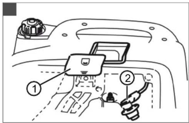
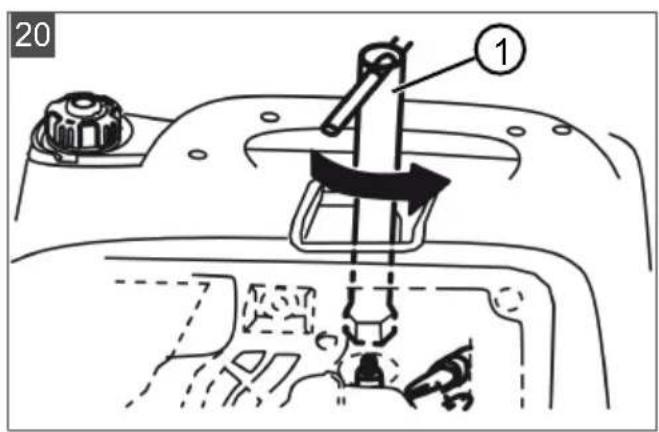
6.4 Changing the spark plug (19, 20)
- Remove the cover from the housing (19/1).
- Remove spark plug connector (19/2).
- Insert spark plug wrench (20/1) through the opening and on to the spark plug.
-
Unscrew the old spark plug.
-
Screw in the new spark plug by hand and tighten using the spark plug wrench (torque 20 Nm).
Note: Use the spark plug type indicated in the technical data.
- Install the cover again.
7 HELP IN CASE OF MALFUNCTIONS
CAUTION! Risk of injury. Sharp-edged and moving appliance parts can lead to injury.
■ Always wear protective gloves during maintenance, care and cleaning work!
NOTE For malfunctions that are not listed in this table or that you cannot resolve yourself, please contact our customer service.
| Malfunction Remedy | |
| Engine does not start. | Fill with petrol. |
| For a cold start, turn the ro- tary knob to CHOKE. | |
| Turn the fuel filler cap breather valve to "ON". | |
| Oil warning light comes on: Top up with oil. | |
| Check spark plugs and re- place, if necessary. | |
| Clean air filter. | |
| Unplug appliances. | |
| Engine loses power. | Clean air filter. |
| Unplug some appliances because the maximum rat- ed power of the generator has been exceeded. | |
| No power is gen- erated. | Alternating current (AC) in- dicator light does not comes on: Start the engine again. |
| Direct current (DC) safety switch is in position “OFF”: Turn safety switch to posi- tion “ON”. | |
8 TRANSPORT
WARNING! Danger of explosion and fire.
Fire and explosion caused by leaking fuel and oil and petrol fumes can cause serious injuries.
■ Always transport the power generator safely and upright in the normal operating position and with the tank as empty as possible.
-
Lift and/or carry the generator at the handle.
-
Secure the generator with straps or ropes for transport so that it cannot slip.
9 STORAGE
WARNING! Danger of explosion and fire.
Petrol and oil are highly flammable. Fire can lead to serious injuries.
- Do not store the appliance close to naked flames or sources of heat.
- Do not store the appliance in a room in which electric tools are operated.
- Allow the engine to cool down.
■ Store the device in a dry place out of the reach of children and unauthorised persons.
■ Store the device where it is protected from frost.
■ Empty the petrol tank.
■ Remove the spark plug connector.
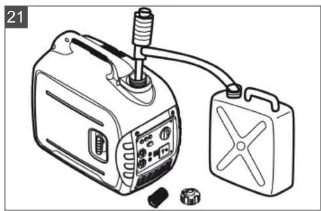
Drain the petrol (21)
Refuelled devices can release petrol vapours into the air during storage. On evaporation, petrol residues in the carburettor can cause components to stick and thus lead to malfunctions.
- Pump off the petrol into a suitable fuel container.
Covering the generator
- Store the generator in a clean, dry place protected against moisture and humidity.
- Cover the generator using suitable means to prevent dirt and dust deposits in the device.
10 DISPOSAL
Petrol and motor oil do not belong in household waste or the public sewer system, but should be collected and disposed of separately.
Before disposing of the device you must empty the fuel tank and the engine oil tank!
Packaging, equipment and accessories are made from recyclable materials, and must be disposed of accordingly.
11 AFTER-SALES / SERVICE
In the event of questions of warranty, repair or spare parts, please contact your nearest AL-KO Service Centre. These can be found on the Internet at:
www.al-ko.com/service-contacts
12 GUARANTEE
We will remedy any material or manufacturing defects discovered in the device during the statutory period of limitation for claims for defects by repair or replacement at our discretion. The period of limitation is determined in each case by the law of the country in which the device was purchased.
Our warranty promise applies only if:
■ These operating instructions are observed
The device is handled correctly
■ Original spare parts have been used
The warranty becomes void in the case of:
■ Unauthorised repair attempts
■ Unauthorised technical modifications
■ Use for other than the intended purpose
The warranty does not include:
■ Paint damage attributable to normal wear
■ Wear parts that are marked with a box xxxxxx (x) on the spare parts card
The warranty period commences with the purchase by the first end user. The date on the proof of purchase is decisive. In the event of a warranty claim, please contact your dealer or the nearest authorised customer service centre with this declaration and the original proof of purchase. This declaration does not affect the purchaser's statutory claims for defects against the vendor.
VERTALING VAN DE ORIGINELE GEBRUIKERSHANDLEIDING
Inhoudsopgave
2 PRODUCTOMSCHRIJVING
2.1 Beoogd gebruik
www.al-ko.com/service-contacts
12 GARANTIE
www.al-ko.com/service-contacts
12 GARANZIA
www.al-ko.com/service-contacts
12 ZÁRUKA
www.al-ko.com/service-contacts
12 GARANTI
www.al-ko.com/service-contacts
12 GARANTI
6 VEDLIKEHOLD OG PLEIE
www.al-ko.com/service-contacts
12 GARANTI
www.al-ko.com/service-contacts
12 ZÁRUKA
11 SERVISNA SLUŽBA/SERVIS
www.al-ko.com/service-contacts
12 JAMSTVO
Eventualne greške u materijalu ili proizvodnji na uređaju uklonit ćemo tijekom zakonskoga roka zastare za jamstvo na nedostatke prema vlastitom izboru popravljanjem ili zamjenskom dostavom. Rok zastare određuje se prema pravu države u kojoj je uređaj kupljen.
www.al-ko.com/service-contacts
12 GARANTII
www.al-ko.com/service-contacts
12 GARANTIJA
www.al-ko.com/service-contacts
12 ГАРАНТИЯ
Imported by: AL-KO Gardentech UK Ltd, Murray way, Wincanton, Somerset, BA9 9RS / UK | +44 (0) 1963 828055 shop.uk@al-ko.com | www.alko-garden.uk
AL-KO Service: www.al-ko.com/service-contacts