DP19Vario - Drill SCHEPPACH - Free user manual and instructions
Find the device manual for free DP19Vario SCHEPPACH in PDF.
| Product type | Bench drill press |
| Brand | Scheppach |
| Model | DP19Vario |
| Input voltage | 230-240 V~, 50 Hz |
| Rated power | 550 W |
| Motor speed | 1490 min⁻¹ |
| Output speed (continuously adjustable) | 440 - 2 580 min⁻¹ |
| Chuck mount | B16 |
| Chuck capacity | 1.5 - 13 mm |
| Drilling depth | 60 mm |
| Drill table | 190 x 190 mm |
| Table angle adjustment | 45° - 0° - 45° |
| Column diameter | 59.5 mm |
| Height | 870 mm |
| Weight | 27 kg |
| Laser class | 2 |
| Laser wavelength | 650 nm |
| Laser power | < 1 mW |
| Sound pressure level (LpA) | 73.8 dB (uncertainty 3 dB) |
| Sound power level (LWA) | 86.8 dB (uncertainty 3 dB) |
| Vibration emission value (a_h) | 1.7 m/s² (uncertainty 1.5 m/s²) |
| Machinable materials | Metal, wood, plastic, tile |
| Main functions | Drilling, reaming, centering drilling, countersinking |
| Safety equipment | Foldable chip guard, emergency stop (red switch), no-volt release |
| Maintenance and cleaning | Clean with brush or vacuum, lubricate moving parts, do not use solvents |
| Wear parts | V-belt, drill bit, battery |
| Repairability | Have repairs carried out by a qualified specialist, use only original spare parts |
Frequently Asked Questions - DP19Vario SCHEPPACH
User questions about DP19Vario SCHEPPACH
0 question about this device. Answer the ones you know or ask your own.
Ask a new question about this device
Download the instructions for your Drill in PDF format for free! Find your manual DP19Vario - SCHEPPACH and take your electronic device back in hand. On this page are published all the documents necessary for the use of your device. DP19Vario by SCHEPPACH.
USER MANUAL DP19Vario SCHEPPACH
natural_image
Black-and-white photo of a vintage manual drill press with no visible text or symbols on the device body.
| DE | TischbohrmaschineOriginalbetriebsanleitung | 7 |
| GB | Bench drillTranslation of original instruction manual | 24 |
| FR | Perceuse à colonne d'établiTraduction des instructions d'origine | 38 |
| IT | Trapano da tavoloLa traduzione dal manuale di istruzioni originale | 53 |
| NL | TafelboormachineVertaling van de originele gebruikshandleiding | 68 |
| ES | Taladradora de mesaTraducción del manual de instrucciones original | 82 |
| PT | Berbequim de bancadaTradução do manual de operação original | 97 |
| CZ | Stolní vrtačkaPřeklad originálního návodu k obsluze | 112 |
| SK | Stolová vítačkaPreklad originálneho návodu na obsluhu | 126 |
| HU | Asztali fúrógépEredeti használati utasítás fordítása | 140 |
| PL | Wiertarka stołowaTłumaczenie oryginalnej instrukcji obsługi | 154 |
| HR | Stolna bušilicaPrijevod originalnog priručnika za uporabu | 169 |
| SI | Namizni vrtalni strojPrevod originalnih navodil za uporabo | 182 |
| EE | LauapuurmasinOriginaalkäitusjuhendi tõlge | 196 |
| LT | Stalinės gręžimo staklėsOriginalios naudojimo instrukcijos vertimas | 209 |
| LV | Galda urbjmašīnaOriginālās lietošanas instrukcijas tulkojums | 222 |
| SE | BänkborrmaskinÖversättning av original-bruksanvisning | 236 |
| FI | PöytäporakoneKäännös alkuperäisestä käyttöohjeesta | 249 |
| DK | BænkboremaskineOversættelse fra den oprindeligebetjeningsvejledning | 262 |
natural_image
Mechanical assembly diagram showing a drill bit with labeled parts (no readable text or symbols)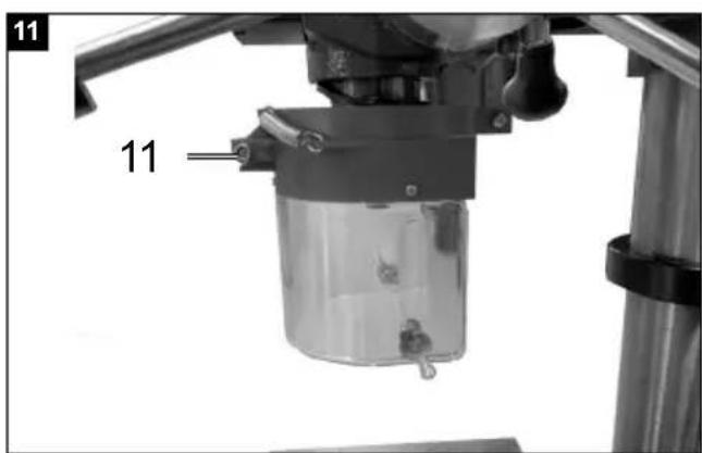

Günzburger Straße 69
D-89335 Ichenhausen
Verehrter Kunde
Homepage: https://www.scheppach.com/de/service
Explanation of the symbols on the product
Symbols are used in this manual to draw your attention to potential hazards. The safety symbols and the accompanying explanations must be fully understood. The warnings themselves will not rectify a hazard and cannot replace proper accident prevention measures.
 | Warning! Disregard results in a risk of death or injury, or damage to the tool! |
 | Read the operating and safety instructions before start-up and follow them! |
 | Wear eye protection! |
 | Wear hearing protection! |
 | If dust builds up, wear respiratory protection! |
 | Do not leave long hair loose. Use a hair net. |
 | Do not wear gloves. |
 | Attention! Laser radiation |
 | The product complies with the applicable European directives. |
Table of contents: Page:
- Introduction....26
- Device description (Fig. 1 - 2)....26
- Scope of delivery 26
- Proper use 27
- General safety information 27
- Technical data....30
- Before commissioning 30
- Assembly 31
- Operation....32
- Electrical connection 34
- Cleaning and maintenance.... 34
- Storage 35
- Disposal and recycling.... 35
- Troubleshooting 36
- Declaration of conformity 278
1. Introduction
Manufacturer:
Scheppach GmbH
Günzburger Straße 69
D-89335 Ichenhausen
Dear Customer
We hope your new tool brings you much enjoyment and success.
Note:
In accordance with the applicable product liability laws, the manufacturer of this device assumes no liability for damage to the device or caused by the device arising from:
- Improper handling,
• Non-compliance with the operating manual,
• Repairs carried out by third parties, unauthorised specialists.
• Installing and replacing non-original spare parts
• Application other than specified - Failure of the electrical system in the event of the electrical regulations and VDE provisions 0100, DIN 57113 / VDE0113 not being observed
Please consider:
Read through the complete text in the operating manual before installing and commissioning the device.
The operating manual is intended to help the user to become familiar with the machine and take advantage of its application possibilities in accordance with the recommendations.
The operating manual includes important instructions for safe, proper and economic operation of the device, for avoiding danger, for minimising repair costs and downtimes, and for increasing the reliability and extending the service life of the device.
In addition to the safety instructions in this operating manual, you must also observe the regulations applicable to the operation of the device in your country.
Keep the operating manual package with the machine at all times and store it in a plastic cover to protect it from dirt and moisture. They must be read and carefully observed by all operating personnel before starting the work.
The device may only be used by personnel who have been trained to use it and who have been instructed with respect to the associated hazards.
The required minimum age must be observed.
In addition to the safety instructions in this operating manual and the separate regulations of your country, the generally recognised technical rules relating to the operation of such machines must also be observed.
We accept no liability for accidents or damage that occur due to a failure to observe this manual and the safety instructions.
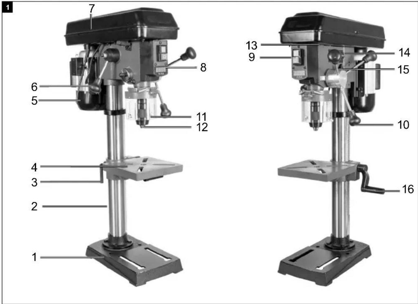
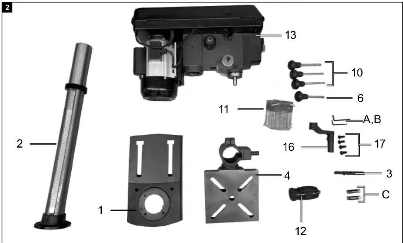
2. Device description (Fig. 1 - 2)
- Machine foot
- Column
- Clamping handle
- Drilling table
- Motor
- Speed adjustment lever (handle)
- V-belt cover
- Digital display
- On and off switch
- Handle
- Folding swarf protector
- Drill chuck (illustration may differ)
- Machine head
- Laser ON/OFF switch
- Depth indicator with stop
- Crank handle
- Hexagon screw
A. Allen key 4 mm
B. Allen key 3 mm
C. Battery
3. Scope of delivery
- Machine foot 1x
- Column 1x
- Clamping handle 1x
- Drilling table 1x
• Speed adjustment lever 1x - Handle 3x
- Folding swarf protector 1x
- Chuck 1x
- Machine head 1x
- Crank handle 1x
• M6 hexagonal bolt 4x - Battery 2x
- Allen key 2x
4. Proper use
The bench drill is designed for drilling in metal, wood, plastic and tiles. Straight shank drills from 1.5 mm to 13 mm drill diameter can be used.
The device is intended to be used by do-it-yourselfers. It was not designed for heavy commercial use. The tool is not to be used by persons under the age of 16. Children over the age of 16 may use the tool except under supervision. The manufacturer is not liable for damage caused by an improper use or incorrect operation of this device.
Please observe that our equipment was not designed with the intention of use for commercial or industrial purposes. We assume no guarantee if the equipment is used in commercial or industrial applications, or for equivalent work.
5. General safety information
General power tool safety warnings
⚠ WARNING! Read all safety warnings, instructions, illustrations and specifications provided with this power tool. Failure to follow all instructions listed below may result in electric shock, fire and/or serious injury.
Save all warnings and instructions for future reference.
The term "power tool" in the warnings refers to your mains-operated (corded) power tool or battery-operated (cordless) power tool.
Work area safety
a) Keep work area clean and well lit. Cluttered or dark areas invite accidents.
b) Do not operate power tools in explosive atmospheres, such as in the presence of flammable liquids, gases or dust. Power tools create sparks which may ignite the dust or fumes.
c) Keep children and bystanders away while operating a power tool. Distractions can cause you to lose control.
Electrical safety
a) Power tool plugs must match the outlet. Never modify the plug in any way. Do not use any adapter plugs with earthed (grounded) power tools. Unmodified plugs and matching outlets will reduce risk of electric shock.
b) Avoid body contact with earthed or grounded surfaces, such as pipes, radiators, ranges and refrigerators. There is an increased risk of electric shock if your body is earthed.
c) Do not expose power tools to rain or wet conditions. Water entering a power tool will increase the risk of electric shock.
d) Do not use the cable for another purpose, for example, carrying or hanging the power tool or pulling the plug out of the socket. Keep the cable away from heat, oil, sharp edges or moving device parts. Damaged or coiled cables increase the risk of an electric shock.
e) If you work with a power tool outdoors, only use extension cables that are also suitable for outdoor use. Using an extension cable suitable for outdoor use reduces the risk of an electric shock.
f) If you cannot avoid using the electrical tool in a wet environment, use a fault-current circuit breaker. Use of an RCD reduces the risk of electric shock.
Personal safety
a) Stay alert, watch what you are doing and use common sense when operating a power tool. Do not use a power tool while you are tired or under the influence of drugs, alcohol or medication. A moment of carelessness when using electrical tools can result in serious injuries.
b) Use personal protective equipment. Always wear eye protection. Protective equipment such as a dust mask, non-skid safety shoes, hard hat or hearing protection used for appropriate conditions will reduce personal injuries.
c) Prevent unintentional starting. Ensure the switch is in the off-position before connecting to power source and/or battery pack, picking up or carrying the tool. Carrying power tools with your finger on the switch or energising power tools that have the switch on invites accidents.
d) Remove any adjusting key or wrench before turning the power tool on. A tool or spanner that is located in a rotating device part may result in injuries.
e) Do not overreach. Keep proper footing and balance at all times. This enables better control of the power tool in unexpected situations.
f) Dress properly. Do not wear loose clothing or jewellery. Keep hair, clothing and gloves away from moving parts. Loose clothes, jewellery or long hair can be caught in moving parts.
g) If dust extraction and collection devices can be mounted, make sure that they are connected and used properly. Use of dust collection can reduce dust-related hazards.
h) Do not let familiarity gained from frequent use of tools allow you to become complacent and ignore tool safety principles. A careless action can cause severe injury within a fraction of a second.
Power tool use and care
a) Do not overload the device. Use the correct power tool for your application. The correct power tool will do the job better and safer at the rate for which it was designed.
b) Do not use the power tool if the switch does not turn it on and off. Any power tool that cannot be controlled with the switch is dangerous and must be repaired.
c) Disconnect the plug from the power source and/or remove the battery pack, if detachable, from the power tool before making any adjustments, changing accessories, or storing power tools. Such preventive safety measures reduce the risk of starting the power tool accidentally.
d) Store idle power tools out of the reach of children and do not allow persons unfamiliar with the power tool or these instructions to operate the power tool. Power tools are dangerous in the hands of untrained users.
e) Maintain power tools and accessories. Check whether moving parts function properly and do not get stuck and whether parts are broken or are damaged and thus adversely affect the electric tool function. If damaged, have the power tool repaired before use. Many accidents are caused by poorly maintained power tools.
f) Keep cutting tools sharp and clean. Properly maintained cutting tools with sharp cutting edges are less likely to bind and are easier to control.
g) Use the power tool, accessories and tool bits etc. in accordance with these instructions, taking into account the working conditions and the work to be performed. Use of the power tool for operations different from those intended could result in a hazardous situation.
h) Keep handles and grasping surfaces dry, clean and free from oil and grease. Slippery handles and grasping surfaces do not allow for safe handling and control of the tool in unexpected situations.
Service
a) Have your power tool serviced by a qualified repair person using only identical replacement parts. This will ensure that the safety of the power tool is maintained.
Safety instructions for drills
a) The drill must be secured. An incorrectly secured drill can move or topple and this can result in injuries.
b) The workpiece must be clamped or fastened to the workpiece support. Do not drill into workpieces that are too small to be securely clamped. Holding the workpiece by hand can lead to injuries.
c) Do not wear gloves. Gloves can be caught by rotating parts or drilling debris and thus cause injuries.
d) Keep your hands away from the drilling area whilst the electrical tool is running. Contact with rotating parts or drilling debris can cause injuries.
e) The drill must be turning before it makes contact with the workpiece. Otherwise, the drill bit can catch in the workpiece and this can result in an unexpected movement of the workpiece and cause injuries.
f) If the drill becomes jammed, stop pressing downwards and switch the electrical tool off. Investigate and rectify the cause of the jamming. Jamming can result in an unexpected movement of the workpiece and can result in serious injuries.
g) Avoid long pieces of drill swarf by interrupting the downward pressure at regular intervals. Sharp metal swarf can become tangled and lead to injuries.
h) Never remove drilling debris from the drilling area whilst the electrical tool is running. To remove swarf, move the drill away from the workpiece, switch off the electrical tool and wait until the drill has come to a standstill. Use an aid such as a brush or a hook to remove the swarf. Contact with rotating parts or drilling debris can cause injuries.
i) The permissible rotational speed for drill bits with a rated speed must be at least as high as the highest speed cited on the electrical tool. Accessories that rotate faster than permitted can break and fly off at high speed.
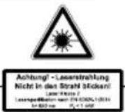
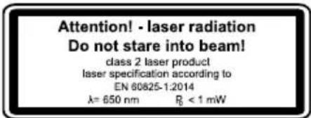
Attention: Laser radiation Do not stare into beam Laser class 2
Protect yourself and you environment from accidents using suitable precautionary measures!
- Do not look directly into the laser beam with unprotected eyes.
- Never look into the path of the beam.
- Never point the laser beam towards reflecting surfaces and persons or animals. Even a laser beam with a low output can cause damage to the eyes.
- Caution - methods other than those specified here can result in dangerous radiation exposure.
- Never open the laser module. Unexpected exposure to the beam can occur.
- If the device is not used for an extended period of time, the batteries should be removed.
- The laser may not be replaced with a different type of laser.
• Repairs of the laser may only be carried out by the laser manufacturer or an authorised representative.
Safety instructions for handling batteries
-
Always make sure that the batteries are inserted with the correct polarity (+ and -), as indicated on the battery.
-
Do not short-circuit batteries.
- Do not charge non-rechargeable batteries.
- Do not overcharge batteries!
-
Do not mix old and new batteries or batteries of different types or manufacturers! Replace an entire set of batteries at the same time.
-
Immediately remove used batteries from the device and dispose of them properly! Do not throw batteries away with household waste. Defective or used batteries must be recycled according to Directive 2006/66/EC. Return batteries and / or the device to the collection facilities offered. Contact your local authority or city administration for information about disposal options.
-
Do not allow batteries to heat up!
- Do not weld or solder directly on batteries!
-
Do not dismantle batteries!
-
Do not allow batteries to deform!
-
Do not throw batteries into fire!
-
Keep batteries out of the reach of children.
-
Do not allow children to replace batteries without supervision!
-
Do not keep batteries near fire, ovens or other sources of heat. Do not use batteries in direct sunlight or store them in vehicles in hot weather.
-
Keep unused batteries in the original packaging and keep them away from metal objects. Do not mix unpacked batteries or toss them together! This can lead to a short-circuit of the battery and thus damage, burns or even the risk of fire.
-
Remove batteries from the equipment when it will not be used for an extended period of time, unless it is for emergencies!
-
NEVER handle batteries that have leaked without appropriate protection. If the leaked fluid comes into contact with your skin, the skin in this area should be rinsed off under running water immediately. Always prevent the fluid from coming into contact with the eyes and mouth. In the event of contact, please seek immediate medical attention.
-
Clean the battery contacts and corresponding contacts in the device prior to inserting the batteries.
⚠ WARNING! This power tool generates an electromagnetic field during operation. This field can impair active or passive medical implants under certain conditions. In order to prevent the risk of serious or deadly injuries, we recommend that persons with medical implants consult with their physician and the manufacturer of the medical implant prior to operating the power tool.
Residual risks
The electric tool has been built according to state-of-the-art and the recognised technical safety rules. However, individual residual risks can arise during operation.
- Health hazard due to electrical power, with the use of improper electrical connection cables.
• Furthermore, despite all precautions having been met, some non-obvious residual risks may still remain. - Residual risks can be minimised if the "Safety instructions" and "Proper use" are observed along with the whole of the operating instructions.
- Do not load the machine unnecessarily: too much pressure when drilling quickly damages the tool attachment. This can lead to a reduction in the performance of the machine during machining and a reduction in accuracy.
- Avoid accidental starting of the machine: the operating button may not be pressed when inserting the plug in an outlet.
- Use the tool that is recommended in this manual. This is how to ensure that your device provides optimum performance.
- Keep your hands away from the work area, when the machine is in operation.
- Before maintaining or adjusting, switch off the machine and unplug the power plug.
6. Technical data
Rated input voltage 230-240V\~50 Hz
| Nominal power 550 W | |
| Motor speed 1490 min | -1 |
| Output speed (continuously adjustable) | 440 - 2580 min^-1 |
| Chuck adapter B16 | |
| Chuck | 1.5 - 13 mm. |
| Drilling table size | 190 x 190 mm |
| Angle adjustment | 45° - 0° - 45° |
| Drilling depth | 60 mm |
| Column diameter | 59.5 mm |
| Height | 870 mm |
| Weight | 27 kg |
| Laser class | 2 |
Laser wavelength 650mm
Power of laser 1mW
Technical changes reserved!
Noise and vibration
The noise values have been determined in accordance with EN 62841.
| Sound pressure level L_pA | 73.8 dB |
| Uncertainty K_pA | 3 dB |
| Sound power level L_WA | 86.8 dB |
| Uncertainty K_WA | 3 dB |
Wear hearing protection.
Excessive noise can result in a loss of hearing. Total vibration values (vector sum of three directions) determined according to EN 62841.
Vibration emission value a_h 1.7 ~m / s^2 Uncertainty K = 1.5 ~m / s^2
The specified vibration emission value has been measured according to a standardised testing procedure and can be used for comparison of one power tool with another; and may change depending on the way in which the power tool is used and in exceptional cases may be higher than the specified value.
The specified vibration emission value can be used to compare one power tool with another.
The specified vibration emission value can also be used for an initial estimation of the impair.
7. Before commissioning
- Open the packaging and carefully remove the device.
- Remove the packaging material, as well as the packaging and transport safety devices (if present).
- Check whether the scope of delivery is complete.
- Check the device and accessory parts for transport damage. In the event of complaints the carrier must be informed immediately. Later claims will not be recognised.
-
If possible, keep the packaging until the expiry of the warranty period.
-
Familiarise yourself with the product by means of the operating instructions before using for the first time.
- With accessories as well as wearing parts and replacement parts use only original parts. Replacement parts can be obtained from your dealer.
- When ordering please provide our article number as well as type and year of manufacture for your equipment.
⚠ WARNING!
The device and the packaging material are not children's toys! Do not let children play with plastic bags, films or small parts! There is a danger of choking or suffocating!
8. Assembly
⚠ Attention!
Always make sure the product is fully assembled before commissioning!
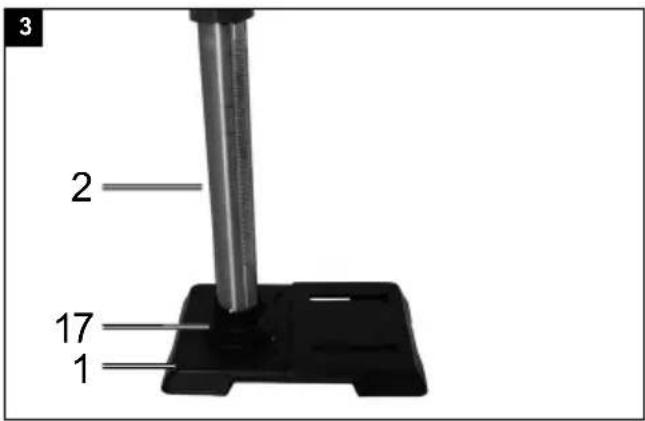
Column and machine foot, fig. 3
- Set the machine foot (1) down on the ground or the workbench.
- Place the column (2) on the base plate so that the holes on the column (2) align with the holes on the base plate (1).
- Screw the four hexagonal bolts (17) to fasten the column into the base plate and tighten them using a hexagon spanner.
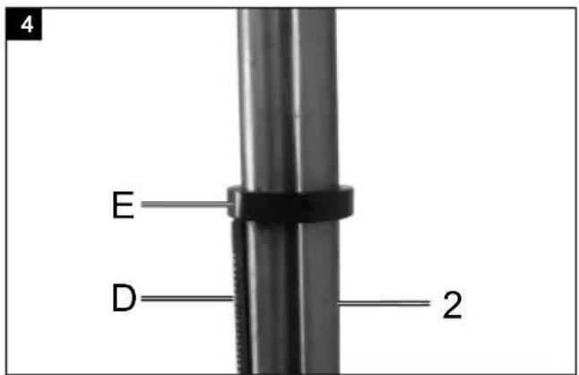
Removing the toothed rack, Fig. 4
In order to be able to install your drill, you must first remove the toothed rack (D).
-
Use an Allen key (WAF3) to remove the ring (E) and pull this off the column (2).
-
Now pull the toothed rack (D) out.
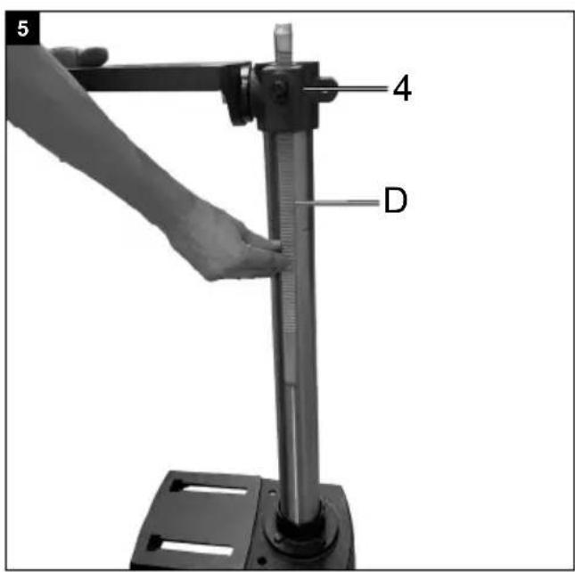
Installing the drilling table holder, Fig. 5 - 7
- Insert the toothed rack (D) into the groove on the drilling table holder (4).
- Align the toothed rack (D) centrally in relation to the drilling table holder (4).
- When bringing the toothed rack (D) together within the groove, ensure that the tooth meshing between the toothed rack and the drilling table holder (4) is correct.
-
Now place the drilling table holder (4) with the toothed rack (D) on the column (2) and guide the toothed rack (D) into the bottom rack guide on the column foot.
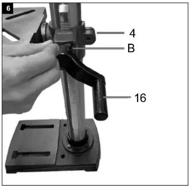
-
Use the ring (E) to secure the toothed rack (D). Ensure that the toothed rack guide on the ring (E) is pointing downwards. Tighten the integrated Allen screw to affix the ring (E).
- Place the crank handle (16) on the shaft of the drilling table holder (4) and secure it with the hexagon socket screw. Use the Allen key (B) for this purpose
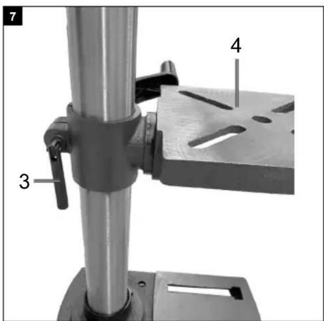
- Screw the clamping handle (3) into the drilling table holder (4).
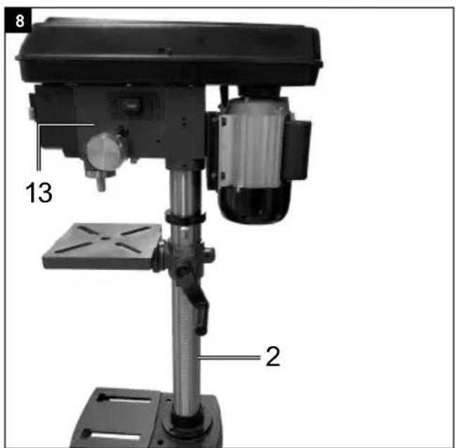
Installing the machine head and column, Fig. 8
- Place the machine head (13) on the column (2).
- Align the drill's spindle with the table and the base plate and tighten the Allen screw that is located on the side of the machine head. (Allen key WAF4 / A)
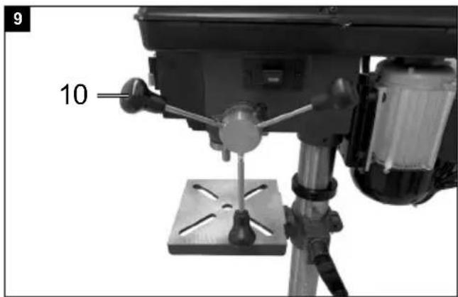
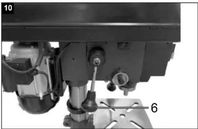
Installing the handle, Fig. 9+10
- Screw three handles (10) tight in the handle bracket's thread. Use the hexagon spanner to do this.
- Screw the remaining speed adjustment lever (handle) (6) into the handle bracket for speed adjustment. Use the hexagon spanner to do this.
Installing the folding swarf protector and the drill chuck, Fig. 11
- Push the folding swarf protector (11) onto the spindle on the machine head and use a Phillips head screwdriver to secure it.
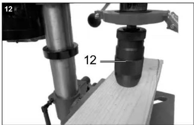
Installing the chuck, Fig. 12
- Clean the conical hole in the chuck and the spindle cone with a clean piece of fabric. Ensure that no particles of dirt remain on the surface. The smallest amount of contamination on one of the surfaces prevents the chuck holding properly. This can cause the drill bit to wobble. If the conical hole in the chuck is extremely contaminated, use a cleaning agent on a clean piece of fabric.
- Push the chuck onto the spindle lug as far as possible.
- Turn the outer ring on the chuck anti-clockwise (when viewed from above) and open the jaws on the chuck.
- Place a piece of wood on the machine table and lower the spindle until it touches the piece of wood. Press tight so that the chuck is secure.
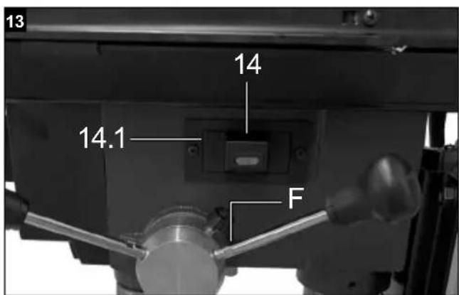
Inserting/replacing the battery: Laser operation Fig. 13
- Inserting/replacing the battery: Switch off the laser Insert or remove the battery compartment cover (14.1). Remove batteries and replace with new ones (2 AA batteries).
- Switching on: Move the laser on/off switch (14) to position "I" to switch on the laser. Two laser lines are projected onto the workpiece to be machined, the intersection of which indicates the centre of the drill tip.
- Switching off: Move the laser on/off switch (14) into the "0" position.
Setting the laser, Fig. 13
The laser can be adjusted using the adjusting screws (F).
Note: To protect against corrosion, all bare parts are heavily greased at the factory. Before placing the drill chuck (12) on the spindle, both parts must be made completely free of grease with an environmentally friendly solvent, so that optimal power transmission is guaranteed.
Setting up the machine
Prior to starting the machine, the drill must be mounted on a solid surface.
Therefore, use the two mounting holes in the base plate. Make sure that the machine is freely accessible for operation and for adjustment and maintenance work.
Note: The fastening screws must only be tightened so that the base plate is not strained or deformed. Risk of breakage in case of heavy loads.
Pay attention prior to commissioning
Make sure that the voltage of the mains connection matches the type plate. Only connect the machine to a socket with a properly installed protective contact. The drilling machine is equipped with a zero-voltage release, which protects the operator against unintentional restart after a voltage drop. In this case the machine must be switched on again.
9. Operation
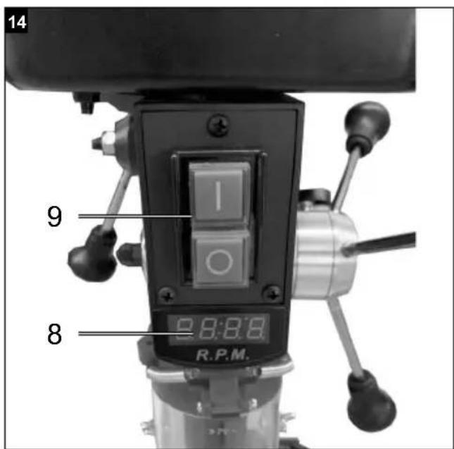
General, Fig. 14
To switch on, actuate the green on switch "I" (9), the machine starts. To switch off, press the red "O" button (9), the device switches off.
Ensure that you do not overload the device.
If the engine noise drops during operation, the engine is loaded too heavily.
Do not stress the device to the extent that engine is brought to a stop. Always stand in front of the machine during operation.
Inserting tool into chuck, Fig. 1
When replacing, ensure that the mains plug is pulled out. Only cylindrical tools with the specified maximum shaft diameter may be clamped in the chuck (12). Use only faultless and sharp tools. Do not use tools that are damaged on the shaft or that are otherwise deformed or damaged. For your own safety, only use accessories and additional equipment that are indicated in the operating manual or have been recommended or indicated by the manufacturer. If the column drilling machine blocks, switch off the machine and go back to the starting position with the drill.
Handling the quick-action drill chuck
The column drilling machine is equipped with a quick-action drill chuck. The tool can be changed without the aid of an additional chuck key, by inserting the tool into the quick-action drill chuck and by tightening it by hand.
Speed adjustment, Fig. 1
The speed of the machine can be continuously adjusted.
Attention!
- The speed may only be changed when the engine is running.
- Do not move the speed adjustment lever (6) suddenly, set the speed slowly and evenly while the machine is idling.
- Make sure that the machine can run freely (remove workpieces, drills, etc.).
The speed can be continuously adjusted using the speed adjustment lever (6). The defined speed is shown in turns per minute on the digital display (8).
Attention! Never let the drill run with the V-belt cover open. Always pull the mains plug before opening the cover. Never reach into running V-belts.
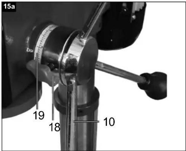
Drilling depth stop, Fig. 15a
The drill spindle has a rotatable scale ring (19) for setting the drilling depth. Only set up work while stopped.
- Press the drill spindle down until the drill tip lies on the workpiece.
- Loosen the clamping screw (18) and turn the scale ring (19) forwards until it stops.
- Turn the scale ring (19) back by the desired drilling depth and fix it with the clamping screw (18).
Attention! When setting the drilling depth of a cylindrical hole, you must add the length of the drill tip.
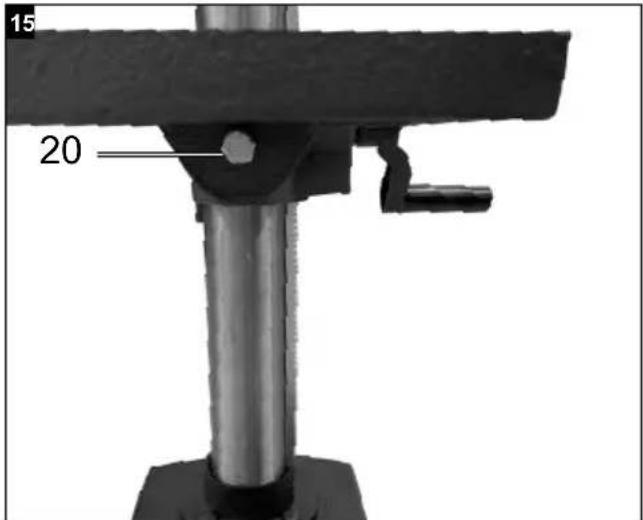
Setting the inclination of the drilling table, Fig. 1, 15
- Loosen the hexagonal bolt (20) under the drilling table (4).
- Set the drilling table (4) to the desired angle.
- Tighten the carriage bolt (20) again to fix the drilling table (4) in this position.
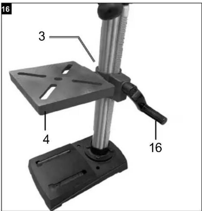
Setting the height of the drill table, Fig. 16
- Loosen the clamping screw (3).
- Move the drilling table to the desired position using the crank handle (16).
• Retighten the clamping screw (3).
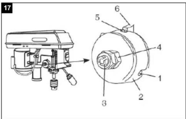
Setting the spindle return spring, Fig. 17
The spindle return spring may have to be set, as it's tension has changed and therefore, the spindle moves back too quickly or too slowly.
- Lower the table for more space to work.
- Work on the left of the drill.
-
Insert a screwdriver into the front groove (1) and keep this in position.
-
Use an open-ended spanner (size 14) to remove the outer nut (3)
-
With the screwdriver still in the groove, loosen the inner nut (4) until the notch releases from the hub (6). ATTENTION, springs are tensioned!
-
Turn the spring cap (2) carefully in an anti-clockwise direction using the screwdriver until you can press the groove (1) into the hub (6).
-
Lower the spindle into the lowest position and keep the spring cap (2) in position. Once the spindle moves up and down as you require, re-tighten the inner nut (4).
-
If it is too loose, repeat steps 3-5. If it is too tight, repeat step 6 in reverse order.
-
Use an open-ended spanner to secure the outer nut (3) against the inner nut (4).
-
NOTE: Do not over-turn and do not limit the range of movement of the spindle!
Axial play for the spindle, Fig. 18
When the spindle is in the bottom position, turn it manually. If you determine that the play is excessive, proceed as follows:
- Loosen the counternut (21).
-
Turn the screw (22) clockwise in order to compensate for the play without impairing the upwards and downwards movement for the spindle (a small amount of play is normal).
-
Re-tighten the counternut (21).
Tensioning the workpiece
Always clamp workpieces firmly using a machine vice or suitable clamping equipment. Never hold workpieces by hand! When drilling, the workpiece should be movable on the drilling table (4) so that self-centering can take place. Always secure the workpiece against twisting. The best way to do this is to place the workpiece or machine vice against a fixed stop.
Attention! Metal parts must be clamped so that they cannot be pulled up. Depending on the workpiece, correctly adjust the height and inclination. There must be enough distance between the top of the workpiece and the tip of the drill.
Working speed
Ensure correct speed during drilling. This depends on the drill diameter and the material.
The list below will help you choose speeds for different materials.
The speeds indicated are only guidelines.
| Drill diameter | Grey cast iron | Steal Iron | Aluminium Bronze | ||
| 3 | 2550 | 1600 | 2230 | 9500 | 8000 |
| 4 | 1900 | 1200 | 1680 | 7200 | 6000 |
| 5 | 1530 | 955 | 1340 | 5700 | 4800 |
| 6 | 1270 | 800 | 1100 | 4800 | 4000 |
| 7 | 1090 | 680 | 960 | 4100 | 3400 |
| 8 | 960 | 600 | 840 | 3600 | 3000 |
| 9 | 850 | 530 | 740 | 3200 | 2650 |
| 10 | 765 | 480 | 670 | 2860 | 2400 |
| 11 | 700 | 435 | 610 | 2600 | 2170 |
| 12 | 640 | 400 | 560 | 2400 | 2000 |
| 13 | 590 | 370 | 515 | 2200 | 1840 |
| 14 | 545 | 340 | 480 | 2000 | 1700 |
| 16 | 480 | 300 | 420 | 1800 | 1500 |
| 18 | 425 | 265 | 370 | 1600 | 1300 |
| 20 | 380 | 240 | 335 | 1400 | 1200 |
| 22 | 350 | 220 | 305 | 1300 | 1100 |
| 25 | 305 | 190 | 270 | 1150 | 950 |
Countersinking and pilot drilling
You can also use this tabletop drill for countersinking or centre drilling. Please note that countersinking should be carried out at the lowest speed, while a high speed is required for pilot drilling.
Woodworking
Please note that suitable dust extraction must be used when working with wood, as wood dust can be hazardous to health. Wear a mask when carrying out dust-creating work.
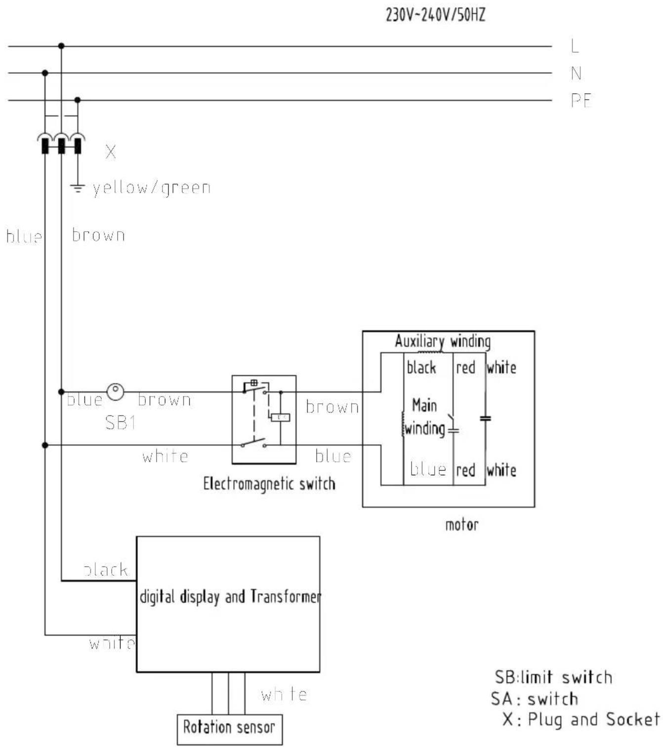
10. Electrical connection
The electrical motor installed is connected and ready for operation. The connection complies with the applicable VDE and DIN provisions. The customer's mains connection as well as the extension cable used must also comply with these regulations.
Important information
In the event of overloading, the motor will switch itself off. After a cool-down period (time varies) the motor can be switched back on again.
Damaged electrical connection cable
The insulation on electrical connection cables is often damaged.
This may have the following causes:
- Pressure points, where connection cables are passed through windows or doors.
- Kinks where the connection cable has been improperly fastened or routed.
- Places where the connection cables have been cut due to being driven over.
- Insulation damage due to being ripped out of the wall outlet.
- Cracks due to the insulation ageing.
Such damaged electrical connection cables must not be used and are life-threatening due to the insulation damage.
Check the electrical connection cables for damage regularly. Ensure that the connection cables are disconnected from electrical power when checking for damage.
Electrical connection cables must comply with the applicable VDE and DIN provisions. Only use connection cables with designation H05VV-F.
The printing of the type designation on the connection cable is mandatory.
Connection type Y
If the mains connection cable of this device is damaged, it must be replaced by the manufacturer, their service department or a similarly qualified person to avoid dangers.
AC motor
• The mains voltage must be 230 V\~
- Extension cables up to 25 m long must have a cross-section of 1.5 square millimetres.
Connections and repair work on the electrical equipment may only be carried out by electricians.
Please provide the following information in the event of any enquiries:
• Type of current for the motor
• Data of machine type plate
- Motor data - type plate
11. Cleaning and maintenance
Pull out the mains plug before carrying out any adjustments, maintenance or repair work.
△ Have tasks that are not described in this operating manual, carried out by a specialist workshop. Use only original parts. Let the device cool down before all maintenance and cleaning tasks. There is a risk of burns!
Before using the device each time, check the device for obvious defects such as worn or damaged parts, correct seating of screws or other parts. Replace damaged parts.
Cleaning
Do not use cleaning agents or solvents. Chemical substances could damage the plastic parts of the device. Never clean the device under running water.
- Clean the device thoroughly after each use.
- Clean the ventilation holes and the surface of the device with a soft brush or cloth.
- Remove chips, dust and dirt with a vacuum cleaner if necessary.
- Lubricate the moving parts regularly.
- Do not allow lubricants to get onto switches, V-belts, drive pulleys and drill stroke arms.
Service information
With this product, it is necessary to note that the following parts are subject to natural or usage-related wear, or that the following parts are required as consumables.
Wearing parts*: V-belt, drill, battery
* may not be included in the scope of supply!
Spare parts and accessories can be obtained from our service centre. To do this, scan the QR code on the cover page.
12. Storage
Store the device and its accessories in a dark, dry and frost-free place that is inaccessible to children.
The optimum storage temperature lies between 5 and 30 °C.
Store the power tool in its original packaging.
Cover the electric tool to protect it from dust or moisture.
Store the operating manual with the power tool.
13. Disposal and recycling
Notes for packaging


The packaging materials are recyclable. Please dispose of packaging in an environmentally friendly manner.
Notes on the electrical and electronic equipment act [ElektroG]
![SCHEPPACH DP19Vario - Notes on the electrical and electronic equipment act [ElektroG] - 1](/content/2026/03/573631/images/84ea0f94c897d69746ed856449a2cdc194e37ab0a3a60f9d9b860ac572b8b3e1.jpg)
Waste electrical and electronic equipment does not belong in household waste, but must be collected and disposed of separately!
- Used batteries or rechargeable batteries that are not installed permanently in the old appliance must be removed non-destructively before disposal. Their disposal is regulated by the battery law.
- Owners or users of electrical and electronic devices are legally obliged to return them after use.
- The end user is responsible for deleting their personal data from the old device being disposed of!
- The symbol of the crossed-out dustbin means that waste electrical and electronic equipment must not be disposed of with household waste.
- Waste electrical and electronic equipment can be handed in free of charge at the following places:
- Public disposal or collection points (e.g. municipal works yards)
- Points of sale of electrical appliances (stationary and online), provided that dealers are obliged to take them back or offer to do so voluntarily.
- Up to three waste electrical devices per type of device, with an edge length of no more than 25 centimetres, can be returned free of charge to the manufacturer without prior purchase of a new device from the manufacturer or taken to another authorised collection point in your vicinity.
- Further supplementary take-back conditions of the manufacturers and distributors can be obtained from the respective customer service.
- If the manufacturer delivers a new electrical appliance to a private household, the manufacturer can arrange for the free collection of the old electrical appliance upon request from the end user. Please contact the manufacturer's customer service for this.
- These statements only apply to devices installed and sold in the countries of the European Union and which are subject to the European Directive 2012/19/EU. In countries outside the European Union, different regulations may apply to the disposal of waste electrical and electronic equipment.
Information on the battery act [BattG]
![SCHEPPACH DP19Vario - Information on the battery act [BattG] - 1](/content/2026/03/573631/images/8183a2d25dda45959ecb63481e1a40a68686c08908932268f0f637dad76a0e2e.jpg)
Old batteries and rechargeable batteries do not belong in household waste, but must be collected or disposed of separately!
- For safe removal of primary batteries or rechargeable batteries from the electrical appliance and for information on their type or chemical system, please refer to the additional information in the operating or assembly instructions.
- Owners or users of primary batteries and rechargeable batteries are legally obliged to return them after use. The return is limited to household quantities.
- Old batteries may contain pollutants or heavy metals that can harm the environment or human health. Recycling old batteries and using the resources they contain helps to protect these two important issues.
- The symbol of the crossed-out dustbin means that primary batteries and rechargeable batteries must not be disposed of with household waste.
- If the signs Hg, Cd or Pb are also located below the dustbin symbol, this stands for the following:
- Hg: Battery contains more than 0.0005% mercury
- Cd: Battery contains more than 0.002% cadmium
- Pb: Battery contains more than 0.004% lead
- Rechargeable batteries and primary batteries can be returned free of charge to the following places:
- Public disposal or collection points (e.g. municipal works yards)
- Sales points for primary batteries and rechargeable batteries
- Take-back points of the common take-back system for old device batteries
- Take-back point of the manufacturer (if not a member of the common take-back system)
- These statements are only valid for rechargeable batteries and primary batteries sold in the countries of the European Union and subject to the European Directive 2006/66/EC. In countries outside the European Union, different regulations may apply to the disposal of rechargeable batteries and primary batteries.
14. Troubleshooting
Warning:
Switch the machine OFF and remove the mains plug from the power outlet.
| Fault Problem Solution | ||
| The axis returns to its starting position too quickly or too slowly | Spring tension is set incorrectly. Setting the spring tension, see also "Spindle return spring". | |
| The chuck keeps loosening from the spindle despite being reattached. | Dirt, grease or oil on the spindle or on the inside of the chuck. | Use a household detergent to clean the surface of the spindle and drill chuck. See also "Installing the drill chuck" |
| Strong noise development during operation | Wrong V-belt tension. Set the V-belt tension. See also "Setting the speed and V-belt tension". | |
| The spindle is too dry. Test the spindle. See also "Lubrication". | ||
| Pulley on the spindle is loose. | Check the nut on the pulley for firm seating and tighten it if necessary. | |
| Pulley on the motor is loose. | Tighten the set screw on the motor pulley. | |
| Wood splinters at the opening of the drill | No suitable base under the workpiece. | Use a suitable and stable base. See also "Adjusting the table and the workpiece". |
| The workpiece snaps out of your hand. | No suitable base under the workpiece or not firmly fixed. | Reline the workpiece or fasten it. |
| The drill anneals. | Wrong speed. | Change the speed. See also "Setting the speed and V-belt tension". |
| No chips come out of the borehole. | Regularly drive the drill out of the drill hole to remove the chips. | |
| Blunt drill. | Sharpen the drill. | |
| Feed too low. | Increase the feed. | |
| The drill is running or the hole is out of centre | Hard areas in the wood or the length and angle of the drill bit is different. | Sharpen the drill. |
| Drill is bent. Exchange the drill. | ||
| The drill blocks the workpiece. Workpiece | ce and drill are tilted or speed is too high. | Reline the workpiece or fix it. See also “Position the workpiece” |
| Inadequate V-belt tension | Set the V-belt tension. See also “Setting of the speed and V-belt tension”. | |
| Excessive run and wobbling of the drill | Bent drill. Use a straight drill. | |
| Excessive wear on the spindle bearings. | Replace the spindle bearing. | |
| The drill is not centred in the chuck. Check the centering. See also “Setting the drill” | ||
| Chuck is not firmly fixed. Correctly fix the chuck. See also “Installing the drill chuck” | ||
Günzburger Straße 69
D-89335 Ichenhausen
Cher client,
Günzburger Straße 69
D-89335 Ichenhausen
Egregio cliente,
Günzburger Straße 69
D-89335 Ichenhausen
Geachte klant,
Günzburger Straße 69
D-89335 Ichenhausen
Estimado cliente:
Günzburger Straße 69
D-89335 Ichenhausen
Estimado cliente,
Günzburger Straße 69
D-89335 Ichenhausen
Vážený zákazníku,
Günzburger Straße 69
D-89335 Ichenhausen
Vážený zákazník,
Günzburger Straße 69
D-89335 Ichenhausen
Kedves Ügyfelünk!
Günzburger Straße 69
D-89335 Ichenhausen
Szanowny Kliencie,
Günzburger Straße 69
D-89335 Ichenhausen
Poštovani kupci,
Prikladnim mjerama opreza zaštitite sebe i svoju okolinu od opasnosti od nezgode!
Günzburger Straße 69
D-89335 Ichenhausen
Spoštovani kupec,
želimo vam veliko veselja in uspeha pri delu z vašo novo napravo.
Napotek:
Günzburger Straße 69
D-89335 Ichenhausen
Austatud klient!
Günzburger Straße 69
D-89335 Ichenhausen
Gerbiamas kliente,
Günzburger Straße 69
D-89335 Ichenhausen
Godātais klient!
Günzburger Straße 69
D-89335 Ichenhausen
Bästa Kund!
Günzburger Straße 69
D-89335 Ichenhausen
Arvoisa asiakas
Günzburger Straße 69
D-89335 Ichenhausen
Kære kunde,
EC Declaration of Conformity
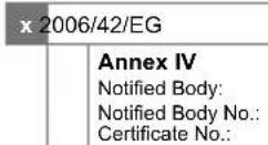
| 2016/1628/EU |
| Emission. No: |
Standard references:
EN 62841-1:2015; EN 62841-3-13:2017; EN 55014-1:2017; EN 55014-2:2015; EN IEC 61000-3-2:2019; EN 61000-3-3:2013+A1:2019
This declaration of conformity is issued under the sole responsibility of the manufacturer.
The object of the declaration described above fulfils the regulations of the directive 2011/65/EU of the European Parliament and Council from 8th June 2011, on the restriction of the use of certain hazardous substances in electrical and electronic equipment.
Subject to change without notice
Documents registrar: Ann-Katrin Bloching
Günzburger Str. 69, D-89335 Ichenhausen
EC Declaration of Conformity
Article name: Bench drill - DP19VARIO
Nom d'article:
Standard references:
EN 62841-1:2015; EN 62841-3-13:2017; EN 55014-1:2017; EN 55014-2:2015; EN IEC 61000-3-2:2019; EN 61000-3-3:2013+A1:2019
This declaration of conformity is issued under the sole responsibility of the manufacturer.
The object of the declaration described above fulfils the regulations of the directive 2011/65/EU of the European Parliament and Council from 8th June 2011, on the restriction of the use of certain hazardous substances in electrical and electronic equipment.
EC Declaration of Conformity
Article name: Bench drill - DP19VARIO
Nom d'article:
Standard references:
EN 62841-1:2015; EN 62841-3-13:2017; EN 55014-1:2017; EN 55014-2:2015; EN IEC 61000-3-2:2019; EN 61000-3-3:2013+A1:2019
The object of the declaration described above fulfils the regulations of the directive 2011/65/EU of the European Parliament and Council from 8th June 2011, on the restriction of the use of certain hazardous substances in electrical and electronic equipment.
Subject to change without notice
Documents registrar: Ann-Katrin Bloching
Günzburger Str. 69, D-89335 Ichenhausen
Garantie DE
Apparent defects must be notified within 8 days from the receipt of the goods. Otherwise, the buyer's rights of claim due to such defects are invalidated. We guarantee for our machines in case of proper treatment for the time of the statutory warranty period from delivery in such a way that we replace any machine part free of charge which provably becomes unusable due to faulty material or defects of fabrication within such period of time. With respect to parts not manufactured by us we only warrant insofar as we are entitled to warranty claims against the upstream suppliers. The costs for the installation of the new parts shall be borne by the buyer. The cancellation of sale or the reduction of purchase price as well as any other claims for damages shall be excluded.
Garantie FR
Apparent defects must be notified within 8 days from the receipt of the goods. Otherwise, the buyer's rights of claim due to such defects are invalidated. We guarantee for our machines in case of proper treatment for the time of the statutory warranty period from delivery in such a way that we replace any machine part free of charge which provably becomes unusable due to faulty material or defects of fabrication within such period of time. With respect to parts not manufactured by us we only warrant insofar as we are entitled to warranty claims against the upstream suppliers. The costs for the installation of the new parts shall be borne by the buyer. The cancellation of sale or the reduction of purchase price as well as any other claims for damages shall be excluded.
Záruka CZ
Apparent defects must be notified within 8 days from the receipt of the goods. Otherwise, the buyer's rights of claim due to such defects are invalidated. We guarantee for our machines in case of proper treatment for the time of the statutory warranty period from delivery in such a way that we replace any machine part free of charge which provably becomes unusable due to faulty material or defects of fabrication within such period of time. With respect to parts not manufactured by us we only warrant insofar as we are entitled to warranty claims against the upstream suppliers. The costs for the installation of the new parts shall be borne by the buyer. The cancellation of sale or the reduction of purchase price as well as any other claims for damages shall be excluded.