
Cuddy DC II - Air Conditioning DOMETIC - Free user manual and instructions
Find the device manual for free Cuddy DC II DOMETIC in PDF.
| Product type | Self-contained marine air conditioning |
| Brand | Dometic |
| Model | Cuddy DC II |
| Cooling capacities | 6,000, 8,000, 12,000, 16,000, 20,000 BTU/h |
| Power supply | 230 V AC / 24 V DC (depending on model) |
| Refrigerant type | R32 (flammable) |
| Minimum seawater temperature | 4.4 °C (40 °F) |
| Maximum seawater temperature | 32.2 °C (90 °F) |
| Minimum seawater pressure | 4.5 psi (0.31 bar) |
| Maximum seawater pressure | 60 psi (4.14 bar) |
| Approximate dimensions (L x W x H) | 400 x 300 x 250 mm (depending on model) |
| Approximate weight | 25 to 35 kg depending on model |
| Application | Boats and yachts |
| Main functions | Cooling, heating (reversible models) |
| Maintenance and cleaning | Regular cleaning of air filter, condensate draining, maintenance of seawater circuit |
| Safety | Dedicated circuit breaker, grounding, prevention of flammable refrigerant leaks |
| Spare parts and repairability | Air filter, seawater pump, electrical parts available from Dometic |
| Warranty | 2 years (depending on region) |
| General information | Installation by a qualified professional, compliance with local regulations |
Frequently Asked Questions - Cuddy DC II DOMETIC
User questions about Cuddy DC II DOMETIC
0 question about this device. Answer the ones you know or ask your own.
Ask a new question about this device
Download the instructions for your Air Conditioning in PDF format for free! Find your manual Cuddy DC II - DOMETIC and take your electronic device back in hand. On this page are published all the documents necessary for the use of your device. Cuddy DC II by DOMETIC.
USER MANUAL Cuddy DC II DOMETIC
Cancer and Reproductive Harm
www.P65Warnings.ca.gov
DCU, DLU, DTG, ECD, GT, GTX, GTX-LP, GVTX, TX
EN Self-Contained Air Conditioning System Installation Manual.
DE Self-Contained Air Conditioning System Montageanleitung.
Self-Contained Air Conditioning System Instructions de montage 20
ES Self-Contained Air Conditioning System Instrucciones de montaje. 2T
PT Self-Contained Air Conditioning System Instruções de montagem. MS
Self-Contained Air Conditioning System Indicazioni di montaggio. 4R
Self-Contained Air Conditioning System Montagehandleiding. PQ
DA Self-Contained Air Conditioning System Monteringsvejledning.
Self-Contained Air Conditioning System Monteringsanvising. R4
NO Self-Contained Air Conditioning System Monteringsanvising. S2
Self-Contained Air Conditioning System Asennusohje.
PL Self-Contained Air Conditioning System Instrukcja montaizu.. TS
SK Návod na montáž. 0R
CS Self-Contained Air Conditioning System Navod k monta zi
HU Self-Contained Air Conditioning System! zere!"si utmutato. 2P
Self-Contained Air Conditioning System Upute za montažu.
T Self-Contained Air Conditioning System Montaj' (lavuzu.
SL Self-Contained Air Conditioning System Navodilo za montažo.
Self-Contained Air Conditioning System Instrui de montaj..
Self-Contained Air Conditioning System
INH, - /01234567H-58............JGS
ET Self-Contained Air Conditioning System 9aigaldusjuhend.
EL Self-Contained Air Conditioning System O#r#tioe tono#
Self-Contained Air Conditioning System Montavimo vadovas.
Self-Contained Air Conditioning System Uzst: d'sanas rokasgr: mata. 202
Copyright' t
© 2024 Aometric Broup. Che visual appearance of the contents of this manual is protected EF copFright and design laG. Che underFing technical design and the products contained herein maF Ee protected EF design patent or pending patent. Che trademarks mentioned in this manual Eelong to Aometric! Geden Al . All rights are reserved.
Englis
Important notes.
2 KLplanation oSfMEols.
M Carget group's 4
4 Intended use. 4
P KLplanation oSfMEns on the device. 4
Q9pre-installation 4
R Installation.
SAisposal.
T Technical data.
J0Legal.
VarrantF
Important notes
Slose read these instructions corelll am vHg all inscrfions guidelines am Gannings indel this product manual in order to ensure that Fou install use and maintain the product proper at all times. Cheise instructions MUC sfaf Gith this product.
Fusing the product-Fou hereE confirm that Fou have read all instructions guidelines and Gannings careill and that Fou understand and agree to all the terms and conditions as set forth herein. Xun agrees to use this product only for the intended purpose and application and in accordance with the instructions guidelines and Gannings as set forth in this product manual. Ce as in accordance Ghth all applicable Ia cks and regulations. A failure to read and folioe the instructions and Gannings set forth herein result in an injury to yourself and other damage to your product or otherwise property in the vicinity. This product manuall including the instructions guidelines and Ganningsl and related documentation may eae suject to changes and updates. You up-to-date product information please visit documents.banfier.com.
2 Explanation of sym, ols
A signal Gord Gill identifF safetF messages and propertF damage messages and also Gill indicate the degree or level of hazard seriousness.

DANGE - Indicates a hazardous situation that I not avoided. Gill result in death or serious injurf.

A NING- Indicates a hazardous situation that not avoided could result in death or serious injurf.

NOTICE- Indicates a situation that it not avoided can result in propertF damage.

NOTE! upplementarF information for operating the product.
2/) S0plementale dire1ti2es
Co reduce the risk of accidents and injuries please oEserve the rolloGing directives Eelore proceeding to install this appliance?
Read and rolgo all saetF information and instructions.
Read and understand these instructions Before installing this product.
[ Che installation must complF Gith all applicaEle local or national codes- including the latest edition of the rolloGing standards]
[ American I oat and Xacht] oculir [Al X] 3
[AN!I/NY9AR0-NationalKlectrical]odeNK]
2/2 Safety instr01tions

DANGE - is3 of fire or explosion/ Some models 0se flamma, le refrigerant/
Yailure to oEeF the olloGing Garnings Gill result in death or serious injurF > Co Ee repaired onlEF trained service personnel.
Ao not install or store in a location Gith continuousF operating sources of ignition.
Maintain all required ventilation openings free from oEstructions.
Ao not puncture frigerant tuEing.
Refer to the product data plate for refrigerant tFpe.

A NING- Fire and4or explosion a5ard
Failure to oEef the JolloGing Garnings could result in death or serious injurF?
Ao not use potential sources of ignition to detect or search for refrigerant leaks. Ao not use a halide torch or anF other detector that uses a naked flame.
e sure that detection equipment is suitaEle for the refrigerant tfpe used in the product. Refer to the product data plate for the refrigerant tfpe.
Electronic leak detectors maF Ee used to detect reigrant leaks hoGever their sensitivf maF Ee inadequate or flammaEle reigrants and maF need recalIeration.]aliErate detection equipment in a reigrant-ree area.

A NING-Car, on monoxide a5ard Failure to oEeF the JolloGing Garnings could result in death or serious injurF
Ao not install or operate a self-contained air conditioner in the Eilge or engine room areas or near an internal comEustion engine. Knows that the selected location is sealed from direct access to Eilge and/or engine room vapors.
aeriF the condensate drain line is properIF installed and sealed. A not end the condensate drain line Githin b, 00.T] m0 anF outlet o) an engine or generator elhaust sFstem in a compartment containing an engine or generator or in a Eilge unless the drain is connected properIF to a sealed condensate or shoGer sump pump. If the drain line is not properIF installed dangerous fumes maF travel up the drain line and contaminate the living quarters.
Ao not install the air conditioner in a location Ghere it can circulate carEon monoLideH fuel vaporsh or other noLiouss tumes into the Eoats living spaces.

A NING-Ele1tro10tion 'a5ard Che installation maF onlE Ee carried out EF a qualiied electrician.

. A NING-Eletrilal s' o13, fire and4or explosion ' a5ard
Yailure to IolloG these precautions could result in death or serious injurF.
This appliance is not intended for use EF persons including children. Gith reduced phFiscalH sensorH or mental capAElities; or lack of elExperience and knoGledgeH unless theF have Eeen given supervision or instruction eOut the use of the appliance EF a person responsiEle for their saetF.] children should Ee supervised to ensure that theF do not plaF Gith the appliance.] leaning and user maintenance shall not Ee made EF children Githout supervision. This appliance should not Ee accessiEle to the general puElic.

A NING- Explosion a5ard
Yailure to lolloG these precautions could result in death or serious injurF.
Ao not install the air conditioner in a location containing gasoline engines tanks 9B/198 cFlindersl regulatorsl valves or fuel line Wtings.Unless laEeled otherGiseh sel-contained units do not meet federal requirements for ignition protection. Yailure to oEeF this Garning could result in death or serious injurF.
Electrical components that can arc or spark shall onlF Ee replaced Gith parts specified EF the appliance manufacturer. Replacement Gith other parts maf result in the ignition of refrigerant in the event of a leak.
EN

A NING-EleIriIaS'o13'a5ard
Failure to JolloG these precautions could result in death or serious injurF.
I e sure to electively ground the air conditioner to minimize the electrical shock hazard. Refer to the installation guidelines for further information.
Kach air conditioner installed requires a dedicated circuit Ereaker. D there is onl one air conditioner installed the seaGater pump does not require a dedicated circuit Ereaker. D tGo or more air conditioning units use the same seaGater pump the pump Gires Gill Ee connected to a pump relaF panel 9R90- Ghich in turn has its oGn dedicated circuit Ereaker sized for the pump 20 A maL. Reier to the Giring diagramurnished Gith the 9R9. K electrical connections in the Elge and/or EeloG the Gaterline should use heat shrink Fpe Eutt splices.
Yield Giring must complFithGith AIX] electrical codes.9oGer to the unit must Ee Githin the operating voltage range indicated on the data plate. Properf sized uses or eA] R circuit Erakers must Ee installed for Eranch circuit protection.1e the data plate for the maximum use/circuit Eraker sizeMY and minimum circuit capacitIM] A.

NOTICE
This appliance has fluorinated greenhouse gases in hermetical sealed equipment. Refer to the condensing units product data plate laEel for the quantitF of refrigerant shOgIn in Geeight and BV 9. The refrigerant added should be noted on the unit laEel.

NOTICE-
Ao not use the copper tuEing to pushH pullH libH or carrF the product.
6 Target groOp7s8

Che mechanical and electrical installation and setup o the device must Ee performed EF a qualified technician Gho has demonstrated skill and knoGledge related to the construction and operation of marine equipment and installations and Gho is familiar Gith the applicaEle regulations of the counf in Ghich the equipment is to Ee installed and/or used- and has received saet training to identif and avoid the hazards involved.
9 Intended 0se
This manual is intended for the installation of A] UAUACB+K] ABCHCfHBCf- BAcf+ and cf sel-contained air conditioning sFstems whereinabere referred to as air conditioner. The air conditioner is intended for use on Eoats and Fachts. This air conditioner is onlf suiteAe for the intended purpose and application in accordance Gith these instructions.
This product is onlf suiteEle for the intended purpose and application in accordance with these instructions.
This manual provides information that is necessary for proper installation and/or operation of the product. Poor installation and/or improper operation or maintenance will result in unsatisfactory performance and a possible failure.
Che manufacturer accepts no liaEilitF lor anF injurF or damage to the product resulting from
Incorrect installation;assemEIF or connection including elcess voltage
Incorrect maintenance or use of spare parts other than original spare parts provided EF the manufacturer
[ Alterations to the product Githout eLpress permission from the manufacturer
[Use]or purposes other than those descriEed in this manual
Aometric reserves the right to change product appearance and product specifications.
Explanation of sym, ols on t'e de2i1e

V aming3 Risk of 're / YlammaEle materials

V arning LoG Eurning velocitF material. YlammaEle reRigerant.
Refrigerant salaf group A2J

Read operating manual.

Read service manual.
6 Pre-installation

NOTICE
Che ACB BCF BaCFI and CF self-contained condensate Ease pans are equipped Gith viEration isolators installed in the Bottom of the pan. These isolators are designed to dampen the viEration caused EF the operating air conditioner from transferring into the mounted surface.]are must Ee taken Chen moving the air conditioner across mounting surfaces as the isolators can Ee damaged.

NOTICE
Che air conditioner must Ee mounted to a loC+ flat level surface like in the Bottom of a locker under a Eunk or dinette seat or in a similar location.
Knsure that the caEling Gill not Ee suEject to Gearl corrosion elceissive pressure viEration sharp edges or another adverse environmental.
edctsl including eects from aging or continual viEration trom sources such as compressors or fans.
Knsure that protection devices: piping and wetings are protected as far as possiElec against adverse environmental effect such as dirt and deEris accumulation or Cater collecting and freezing in relief pipes.
Precautions should be taken to avoid excessive vEration or pulsation to the refrigerating piping.
6/ Determining t' e installation lo1ation
J. BaCf and Cf placement relative to airfloG
)00inR.02cm
9 4.00inJ0JQcm
2 e eat sink: Return air grille
61ulkhead 6 AirloG
All other air conditioning units placement relative to airfloG
4.00inOJGcm
9 M.00 in RQ2 cm
2 Return air grille: Iulkhead
6 AirloG
- I choose a location Gith enough airfoG. Che return air grille should have a minimum of 4.00 in 0J Cm of air circulation clearance in front of its free from an EoEstruction.
M. ID the air conditioner is positioned perpendicular to the return air grille maintain a minimum of M.00 in RQ2 cm air circulation clearance on the air intake side. - GVTX and TX only: Provide a minimum open area of 0.00 in R.O2 cm³ aEove and EeloG the heat sink.
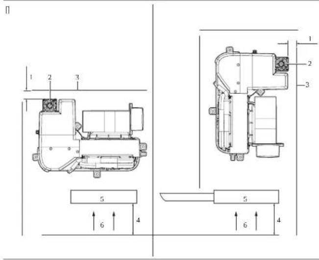
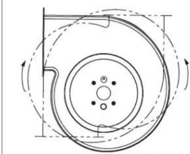
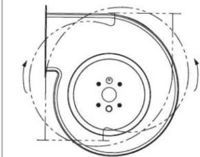
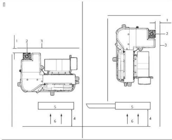
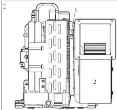
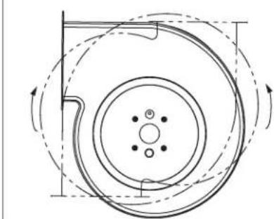
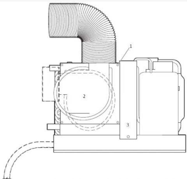
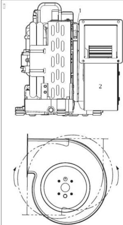
6/2 otating t' e, lower
This section elpains hoG to rotate the EloGer for each unit tFpe. It needed to rotate the EloGer to the direction that alloGs the most direct airfloG discharge through the ducting.
6/2/) GTX, GVTX, DTG, and TX, lowers
BCf+BaCf+ACB+and Cf sFstem EloGer rotation
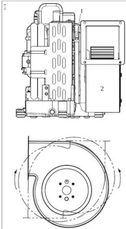
Adjustment screG
2 | LoGer
loosen the adjustment screG on the EloGer mount ring.
2. Rotate the EloGer to the desired position.
M. Cighten the adjustment screG.
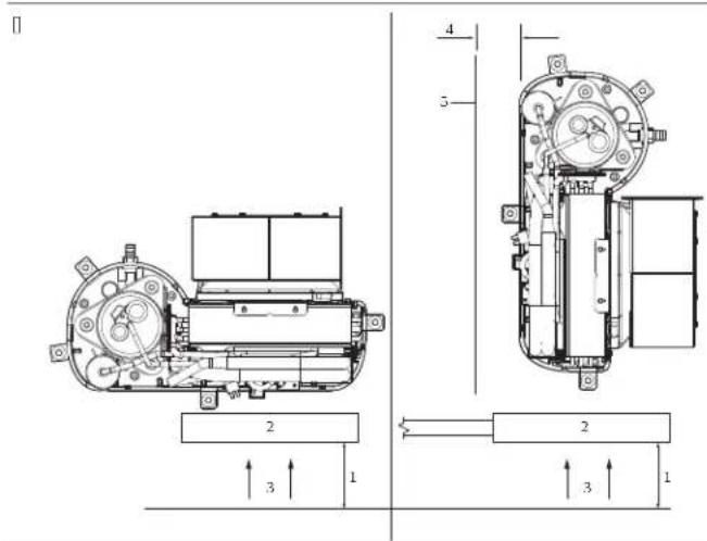
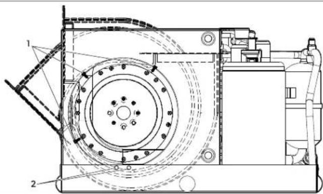
6/2/2 MCS, ECD and GT, lowers
M]HK] AH and BC sFstem EIoGer rotation
EN
#

)!creG
29late
61LoGer
- Remove the seven screwGs on the plate.
- Rotate the EloGer to the desired position.
M. I ecure the EloGer in place using sel-tapping screGs not provided.
6/2/6 DCU, lower
A] Usfstem EloGer rotation
#
1 creGs on EloGer ring
2!creGs on drain pan or Bracket
J. Remove the screGs from the EloGer ring.
2. Remove the screGs attaching the EloGer to the drain pan or Eracket.
M. Rotate the EloGer to the desired position.
4. Iecure the EloGer in place using self-tapping screGs (not provided).
P. Slug anF unused holes to prevent air loss.
6/6 Plaing t' e air filters
Air alters remove airborne particles from the caEin air and keep the evaporator coil clean. Place one air alter either on the air conditioner or in the return air grille for each air conditioner.
6/9 Plaing t' e grilles and transition, oxes
] onsider the JolloGing Ghen placing the grilles and transition EoLes
Install the suppF air grille as high as possEle in a location that Gill give uniform air distriEution throughout the caEin. Airect the grille louvers upGard.
Install the return air grille as loG and close to the air conditioner as possiEle to ensure airfloG to the evaporator.
[ Ao not direct the suppIF air discharge toGards the return air grill as this Gill cause the sFstem to short cfcle.
[AlloG or adequate clearance Eehind the suppl air grille lor the transition Eol and ducting connection. Refer to! peciWcations on page 10
7 Installation

A NING-EleItro10tion a5ard
Che installation maF onlFEe carried out EF a qualiWed electrician.
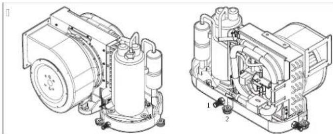
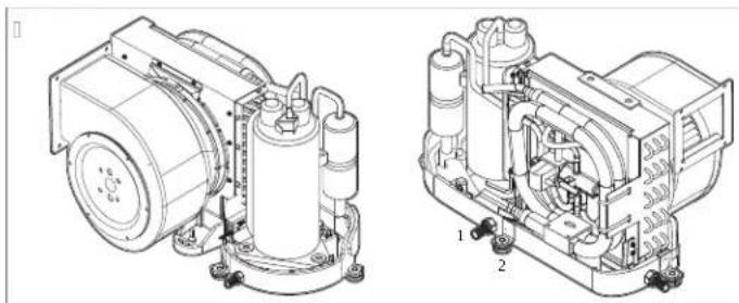
7/) Installing t' e moOnting, ra13ets and Iondensate drain

NOTICE
Co prevent cracking the drain pan do not use more than tGo laFers o
plumEers tape to Grap the hose EarE+ and do not overtighten the hose EarE.
CFpical placement of mounting Erackets and condensate drains
#
1ondensate drain hose EarE
2 Mounting Eracket
]ondensate drain installation for BCF + BaCF + ACB and Cf
eoseEae9Arain pan
2 Threaded drain hole: Arain hose
6! lug knockout
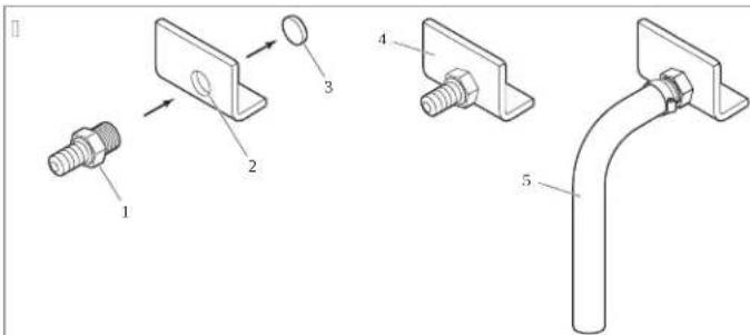
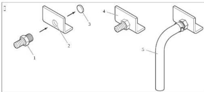
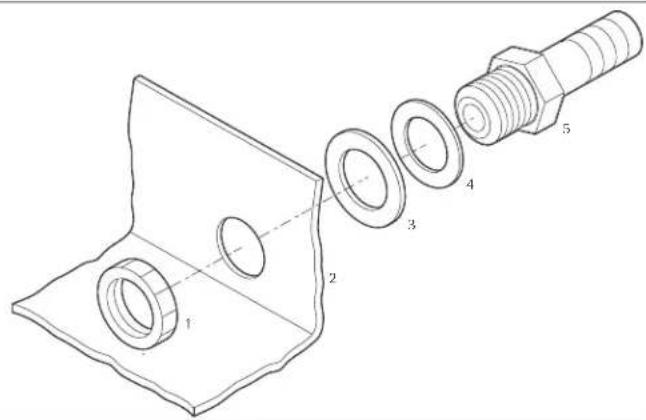
]ondensate drain installation for all other air conditioning units
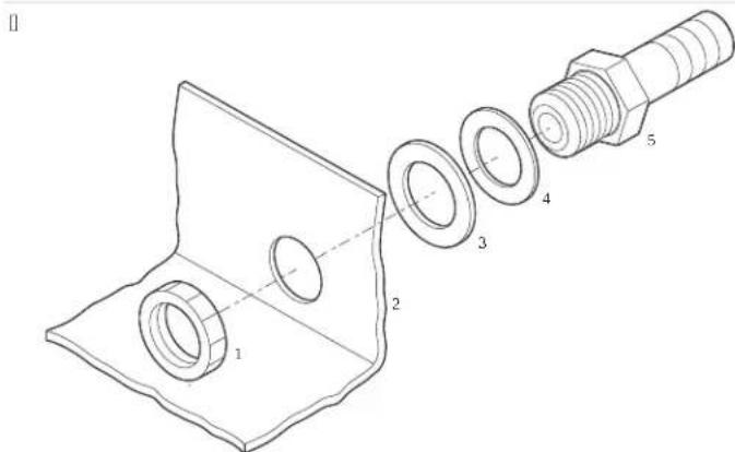
) Locking nut 9 !olid Gasher
2 Arain pan
9a]fiting0Pin2.RmmC1L0P in 2.RmmM9Cl
6 Liquid-seal Gasher
I.YorBCf+BaCf+ACBand Cf units
a5 Use the small end of the hose EarE to knock out a slug from an ab-facing drain hole EF applFing one quick strike Gith a rEEer mallet. Aiscard the slug knockout.
EV rap the threaded end of the hose EarE Gith plumErs tape.
ci creG the hose EarE into the threaded drain hole and tighten secureF.
- Yor all other air conditioners?
a) Thread the hose EarE through a solid Gasher and liquid-seal Gasher and insert it into the drain hole.
E0!ecureGithalockingnut.
M. I ecure the drain hose to the hose EarE Gith a stainless steel hose clamp.
- Route the drain hose doGnGard to a sale and proper collection point.
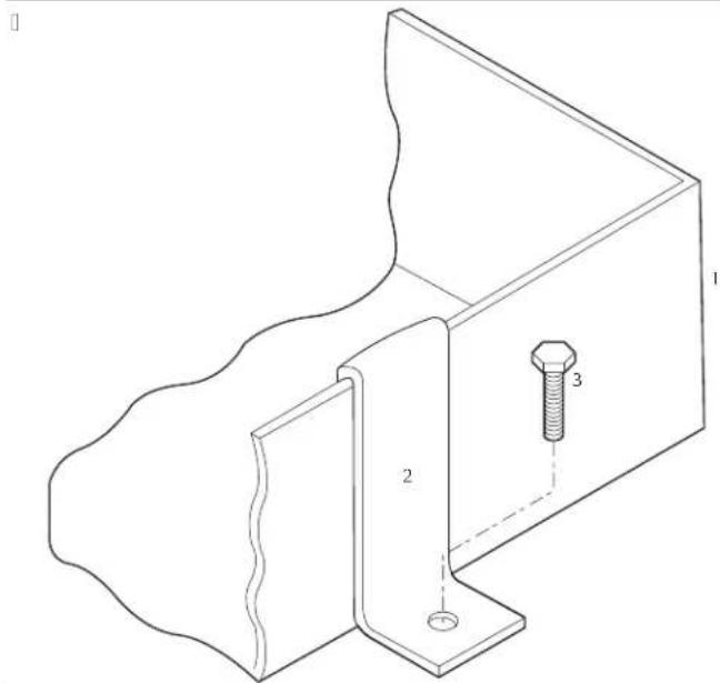
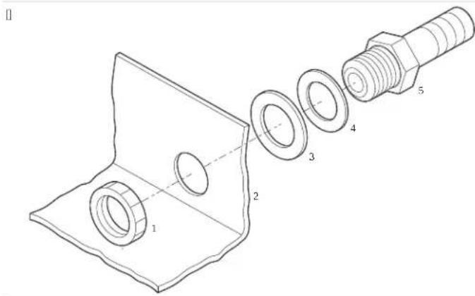
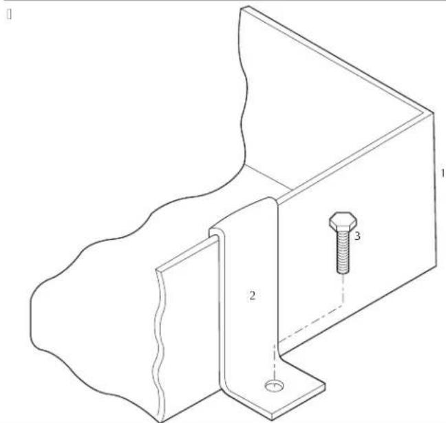
Mounting Eracket installation for B Cf H BaCf H ACB+ and Cf units

Mounting Eolt not provided.
2YenderGasher provided
6 Mounting Bracket provided
Mounting Fracket installation for other air conditioning units
Arain pan
2 Mounting Eracket
6 MountingOLTnot provided
EN
P. Install one mounting Eracket on each side of the drain pan even if spaced.
Installing loam handle insulation on BaCf and Cf units
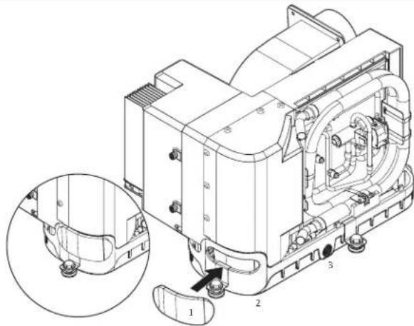
Yoam handle insulation
2 e andle opening
6 Arain pan
G. Yor BaCf and Cf units?
a Remove the film covering the adhesive Eacking on the loam handle insulation.
E9 Position the foam handle insulation to completely cover the handle opening Gith the adhesive side facing the drain pan.
Gress around the handle opening to adhere the foam handle insulation to the drain pan.
7/2 Installing t' e d01ting

A NING- is3 of fire or explosion
AuLiliF devices Ghich maF Ee ignition sources shall not Ee installed in the ductGorkh other than auLiliart devices listed for use Gith the specifc appliance.
Yor models using flammaEle refrigerantsH Ghich are connected via an air duct sstem to one or more rooms the supplF and return air shall Ee directF ducted to the space. h pen areas such as false ceilings shall not Ee used as a return air duct.
Ao not route ducting through an engine room or anF area Ghere it maF Ee elposed to dangerous vapors or eLhaust lumes.
h Eserve the rolloGing conditions Ghen installing the ducting?
[Aucting must Ee appropriate] sized for Four application.
[ Run ducting as straight smooth and taut as possiEle minimizing the numEer of T0] Eends and loopsGwhich can reduce airfloG.
Yasten the ducting secureIf to prevent sagging.
[ Ao not alloG ducting to Ee flattened or kinked.
[CrimeLcess ducting lengths JolloGing installation.
[ Insulate ducting Chen it is located in high-heat areas.
If a transition EoL is used the total area of suppF air ducts going out of the EoL should Ee at least equal to the total area of the suppF ducts going into the EoL. Refer to 1 peplicaions on page 0
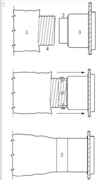
Aucting connections
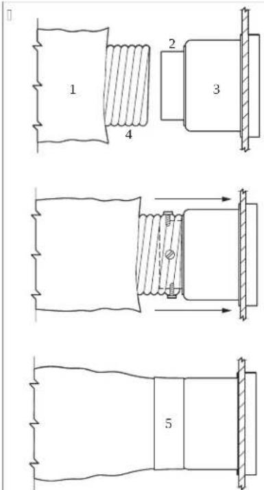
YiFerglass insulation 9 Inner mFlar duct hose
2 Mount ring: Auct tape
6 Transition EoL
.1 lide the inner mFlar duct hose around the mount ring to the transition EoL.
2.1 creG three or four stainless steel screGs through the mFlar duct hose into the mount ring capturing tGo or three Gires Gith screG heads.
M. ! hide the WErglass insulation around the inner mFlar duct hose to the transition EoL. Iecure Gith duct tape.
7/6 Installing t' e seawater system

NOT!CE
Yailure to folloG this procedure Gill void the GarrantF.
h Eserve the JolloGing considerations Ghen setting up the seaGater sFstem
[ Che strainer must Ee EeloG the pump.
Coses must Ee douEle clamped.
[ eoses must not have kinksloops or high spots Ghere air can Eecome trapped.
[ Che pump and strainer must Ee EeloG the Gater line.
[ Che thru-hull inleth Eall valve+ hose+ and strainer should Ec no smaller than the pump inlet.
[ Install the thru-hull fitting as Jar EeloG the Gater line as possiEle.
[ Che pump must have a dedicated thru-hull.
[ Avoid T0.00 i eEoG tttings as much as possiEle.
[Kn sure that the pump head is rotated toGard the direction o) Gater floG.
[Use plumErs tape on all threaded connections.
Refer to ! specifications on page 10 for malimum and minimum Gater temperature and pressure values.
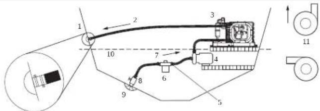
!eaGater sFstem
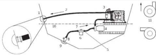
)eaGater outlet 7 Uphill inlet floG
2 h ulet floG 81 all valve
6 Air conditioner A! coop thru-hull inlet
9 EaCater pump) B V ater line
: e ose clamps) ] correct pump head strainer orientations
6! trainer
J. Install a seaGater scoop thru-hull inlet as close to the keel and as far Eelog the Gater line as possiEle. I ecure the scoop thru-hull inlet using a marine-grade sealant designed for underGater use.
2. Install a Bronze+ull-floG seacock on the seaGater scoop thru-hull inlet.
M. Install a seaGater strainer EeloG the level of the pump Gith access to the /iter.
4. Mount the pump aEove the strainer and at least one foot Eelog the Gaterline.
P. | connect the seacock and strainer Gith an uphill run of reinforced marine-grade hose.
Q. I connect the discharge from the pump uphill to the Eotom inlet of the air conditioners condenser coil Gith a P/S in reinforced marine-grade hose.
R. ] onnect the discharge from the condenser coil to the overBoard discharge thru-hull /tting Gith a P/S in, reinforced marine-grade hose.
S. Avoid loops high spots or the use of T0f elEoGs Gith the seaGater hose. Kach T0f elEoG is equivalent to 2.P b 10.RG m oil hose and a T0f elEoG on the pump outlet is equivalent to 20.0 b IC, J mOJ oil.
T. AouEle-clamp all hose connections using tGo stainless steel clamps reversing the clamps Where necessary.
[0.] onnect all metallic parts in contact Gith seaGater to the vessels Eonding sFstem.
7/9 Ma3ing eletrilal lonneltions

A NING-EleItrIaI s'013'a5ard
AlGaFs turn on the air conditioning poGer supplF Ereaker Eefore opening the electrical EoL. Yaiture to oEef this Garning could result in death or serious injurF.
Knessure the electrical CoL is located in an area that is protected from Gater.

NOTICE
Che air conditioner must Ee connected to the Eaats Eonding sFstem to prevent corrosion due to staF electrical current. All pumps metallic valves and fittings in the seaGater circuit that are isolated from the air conditioner EF 9a] or ruEEer hoses must Ee individually F Eonded to the Eaats Eonding sFstem.

NOTE Failure to properIf ground and Eond the sFstem Gill void the GarrantF.
All conditioning units have a terminal striplaEeled for proper connections inside the electric EoL. Che Giring diagram inside the electric EoL supersedes Al X] standards. Use the correct size circuit Ereaker to protect the sFstem as specified EF the air conditioning units data plate laEel. A minimum o2] 2 AV B Eaat caEle should Ee used to suppIF poGer to the air conditioner and the seaGater pump. Make all connections using ring or captive fork terminals.
h Eserve the JolloGing Ghen making electrical connections?
[Alternating current A] grounding must Ee connected to the ground terminal B RNA at the A] poGer input terminal Elock.
[ ] onnections EetGean the vessels A] sFstem grounding conductor and the vessels direct current VA] negative or Eonding sfstem should Ea made as part of the vessels Giring.V hen maintenance or replacing elisting equipment that has a chassis-mounted ground studl check the vessels Giring for these connections.
[BaCf and Cf air conditioners are designed to operate on A] or high voltage A]. Refer to the vessels Giring diagram for correct placement.
Ensure that the A| ground of the air conditioner is properF connected to the A] ground o the Eoat, V within the Eaot itself ensure that the A] ground Eus is connected to the A] ground Eus at elactF one place.
]heck and retighten as necessary all electrical connections prior to start up.
8 Disposal

CAUTION-Fire a5ard
This device contains flammaEle insulation EloiGing gas.
nlf have the device removed and disposed of EF a specialist.

Place the packaging material in the appropriate recFcling Gaste Eins: Cherever possEle. I onsult a local recFcling center or specialist dealer for details eOut hoG to dispose of the product in accordance Gith the applicaEle disposal regulations.
A Tel'nilal data
Read these instructions completely and then plan the connections that must be made to the air conditioner (including ducting) condensate drain line seaGater inlet and outlet hoses electrical poGer connections location of the control and seaGater pump placement to assure easF access for routing and future maintenance.
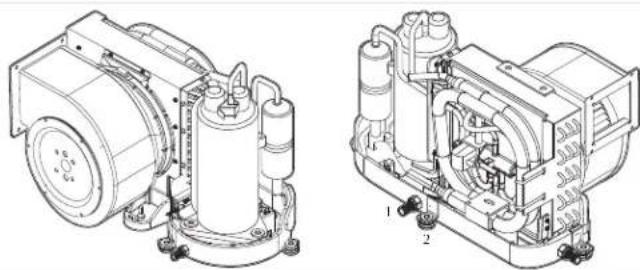
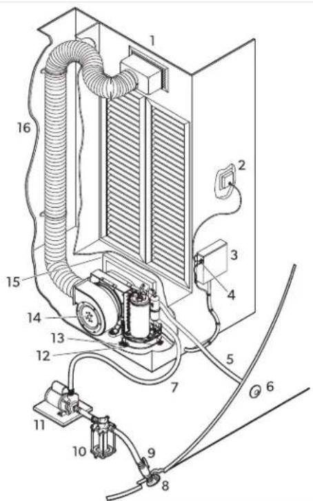
A/) Part lotations
Air] conditioning! [stem] component Identification
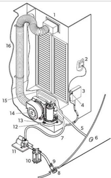
uppl air grille and transition Eol
A Ieacock shut-od valve
2 Aigital displaF
B!eaGater strainer
6KlelectricEol)9ump
9 h p tional remote air sensor caEle 2] ondensate drain hose EarE
: 1eaGater outlet hose)6 Mounting Eracket
6 h verFoard discharge)9 Air conditioner
7!eaGater inlet hose): Return air grille and filter
8!eaGater scoop thru-hull inlet)6 Insulated JeLiEle ducting
A/2 Speliliflations
Che refrigeration circuit contains a small quantitF of an environmentalf friendf Eut flammaEle refrigerant. It does not damage the ozone laFe and does not increase the greenhouse eect. AnF leaking refrigerant maF ignite.
This product contains fluorinated greenhouse gases.
The cooling unit is hermetically sealed.
Ta, le): Minim0m d01t and grille si5es per BTU lapaity
| 6/3 BTU 63 BTU 83 BTU | B3 BTU | |||
| Minim0m d01t diameter | M.00 in IRG.2 mm³ | 4.00 in BJ 0J.0 mm³ | P.00 in BJ 2R.0 mm³ | Q.00 in BJ P2.4 mm² |
| Minim0m d01t area | Q.S inj IMRT cmj0 | J2.0 inj HSJ.M cmj0 | J.T.G inj BJ 2G.P cmj0 | 2S.M inj BJ S2.0 cmj0 |
| Minim0m retOrn air grille | 4S.0 inj IMOT.R cmj0 | Q4.0 inj N4.2.T cmj0 | S0.0 inj WPJ.G.2 cmj0 | J00.0 inj WG4P.2 cmj0 |
| Minim0m s0pply air grille | J2.0 inj IRR.4 cmj0 | M2.0 inj N20.Q.P cmj0 | 4S.0 inj WOT.R cmj0 | Q0.0 inj NRSR.J cmj0 |
| )23 BTU)63 BTU)83 BTU | 27 3 BTU | |||
| Minim0m d01t diameter | Q.00 in BJ P2.4 mm³ | R.00 in BJ RR.S mm³ | R.00 in BJ RR.S mm³ | S.00 in N20M.2 mm³ |
| Minim0m d01t area | 25.M inj BJ S2.0 cmj0 | MS.P inj N24S.4 cmj0 | MS.P inj N24S.4 cmj0 | P0.M inj NR24.P cmj0 |
| Minim0m retOrn air grille | |M0.0 inj iSMS.S cmj0 | |Q0.0 inj iOW2.W cmj0 | 200.0 inj |2T0.4 cmj0 | 240.0 inj |P4S.P cmj0 |
| Minim0m s0pply air grille | R0.0 inj i4PJ.0 cmj0 | S0.0 inj NPJ.0.2 cmj0 | J00.0 inj iQ4P.2 cmj0 | |20.0 inj iRR4.2 cmj0 |
Ta, le 2: Operating water temperatOre and pressOre
| Minim0m operating water temperatore 40.0i¥14.44i] 0 | |
| Maxim0m operating water temperatore S0.0i ¥120.0Gi] 0 | |
| Minim0m operating water pressore | 4.2 psi 10.2T Earl 12T.00 k9al |
| Maxim0m operating water pressore | 0.00 psi 10.4| Earl 4| .4 k9al |
YolgoK9A use conditions.

NOTE: Che unit can operate outside these conditions Gith reduced capacitF.
B Legal
GVTX models only Co compf Gith IK] 0OPMdo not mount the product Githin T.S b m.00 m o a receiving antenna.
). arranty
Refer to the sections Eelog for information aEout GarrantF and GarrantF support in the U! + ] anada+ and all other regions.
United States and Canada
UIMICKA V ARRANCX AaAlu IA UK AC An MKCI] h M/KN-UI/CKRM1-ANA-] h NAICn N-] h NI UMKR/V ARRANCX.IY Xh Ue AaK u KI CH N I H R Ch n I CAIN A] h 9x h Y Ce JUMICKA V ARRANCX YRKK h ] e ARB-K] h NCA] Z
DOMETIC CORPORATION
MARINE CUSTOMER SUPPORT CENTER
2000 NORTH ANDREWS AVENUE
POMPANO BEACH, FLORIDA, USA 33069
1-800-542-2477
Asia-Palifi7APAC81oOntries
If the product does not Gork as it should please contact Four retailer or the manufacturer's Branch in Four countF see domeric.com/dealer.Che GarrantF applicaEle to Four product is J Fear!.
Yor repair and GarrantF processing! please include the JolloGing documents Glen Fou send in the device?
[ A copF of the receipt Gith purchasing date
A reason for the claim or description of the fault
Note that self-repair or nonprofessional repair can have safety consequences and might void the GarrantF.
Australia Only
h ur goods come Gith guarantees that cannot Ee eluded under the Australian I onsumer UaG. Xou are entitled to a replacement or refund for a major failure and or compensation for anF other reasonaElF booreseaEle loss or damage. Xou are also entitled to have the goods repaired or replaced if the goods fail to Ee of acceptaEle qualitF and the failure does not amount to a major failure.
New Cealand only
This GarrantF policF is suEject to the conditions and guarantees Ghich are mandatorF as implied EF the] onsumer Guarantees Act JTTMNm.
All ot'er regions
The statutorF GarrantF period applies. If the product is delectivel please contact the manufacturer's Branch in Four countrF (see dometic.com/dealer or Four retailer.
Yor repair and GarrantF processing! please include the JolloGing documents Glen Fou send in the device?
[ A copf of the receipt Gith purchasing date
[ A reason for the claim or description of the fault
Note that self-repair or nonprofessional repair can have saetF consequences and might void the GarantF.
De0ts1
[ American I oat and Xacht] ouncil AI X] 3
[AN!I/NY9AR0-NationalKlectrical]odeNK]
2/2 Si' er' eits' inweise


Adjustment screG
2 | loGer
KINB K! eR N' CK BKV rERJKI CUNB aKRYx B I AR UNCKR Ah MKCI] h M/ KN-LI/CKRM-ANA-1 h NAICIN N-1 h NJ UMKKR/V ARRANC.V KNNIK YRAB KN eAl KN AKR KINK h CKNuH K H 9k AKR KINK B] eR N' CKN BK V reRUKCUNB KRe AUCKN MS eCKNH V KNAKN IK I] e I CKAN
DOMETIC CORPORATION
MARINE CUSTOMER SUPPORT CENTER
2000 NORTH ANDREWS AVENUE
POMPANO BEACH, FLORIDA, USA 33
1-800-542-2477
LDnder im a0m Asien4Pa5ifi3 7APAC8
[ American I oat and Xacht] ouncil AI X] 3
[AN!I/NY9AR0-NationalKlectrical]odeNK]
2/2 Consignes de sL10ritL

DANGE - is 0e dlinTendie 0dNexplosion/ Cetails modNles Otilisent do rfrigLrant inflamma, le/

Adjustment screG
2 | loGer
[ American I oat and Xacht] ouncil AI X] 3
[AN!I/NY9AR0-NationalKlectrical]odeNK]
onectorde9a|0P in |2Rmmf L
OP in 2R mmM9C0
Adjustment screG
2 | LoGer
.1 olte os paralusos de ajuste do anel de montagem do soprador.
2. Rode o soprador at" a posicao pretendida.
M. Aperte os paraludos de ajuste.
6/2/2 Sopradores MCS, ECD e GT
A/! Lo1ali5ajoes das pej as
Identificacao dos componentes do ar condicionado

Brade de corneIncremento de ar e cail a de transicao
A alyula de corte
2 Monitor digital) B Ylto ra da agua do mar
6kuadroel"trico)omEa
9]aEdo sensor de ar remoto optional
Kspiga de mangueira da sida de agua de condensacao
: Mangueira de saida de agua do mar)6 | uporte de montagem
6 Aescarga de eLceso)9 Ar condicionado
7 Mangueira de entrada de agua do mar
B rade e iltro de ar de returno
8 Kntrada de recolha de agua do mar atray's do casco
A/2 Espelifiljoes
Todas as o0tras regioes
[ American I oat and Xacht] ouncil AI X] 3
[AN I/NY9A R0-National Kielectrical]ode NK]
2/2 Istr05ioni per la si10re55a

PE ICOLO- is! io di inlendio o esplosion/ Al10ni modelli 0til55ano refrigerante inflamma, ile/
6 Pre-installal5ione

AVVISO

Adjustment screG
2 | loGer
Raccordo in 9a]0P in 2-R mm e L OHP in 2R mm M9C
[ American I oat and Xacht] ouncil AIX
[AN!I/NY9AR0NationalKlectrical]odeNK]
2/2 Veilig' eidsaanwil5ingen

GEVAA - Brand- of explosivege2aar/ Sommige modellen ge, r0i3en, rand, aar 3o0demiddel/

Adjustment screG
2 | loGer
7/9 Ele3tris' e 2er, indingen ma3en

AA SCHU.ING-Ge2aar 2oor ele3tris1e s1'033en
[ American I oat and Xacht] ouncil AI X] 3
[AN!I/NY9AR0-NationalKlectrical]odeNK]
2/2 Si33er'eds' en2isninger

FA E-isi3o for, rand ell er e3splosion/ Nogle modeller an2ender, rd, art 3clemiddle/
Manglende overholdelse at falgende advarsler vil medare dodsald ell er alvorlige kvaestelser?
Ma kun repareres a uddannet servicepersonale.
Ma参加会议的股东和代理人。
org for at alle ndvendige ventilationsA Einger erri for Elokeringer.
Undg at punktere klermiddelslangerne.
!e Produktets tFpemaerkat for kolemiddeltFpe.

ADVA SEL- Brand- og4eller e3splosionsfare

Adjustment screG
2 | loGer
J. Løsn indstillingsskruen pa Elaeserens monteringsring.
2. Arej Elaeseren til den onskenede position.
M.!paend indstillingsskruen.
6/2/2 MCS-, ECD- og GT-, lb sere
M] -HK A- og BC-sFstemets Elaeserrotation

DA
)!creG
2 Uaske
6 | laser
[ Yilteret skal vare under pumpen.
A/) Delenes pla1ering
Identikation a klimaanlaggets komponenter
DA
#

) UitorsFningsgitter og overgangsEoks A perreventil pa sohane
2 Aigialt displaF) B e avvandsilter
6 KIFoks) Gunpe
9 'aEel til Jernluitensensor option) 2! langekrog pa kondensataillE
: UdlEsslange til havand)6 MonteringsEeslag
6 UdenEordsudgang)9 limaanlag
7 Indlo[sslangetihavand]:Returlutgitterog -ilter
8! coop-skrogindle til havvand) Isolerede leksel kanaler
A/2 Spe1ifi3ationer
[ American I oat and Xacht] ouncil AI X] 3
[AN!N/ny9A R0-National Kiectrical]ode INK]
2/2 SD3er'etsan2isiningar

FA A- is3 fHr, rand erer explosion/ Vissa modeller an2Dnder IDtantDndligt 3ylmedel/
h m man underlater att lqla lqjande varningar Elir qlden dcdsall ell er allvarlig personskada
Adjustment screG
2 | loGer
.ossa stllskruven pa flnktens monteringsring.
2. arid flinkten till qnskat Inge.
M. Ara at stnllskruven.
6/2/2 MCS-, ECD- o1' GT-fD3tar
[ American I oat and Xacht] ouncil AI X] 3
[AN!I/NY9A R0-National Klectrical]ode [NK]
2/2 Si33er'etsinstr03sVoner

FA E-Fare for, rann ell er e3sploslon/ En3elte modeller, r03er antennelig 3Vclemiddel/
ADVA SEL-Fare for ele3tris3 stct
ADVA SEL-Fare for ele3tris3 stct

Adjustment screG
2 | loGer
J. Løsne justeringsskruen på testeringen.
Gelder 30n for New Cealand
Aenne garantien underligger vilkarene og garantiEestemmelsene i JorErukergarantiloven] onsumer B guarantees Act ITTMNm.
Alle andre regioner
Lovmessig garantitid gjelder, o vis produktet er de'ekt? Ca kontakt med produsentens Whial se domestic.com/dealer' ell erhorhandler i dit land.
2/2 Tor2allis00s'Vect

VAA A-Palo-tai rDvD dys2ara/ eoissa3in malleissa 3DytetDDn syty2DD 3yImDainetta/

Adjustment screG
2 | loGer
[ American I oat and Xacht] ouncil Al X]
[ANI I/NY9A R0-National kElectrical]ode NK]
2/2.s3a5sW3i,e5pie15enstwa

[ American I oat and Xacht] ouncil AI X] 3
[ANI/NY9A R0-National Klectrical]ode [NK]
2/2 Be5pevnL po3yny

NEBCPER ENSTVO-Ne, e5pevenst2o pogiar0 ale, o 2w, 01'0/
Nie3torL modely poQt2alu' orxa2L 1'adia1e mLdi0m/
Nedodrzanie nasledujucich varovani Eude mal za naslodok smrl aleO vazne poranenie?
pravu moze vFkonávali Ea vFskolenfi servisnf personal.
Neinstalujte ani neskladujte na mieste s nepretrzite ungujucimi zdrojmi vznietenia.
Udrziavajte vsetkF pozadovan' vetracie otvor F eez prekaZok.
Neprepichujte hadickFs chladiacim m diom.
Cfp chladiaceho m' dia najdete na tFpovom stitku produktu.

VsST AHA-Ne, e5pevenst2o poqiar0 a4ale, o 2w, 01'0
Nedodrzanie nasledujucich varovani moze ma za nasledok sm aleO vazne poranenie?
Na zistovanie aleOv vfladavanie unikov chladiaceho m' dia nepouzivajte potencialne zdroje vznietenia. Nepouzivaje halogenidovfi horak ani infdetektori kortfi pouziva otvorenfi plamn.
Uistiţie sali Že detekčn" zariadenie je vchod" pre tFp chladiaceho m" dia použit" ho v pvrodukte. Inormácie o tFpe chladiaceho m" dnia najdete na Štikku produktu s udajmi.
Klektronick"detektorf netesnosti mozu EFpuozit"na detekciu uniku chladiaceho m'dai avsak ich citliovs moze EFn nedostocn pre hor'av chladiace m'dia a moze EFn potreNa rekaliEria. AliErujte detekcn" zariadenie na mieste Eez chladiaceho m'dia.

VsST AHA-Ne, e5pevenst2o oxid0 0' oxnatL'o
Nedodrzanie nasledujucich varovani moze ma za nasledok sm aleO vazne poranenie?
Neinstalujte ani neprevadzkujte autonomnu klimatizaciu v podpalEu i ani v stojovnili prapindve v Elizkosti spa'ovacieho motora. maEzepez' aEF Eolo vFer" miestochrane" pred priamFm pristupom do podpalEuia/aaleEo predvpiarmi zo strojovne.
Ikontrolujte ci je potruEie na odvod kondenzatu spravne nainstalovan" a utesnen". Neukoncujte potruEie na odvadzanie kondenzatu do vzdialenosti m stop tTj m od ak "hokofvek vfistupu vfukov" ho sFt" mu motora aleOe generatoraV sekci s motorom aleOe generatorom aleOe v podpaluPikai' ni je odtok spravne pripojenf ki utesen" mu Cerpadlu na odvadzanie kondenzatu aleOe opdavej vodF. Ak odtokov" potruEie nie je spravne nainstalovan" neEezpecn" vliparF sa nim mozu Siriil a kontaminoval oEFtn" priestorF.
NeinStalujte klimatizaciu na miesto!kde moze cirkulovaf ol id uholnatif palivov'vfiparAleOe in'skodliv'vfiparDoEFtnfich priestorov lode.

VsST AHA-Ne, e5pevenst2o 5Xsa' 0 ele3tri13wm prudom
Montáz smie vFkonávaI len kvalikovani elektrikar.

VsST AHA-Ne, e5pevenst2o 5Xsa'0 ele3tri13wm prudom, poqiaro a4ale, o 2w, 01'0
Nedodrzanie tfticho opatreni moze maf za nasledok smr aleEo vazne poranenic.
Coto zariadenie nie je urcn" na pouzivanie osoEami hvratane deti s oEmedzemfini zickfimlzmFSlovfimi aleO duSevnfimi schonosfi amleO nedostatkom skusenosti a znalost' pokial nie su pod primeranfm dohladom aleO ich osoAeh ktorae j zo zodpovedna za ich Eezpecnosd dokladne nepouci o pouzivania zariaidenia. Aohliadnite na toa EF sa deti nehrali so zariaidenim. -istenie a Eeznu udzeu nemsu vfKonavat deti Eez dozoru. Coto zariadenie nesmie Effd dostup" sirokej verejosti.
SK

VsST AHA-Ne, e5pevenst20 2w, 01'0
Nedodrzanie fichto opatren moze mal za nasledok smr aleO vazne poranenie.
'limatizaci neutristalujte na要比o kde sa nachadzaju Eenzinov" motorFl nadzei [aSe na 98B/98H regulatorF ventilF aleEo armaturF palivov"ho potruEia. Ak nie je uveden' inakonomne jegnotf nepshajufederalne poziadavkf na ochran pred vznietenim. Nedodrzanie toto varovania moze ma z nasledok smr aleEo vaze poranenie.
Kleektrick suciastki kton" mozu sposoEi elektrickfoEik aleOiskru sa mozu nahradi iA caslami SpecikovanfimviroEcom spotreEica. a fimena za in" dieIF moze maf na nasledok vznietenie chladiaceho m" dia v pripade unku.

VsST AHA-Ne, e5pevenst2o 5Xsa'0 ele3tri13wm prudom
Nedodrzanie tichto opatreni moze maI za nasledok smI aleO vazne poranenie
Uistite sa ze je klimatizacia ifinne uzemennai aEF sa minimalizovalo riziko zasahu elektrickim prudom. Dalsie inormacie najdete vPokFnoch na monta.
'ažda instalovaná klimatizácia vFzaduje vlastnǐ istic. Ak sa instaluje iEakeletalite klimatizácia-cerpadlo morskej vodF neVfzaduje vlastnī spinač. 'edjedno aleOviacer' klimatizačn' zariadenia použivaj rovnak' cERpadlo morskej vodF pripoja sa vodiče cERpadla na platn rel' cERpadla 9R9Hkortá je vFvavena vlastnīm ističom podl' parametrov cERpadla lmal.20A. 3ozrìte si sch'mu zapojenizia z Rozsahu dodávKF 9R9. 9ri elektrickfich pripojenič vi podpaluEi a/aleEo pod urovouh hladin F vodF je potreEn' použil teplozmrsfovacie kElov' spoje.
Jokalne zapojenie musi zodpoveda! elektrickfm predispom A] Napajanie zariadenia musi EFV rozahu prevadzkov' ho napria uveden"ho na tFovom stiku. Na ochranu elektrick"ho okruhu vetvenia sa musia nainstalovaf sprvnve dimenzovan" poistkF aleOiste eA] R. Malimnu ve'kospiostk/F/istiMa minimalnu kapacitu oEvodu M] Au najdete na tFovom stiku.

POCO
Coto zariadenie oEsahuje fluorovan' sklenikov' pIFnF v hermetickF uzavretom s'stme. Mnozsto chladiaceho m'dia uveden v Jednotkach hmotosti a BV 9 najdete na Fpovom stuk kondenzačnej Jednotk.F. Gridan' chladiace m'dium je potreEn' uiesi na stuku zariadenia.

POCO -
Nepouzivaje medenu hadičku na tlaceniet fahaniel zdvihanie aleOprenáanie produktu.
6 Ciexo2L s30piny

Mechanicku a elektricku instalaciu a nastavenie zariadenia musi vFkonai kvalikovani techniki ktori prekazal zrucnosti a znalosti tkajice sa konstrukcie a prevadzfk namorn ho vFEavenia a instalaciia ktori je oEoznameni s platinimi predpismi krajinv ktroje sa zariadenie Eude instalovaf aaleo pouzivai ktori aesolvola Eezpecnostn" skolenie zameran" na identikcu konkr" tnfch neEezpecenstiev a ich predchodzaniu.
9 Po0qT2anie 2{sulade sOrvenTm
Cento návod je urécní na instalaciu autonönnFch klimatizćnich sFst" mov AJ UH AUH ACB+K] A-B CH B CF +B CF -UH B A CF a CF dalej len klimatizácia. "límatiszá je určné na použitie na lodiach a jachutch. Cato klimatizácy je vchodn iEa na urcen" použitie a použitie y súlade s'tfmo návodom.
Cento vfoEok je vhodnf iE ana uren" pouzitie a pouzitie v sulade s fimto navodom.
Cento naved o'Saehu integromaci' ktor' su nevFnutn" pre spravnu instalaciu a/aleEo oEsluhu vfoEku. J HEna instalacia a/aileO nespravna oEsluha Ci udzEa Eude mail na nasledok esnpokojfvi vilk on a mozi poruchu.
a firoEca nenesie ziadnu zodpovednosi za ak'kol'vek poranenia ci skodFa viroEku sposoEen?
[nespravnou instalaciou aleo pripojenim vratane nadmem"ho napntia
[ nespravnou udriEou aleEo pouzitim infich ako originalnFch nahradnich dielov poskFtnufich viroEcoml
zmenami produktu Eez vislovn * ho povolenia vfoEcul
| pouzitim na in" ucelF nez na ucelF opisan" v navode.
!polocnosi Aomatic si vFhradzije pravo na zmenu vzhladu a technickfich parametrov viroEku.
: Vys2etlenie sym, olo2 na(5ariaden

9ozory Riziko poziaru/hor'ay"material

9ozorg Material s nizkou richiosl horeia. orfav' chaliadne m'dium.
[American] oat and Xacht [ouncil AI X] 3
[ANI/NY9AR0-National Kiectrical]ode(NK)
2/2 Be5pevmostn1 po3yny

NEBECPERi-Ne,e5pevt poqXrO ne,02w,01'0/Ne3terL modely 2y0q[2aI'orla2L1'ladi2o/
Nedodrzeni t' chto vfistrah Eude miz na nasledek smr neEv zran" n3 > h pravSm provad't pouze vfskolenisi servisni pracovnik.

Adjustment screG
2 | loGer
-
Uvoll"te seizovaci srouE na upevnovacim krouzku ventilatoru.
-
h tocte ventilator do pozadovan* polohF.
M. Ulahn"te se-izoyaci srouE.
6/2/2 VentilXtory MCS, ECD aGT
h taceni ventilatoru sft"muM]IHK]AaBC

)!creG
2 Štitek
6 a entilator
J.h deEerte sedm grouE, na desce.
2. h tocte ventilator do pozadovan'polohF.
M. majist"te ventilator na mist" pomoci samoeznich srouE, hnejsou socasti dodaVkFJ.
6/2/6 VentilXtor DCU
h tacei ventilatoru sFst"mu A] U

1 creGs on LioGer ring
2!creGs on drain pan or Bracket
J. h deEerte srouEf z krouzku ventilatoru.
2. h deEerte SrouEF pivevnjici ventilator k odtokov" van neE o konzole.
M. h tocte ventilator do pozadovan" polohF.
4. majist" te ventilator na mistsomoci samoeznifch srouE, njejsou socasti dodavkF).
P. Ucp "te vsechnF nepouzivan" otvorF aEFste zaEranili ztratam vduchu.
6/6 VloqenT 25d01' o2w1' filtru
azduchov" WlrF odstranuij ccastice ze vzduchu v kaEIn" audruji cistou civku viparniku. Gro kazdou klimatizaci umist" tejen vduchovfi WlrH a to Eud' na klimatizacnneDo do mizkf zp"tn ho vzduchu.
6/9 UmIsten mIq3 a(p) odo2w1 s3fne3
9i umislovani mizek a pechodovfich skin"k Eerte vuvahu nasledujici skutecnosti
[Mizku pivad"ho vzduchunainstalujte co nejvise na misto odkud Eude zajist na rovnoma distriEuce vzduchu v cel"kaEin".Mizov'zaluzie nasim'ruje nahoru.
[Mizku vratn" ho zvduchu instalujte co nejnize a co nejEiige ke klimatizaci aEF EFlo zajist" no proud" ni zvduchukvfipamiku.
[ifistup pivad'nho vzduchu nesmi'movat k mioce vratn'ho vzduchua opaen'mpapd EF dochazelo kopakovan mu zapinani aVF pinani sFst'muvkrktlich intervalech.
[maizkou pivad]ho vzduchoponechte dostatecnf volnf prostor propechodovou skinku apipojku potruE, aiz | pecikace na strance 2M
7Instala1e

Vs ST AHA-Ne, e5peV10smrIenIe3tri13wm proOdem Instalaci sm"ji provad"t pouze kvalikovani elektrkasi.
7/InstalaemontXqnT3on5ol aod2od0 3onden5XtO

POCO
AEFste zaEranili prasknuti odtkov " vanFl nepouzivejte k omotani hadicov" ho hrotu vice nez dv" vrstvF instalat' rsk' paskf a hadicov fi hrot piliis neutahujte.
Cpick'umist'ni montaiznich konzol a otdok, kondenzatau
e rot hadice na otdok kondenzatu
2 Montáñí konzola
Instalace otdoku kondenzatu pro sFst ^f BCF+BaCf+ACBaC

eoseEar9Arain pan
2 mavitovf otvor otdoku: h dtokova hadice
6aFrazeni zaslepkF
CS
Instalace otdoku kondenzatu pro vsechnF ostani klimatizaChi jednotf
) Locking nut 9 !olid Gasher
2 h dtokova vana
9a armatura 0P in y2R mmol L OHP in y2R mmol M9Cl
6 Godlozka kapalinov ho t" sn" ni
JCednotkFBcHBaCfHACBacFz
a ezm"te malfi konec hadicov' ho hrotu aVFzote zaslepku z VFpoust"ciho ovtor sm" ujiicoh k zadiud leje toejimr fchlim udereem gumov" palickF. aFrazenou zaslepku zlikvidujte.
Eh moteje zavitovf konec hadicov"ho hrotu instalat"rskou paskou.
c NaśrouEujte hadicovf hrot do zavitov' ho otvoru odtoku a pevn" jej utihn'te.
- Gro vsechnFostatni klimatizace?
a e adicovfi hrot provl"kn"te pevnou podlozkou a podlozkou kapalinov"ho t"sn" n azasunite jej do otdokov"ho otvoru.
Eo majist"te pojistnou matici.
M. Gisepv"te odtokovou hadici k hadicov"mu hrotu pomocihicov svorKF z nerezov" oceli.
- h dtokovou hadici ved'te sm rem dol, k Eezpecn" mu a vhdn'mu sE'm' mu misti. Instalace montažni konzolf pro jednotk BF Cf + BaCfH ACB aCf
Montažni Čepinénsoučasti dodaVkF
2 Godlozka chranié tje soucasti dodavkF
6 Montáñí konzola je soucasti dódvkF
Refrigerant Safety Group A2L
! igurnosna grupa rashladnog sredstva A2U

Grocitajte upute za uporaEu.

Grocitajte servisni prirucnik.

POCO
h vaj uredjad surdi z fluorirane staklenicke plinove u hermeticki zatvorenoj opreim. 'olicina rashladnog sredstva prikazana je kao masa 1 BV 9 na naljepnici tipske ploice kondenzacijske jedinice. Aodano rashladno sredstvo potreEno je uiljeziti na naljepnicu jedinice.

POCO -
I akrene cijevi nemojte koristiti za guranje povlacenjeh podizanje ili nosenje proizvoda.
6CilVne s30pine

Mehaničku i elektrčnu montažu te postavljanje uredaja smije provoditi samo kvaličirani tehnicić koji je pokazao vijěstinu i znanje verzano za konstrukuju i rad pomorske opreme i izvodenje instalacija koji doEro poznaje važece propíse države u kojoš se oprema treEa instalirati i/ili koristiti i koji je prosao oEuku o sugurnosti koja mu omogucava de prepozna i izE jegne opasnosti koje se pri tome javljaju.
9 NamVena
h vaj e priručnik namijenjen za montazu samostalnih sustava klima-uredaja A] UH AJUH ACB+K] A-B CH B Cf +B Cf -UH BaCf i Cf [dalje u tekstu klima-uredaj]. lima-uredaj namijenjen je upotreEi na Erodovima J hajtaje. h vaj klima-uredaj prkladan sanso za predvidenu namjenu i primjenu u skladu s ovm uputama.

Adjustment screG
2 | loGer
] Yan montaj halkas' pzerindeki afar vidasin' gevsetin.
2. Yan'istenen konuma dqndprpn.
M. AFar vidas/n's/kn.
6/2/2 MCS, ECD 2e GT fanlar
M]HK]AveBCsstemtandqnpso

) Screw
2 Plaka
6 Fan
Screws on blower ring
2 Screws on drain pan or bracket
UgA I-gangin 2eya patlama ris3i
h ur goods come Gith guarantees that cannot Ee eIuded under the Australian I onsumer UaG. You are entitled to a replacement or refund for a major failure and or compensation for anF other reasonaElf looreseaEle loss or damage. You are also entitled to have the goods repaired or replaced if the goods fail to Ee of acceptaEle qualitF and the failure does not amount to a major failure.
galm51a geni Celanda
I u garanti politikas] onsumer Buarantees Act TTMNncPketici B arantileri Xasas0 taraland Eelirtildigi pzere zorunlu olan kosullara ve garantilere taEidir.
TEmdiger, Hlgeler
Xasal garanti sponesi gecerlidir. x rpnde hasar varsa preticinin plkenizdeki suCesi Ekz. dometic.com/dealer veFa satcincla iletisime gegin.
[ American I oat and Xacht] ouncil AI X] 3
[AN!NY9A R0-National Kiectrical]odeNK]
2/2 Vamostni napot3i

NEVA NOST-Ne2arnost pogara ali e3splo5Ve/V ne3ateri mod0li Ve 2netli2o'ladilno sredst2o/

Adjustment screG
2 | loGer
- I laEi suruEul de reglare de pe inelul de montare al suflantei.
- Rotili suflanta la pozija dorita.
M! trangej suruEul de reglare.
6/2/2 Soflantele systemelor MCS, ECD i GT
Rotirea suflantelor systemelor M]IHK]A sICBC
RO
#

)!creG
29laca
6!uIantà
J.1 coate)i celesapte suruEuri de pe placă.
2.Roti)isuflanta la pozi)ia dorita.
M. YiLai) suflanta pe pozijie utilizand suruEuri autoletante nu sunturnizate1.
6/2/6 S0flanta DCU
Rotirea suflantei systemuli A] U
#

1 creGs on EIoGer ring
2!creGs on drain pan or Eracket
J.1coate)i suruEurile de pe inelul suflantei.
2.1 coate)i suruEurile care Wleaza sufflanta petava de scurgere sau consola.
N. Roti) suflanta la pozi)ia dorita.
4. Yila'i suflanta pe pozijie utilisizand suruEuri autoWetante nu sunturnizate
P. Astupa'i ori'ciile neutilize pentru a preveni pierderile de aer.
6/6 Amplasarea filtrelor de aer
PEPyPEKDEHNE-OnaCHOCTOBBFIEPOeHOCKn
He, n54B5H-7n5, neHn2-e n. e8n13678e 5n7ne 7, 6b. -2n2 e, 274H7 H5.5H3B5He
He 67H-2.5H-e 2 He. 567-e-e, b, 567, -73-een 0n265-20 a.. 1065 2n2 B 65m2HN7-7 7-denee 2e 2n 8n247,-a/7dB2r5-cn, bB.. cHH/7. cHe. Ybe.e,e, eue 246.5m7-763,-7e 45neu5-5n-72.e0eH7,-bN7 24n5. cH23-5 H5-1065 2/2n2 65m2HN7-7 7-denee 2e.
I7B.e-e5n2n2H3-545 24-7yBHeH507HHeH45-5e n.5B2nH7 67H2.5H5245neq5-5H.He 45Bb.1uB5Ee2n23-54524-7yB5He H507HHeH45-B.5602-eH5OITJ m b3-7-07i-72e5e24x7n5 24n/,05eHN5-5,2,e65H5D82r5e2n2TReE.5-7.1B7denee2e TmB.85E7An2r5-en2n2rehe.5-7.12n2B..1o6517,HH50724-7uBHe-7 e B.45H7n.5B2n7b645neue-5n76n54507HHeH45-2n2n76n5 4524-7uB5He.A07n2H3-54524-7uBHeHoC n.5B2nH767H-2.5H5F 7n5,H2-e24n5.EH2367r-5e,ep.2B285-Hs7.e7He32d456b,3 82n2Eh2-e176eFeh23.
He 67H-2.5iH265-205 H537H0Ee-7678e1512.0/n2.5 BbrHe.7dH 70,2n7B2H25.22n2D,/r2B.eH224n5.EH23 B 82n2E2H-2e176eEeh23H57n05-5.

PEYI PEKDEHNE-OnaCHOCToEJIeKTPNueckn ydap
M7H-58b-678e 5,e24BB.1B5,5677-0B5n2Φ212.5H e9e0-7-exH20.

PEPyPEKDEHNE-OnaCHOCTOTOKOByap,noKapn4HH
EKCNIIO3N
He.n54B5HE-7H5-e42n.ea154H26e.02678eA57Bede7,6b.-2n2 e.274H7HS.5H3B5HE.
:O6aCHeHHe Ha cIMB0JIHTe Bbpxy ypeJa

Pi.8n/n.e8n2e0n5,n7,-7-n785./45n5n262 65-e.25n2

Pi. e/π.e8eH2eM5-e.25π, H2.05, 07.7,-H5r7.ehe.35-15n26 x15a2neH SreH
Γ./m5456e47m5,H7-H5x152n2H23SreH-A20

II.7y-e-e.07B7n-b7-745e0,nn75-5123

II.7ue-e-e.b07B7a-b7-74576n/8b5He.

BHIMAHNE
742/,8n,b1b.85Φ/7.2.5H215.H207H2r547BneXe.6e-2ue,02 45-B7.eH7.b7.b8EHe.B28-e-2π7B23e-20e-45π.7d/0-5 H5 07HnE45127H235.rer5-4507a2ne-H-7x5a2neH5reH+H7,7ueH705-7 -ern72BV9.0765Bn3-x5a2neH5reH-..36B5456bme7-6en345m.m.x/ e-20e-5n5/,cd5.

BHIMAHNE
He 24n7n45n-6e9n5-5. b65+45 n56/-5-e n5-n7Bn2r5-e 2n2 n.eH5,3-e n.7n/0-5.
6IeJIeBa7n8 rpyna7n8

Mex5H2uH5-52e0-2ue,05-52H,-5n51232H5,-7H05H5/-7H,-B7-7 36B5d5,e24Bb.1185-7-CB5n2Φ212.5H-exx20,/6en2324H5n23 H,BB.45H2,24r.58aSHe-72e0,ππ75-5123-5H567,-07-7767./dB5ne 2 2H,-5n5122H207H-745n74H5-n.2n78262-e.54n7.e62H5b.85B5 H073-7767./Jn5n7-36b5d56nE67n-2.5n72/2n224n7n4n7+2 e n.E62H5n76/yen2e n7647n.H7,+45d52eH-2Φ212.5246er He ,Bb.45H2-e,-7B57n5,H7,-2.
9 N3noJ3BaHe no nppeHa3HaueHne
H5,-7347-7, b077d,-b7e n. eBn54h59e74 65 67H-2.5he H5 58-7H7620n265-2uH2 2,-e62m5.245n27-n7/n265-20C[A] UAUJACBHK[ABCHCBHFCHFc-f9-BaCF 2Cf.KJ265-20b-e n. eBn54h59e45 24n7n4BHe5H7n0223x-2.T7420n265-2e n7n7d3E, 56745n. eBn2en5-1e1n2n78en2e,brrn5.H7H5,-734E-2n-,/0122.
T742n.7a/0- en7ax734,56745n.ea2aeH5-51en2n.278e2e,bn5,h7 H5,-73E2-e 2n.-/0122.
T7B. b07B7d, -77 p e7, -5B32h7. 65123HHe76x726545n. 5B2nH5-52H,-5n5123 2/2n2 e0, n75-5123 H5n. 7d/0-5. 17w72H, -5n2. 5He 2/2n2 HeH. 5B2nH5/n7. e65 2n7u. 8COS Ae 7neu5-7He45a7n72-eun5. 567-52eenn/-5n7n7n.e2.
6jOIOTOBka3aMOHTaK

BHIMAHHE
567,-73eH2-e-SB24507HHe4545ACBHcHbCf2Cf,5767./B5H2n26.7247n5-7.2H7-2n5n7-7n5-Sn2-e.Te42247n5-7.2.5n.7e0-2.Sn2-505ueA5n7-2,05-2n6.5122eHn.2q2He27.-.567-e4230n265-20dHEcn.EH5-3Bv/67H-2.5H5-5n7BxH,-II.2n.e6-BsHe H0n265n767H-58Hn7BxH7.-.36B5d,eBn265B+ -h05-7247n5-7.2-e67r5-d5e7Bed3

BHIMAHNE-
Kn265-36854e67H2.5HS2,05Hn7,052.5BH5n7BxH7,H 05-7H5n.26e.BnH7-H5n05pHn7A,ep5n5-5H507u052n2 0510-076n5n2Hn7A/6n76n763.-7
Yne.e-e,elue056en2-e n365n5-7n78en2n524n7n5n9 07.7423n.n.0e76e.H7n3n3r5neH26.5122F7..2.67be2n2 A./r2ne6n5r7n.23-n2n4dien-n23n5707nn5-5. e51n0nou2-en17 B4dch.-B37-5.eene2n2n7-73HH2B26.51227-24-7HH212405-7 076n.e.7.2n2BEH-2n5-7.2.
Ye.e-eHne. eHn. eH5H- b67n. 7B72-e 2Φ2-2hr2-e, 5 4542-eH2170707-7b64678H7-7He6n7n. 23H7-7b64eH-b2e H 707H5-5. eH507-H5n. 26e.H5- nH5ne H6. 7-23-27-7602n2 n62.5ne 2456. 4H5ne H5n7n5 H76nOe2-EHH2-e. -62
T.36B545eB465-n.eqm54H26e.02H45n5,e246erH5-n.e076e.H2 n26.51222n2n/n,5122n5x5n52n23-67n.787n
6/OnpeJeIeHaMaCToToHaMOHTaK
J.P54n778eH2e H5BaCf 2Cf n7-7H7meH2e H5Bb4nH23n7-70
)00in8Q2cm
9 400 in 10 cm
2T7n7766em20:Peue-054576.5-enm4n/x
6II er.5d56Bb4JmeH7-70
P54n778eH2e H5B,2u02d,/r20n265-2uH2/,.7n,-B5n77-H7uH2e H5 B4/HH23n7-70

400in 00Gcm
9 W00 in R/G2 cm
2 Peme-05 45 76.5 en m4y/x: n. er. 5n5
6Bb4menn7-70
2.146.e-e63-7,7-5-1m7m4/menn7-70.Puee-05 45 76.5-en m4/x-.36n5 n526562n26/n.7,ne-7-4100in||0Qcm14512.0/n5123n5m4/x5n.egn3-6e4n2050n7.nen3-n2e.
M.A070n265-20e.54n7n78enne.nen20/n3.n7n5.eue-05-54576.5-enm4x/n17n.85n-e 62n265en n.7,be-7-MH0 in RIO2 cm/4512.0/n5123n5m4x/x57-5H5-5H5BX7n45BB4x.
4.CaMo3a GVTXnTX:O,2r/.e62H265nH57-0.2-5nn7E7-NH00 in RgO2 cm H5d2n7d.5d25-7.5.
6/2 3abpbTaHe Ha BeHTHaToppa
T742.54e763,H3B505d545BB.-2-eBEN-2n5-7.S45B,e02-2n/-.7H,-7H,-B7.A07 eHe76x7d267+45BB.-eBEN-2n5-7.5Bn7,705-5+073-7n74B7n3B5H5n-d2.e0-H7 24Xb.L3He H5Bb4J/WH23n7-70n.e4Bb4J/x7B72e.
6/2) BeHTnlaTOpHa GTX, GVTX, DTG n TX
Bb. -eHE H5 BEH-2n5-7. 5 H5, 2-e65-5 BcH BaCfH ACB 2 Cf
Adjustment screG
2 | loGer
1. P54x156e-e er/π2. 5A23 B2H- H5 π. b, -eh5 45 67H-2. 5He H5 BeH-2π5-7. 5. 2. 35Bb. -e-BeH-2π5-7. 5 B 8en5H-7-π778en2e.
M.35-erhe-e er/12.5E23B2H.
6/2/2 BeHTnIaTOpHa MCS, ECD n GT
Bb. -ehe H5 BEH-2π5-7. 5 H5, 2,-e62-e Knviro] ooH K] A 2 BC
)!creG
2T56en5
6 BeH-2a5-7.
J.O-,5He-e,ege6-eB2H-5H5n74S-5.
2.35m.-e-EBH-2n5-7.5B8en5H-7n7n78EH2e.
M.350.eeneBEN-2π5-7.5H563,-7H05-724π7π4B5-e,567H5.e4H2B2H-7BE1HE,5 n. eH7,-5nH20
6/2/6 BeHTHJatop Ha DCU
Bb.-eH5BEH-2n5-7.5H5,2,-e65-5A]U

0
1 creGs on EIoGer ring
2!creGs on drain pan or Eracket
J.O.5He eB2H-7Be e7-n.b. eH5 H5 BEH-2n5-7.5
2.0.-5HC-B2H-7BC-C-072-7450.cHB5-BCH-2n5-7,50b6d,ch58H23,bd2n2 0765-5.
N.35Bb.-e e Bn-2n5-7.SB8en5H7-7n7n78EH2e.
4.350.eene-ene-2n5-7.5n563,-7n05-724n7n4n5-e,567n5.e4n2B2n-7ne1he,5 n.e7,-5eH20
P.35n/ue-eB,2402 He24n7n485n2 7-B7.245A5n.e7-8.5-2e45r/65-5H5Bb4x/x
6/6octabHHe Hb3dyHHTe HnItpn
Bb4π/HH2-eΦ2π. 27,-5H3B5-Bb4π/HH2-e q5, -2127-Bb4π/x5 B0562H5-52
π7πB.85-6762H5-5H524π.2-en3q2,-5.II7,-5Be eπ7e2H BB4π/HH eΦ2π-B. H5
0π265-205 2πB. eH e-05-545 76.5-EH BB4π/x45 B, e02 0π265-20.
6/9 octabane Ha peWetKHTe H npexoDHTe Kyttn
π/62,ne-e45,neH7-7π.2n7,-5B3He-7H5.eue-02-e2π.ex7H2-e0/-221
[ M7-2. 5H e, EHE-05-545 n. 2-7eH B4n/x B4678H7 H5B2, 707 H5 63, -7H07e-7 7, 2E/3B5 5H6e. H7. 54n. eDeneH2e H5 B4n/x5 B0562H5-5. H5, 7ne-85n/42-e H5. eHE-05-5 H5r7.e.
[ M7H 2.5i e.eue 0554576.5e H BbA/x Bb4678H7 H5H-2,0726n247d7 0n265-205145A57,2r/.2-e m4/ueen n7-700624n5.2-en3.
[HeH5,7uB5n-e24n/05-eHn237-B7.H5n7A5B5n23Bb4x0b6.eHn-05-H 76.5-n23m4n/x1-n05-7-7B5Ae7nene70b7,bed2nne2eH5,2,-e65-5.
[O,2r/.e.7,-5-bn7,B767A7n.7,-5n,-B745a.eue-05-545n.2-7yeh B4n/x 45n.ex7u15-50/-232.B.405-5,B4u/x7B7a2-e.B28-etne12p205122u5,-5h215 JRP
7 INHCTaJInpaHe

iPEyj PEKDEHNE-Onachocr ot(eneKTpuecknyap
M7H-58b-678e45,e24m.1m5,5677-0n5n2φ212.51ene0-7-exn20.
7/ MoHTnpaHe Ha MOHTaKHNTE CkO6n H npEpaKa 3a KOHJeH3AT

BHIMAHNE-
35d5n.87-7-B.5-2-eH5n/0B5He H5d. eH58n23, b4n He 24n7n4B5n-e n7Beue
7-AB5,73B7A7n.7B7AH5neH-545/B2B5He H5E/1e.54565.0/452 He
45-35n-e n.e0SneH7A/1e.54565.0/45.
T2n2H7 n7, -5B3He H5 67H-58H2,0762d. eH582-e4507HcH45-5
)Ⅲ/1e.4565.0/454524-7n5ne 1307n
2M7H-58H5,0765
M7H-58 H5π. eH58 45 07HneH45-45 BCF+BaCf+ACB 2Cf
eoseEar9Arain pan
BG
2.0en58en7-n7. e65: 0en58en65.0/4
6 Tm5452462a5he
M7H-58 H5D. eH58 45 07HdH45-45 B,2q027,-5H5n20n265-212
1) Locking nut 9 !olid Gasher
2 en58en,
9a]Φ2-2HRΦP in||2Rmm|LΦP in 12RmmM9C
6Ynn-12-em5mS6545-em7-2
J.35BCf+BaCf+ACB2Cf67n/2
aH4n7n45u-e 65n023 0.5n n5A/1e.54S 65.0/45A52462e-e-5n57
A. eH58H237-B7.H50b.65-5H05-7 H5He, e e e2H 6b.4/da5. r/6eH q/0.
H4xm. ne-e 2462-5-5-5n5.
E06b2H-e 0.53 H5.e465-5 H5/1e.54565.0/45,777n7h5neH-5
c35B2n-eA/e/le.54565.0/95Bd.eH58n237-B7.,e465245-erHe-e4.5B7.
2.35B,2q027,-5H5n20n265-212
a11.e05.5H-eA/1e.5H65.0/u5n.e4-Bb.5u5u652/nBnH2-ennu6545
-eH7,-223B05.5n-eBn.EH58H237-B7..
E350.ene e,20,2.5E5rH05
M.350.cne-e.d.98H2365.0/Qb6A/e/le.54565.0/q5,b,07657-He.88d5e65
765H5
4.H5,7e e n. EH58H23 65.0/ue H5d7π/0b6 6e47n5,H7 2 n7dx7a3E7 63,-745 b62.5he.
M7H-58H567H-58H5,07654Bc+BaCf+ACB2Cf67A/π2

)M7H-58eH67n-heen.ey7,-5B
2 III5n65, m2.705 ne. 2pe. 23 n.e
A7-5BHeH5
6 M7H-58H5,0765 in. e7-5BcH5
M7H-58H67H-58H5,076545B,2q027,-5H5n20n265-212
)0e158en
2M7H58HS076S
6M7H-58EH67n-HHe en. e7,-5neH
P.M7H-2.5H eπ7 eH5 67H-58H5,0765- B,305,-5H5 H5 D. EH58H23,BH5-5BH2 54.-73H23.
M7H-2.5He H5 247π5123-57- neH7π5-45 BaCf 2Cf 67π/2

)47π51237-neH7nn5,-
2OB7.H5450,eB5A5-5m5H05
- en58en,
Q.35 BaCf 2 Cf 67A/n21
aO-,5ne-eΦ7n27-7+π70.2B5E7,56745nENB5A5-5,eπ7n7805H5 247π5123-5-ηn7πn5,-
E1P54n7n78c-e247n5123-57-nch7n5,-505+uea5n70.2eH5nBnH7-7-B.5H5 450.eB5A5-E5-5n5H5o5-05-7en05B5-5.-5H5e76b.H5-5C6d.EH58H23,bd
H5-2,He-e 707π77-B.5 H5450,enB545-5π5H05+45d545en2-e 247π5123-5 7- nEH7π5,-6b6, eH58n2,b
7/2 MoHTnpaHHe Ha Bb3dYxOBQDHTe

PEyj PEXKJEHNE-Otacnoctor nojk npn Eektno3n
07m1n2eH2/,-7H-B5-072-767r5-d56b5-24-7H212H545n55hEHE,67H-2.5-B-67H.7B7-2-e.54-n2H2-7,n765r5-eH2-e 7H-B5-26.7E24524n7A5H3,07HC.eH23./ed.
3567n2e124n7n4n5/245n5n262xn5n2n25re-1072-7,5,m.45n2 e4B4n/x7n7nH5,2-e65,eHN72n2n7Beue7n6e4En23n7n5b5n23 2n.BA5n23-4nH-x-36n5n5,5n2.e0-n7H5,7en206n76e4En2e-7. O-0.2-2e n.7,-5H,-85-07-7n5n.26e.705neH2-5B5H2-He.-36n5n5 ,e 24n7n4B5-05-7Bb4n/X7Bn4B5BbE5HEhBb4x.
He n.705.B5H-e B4A/x7B7a2-e n.e4 65u2HH7-7-aeHHe2e 2n2d/r7 63,-7+0bJe-7 67r5-a5 6b5-24n78eH2 H5 7n5,H2 24n5,eH23 2n2 2r7.e1n2547Be.
15485e,7nH2e,b,-73H23-07r5-767H-2.5ebb4x7B7a2-e
[Bb4/7n7n2-e-36n5n56n5-n7x7n3E77.546e.en245Bme-7n.2n78en2e.
[705.5n-8m4/77n2-eBm4678n7n5n-1.5n21m50227m5n5-2105-7,neae-n7 62H26/66.73n5T0145n72n.26021072-767r5-5n565n3-B4nnn23n7-70
[350.ene-e4d.5B7Bb4d/x7B7d5+45π.d7-B.5-2-eπ.7B2.B5He-76/.
[He7n/05n-e,nnE,OB5He2n. crBb5He5B4n/x7B7n2c.
[O-e8e-e 24n2HH2-e b82H2H5 Bb4x7B7z2-e,ne67H-585.
H47n2.5n-m4x7n7n2-e07r5-7,e1562.5-n47n2,n2,705-e6ne.5-/S.
A07,e24n7n45nex7nH50/-23H76E5-5nn7EHSb4n/X7B7p2e45n7n5B5HE5
m4n7x+24n245E27-0/-23-5-36n5n6bdeH5n6-E5n07.5nH5H576E5-5nn7EHS
m4n7x7n2e45n7n5B5NEBn245E280/-23-5.B28-e n12f025122H5,-5n215
JRP
B. b402 45 Bb4Д/х7В7Д2
14751237-26.7,-8079B- emeh mflar B4x774505H5n2
2M7n-58enn. -eir: T20,7
6II.ex7/1n50/23
1.Πb4He-eB-b-eun23mFlarBb4x7B74505H5n2707n767H-58H23n.b,-eHob6 n.ex7n5-50/-23.
2.35b2H-e-2 2π2e-2.2B2H-57-he.B85e65,-765Hπ.e4mFlar b4A/x7B7π4505n2B67H-58H23π.b-eH5-745xa5He-cde2π-2.28212,m5B2-c H5B2H-7Be-e.
MIIb4He-e 2475123-57-Φ26.7,-B0π7707πBb-euH23mFlar BB4x7B745 05H5n2O6πex7H5-50/-23.350.eene,-20.7.
7/6 HcTaIpaH He cHCTeMaTa 3a MOpcka BOda

BIHIMAIINE
He, n54B5He-7 h5-542 n. 71e/. 5 Ae 5H/π2. 5 r5. 5H123-5.
1548n-e,neH2-e,b76.58e23 n.224r.58d5He-7 H5,2,-e65-545 67.05 B7d5
[He05-3685x5e n7n76n5-5.
[M5.0/42-e-36B5d56b5d87H745xB5H52.
[M5.0/q2-eHe-36B5d5265-π. erb5H23rπ. 2602 2π2 B2,702 6e,-5r0b1e-7678e d5 e45nB.82 BB4J/x.
[1176π5-21e05-5.36B5d5,5π7B7π2H23-5.
[Bx7n-n.e407.n/51,pe.24n23-0.5n65.0/4n-21e05-5He-.36B5n5,5n7- 65n027-Bx7n5n76n5-5.
M7n-2.5n-2-2nr5n.e407.n/,507n07-7e4678n7n7-n5n7n2n23-S
[176n5-..36B545265,ne125n5. b65n.e407.n/5.
[463rb5i-eT0-00 073H7B2Φ2-2Hr2-707π07-7eBB4678H7.
[Ye.e-e, e4e r5b5-5 n5 n76n5-5 e45m. -3n5 n7 n7, 705 n5 n7n23 n7-70.
[4n74B5n-e77n.7B7nH5nH-545B,2402.e467B2B.6402.
B28-e1ne12φ205122H5,-5H215JRP45650,265πH2-e 262H265πH2-e,-7H7,-2 H5-e6ne.5/.5-2 H5π3r5He 7H5B7d5-5.
- -e654567..05n7n5
BG
#
)Hx74567.05B7457Bx7enn7-7015r7.e
2H4x7a3E n7-708tΦe.2qEHn5n5h
6Kn265-20A Bx7aen7-B7.n.e407.n/5
9176m54567.05B7d5)B87n2n23
:07624565.0/2)11.5n2m57.2e-5123-5u51e05-5u5
m585-5n76n5-5
61e05
J.M7H-2.5HEBx7EN7-B7.4567.05B7A5π.e407.π/,5Bb4678H7H5H-6n247 702n52BB4678H7H5n-6n6707n7B7n7n23-5.350.eeneBx7dH237-B7 n.e407.05-05-724n4n5-e/nn-12-e9456.05/n7-·e65n.n.eH54nueh45 24n7n4BHeN7A7B7a5
2.M7H-2.5H-e6.7H47B02HR,-7H,mBHe62-H5BX7H237-B7.4567.05B7d5 n.e407.n/,5.
M. M7n-2. 5n-e1e05467. 05n7n5n7n2n7-7n5n76n5-5, n7-n7n7n7n5.
4.M7H-2.5n76n5-5 H5dΦ2n-5.52H5n7HeM0cm||Φ/-n7dB7d7n2H23-5.
P.LB.8e-02Hr,-7H521e05-5,65.0/45π7-70H5r7,e2n2π7A,2neH65.0/q7-67..020n5.
G.8e-24n/65-eH237-B7.7-n76n5-5H5r7.e0bA7nH23Bx7d H5 07nH45-7.H5-5H567-05H5o265-20, n7d,2neH65.0/,n256e-B.P/S2H5 H7n7x7344567.02n27n8E23.
R. t Bb. 8e-24n/, 05-eHn23 7-B7. 7-07HHeH45-7. H5-5 H567-05 b6 φ2-2Hr5 45 24xBb. nHe n. e407. n/, 5, P/S in n7d, 2neH 65.0/47-67., 02n5,
S. H463B5H e n 2602-e H B2,702-e-7u2 2n2 24n74B5He-7 H5 T0i 07neH5, 65.0/u5 4567.05745.B,307TOI 07n3H7e0n25neH-H52Pb10RQm65.0/2T0i 07n3H7H524x7n5H5n76n5-5eOB2B5eHCHH520HO b10J0m65.0/u
T.0B7HH745-erHe-E B,2u02 B. b402 H5 65.0/u2-e, DBe,07627-He. b8d5e65,-765H5+05-776b.He e,0762-eH07r5-7e He76x7d267.
10.1B.8e-eB,2u026e-5nH2u5,-2H072-7,5B07H-50-,67.,05B7d5H0b6,2,-e65-545,BB.4B5He H5π5B5-eH23,Ba.
7/9 OcbueCTBBAHHe Ha eJektpnueckn Bp3kn

iPEyjPEKJEHNE-OtacHOCTOTOKOByap
B2H5r2 240mou8bE-45x.5HB5E23n.eB,5u5H5n265-2uH5-5,2,-eS1n.e2a57-B7-2c e0-2c,05-50/-23.He,76.543b5Hc-7,-7b5eJn/e9eBHe267Be5d7BeBe7,-2n2,e274H5.5H3b5He.
Ybe.e e,eh ue ene0-2ue,05-50/-23e.54n7n78en5B47H5+073-7e 45E2-eH57-B7d5.

BHIMAHNE
Kn265-20b-36n5456beB.45Hc6,2-e65-545,Bb.48HeH5n7405-5H 45a5, e1e7-B.5-207.74231mB5A55,eH56n/8eEeneo-2ne,02-70. B.2u02π76n2H6-5n5n5n2Φ-2n-2hrB BBr5-4567.05B7a51 072-7.5427n.5H2-7-n265-205,9a]2n2r/6eH26.0/μH-36b5n5 6bD5-2Hd2B2d/5mH7,Bb.45H2,2-e65-545,Bb.48HeH5n7405-5

YKA3AHHE He, n54e5he-7 n5 n. 5b2nH7 454e63B8He 2, n. 4b5He H5 2, -e65-5e5H/n2. 5r5. 5H123-5.
B.2u020n265-2uH2/-7H-B5265-0ae6H5neH-57674HueH545n.5n2n2B.b402B. cE-2ue, 05-0-23.1xe65-5 H 7056cnB5He B-eL-2ue, 05-0-23.456eH3-5Hd5-2-eAIX.H4n74p8n ePi.8bV5, 5nB2n23.546.e+45n454E2-2e,2,e65-5050-7e7,7en7-2n7B23e20eH5n265-2uH2e/-7H.B5.35
45X.5HB5HE H5Cn265-205 2π76n5-54567,05B7d5-3685π5,e24π7n4B562H26/6
12AVB056e17n7O,O,B,E,-B35iE-B,2402B.B402,π767E-5H5π,b,-EH7B2DH22n2n2n7o2Cne6
1548e,neH7-07r5-77,bAe,-B3B-eene0.2ue,02B.4022
[354e63B5he-7H5n.76eHn2B23-701A](-36B5D56bne,Bb.45H70b645e62-eH5-5 0e65B RNAC B0e6H236H70H5Bx7d545n.76eHn2B-70.
[B.402-6e8d/454e62eHn23π.7B7dH20H5,2,-e65-545π.76eHn2B-70H5 n5n5-eHn23, b27-215-eH5-52n2, m. 4b5A5-5,2,-e65H5n5n5-eHn23, H45n7,-73HEH-70A]0-36B5a5b8-5n5.5eH205-74, -7-7056eH3SHe-7 H5 n5B5-eHn23, bI. 2π7d. b805 2n2π7d63H5 H5, bEc, -B/B5E7 767. /B5HeH 07e-726S 454e62-eHn 2nH 67H-2.5H H5 H5, 2-7-n. 7Be. e-7056eH3SHe-7 H5 n5B5-eHn23, b42.
[Kn265-212-eBaCf 2 Cf,5π.7e0-2.5H2d5.567-3,π.76eHn2B-702n2B2,707 Hn.8eHn2eHn7,-73Hn-70.Hn.5Be-e,π.5B05,b,xe65-5H57056eHn3B5He-7 45π.52Bn7π-5Bn3e.
Ybe.c-e, eue 454e63b5he-7 45 n. 76cHn2B-70 H5 0n265-205 c n. 5B2nH7, BB. 45H7, b, 454e63b5He-7 45 n. 76EHN2B-70 H5 n7D05-5 B, 565-5 n7D05, e/Be. e-eue 454e6EH5-5 II2H5 45 n. 76eHN2B-70 e, BB. 45H5, b, 454e6EH5-5 II2H5 45 n7, -73HeH-70-7H7 H5 eH7 63, -7.
Ⅱ.7Bc.e-245-erHe-e7-H7B7-507eHe76x7a267HB,2u02eE0.2ue,02B.b402 n. e2,-5,-2.5He.
8 INxBbprJHe

BHIMAHHE-OnachOCTornoKap
T7B5/-.7n,-87,1y.8545m5n26 247n5127neH.54neH5E r54.
Y-7B-7-36b5d56bde7-5HEH7224XB.bneH7,5677- ne125n2.

K7r5-7eB4678H724Bb.3h-e 7n507BvH2-e 65-e.25n2e, b7-BC-H2, b7E46e120n2.5ne. K7H./π-2.5n-e,e, 6e,-EHb.45.e120n2.5ne 2n2.π.7d5B5u45π.5B2nH7-724Bb.3He H5π.7d/05B, b7-Be, B2e, eui,-H5E2-e n. eun2, 5n23.
A TexHHueckn daHHN
11.7uee-e42 2n./0122 H5bH7 2, nE 7B5 H5H2.5H e B. b402-ef 072-7-36b5 56bH5-5n5.5BHe20n60n265-205 HmHnO2-ENH7 B4x7n7p2-ell n2n2345 24-7n5HE H507HEn45-65.0/42e4587n2427n567.05B7s1eneo-2y.02B.402H 6e.-7n7n8en2e15n5nHe12-7.54n7n78n2e15n76n5-54567.05n7n5H545 7, 2r/.2-eJe, end-7n4565. -/242.5He 26bde45n7da. b805.
A/MeCToIIOJIOKeHHaHaCTH
H2eH-2Φ205123H5076π7HeH-2-eH50π265-2uH5-5,2,-e65
)Peue-0545π.2-7enm.4π/x2n.ex7m5 07-23
A n2.5-eneren-2πn502n,-7n
2[12φ.7b42,πnei]BIIe054567.05b7a5
6Ene0.2qe,050/-23))176n5
927mm2-ene056en15n2,-5n127mm23EH47,45Bb4/
)21/1e.4565.0/u54524-7mSn1507n-
:M4n/05-ene65.0/4567.05n75)6M7H-58n5,0765
6O-b7.4524xM.n3e 45a67.a5)9Kn265-20
7Bx73665.0/4567,05B75):Pene-052Φ2πb.4576.5eHb4d/x
8Bx7ne17-n7.4567..05n7π5n.e407- n7.5
6W47n2.5n2m05n2m4π/x7n7n2
A/2 Cneu#kaaun
Oxn58d545-5,2,-65,bb.85650707072ue,-B7e077r2ueHn745n5a267nx58d54 5reH.T7Hne/B.e8d5747H7B2,n7n2 He/Beu25n5n5H207B23epeo-H724-2u5E 7xn58d545reH-678e d,45m5n2
T742n.74/0,85Φn/7.2.5n2n5.n207n2r547ne
Ox58d5E23-67a/ne45B7.ehxe.6e2ue,02
Tabn6A:MHmHaHn pa3meep Ha Tpb6aHa peWetKnte 3a kanaTter BTU
| 6/3 BTU 6 3 BTU 8 3 BTU | 8 3 BTU | |||
| Mнимален даметл на трьда | M100 in IRG#2 mm | 4400 in III QHOMm | P100 in II 2R#0 mm | Q100 in P2#4 mm |
| Mнимална пioц на трь-бда | QHS inj MRT cmj | J2H0 inj NSj PM cmj | JTHO inj J2GHPcmj | 2SHM inj SJ S2HQ cmj |
| Mнимална решетка за образен влдун | 4SHO inj IMOTHR cmj | Q4H0 inj HJ 2T cmj | S0H0 inj IPJGH2 cmj | J00H0 inj G4P+2 cmj |
| Mнимална решетка за причесen влдун | J2H0 inj MRR+4 cmj | M2H0 inj I200+P cmj | 4S40 inj IMOTHR cmj | Q0H0 inj WSRjR cmj |
| 123 BTU | 6 3 BTU | 8 3 BTU | 27 3 BTU | ||
| Mн immunал eн диметур na trьбата | G'00 in P24 mm | R'00 in RR'S mm | R'00 in RR'S mm | S'00 in 20M'2 mm | |
| Mн immunал п loц na trьбата | 2SM inj S21Q cmjC | MSH inj 24S14 cmjC | MSH inj 24S14 cmjC | POW inj W24P cmjC | |
| Mн immunал peшетка за образец вълухх | JNOH inj (SMS1S cmj) | JCOO inj JOM2H cmjC | 200H inj II 2TO4 cmjC | 240H inj P4SP cmjC | |
| Mн immunал peшетка за пирочец вълухх | R'00 inj 4P1Q cmjC | SOH inj P'Q2 cmjC | J00H inj IO4P2 cmjC | J20H inj RRR'2 cmjC |
Ta6Hua 98:Pa60Ha TeMIIepaTpyHa HaaIaHe Ha BoData
| Минимална pабOT纳 Temпература на bo- дата | 400Y1Y44i] |
| Мakсимална pабOT纳 Temпература на вODATA | 500Y1Y2G3O1] |
| Минимално pабOT纳 НALЯгане на BOДАТа | 412 psi 1012T Ear.12T100 k9a |
| Мakсимално pабOT纳 НALЯгане на BOДА- та | Q100 psi 104J Ear.14J4 k9a |
1548e/,77B23-545/n7.e65H5AreH123-5457n54B5HeH5707nH5-5..e65.

YKA3AHNE Y.7H-B7-7678e5.567-224BbH-e42/,π7B23,H565neH 05m512-e.
B3aKoHHa
Cama 3a moeHn GVTX2 35 d, n542-e 242,085h23-5 h I K) C0PWMH He 67H-2.5 H e n.7/0-5 h5.54.-73n2e n7-65n07 7-T S b M00 m6e.57-n.2e6H5 H-H5
)TapaHnna
B28.e.54en2-e7n/452nΦ7.651237-7H7,7H75H123-52r5.5H127HH5-5 n7n. b805 B AIIH K5H5n5 2B,2q027,-5H5n2 er27n2.
CAUH(Kanada
OTPAHnEHA TAPAHINI I E IIPEOJIATA HA An M<IC J] hM/KN-UI /CKRM-1ANA-] h NACh N! -] h N! UMKR/ ARRANCX.AKO HIMATE BbIPoH NUI 3A OAIIOYNE TE B3IIATHO KOIINE OT OPAAHnEHA TAPAHINI HIE3TE BBBBP3KA L7
DOMETIC CORPORATION
MARINE CUSTOMER SUPPORT CENTER
2000 NORTH ANDREWS AVENUE
POMPANO BEACH, FLORIDA, USA 33
1-800-542-2477
IbPkaBn O T AHaTcKo-TNXOKeaHcknpeHHOH 7APAC8
A07n.7n/0- nhe 567-2050-7-3685H67π3,BBe-e,B5m23-b.r7be1h5d,e6h7 2π20n7n5n.724B7n2-e3 BB5B55n5bB55b28-dometic.com/dealern. 15.5H123-Sn.2n7826545s23nn7dC-eJr7d2H5n2
3576.567-05H55H123-52.e67H-67n3π.2π78e-e,neH2-e70/6eH-2π.2 24π.5/E5He-7H5./en5
K7n2e7-50-/5-5,45-5n7n70/n05-5
Π.2n2n545n.e-n123-52n27n2,5n2e n5nepeo-5
O-6ene8e-ey,567. bueh 2n2 Hen. 7fe, 27H5neH. e67H- 678e 265 n7, neq,-B2345 6e47π5,H7--52d55H/π2.5r5.5H123-5.
Cama 3a Abcptpann
H5n2- en 7d/0-2 2B5-, r5. 5h123H073-7 he 678e 5b6n2400nOH5, n7, e2 5b, -5n2n, 234507H 45 p7-e62-en2-e.B2e 265n e. 5B7 H5 4563H5 H5 / e95n2n B. b4E5HE H5 n5. 2 en. 2r7365 n7B. e95 2n2 H5076neH, 51234 B, 305B2 d, /r2
π.eB2π262 Ae-2 2π2 45r/62.B2e, bE7 265 eπ.5B7/. eBb56b6e.e67H-2.5H2π2 456eHEN 507 Hn7054B5 π. 2e6π2B7 05e,-B7H A7.2 2eΦe0-b.5 He B7A2 A7r7n365 n7B. e5.
Cama 3a HOba 3eHaHnHn
TS42r5.5H123e76Bb.45H5/,π7B23-52r5.5H122-e45db82-eH2,n7.e3507H545 r5.5H123H5n7-e62-e12-eJTMMnM
BcunKIOCTaHaJIpeHNOH
B582r5.5H127Hn23,… 70-7n.eCNEH7-4507H5.A07 n.7A/0-b-eaepeo-eH67aH B8e-e,e,07nH5 H5 724B72e3BBB5u5-5..5H5B28-e domestic.com/dealer0 2n2,5u23-r,78e1H5d.6eH7.
3576.567-05H5r5.5n123-52.e67n-5167n3n.2n78e-e,neu2-e 70/6en-2 n.2 24n.5E5He-7H5/.e5
[K7n2e7-Φ50-/5-μ5-5n70/n05-5
[11.242n545n.e e n123-52n27n25n25n65ne0-5
O-6ene8e-eue567.ueH 2n2 Hen.7fpe,27H5neH.e67H-678e 265 n7,nei-B2345 6e47π5,H7--52d55H/2.5r5.5H123-5.
Eesti 3eel
J h lulised mnrkused.
2 !pmEolite selgitus. JRR
M!ihtrphm'ad0. JRS
4' asutusotstarve. JRS
P Ieadmel olevate spmEolite selgitus.. JRS
Q Kelpaigaldus. JRS
R 9aigaldamine. JS0
S 'orvaldamine.
T Cehnilised andmed. J SM
J0 uridiline teave.
JJ Barantii. S4
1) Ololised mDr30sed
Ungre se juhun tnepepamikalit. In JI jagge-bkfd selles estudjed juhun samsicil juhakutisi et tapka ulati tene digesi psalgadinen kasamineing hong daidimane. I e juhend 4Jrma simele soo jaude.
Cokea katansamae kinnatrata et olele kujihusudunai jhaorosubhaneplakultIciEiugund nongoistane a jnoursturj yinnaesutl tingirui. Nnntu sanauna seda tondt paeas eurnreithed enoumgl Jarntsrnrng ngkoksski, Kasutsanenbnes sotarat johitai surnati johitenggai saruti koredklas kajoholvatnu rgnadstale j pehrijepda. im stsrtarutj hjaista jheuagumine jyrginise amnue oVb poudjostig vusgaia tate tei kola mandate isikute kajbustada ste tontel wlr hndrachv aruvam urand vata. Cintte kusunqneimitsh jahisuhil fumaini j hauhtanirng rourdakmdvire mura u da jendada. cnskrima cooreoe Ceie laee veEsiadis documents.domitic.com.
2 SEm, olite selgitOs
!ignaalsona tnhistaE ohutusteateid ja varalise kahju teateid ning nntaE ka ohu raskusastet voi taset.

OHT-
Adjustment screG
2 | loGer
Hapakaoaovdabadaepeepnokauoouc tuc oevnokauoovacakauo aoe daccuocvocukou kauo 1uupnauonoue ouuauauauauauauauauauauauauauauauauauauauauauauauauauauauauauauauauauauuuuuuuuuuuuuuuuuuuuuuuuuuuuuuuuuuuuuuuuuuuuuuuuuuuuuuuuuuuuuuuuuuuuuuuuuuuuuuuuuuuuuuuuuuuuuuuuuuuuuuuuuuuuuuuuuuuuuuuuuuuuuuuuuuuuuuuuuuuuuuuuuuuuuuuuuuuuuuuuuuuuuuuuuuuuuuuuuuuuuuuuuUU
Me triyohon npoipoc stuipauvctcua tnpovotoc on dyctstacda. npocatkdtacacoc, toou KOWHIOOIOKIC, npocipooiaihoopnokai koi yuey iyo aikpokai kai pukapakai, ta oioe oioe oioe oioe oioe oioe oioe oioe oioe oioe oioe oioe oioe oioe oioe oioe oioe oioe oioe oioe oioe oioe oioe oioe oioe oioe oioe oioe oioe oioe oioe oioe oioe oioe OIOIOIOIOIOIOIOIOIOIOIOIOIOIOIOIOIOIOIOIOIOIOIOIOIOIOIOIOIOIOIOIOIOIOIOIOIOIOIOIOIOIOIOIOIOIOIOIOIOIOIOIOIOIOIOIOIOIOIOIOIOIOIOIOIOIOIOIOIOIOIOIOIOIOIOIOIOIOIOIOIOIOIOIOIOIOIOIOIOIOIOIOIOIOIOIOIOIOIOIOOO
2/2 Ynoδεiεicασφaλεiac

KINADYNOI KIVSUVOC TUPKAYIACn EKPNEnC. OpiuEva movTeAa XpOIOLOUv EoAekTo yukTKo Meo.
Eeepintwnun npnogntwvnapaktw npoeiDOnoiaeewv,0 npoknthetaavatooBapocpaauuoc;
Na eukvadta mvo ano kntaldeu ev npoowno epbic
Na μην εγκαβιοτataikai va μην anoθκειελοε Μημει με πηγες αναφλεξης αυνεχούσλειτουργιας.
Atneite oataaataouueva aoviyataeepioou anaayuva ano eunodia.
Mvtpunatetn oAynwnquktuou meou
AvatpeTe otynvaukiOa otoxieuv tou npoiovtoc yiatov tuno uukoueou.

NPOEIDONIOIH! Kivduocupkayiac/kai ekpn
Eπeipintwn mntnpnongtwvnapakaw npoeiBoiAeov, mopoel va poknθei thavatoch oobapoc tpaumatouo;
Mynxpoaouoie TnBauoc nvecaovaoeEnc yva avixveoet E na vaaontoeiedappoe yukuokou meoo. Mnyxpoaouoie npao aayoiabivwn oiaovohntote aoavixveutn ou xpoaouei yuvvnhfoya.
Bébaωθeite οιο εξαλιομος ανίνευμοις ειαν καταλληλος γιατον τόπου υμκικουρόσου του χρομιούποιειαι οτο προίδιν. Avatipεθε έτην πιακλδασαχειώντου προίντογσία τότου ψυκικου μεδου。
Mntapovva xnpaonouBovnAektpovkoiavxveutec
diappowya triyavixveun diappowvukouoou. Otooo,
n euaiaoaia tou, utopeiva elai avetapnk yaeufokeTA
psiukkae oka kui topeiva xpeiaZeata iavaaBouovopnoi.
Baovounoteov efOnuovaxveoan oe nepioxnxupic
psiukko eoo.

NPOEIONOIHSH! KivSuvocIywo mvoEoiouavpaka
Eeepintwn unthponnc twnpapakaw npoeiOnouaeuw, uopei va pokntheavatoch obaopacpaumuoc;
Mny evkaotate npnmaoite autovoo kauatotko otny nepoxhtnc oevitvac, oto nxaovotaoi kovta eekunntpec eoTEPIKNC KAON.CBaiwBEITE OTO ENIeYHevoonneoDev uTApXeIAtueEIEACnpoBaon avaUdoeewanTo nV pexhntc Oevitvac/kaio To npxavotaoia.
EtuBaeBawototn npapunanootpayionc uyponinuov upatuwivaiowotyekateotnyen kaiateyavonouneyn. Mny tepauoeteypanu anootpavionc uyponoinvuvwpatuwv ae aototaanukpoteyn wu b. 10Tm aonotoiolntote avuyuaayaywnkawaeipwnkvntpa nyewthpiac, mea de xwpoutu npaxekvnmpac n yewntpiae kaiaota oevtiva, ekocav n yapunanoopayionc eivaowot aowdedeltaevn oe teyavotounieyn avlaatnootpayianc uyponiueuv wpatuwnvkaiaovouvepuoy Eav n ppaun anootpayionc devouweeiomega, mtopeiva nepvovnu eoanaotuv enkiwvcavaubuaoeic kai va punalovov toucxpwoc evlaitnonc.
MnyEykataotetetoKmuatouo aonmeio onoumopei vaTPOKAeItnv KukAophiia mvoEeIoou tou avpaka, avaBuaAeaewkauoiou n AALWEMIbaiwavabuHpaoeov atouc xwpuocEvdiattncnouokaofouc.

NPOEIOONIH! KivduvoocAekptponnxiac
H tonohton entpenetca va npayatonoitei a ovo ano Eekueevo nAekptofoy.

IPOEIOIOIHsH! KivouocnAektpoanxiac, Tupkayiac/Kaekpns
Se nepimwn un npnonc autw twu ptpwnnpofdaenc, mnpoe va npokAnei thavatoch oobapocpaauatouoc. Autn nooakeun deh npooipetai yia xpnan ano atoa (oumepuaibavouevow twu naiv) me uweuevec owatakec, auonptiakek nveuutukk kauovnttec meeAeeuyn eunieplac kai wwoewv, ektoc av emtnpovtai n tou exouvdoBei odyiec oxetka metxphan tnc ouakeun canto eva atouotouelva uneuhevo via tv aoafaleia tou, Ta naiaipinvvaennpovlai, oote va biacphiizai ot dev naizouyue tn ouakeun. O kahepiuck kai n ouvnpan xpnotdev enpeiela va npayatoniouvtai and naiaxupic entpon. Autn nooakeun dev th npenei va eval npoetalaounanto to eupu kowo.

NPOEIOONIH KivSuvocekpn
Eeepintwn un thponncautow twu ttpwnpofoaene, mtopeiva poknBt oavato copapocpaupatouc.
Mny Ekyataatnoe To kaiatotko mea o x wpo otouu npov Beivwokvntnec, daevec, fiaec 1987 98H puotatec, BaBide, nepaata ouveoyncpauuuv kaoulou. Ekoc av aayapafetai diaoepukia, oauovoe,povadec, evnnpouv t anaitneic to uooonovakavovuowvytnpvostaoia ao aodphiEn. Hn thponautnctnc poeosotannc evdexetal va exel wcanotalequaatny npoknanBavatou h oobapoutpauatou.
TaIekpkaEapntmuauo npoei va oxnpatouvtoe n oovpe npeneva uavkaiotavau mvoe eapntmuataou katovt aot vakaokeuaotncoukeun.H avukataoan meaEapntmuapoei vaexwcoataeepa aty avaoeEn touyuktuou eooueepinnwn slappoc.

NPOEIODOIHEN! KivduocnAektonnxiac
Eepintwn un thponncautuw wupwnpofoaEnc, npoeiva npoknBt davatoch oapoctpaupatouc.
Φovtioe vaywote anoteAeuaKta to kauatotko wote va eaxiatonouneiokivduocnEaKtonApNlAc. AvatpeTe otc obnyieToTOBETnC yanePapewpAnpoopieC.
Tt KaBc Kauatotko TouyKaBiotataaataeitai Exwipotac aodaleoakottnc. EaV eykataotaleva mvo kauatotko, dev anatetai Exwipotocaoaoleiaokontcyta nV atla thaaalaoovuveoi. EaVoo nepiootepeogovdcKaiatotko xpanouoovuyn1siaavlaaOaaowouvepo, ta KAOWia tnc avtiaic npetei va uovdeoovvoeivakapae yia atvaI9R9HO onioic diaheTeikou touexwpiao aphialeiodiakottn katAALn daotaolovnyeoyia tvnavla(aey.20 AAvatpeTe 0 tsiaypauma kalwduewou nou napexetalga i teov 9R9Jia ticNekc ouvdeaei otnevtiva katalawanto tnlaAo ypaumno penei vaonpiononngov duotieicpatiopatc me eepouoteaouevo kaUmu.
H tonk kawbi npelva ouupopwetai teou nAekptooykooc KsikecAl X] H nAektpknpofoobla tnc movabac npelva eivavtoc tou evpuoctaewv aeitouyiac Tou avaypafetal otnyteke taTouN.1Pepelva eykaataaTOoV aaoaaleiec katalnaupeyooucn aaoaaleoiobkntec e A] R yia TPOATAOa Tou KAOSOUKAAWATOC.AvatpeEe otyn EETUONUa ToyeiTo pyeoctnc aoaaleiac/ton aaoaoleoiabiokntmYI kal ytnveaxotn EvtaonpeuatoC TOUKKAWATOC IM] A.

PPOEOXH!
Autn oukeun nepiexei fopwveepia 0epoknniou eo epuntuka ophiayevoe EoTAlaO AvatpEte tny etuketa toun Tnc movadac auuukwocyiatny nootatou uuktuokouou, n onoiayavapdetai wapoc kawc BV.9OtaipnootBtauuktu Kooo Ta peneiva aneuevctanetiketatncovadac.

PPOEOXH!
Mnyxnpnoonoiie tov xakooawyayia vaonpwe,va tpahe,va onkwote nva metaepeteto npiov.
6 Omaδa(-εc) στóxol

Hnaykai nekpoovkyakataaon kaocai npouan
tnc oukeunnpenelva npayatoniouvtai ano evav eeiidekeuve
teyko, o onioic diaheia vntatoyn kataptian kai enapkeic
wdeoc xetika me tynkataaekun kaitov xeipoiogbaadoiou
eoniaoukai yekataaataewv, elal eokieiwec mcetouc
oxetukocavovioucincxwpac, atyonaia npoketal va
eykataaotei hka va xpnoionoeonlaooc kai exl abetai
ekialseuaopaaiaiynaivaywipion kattny anphiuytwv
oxetukwkvovuv.
△βαeTe to eyexepiao aepic

Adjustment screG
2 | loGer
-
Atsukite regulavimo varztantventiliatoriaus montavimo ziedo.
-
9asukite ventilatoriq j norim padi tj.
M. Griverzkite regulaivimo varZtq.
6/2/2 MCS, ECD ir GT 2entiliatorial
M]HK] Air BC sistemas ventilatoriu pasukimas

)!creG
29loksti
6 aentilatorius
J. Issukite is plokstis sept-nis varzus.
2.9asukite ventilatoriuj norimapdij.
M. Gritvirtinkite ventilatoriug savisriegiais varztais hepateikiami.
6/2/6 DCU 2entilatoriOs
2/2 Droyi, as norades

BISTAMI! Ugonsgre3a 2ai sprad5iena ris3s/ Daqos modelos tie3 i5mantots 05iesmofoys a03stOmagents/
C:1: k sniegtO Erdin: jumu neieverosana var izraist Eoj: eju vai nopietnu traumu.
Remontu veikt dr;kst tikai apm: c;ts servisa person: ls.
Neuzst: diet un neuzglaE: jiet viet: + kur nep: rtraukti tick izmantoti aizdegsan: s avoti.
Garupujaties+ lai neviana no nepiecesamaj: m ventil: cijas atverem nav aizsprostota.
Nep:rduriet aukstumaenta caurules.
!katietaukstumaenta tipu Produkta tipa markejum:

B ID!NAeUMS-UgOns,Istami,a On42ai sprad5ien,Istami,a
C:1: k sniegtO Erdin: jumu neieverosana var izrais t Eoj: eju vai nopietnu traumu.
Neizmantojiet potenci: los alizdegsan; s avotus akstuma centa nopildes noteiksanai vai meklesanai. Neizmantojiet halogen; du l: pu vai citu detektoru! kas izmanto aktl: las liesmas avotu.
9: rliecinieties'vai nopluzu noteiksanas apr.kojums ir piemereots produkta akstumaaenta tipam.!katiert aukstumaenta tipu produkta tipa markejum:
Uai noteiktu aukstuma oenta nopliedeshi var izmantor elektroniskos nopliades detektorus tomer to jur Ea var Eut nepiekema uzilesmojsu aukstamaento noteiksanai un var Eut nepiecijana atk: rota kalErehana. 'aliErjet nopluzu noteiksanas prakjumun zon:Hur; nav aukstuma oenta.

B IDINAAUMS-Ogle3ja mono3sida radits apdra0delloms
C:1: k sniegtO Erdin: jumu neieverosana var izrais; Eoj: eju vai nipietnu traumu,
Neuzt: diet un neizmantojiet autonomu gaisa kondictionet: ju kuoa tilpnes vai mas;nelpas zon: s vai ieksledzes dzineja tuvum:. Nodrosinieti lizvelet: vieta ir izoletaat neatlauot tie su pickluvi kuoa tilpnes un/mai;nelpas tvalkiem.
9: rEaudieth vai kondens: ta notekcaurule ir pareizi uzst: d;ta un noslegta. Nenovietojet kondens: ta notekcaurules galu M pedu NTJ m roEez: s no jeEkuras dzinejva vai generatora atg: zu sistemas izplodes atveres nodaljum: I kur: ir dzinejv saenerators vai kuca tilpnelj vaien dren:zas curaurve na paeizi savientora ar k: du noslegtu kondens: ta vai dasas atsukneanas sukni. a dren: zas curaurule nav pareizi uzst: d;ta stami dumi var p: rvietoties uz augsu pa dren: zas l;nju un pies: rnot dz;vojam: s telpas.
Neuzt: diet gaisa kondictionet: ju viet: h kur tas var likt cirkulet oglekja monoks:damd degviels izgarojumiem vai citiem kaitgiem tvaikiem laujot tiem non: kt kuoa iejkpsue/kae; nes.

B ID!NAeUMS-Na2cOya cte3troyo3a ris3s
Uzst: d;Sanu dr;kst veikt tikai kvali;cets elektrikis.

B ID!NAeUMS-Ele3tris3as stra2as tric1iena,0gOnsgre3a On42ai sprad5iena ris3s
So Er:din: jumu nieveeroSana var izrais, Eoj: eju vai smagu traumu. S; iercevnaparedzeta lietoansaino person:m tostarp Eemiami arieroEeot.m wiziskaj: m uztveres vaigaj: m spej: m vai Eez pieredzes un zin: san: ma vien:S das personas netiek uzaudz,tas vai van sanemuus nor: d.jumus par ier,ces drosu lietoansan no k: das personas'k as ir atEild:ga par vinu droEu. I emi: j.zuaugai la nepielautul'ka tie spelejas ar terci. I emi drkst r.tr erci un veikt:t s apkopi tikai piaugauso uzaudz:E.; S; ier,ce nedkrst Et ut visiem piecjama.


Adjustment screG
2 | loGer
J. Atskruvejiet regulesanas skruvi uz ventilatorastiprin: juma gredzena.
2.9agriezietventilatoruvelamaj:poz;cjj
M. Gievelciet regulestanas skruvi.
6/2/2 MCS, ECD On GT(2entilatori
M]HK]AunBCsistemasventilatorotrot:cija
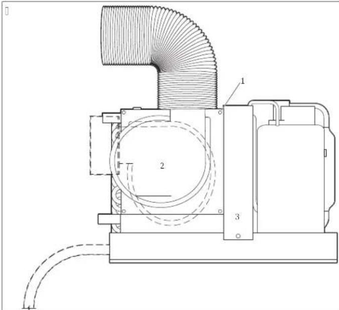
)!creG
2 Numura z.me
6 entilators
J. Nonemiet septinas skrves no pl: ksnes.
2.9agriezietventilatoruvelamaj:poz,cij:
M. Nostipriniet ventilator viet: izmantojot pasksejo:s skruves hny nadrosin: tasf.
6/2/6 DCU(2entilators
A] U sistemas ventiladora rot: cija
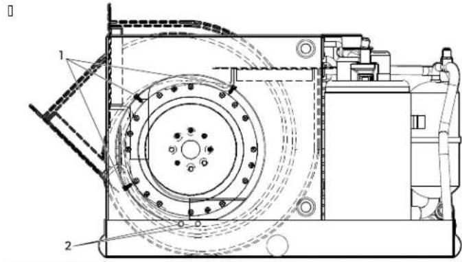
1 creGs on EloGer ring
2 creGs on drain pan or Eracket
J. Iznemiet skrves no ventilatoria gredzena.
2. Izpermiet skruves- ar kur: m ventilators in pieskruvets pie notekteknes vai kronsteina.
M.9agricziet ventilator velamaj: poz, cij:
4. Nostipriniet ventilator viet: izmantojot pas#/ksejo:s skruves knav nodroin: tasl.
P. Aizveriet ar tap: m visus neizmantotos caurumus' lai noverstu gaisa zudumu.
6/6 Gaisa filtr0 05li3yana
Baiswltri likvide dalinas kaE,nes gais: un uztur iztaicet: ja spi: li tru. Ievietojiet vienu gaisa Wtrukar: gaisa kondicationet: j: vai katra gaisa kondicationet: ja atpludes gaisa rezoo
6/9 eqg0 On parelas 3ar, 0 05li3yana
Uzst: dot rezous un p: rejas k: rEash gemiet ver: t: l: k nor: d:to.
Uzst: diet iepludes gaisa rezoi pec iespejas augst: k viet: kas nodrosina vienmer.gu gaisa sadali kaE. n. 9aversiet rezoi riEs uz augsu.
[ Uzst: diet atplides gais rezoi pec iespjas zem: k un tuvu gaisa konditionet: jam lai nodrosin: tu gaisa plumu uz izvaicet: ju.
[ Nevirziet iepludes gaisa plusmu uz atpIedes gaisa reoioj to tas izrais sistemas darEa cikla sa sin: sanos.
[Atst: jiet pietiekamu atstarp starp p: rejas k: rEas iepludes gaisa rezoi un caurulvadu savienojumu. I katiet sadalu | pecik: cijas lpp. 20T
7 U5stadiyana

B IDINAEUMS-Na2eoyae3troyo3ris Uzst:dsan drkst veikt tikai kvalicets elektrikis.
7) Montaqas 3ronyein0 On 3ondensata drenqas 1a0les 05stadiyana

NEMIETVE A- la noverstu notekteknes plais: Sanul neizmantojiet vair: k nek: divus teflona lentes sl: nush lai aptu slutenes uzgalih un nepievelciet slutenes uzgali p: r: k ciesi.
Cipisks mont: Zas kronstein un kondens: ta noteku izvietojums
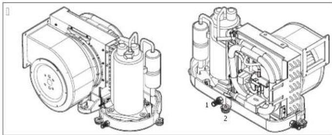
ondens: ta notekas slutenes uzgalis
2 Mont:zas kronsteins
ondens: ta notekas uzst: dSana BcH BaCf HACB un Cf
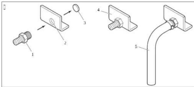
)coseFarE9Arain pan
2 a:tpota dren: Zas atvere: Novadcauules slutiene
6 Izemama detala slutenes ievietoisanai
ondens: ta notekas uzst: d;ana vis: m cit: m gaisa kondiciones anaiercem
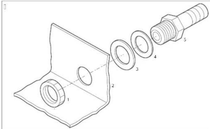
1) locking nut 9! old Gasher
2 Notektekne
9ae uzgalis 0IP in |2R mm e| L 0IP in |2R mm MSCI
LV
6 Skidruma Elvgredzens
J.BCfHBaCfHACB un Cf jercem?
aIzmantojiet [Jutenes uzgala mazo galu: laizemtu detalu no uz aizmuguri pavrst: s dren:zas atveresh pa to vienu reizi uzsitar gumijas: muru. Izmetiet izemamo detalu.
E Apiniet sltenes uzgala v.tnoto galu ar teflona lenti.
cI Jeskruejeiet slutenes uzgali vtopaj: dren:zas caorum: un ciesi pievelciet.
- aisiem citiem gaisa kondictionet: jiem?
aIzE: ziet slutenes uzgali caur cietu pap! ksni un skidrma Elvgredzenu un ievietojet to dren:zas atvere.
Eo Nostipriniet ar sprostuzgriezni.
M. Nostipriniet novadcaurules sluteni pie slutenes uzgala ar nerusejos: terauda slutenes apskavu.
- Izvietojet novadcaurules sluteni virzien: uz leju ldz k: dam droşam un pareizam sav: kşanas punktam.
Mont:zas kronsteina uzst: d;sana B Cf + BaCf + ACB un Cf ier:cem
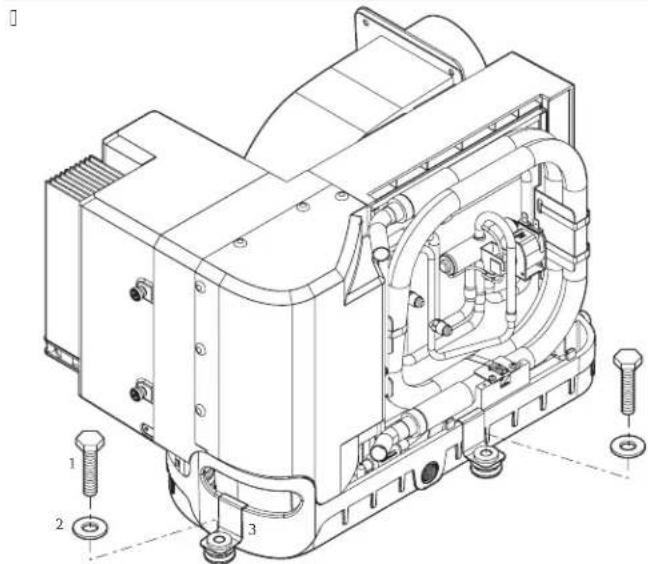
Mont:zas skruiv (nav nodrosin: tal)
2 9api: ksne ar lielu: rejo diametre nodrosin: ta
6 Mont:zas kronsteins nodrosin:
Mont:zas kronsteina uzst d;sana cit: m gaisa kondicioneanas aercem
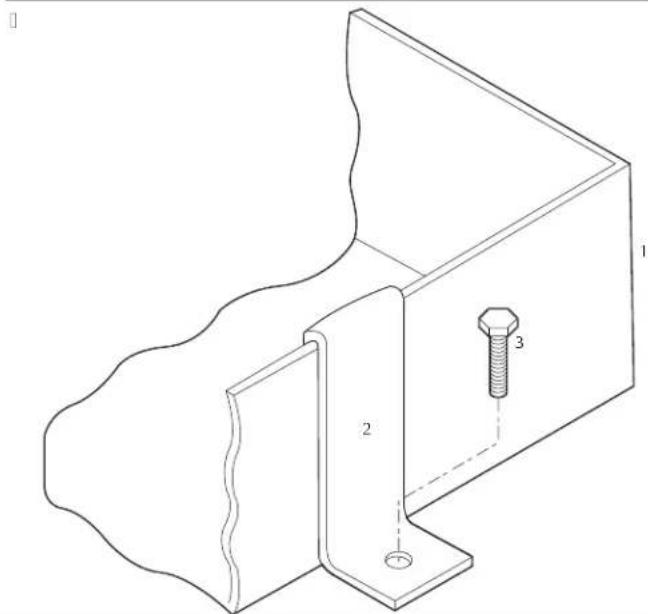
)Notektekne
2 Mont: Zas kronsteins
6 Mont:zas skrive nay nodrosin: ta
P. Uzst: diet vienu mont:zas kronsteinu katr: oliesanas teknes pusé nodrosinot vien: du atstatumu.
9utu materi: la roktura izol: cijas uzst: d'sana BaCf un CF ier;cem
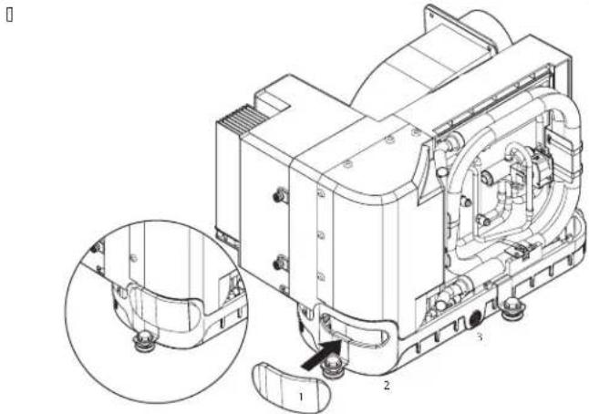
9uto materi: la rokura izol: cija
2 Roktura atverSana
6 Notektekne
ESIET PIESA DCIG! Ugonsdroyi, as apdraOdel0ms
S:ier;ce satur uzliesmojoso izolejoso g:zi.
Ier;ci dr;kst demontet unutilizet tikai speci:lists.

ia iespajams' iepakojuma materi:lus izmetiet atEilstoos atkritumu skiroanas
konteineros. Inform: ciju par produktu utiliz: ciju' trevojot spek: esosos
atkritumu apsaimnkienos noteikumus konsultejieties ar vietjo atkritumu
p:istru:descentu vai specializeto tirgoc.ju.
A Te'nis3ie dati
Izlasiet visus sos nor: djumus un pec tam iep: nojiet savienojumush kas j: izveido pie gaisa kondicationet: ja lostarp pie caurulvada: kondens: ta notekaurules: s: Isudens iepludes un izpludes slutenem EaroSanas avota savienojumiem vad:Eas atrasn: s vietas un s: Isudens sukpa izvietojuma vietas la nadrosin: tu viegli piekluvi izvietosanai un turpm: kajai apkopei.
A/) Da0 atrayanas 2ietas
Baisa kondiconesanasistemaskomponentu identik:cija

) Ieplades gaisa rezoiis un p: rejas k: rEa A' ingstenala slegv: rst
2 Aigit: laie ekr: ns) B! lsudens sieitrns
6! avienojumuk:Fa) !uknis
9 Papildus izvelet: st: Ivad Eas gaisa seno- 2' ondens: ta notekas slutenes uzgalis ra kaEolis
: 1:Isudens izpludes slutene)6 Mont:zas kronsteins
6 Izplades aiz Corta vieta) 9 B aisa kondicionet: js
7! :lsudens iepludes sylute)Atplides gais rezdis un Mtrs
8! :lsudens vienmergas iepludes caurkor 6 Izoletselastgscauruylvads pusu arvere
A/2 Spe1ifi3a1iWas
Aukstumaoenta sistema satur neliu daudzumu videi draudz.gai Et uzliemojosa aukstumaoenta. Cas neEoj: ozona sl: ni un nepalielina silturncas elektu. Nopludes gadjum: aukstumaoenta vars azildegties.
Sis produits satur fluoretas siltumncce'ekta g:zes.
Azesanas iereir hermetiskinoslegta.
Ta, Ola 97: Minimalie 3anala On reqga i5meri at, ilstoyi BTU 3apalitatei
| 6/3 BTU 6 3 BTU 8 3 BTU) | ||||
| Minimilais 3anala diameter | MH00 inMRG2 mm² | 4H00 in||QHO mm² | PH00 in||2Rt0 mm² | QH00 in||P2t4 mm² |
| Minimilais 3anala Sona | QHS injMRT cmj0 | J2H0 injNSjHM cmj0 | JTHO inj||2GP cmj0 | 2SHM inj||S2HQ cmj0 |
| Minimilais aplüdes gaisa reqgis | 4SHO injMMOTR cmj0 | Q4H0 injMj2T cmj0 | S0H0 inj|JPQ2 cmj0 | J00H0 injIC4P-2 cmj0 |
| Minimilais ieplades gaisa reqgis | J210 injMRRH4 cmj0 | M210 inj||2OCHP cmj0 | 4S10 injWOTR cmj0 | G00 injWSRj cmj0 |
| 123 BTU | 63 BTU | 83 BTU | 273 BTU | ||
| Minimailais 3anala dia-metrs | G00 in #P24 mm | R100 in RRMS mm | R100 in RRMS mm | S100 in 20M/2 mm | |
| Minimailais 3anala Sona | 25M inj S21Q cmjC | MSHP inj 24S14 cmjC | MSHP inj 24S14 cmjC | POH inj W24P cmjC | |
| Minimailais atplüdes gaisa reqgis | J00D inj (SMS1S cmj) | J00D inj J02HM cmjC | 200D inj J2T04 cmjC | 240D inj J P4SP cmjC | |
| Minimailais leplüdes gaisa reqgis | R00 inj 4P1Q cmjC | S00 inj P1Q2 cmjC | J00D inj I04P2 cmjC | J 20D inj IRR42 cmjC |
Ta, Ola 98: Udens dar, a temperatura On spiediens
| Minimãã ødens dar, a temperatura | 40-0 [Y 4441] 0 |
| Ma3simãã ødens dar, a temperatura | S00 [Y 2G001] 0 |
| Minimãalais ødens dar, a spiediens | 442 psi 10H2T Ear: 12TH00 k9ac |
| Ma3simãalais ødens dar, a spiediens | C100 psi 104J Ear: 14 k9ac |
Ieverojiet K9A lietosanas nosacjumus.

PIECIME Iek: rta ar samazin: tu jaudu var darEoties ar, citos apst: klos.
B e0ridis3s sat0rs
T13ai CVTX modelui Nai nodrosin: tu atEiistEuIK] C0PNN nepiestipriniet produktu tuv. k k: THS bNN0 m'att: lum: no uzvereja antenas.
)GarantiWa
Inorm: ciju par garantju un garantijas atEalstu Al an: d: un visos p: rejos reionos skatiet l: k esosaj: s sadal: s.
Ameri3as Sa2ienotas Valstis On Kanada
IKRh KZh Cb BARANCIA IR 9IKKAMA aIKCNa hMKCI] hM/KN-UJ/CKRM1-ANA I h NACIN N! -n JUMKRV ARRANCX .A UMI IR 'cAI AUCU.UMI aAI .A.aJAICIK I AZ KCMI'AI I KRh I KZh C: BRANICY.AH 9BtU-AmINIKCIR AR
DOMETIC CORPORATION
MARINE CUSTOMER SUPPORT CENTER
2000 NORTH ANDREWS AVENUE
POMPANO BEACH, FLORIDA, USA 33069
1-800-542-2477
A5iwasOn KloSa o3eana 7APAC, Asia-Pa1ifi8 2alstis
Ja produits nedarEojas k: paredzets sazinieties ar tiringot: ju vai raZot: ja Wli: li sav: valst. skatiet dometic.com/dealeru uusu produitam ir spek: j gadal-uGarantija.
Nosutotier;ci remontam garantjas ietvarsh pievienojiet s: dus dokumentus
[ Čeka kopijur kur: nor: d;ts ieg: des datumis;
[pretenzijasiesniegsanaismesluvaiEoj:jumaaprakstu.
Z emiet ver: ka paROC:gi vai neprolesion: li veikts remonts var rad; t gros;Eas riskush un garantija var tikt anuleta.
Ti3ai A0stralila
Mûsu precem ir garantijāk kuru ndr;st izslogen saskan: ar Austr. lijas pateret: ju ties;Eu norm: m. ums ir ties:Eas uz uz nomaipu vai naudas agtriesan par Ettiskiem dektiem un uz kompens: ciju par citiem pamatoti paredzamiem zaudejumiem vai Eoj: jumiem. ums ir ar; ties:Eas piepras; preCu remontu vai nomainul ja preCu kvalit: te ir nepienemama! Et et dekti nav uzskat: mi par Ettiskiem dektiem.
Ti3ai eao5elande
Uz so garantju atticcin: mi noteikumi un garantijas+kas noteiktas k: oElig: tas | TTM. gada 9ateret: ju garantju likum: Nm
Visiparelie regioni
Ir spek: likum: noteiktais garantijas periods. 9rodukta Eoj: jumu gad.jum: szinieties ar ražot: ja Wli: li sav: valst: skatiet dometic.com/dealer vai tirgot: ju.
Nosutot ier;ci remontam garantijas ietvaros' pievienojiet dus dokumentus?
dometic.com/sales-offices

- Copyright' t
- Englis
- Important notes
- Explanation of sym, ols
- 2/) S0plementale dire1ti2es
- 2/2 Safety instr01tions
- EN
- Target groOp7s8
- Intended 0se
- Explanation of sym, ols on t'e de2i1e
- Pre-installation
- 6/ Determining t' e installation lo1ation
- 6/2 otating t' e, lower
- #
- 6/6 Plaing t' e air filters
- 6/9 Plaing t' e grilles and transition, oxes
- Installation
- 7/) Installing t' e moOnting, ra13ets and Iondensate drain
- 7/2 Installing t' e d01ting
- 7/6 Installing t' e seawater system
- 7/9 Ma3ing eletrilal lonneltions
- NOTICE
- Disposal
- CAUTION-Fire a5ard
- A Tel'nilal data
- A/) Part lotations
- A/2 Speliliflations
- B Legal
- ). arranty
- United States and Canada
- Asia-Palifi7APAC81oOntries
- Australia Only
- New Cealand only
- All ot'er regions
- De0ts1
- 2/2 Si' er' eits' inweise
- LDnder im a0m Asien4Pa5ifi3 7APAC8
- 2/2 Consignes de sL10ritL
- A/! Lo1ali5ajoes das pej as
- A/2 Espelifiljoes
- Todas as o0tras regioes
- 2/2 Istr05ioni per la si10re55a
- Pre-installal5ione
- AVVISO
- 2/2 Veilig' eidsaanwil5ingen
- 7/9 Ele3tris' e 2er, indingen ma3en
- 2/2 Si33er'eds' en2isninger
- DA
- A/) Delenes pla1ering
- A/2 Spe1ifi3ationer
- 2/2 SD3er'etsan2isiningar
- 2/2 Si33er'etsinstr03sVoner
- ADVA SEL-Fare for ele3tris3 stct
- Gelder 30n for New Cealand
- Alle andre regioner
- 2/2 Tor2allis00s'Vect
- 2/2.s3a5sW3i,e5pie15enstwa
- 2/2 Be5pevnL po3yny
- SK
- VsST AHA-Ne, e5pevenst20 2w, 01'0
- VsST AHA-Ne, e5pevenst2o 5Xsa'0 ele3tri13wm prudom
- POCO
- POCO -
- Ciexo2L s30piny
- Po0qT2anie 2{sulade sOrvenTm
- : Vys2etlenie sym, olo2 na(5ariaden
- 2/2 Be5pevmostn1 po3yny
- 6/2/2 VentilXtory MCS, ECD aGT
- 6/6 VloqenT 25d01' o2w1' filtru
- 6/9 UmIsten mIq3 a(p) odo2w1 s3fne3
- 7Instala1e
- 7/InstalaemontXqnT3on5ol aod2od0 3onden5XtO
- CS
- Refrigerant Safety Group A2L
- 6CilVne s30pine
- NamVena
- UgA I-gangin 2eya patlama ris3i
- galm51a geni Celanda
- TEmdiger, Hlgeler
- 2/2 Vamostni napot3i
- RO
- :O6aCHeHHe Ha cIMB0JIHTe Bbpxy ypeJa
- 6IeJIeBa7n8 rpyna7n8
- N3noJ3BaHe no nppeHa3HaueHne
- 6jOIOTOBka3aMOHTaK
- 6/OnpeJeIeHaMaCToToHaMOHTaK
- 6/2 3abpbTaHe Ha BeHTHaToppa
- 6/2) BeHTnlaTOpHa GTX, GVTX, DTG n TX
- 6/2/6 BeHTHJatop Ha DCU
- 6/6octabHHe Hb3dyHHTe HnItpn
- 6/9 octabane Ha peWetKHTe H npexoDHTe Kyttn
- INHCTaJInpaHe
- 7/ MoHTnpaHe Ha MOHTaKHNTE CkO6n H npEpaKa 3a KOHJeH3AT
- BG
- 7/2 MoHTnpaHHe Ha Bb3dYxOBQDHTe
- 7/6 HcTaIpaH He cHCTeMaTa 3a MOpcka BOda
- 7/9 OcbueCTBBAHHe Ha eJektpnueckn Bp3kn
- iPEyjPEKJEHNE-OtacHOCTOTOKOByap
- BHIMAHNE
- INxBbprJHe
- BHIMAHHE-OnachOCTornoKap
- A TexHHueckn daHHN
- A/MeCToIIOJIOKeHHaHaCTH
- A/2 Cneu#kaaun
- B3aKoHHa
- )TapaHnna
- CAUH(Kanada
- IbPkaBn O T AHaTcKo-TNXOKeaHcknpeHHOH 7APAC8
- Cama 3a Abcptpann
- BcunKIOCTaHaJIpeHNOH
- Eesti 3eel
- 1) Ololised mDr30sed
- SEm, olite selgitOs
- 2/2 Ynoδεiεicασφaλεiac
- KINADYNOI KIVSUVOC TUPKAYIACn EKPNEnC. OpiuEva movTeAa XpOIOLOUv EoAekTo yukTKo Meo.
- NPOEIDONIOIH! Kivduocupkayiac/kai ekpn
- NPOEIONOIHSH! KivSuvocIywo mvoEoiouavpaka
- NPOEIOONIH! KivduvoocAekptponnxiac
- IPOEIOIOIHsH! KivouocnAektpoanxiac, Tupkayiac/Kaekpns
- NPOEIOONIH KivSuvocekpn
- NPOEIODOIHEN! KivduocnAektonnxiac
- PPOEOXH!
- Omaδa(-εc) στóxol
- 6/2/6 DCU 2entilatoriOs
- 2/2 Droyi, as norades
- BISTAMI! Ugonsgre3a 2ai sprad5iena ris3s/ Daqos modelos tie3 i5mantots 05iesmofoys a03stOmagents/
- B ID!NAeUMS-UgOns,Istami,a On42ai sprad5ien,Istami,a
- B IDINAAUMS-Ogle3ja mono3sida radits apdra0delloms
- B ID!NAeUMS-Na2cOya cte3troyo3a ris3s
- B ID!NAeUMS-Ele3tris3as stra2as tric1iena,0gOnsgre3a On42ai sprad5iena ris3s
- 6/2/6 DCU(2entilators
- 6/6 Gaisa filtr0 05li3yana
- 6/9 eqg0 On parelas 3ar, 0 05li3yana
- U5stadiyana
- 7) Montaqas 3ronyein0 On 3ondensata drenqas 1a0les 05stadiyana
- LV
- Skidruma Elvgredzens
- A Te'nis3ie dati
- A/) Da0 atrayanas 2ietas
- A/2 Spe1ifi3a1iWas
- B e0ridis3s sat0rs
- )GarantiWa
- Ameri3as Sa2ienotas Valstis On Kanada
- A5iwasOn KloSa o3eana 7APAC, Asia-Pa1ifi8 2alstis
- Ti3ai A0stralila
- Ti3ai eao5elande
- Visiparelie regioni
Brand : DOMETIC
Model : Cuddy DC II
Category : Air Conditioning