
SinePower DPSI424 - Battery charger DOMETIC - Free user manual and instructions
Find the device manual for free SinePower DPSI424 DOMETIC in PDF.
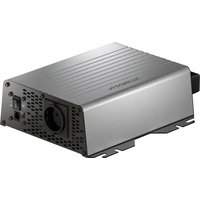
| Product type | Pure sine wave inverter |
| Brand | Dometic |
| Model | SinePower DPSI424 |
| Nominal input voltage | 24 V DC |
| Output voltage | 230 V AC |
| Continuous output power | 300 W |
| Maximum output power (1 min) | 600 W |
| Surge power (2 s) | 1200 W |
| Waveform | Pure sine wave |
| Output frequency | 50 Hz |
| Maximum efficiency | 90% |
| Operating temperature range | 0 °C to 40 °C |
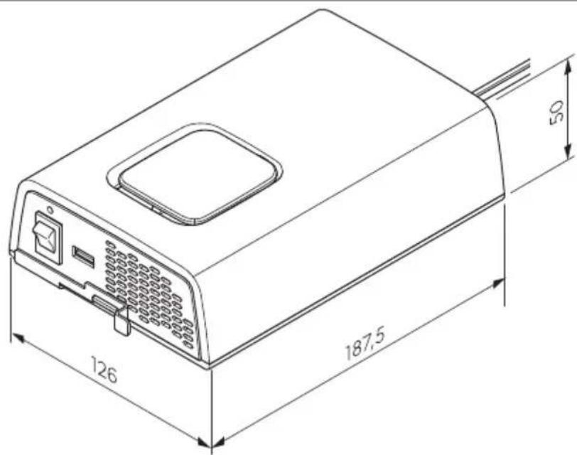
| Dimensions (L x W x H) | 126 x 187.5 x 50 mm |
| Weight | 1.09 kg |
| Integrated protections | Overvoltage, undervoltage, overtemperature, overload, short circuit |
| Connectivity | AC power outlet, USB port, external switch connection |
| Intended use | Leisure vehicles, stationary or mobile use, indoor |
| Delivery contents | Inverter, mounting plate, fixing kit, instructions |
| Cleaning | Damp cloth, do not immerse |
| Warranty | Legal warranty |
Frequently Asked Questions - SinePower DPSI424 DOMETIC
User questions about SinePower DPSI424 DOMETIC
0 question about this device. Answer the ones you know or ask your own.
Ask a new question about this device
Download the instructions for your Battery charger in PDF format for free! Find your manual SinePower DPSI424 - DOMETIC and take your electronic device back in hand. On this page are published all the documents necessary for the use of your device. SinePower DPSI424 by DOMETIC.
USER MANUAL SinePower DPSI424 DOMETIC
natural_image
Line drawing of a device with a cable and connector, no text or symbols present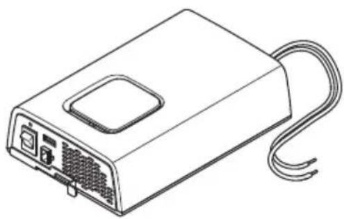
natural_image
Line drawing of a rectangular electronic device with ports and cables (no text or symbols)SinePower DPSI212, DPSI224, DPSI412, DPSI424
EN
Sinewave inverter
Installation and Operating Manual..... Y
DE
Sinuswellen-Wechselrichter
Montage- und Bedienungsanleitung...... I R
FR
Onduleur sinuso dal
Instructions de montage et de service....KV
ES
Inversor de onda sinusoidal
Instrucciones de montaje y de uso.... RT
P!
Inversor de onda sinusoidal
Instruções de montagem e manual de instruções.....TQ
I!
Inverter a onda sinusoidale
Istruzioni di montaggio e d'uso..... UY
NL
Sinusomvormer
Montagehandleiding en gebrui saan! ijzing......VJ R
DA
Sinusbøl' einverter
Monterings- og betjeningsvejledning...... VI V
s(
Sinusv) xelriktare
Monterings- och bru sanvisning......VQT
NO
Sinusvekselretter
Monterings- og bru sanvisning.... VRO
FI
Sini-vaihtosuuntaa,a
Asennus- ja äyttöohje.... VSY
PL
Pr-etwornica sinusoidalna
Instru cja montasu i obsługi......VUR
S.
S/nusov0 meni1 na2) tia
' (vod na mont() a uvedenie do prev(dz y.....| J V
3S
4 5ni1 se sinusov0m 2r6b5hem
'(vod mont() i a obsluze....I VT
78
S-inus-hull9mos inverter
H I J I K L ometic Mroup. Nhe visual appearance o ^0 the contents o ^0 this manual is protected by copyright and design la! . Nhe underlying technical design and the products contained herein may be protected by design ^2 patent or pending patent. Nhe trademarks mentioned in this manual belong to L ometic S! eden AB. All rights are reserved.
List oP Fi' ures

□
B
□

□

□
DPSI 2xx
□
DPSI4xx
DPS1412: 50 A
DPSI424: 25 A
□
DPSI 4xx

□
□
natural_image
Line drawing of a device with an attached cable and connector, showing ports and wiring (no text or symbols)□
En' lish
V Important notes....Y
I Wxplanation of symbols.... Y
Q Safety instructions....VJ
K Scope o ^3 delivery....VQ
R Intended use....VQ
S Technical description....VK
T Installation....VS
U Operation.... IV
Y Zleaning and maintenance....|
VJ Nroubleshooting......
W Warranty....I Q
VI L isposal.... I Q
VQ Technical data.... I K
1 Im2ortant notes
Please read these instructions carefully and Collo! all instructionsf guidelines? and ! arnings included in this product manual in order to ensure that you installP useF and maintain the product properly at all times. These instructions M. SN stay ! ith this product.
By using the product, you hereby confirm that you have read all instructions ^§ guidelines ^2 and ! arnings carefully and that you understand and agree to abide by the terms and conditions as set forth herein. You agree to use this product only for the intended purpose and application and in accordance! with the instructions ^§ guidelines ^2 and ! arnings as set forth in this product manual as ! ell as in accordance! with all applicable la! s and regulations. A failure to read and collo! the instructions and ! arnings set forth herein may result in an injury to yourself and others ^§ damage to your product or damage to other property in the vicinity. This product manual including the instructions ^§ guidelines ^2 and ! arnings ^§ and related documentation ^2 may be subject to changes and updates. For up-to-date product information ^§ please visit documents.dometic.com.
2 Ex2lanation oP sNmbols
A signal ! ord ! ill identify safety messages and property damage messagesP and also ! ill indicate the degree or level of hazard seriousness.

DANGERQ
Indicates a hazardous situation that ^p is not avoided ^p ! ill result in death or serious injury.

WARNINGQ
Indicates a hazardous situation that ^P i ^C not avoided ^P could result in death or serious injury.

3A8! IONQ
Indicates a hazardous situation that ^P is not avoided ^P could result in minor or moderate injury.

NO! I3EQ
Indicates a situation that P i0 not avoidedP can result in property damage.

NO! E Supplementary information for operating the product.
R SaPetN instructions
Also observe the saPetN instructions and sti2ulations issued bN the vehicle manuPacturer and authori-ed worksho2s\$
RS1 General saPetN

DANGERQ Electrocution ha-ard
L o not touch exposed cables ! ith your bare hands.
No be able to disconnect the device quickly from the AZ po! er supply? the soc et must be close to the device and be easily accessible.

WARNING Electrocution hazard
Installation and removal of the device may only be carried out by qualified personnel.
L o not operate the device i0 the device itsel0 or the connection cable is visibly damaged.
I do this device's po! er cable is damaged? the po! er cable must be replaced in order to prevent safety hazards.
This device may only be repaired by qualified personnel. Improper repairs can lead to considerable hazards.
Only use accessories that are recommended by the manufacturer.
L o not modify or adapt any of the components in any ! ay.
L o not disconnect any cables ! hen the device is still in use.
L isconnect the device from the po! er supplya
b Acer use
b Before each cleaning and maintenance
b Before changing a fuse

WARNINGQ Fire ha-ardTFlammable materials
In event of fire use a fire extinguisher! which is suitable for electrical devices.

WARNINGQ Risk oP as2hNxiation
The cable and control unit of the device can give rise to rise an entanglement strangulation tripping or treading not correctly arranged. Ensure that excess ties and po! er cables shall be arranged in a safe ! ay.

WARNINGQ 7 ealth ha- ard
This device can be used by children aged from U years and above and persons ! ith reduced physical sensory or mental capabilities or lac o0 experience and no! ledge i0 they have been given supervision or instruction concerning use o0 the device in a sale ! ay and understand the hazards involved.
Electrical devices are not toNs\$ All ays eep and use the device out o0 the reach o0 very young children.
Z children must be supervised to ensure that they do not play! ith the device.
Z leaning and user maintenance shall not be made by children! without supervision.

NO! I3E0 Dama' e ha-ard
Before start-up? check that the voltage specification on the data plate is the same as that of the power supply.
Wnsure that other objects cannot cause a short circuit at the contacts of the device.
Wnsure that the negative and positive poles never come into contact.
L o not pull on the connection cables or use the cables as a handle.
The device must not be exposed to rain or moisture. Store in a dry place.
RS2 Installin' the device saPelN

DANGERQ Ex2losion ha-ard
Only install and operate the device in closed ^p ! ell-ventilated rooms.
L o not install or operate the device under theollo! ing conditionsa
b In salty ^P ! et or damp environments
b In the vicinity of corrosive 0umes
b In the vicinity of combustible materials
b In the vicinity of heat sources cheaters direct sunlight gas ovens etc.
b In areas! here there is a ris o gas or dust explosion

WARNINGQ Risk oP in, urN
Wnsure that the device is standing firmly. Nhe device must be set up and 0astened in such a ! ay that it cannot tip over or call do! n.
When positioning the device ensure that all cables are suitably secured to avoid any form of trip hazard.

NO! I3E0 Dama' e ha-ard
Dlace the device in a dry location! here it is protected against splashing! later.
Al! ays use soc ets ! hich are grounded and secured by residual current circuit brea ers
RSR SaPetN when connectin' the device electricallN

DANGER Electrocution hazard
To you are ! or ing on electrical systems? ensure that there is somebody close at hand! ho can help you in emergencies.

WARNING Electrocution ha-ard
Observe the recommended cable cross-sections.
fay the cables so that they cannot be damaged by the doors or the hood. Z rushed cables can lead to serious injury.

NO! I3EQ Dama' e ha-ard
. se duct! or or cable ducts it is necessary to lay cables through metal panels or other panels! with sharp edges.
L o not lay the | Q| g mains cable and the VI g L Z cable in the same duct.
L o not lay the cable so that it is loose or heavily in ed.
Fasten the cables securely.
RS4 SaPetN 2 precautions when handlin' batteries

WARNINGQ Risk oP in, urN
Batteries contain aggressive and caustic acids. Avoid battery huid coming into contact ! ith your body. I0 your s in does come into contact ! ith battery huid! ash that part o0 your body thoroughly ! ith ! ater. I0 you sustain any injuries from acids? contact a doctor immediately.
When ! or ing on batteriesP do not ! ear any metal objects such as ! atches or rings. fead acid batteries can cause short circuits ! hich can cause serious injuries.
Only use insulated tools.
L o not place any metal parts on the battery and prevent any metal parts from calling on the battery. Nhis can cause spars or short-circuits the battery and other electrical devices.
Wear goggles and protective clothing! hen! or ing on batteries. L o not touch your eyes! hen! or ing on batteries.
Only use rechargeable batteries.
L o not use defective batteries.

3A8! IONQ Ex2losion ha-ard
' ever attempt to charge a frozen or defective battery. Dlace the battery in a Orost-Oree area and ! ait until the battery has acclimatised to the ambient temperature. Nhen start the charging process.
L o not smo e ^p use an open hame ^p or cause spar ing near the engine or a battery.
/eep the battery a! ay from heat sources.

NO! I3EQ Dama' e ha-ard
Wnsure that the polarity is correct! hen connecting the battery.
Follo! the instructions o0 the battery manufacturer and those o0 the manufacturer o0 the system or vehicle in ! hich the battery is used.
To the battery has to be removed first disconnect the ground connection. L isconnect all connections and all consumers from the battery before removing it.
Only store Fully charged batteries. i echarge stored batteries regularly.
L o not carry the battery by its terminals.
RSU O2eratin' the device saPelN

WARNING Electrocution hazard
L o not use the device in ! et conditions or submerge in any liquid.
Before starting the device ensure that the power supply line and the plug are dry and the plug is free from rust or dirt.
Observe that parts of the device may still conduct voltage even i0 the 0use has blo! n.

NO! I3EQ Dama' e ha-ard
Wnsure that the air inlets and outlets of the device are not covered.
Wnsure a good ventilation.
4 Sco2e oP deliverN
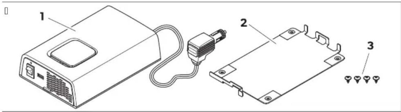
| No$ inon 2a' e01R | Desi' nation VuantitN |
| V Sine ! ave inverter V |
| I Mounting plate V |
| Q Fixing scre! s K |
| j Installation and operating manual V |
U Intended use
Nhe inverter is intended to convert direct voltage into a pure sine ! ave | QJ g\~ alternating voltage dAZe for operation and stable po! er supply o0 connected | QJ g consumers.
Nhe inverter is intended for connection toa
b L DSII I KP L DSIKI Ka I Kg
Nhe inverter is suitable 3ora
b Installation in recreational vehicles di ge
b Stationary or mobile use
b Indoor use
Nhe inverter is not suitable 0ora
b Outdoor use
This product is only suitable for the intended purpose and application in accordance! with these instructions.
This manual provides information that is necessary for proper installation and/or operation of the product. Door installation and/or improper operation or maintenance will result in unsatisfactory performance and a possible failure.
The manufacturer accepts no liability for any injury or damage to the product resulting croma
b Incorrect installation ^p assembly or connection ^p including excess voltage
b Incorrect maintenance or use of spare parts other than original spare parts provided by the manufacturer
b Alterations to the product ! without express permission from the manufacturer
b. se for purposes other than those described in this manual
L ometic reserves the right to change product appearance and product specifications.
W! echnical descri2tion
WS1 General descri2tion
Nhe inverter is a L Z-to-AZ sine! ave inverter.
Nhe inverter has the 0ollo! ing protective mechanismsa
b Overvolta' e shutdown: Nhe inverter s! itches ol ! hen the voltage exceeds the cut-ol value. Nhe inverter restarts automatically ! hen the voltage drops to the restart value.
b 8ndervolta' e shutdown: Nhe inverter s! itches ol ! hen the voltage calls belo! the cut-ol value. Nhe inverter restarts automatically ! hen the voltage exceeds the restart value.
b 7i' h tem2erature shutdown: Nhe inverter s! itches ol ! hen the internal temperature o0 the device exceeds the cut-ol value. Nhe inverter restarts automatically ! hen the internal temperature drops to the restart value.
b 7i' h out2ut current 2rotection: Nhe inverter s! itches ol ! hen too many loads are connected.
b Protection a' ainst short circuit: Nhe inverter s! itches ol ! hen a short circuit has been generated. Nhe inverter restarts automatically acer a 0e! seconds. I0 a short circuit is detected or five consecutive times ^9 the inverter does not restarts automatically and a manual restart is needed.
DPSI412, DPSI424 onlN: Nhe inverter can be connected to an external s! itch to be used as a remote control.
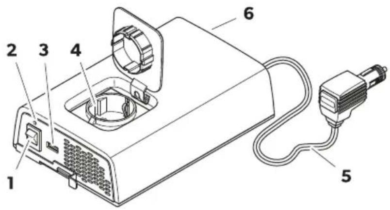
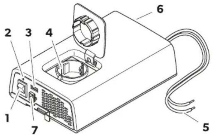
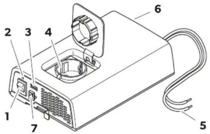
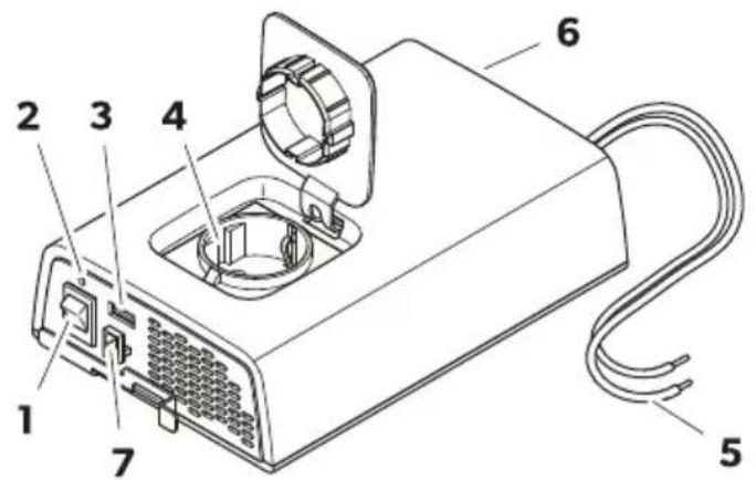
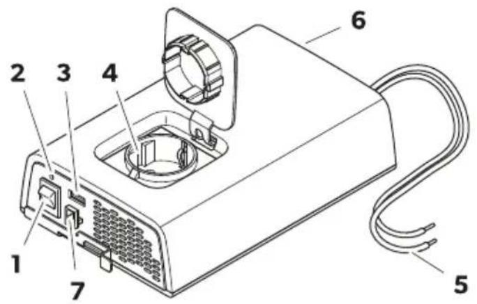
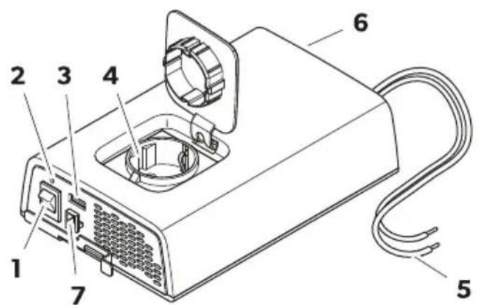
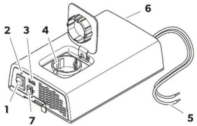
WS2 3ontrol elements and connections
□
DPSI 2xx
DPSI 4xx
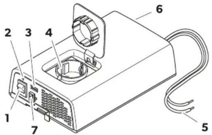

NO! E Fig.10 on pageVR sho! s the version 0or continental Wurope.
| No$ inon 2a' e01U | Desi' nation |
| V Onkol s! itch | |
| I Status indication fWL | |
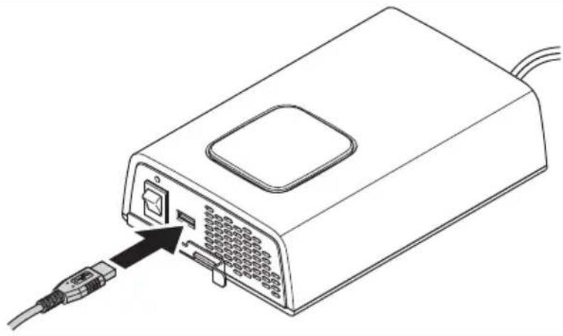
| Q. SB output | |
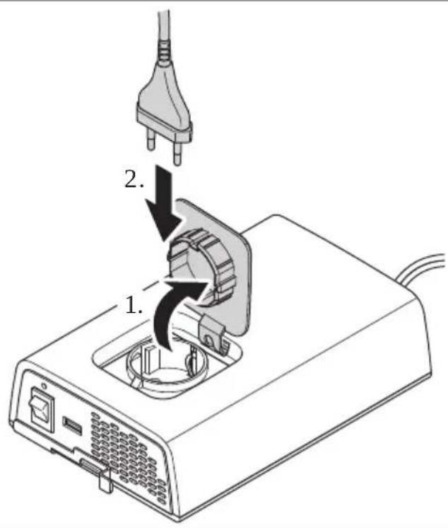
| K AZ outlet | |
| R L Z connection cable | |
| S Fan | |
| T DPSI412, DPSI424 onIN: Wxternal s! itch connection |
WSR Status indication LED
| Status Descri2tion |
| On Inverter operation |
| Flashing Wrror dsee chapter Nroubleshooting on pageII e |
| O| ' o AZ input present ^p inverter deactivated |
Y Installation
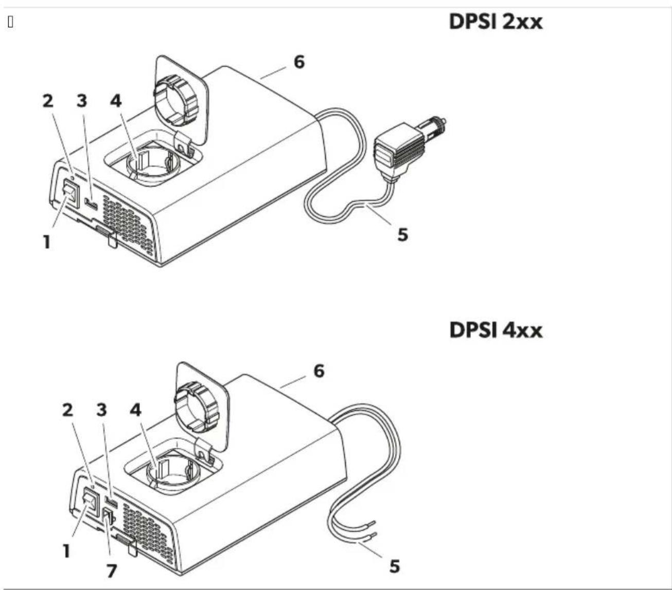
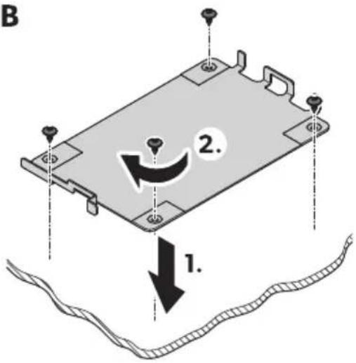
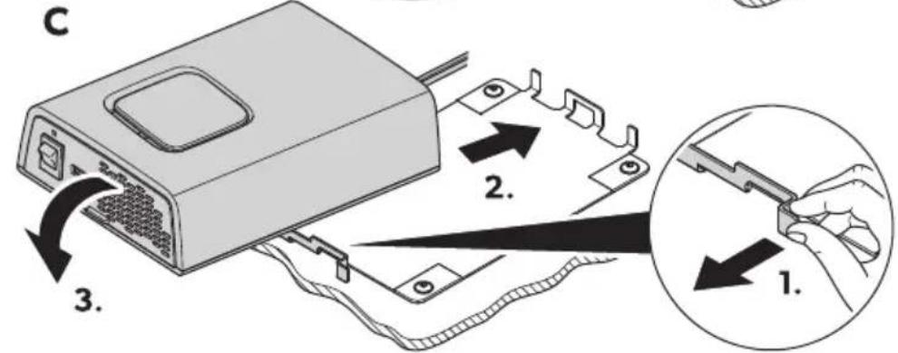
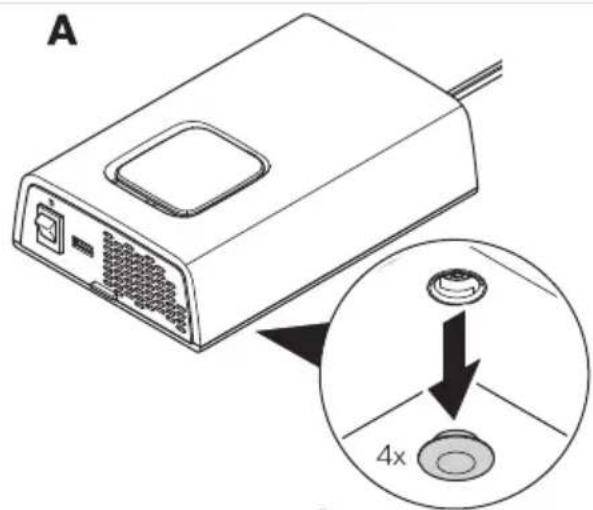
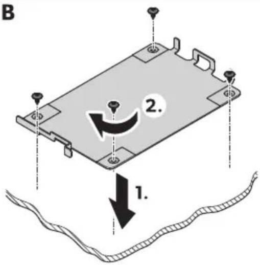
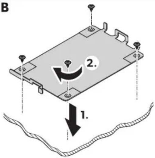
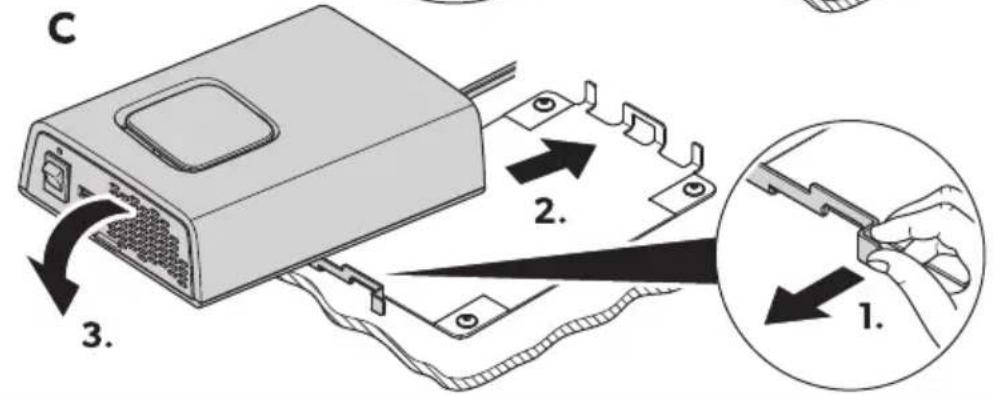
YS1 4 ountin' the inverter
□
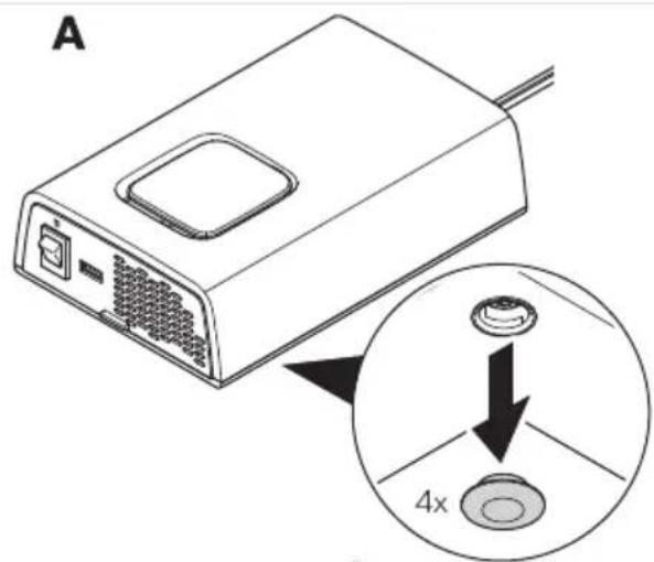


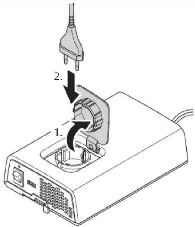
V. foosen the caps on the underside o0 the device d Fig.10 on page VSP Ae.
1. Scre! the mounting plate in place d Fig.10 on page\VSP Be.
Q. Attach the device to the mounting plate d Fig.10 on pageIVSP 3e.
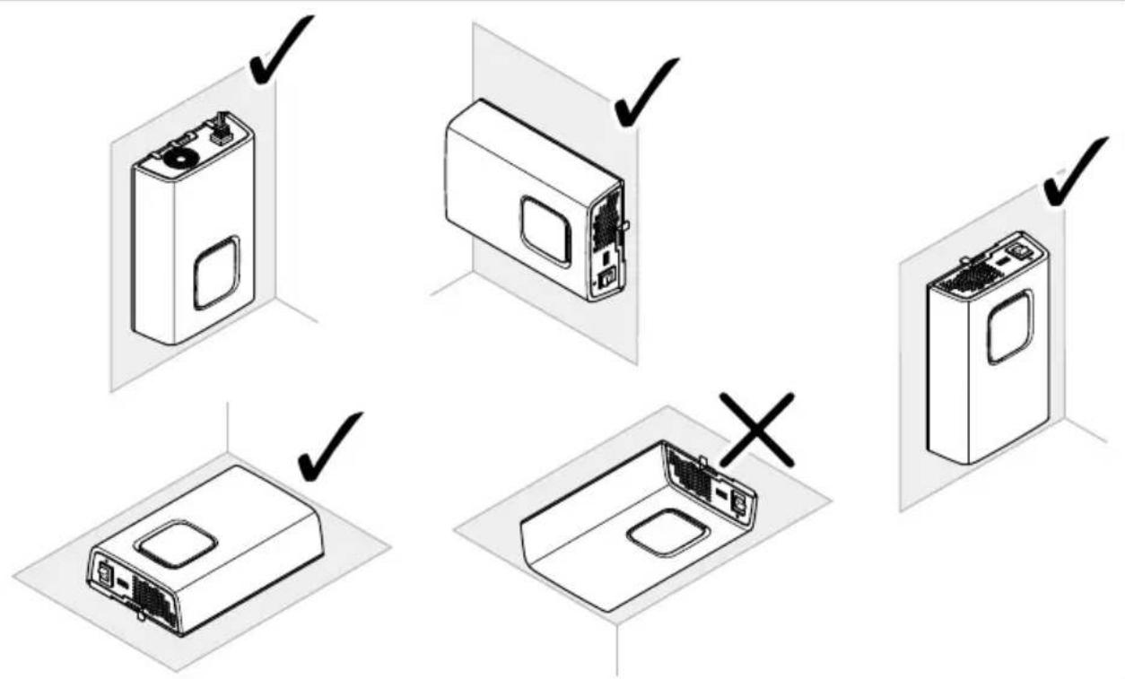
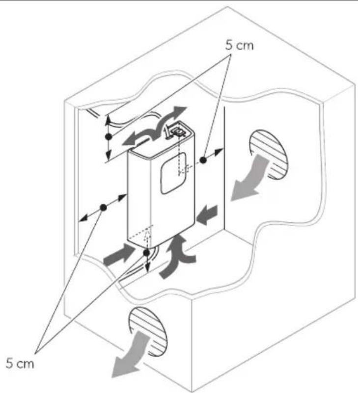
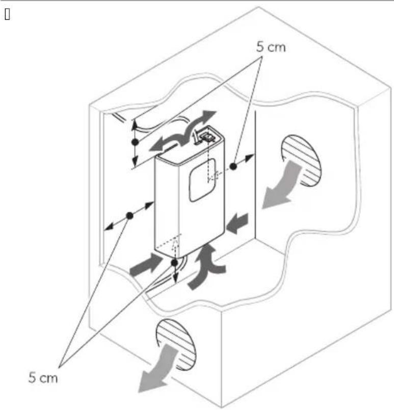
YS1S1 Installation location
□


NO! I3EQ Dama' e ha-ard
Before drilling any holes ^2 ensure that no electrical cables or other parts of the vehicle can be damaged by drilling ^3 sa! ing and filing.

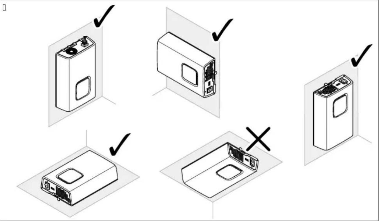
NO! E
The inverter can be mounted either sitting or hanging c [IMAGE] Fig.10 on pageIVTe.
[]

Observe the collo! ing instructions ! hen selecting an installation locationa
b Wnsure that the mounting surface is solid and level.
b Observe the distance specifications for sufficient ventilation of Fig.10 on pageWUe.
YS2 3connectin' the inverter
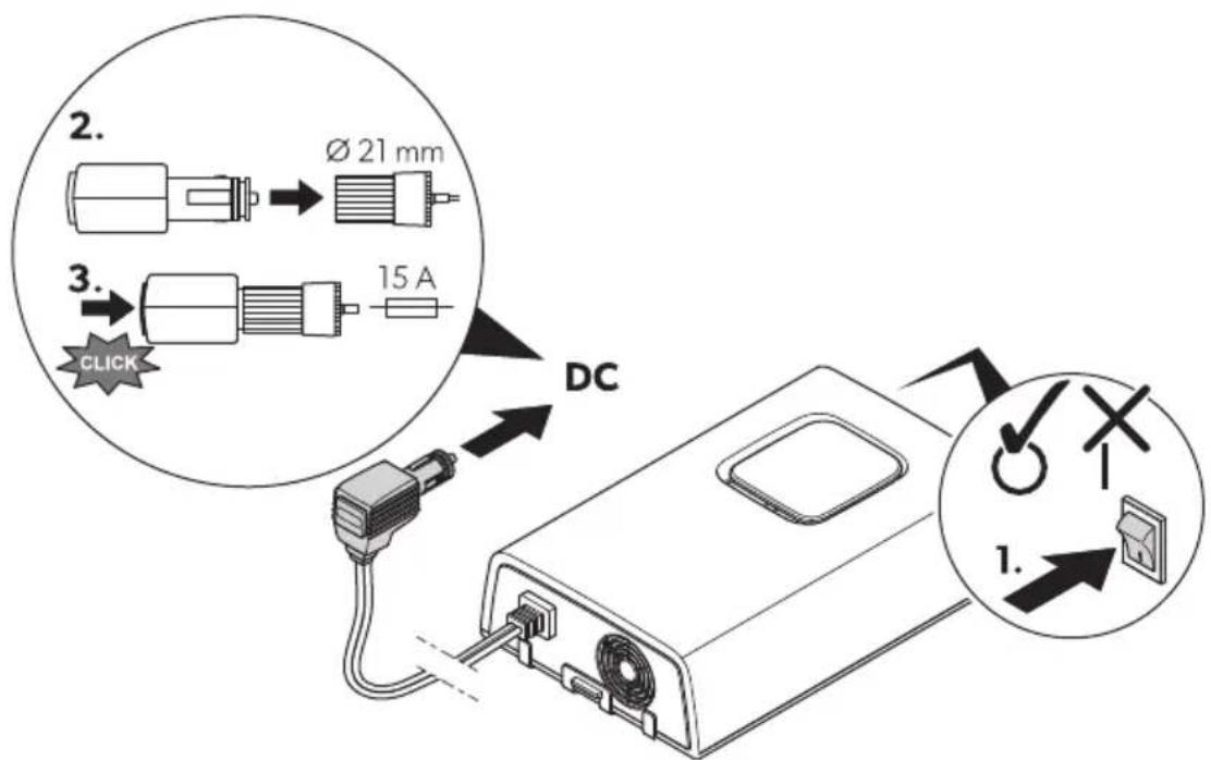
DPSI212, DPSI224
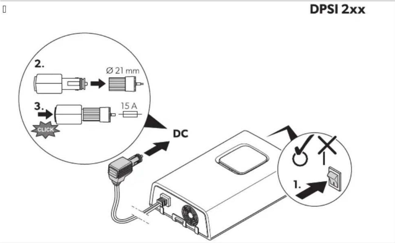
V. Zhec that the device is s! itched ol.
- Zonnect the po! er cable to the cigarette lighter soc et o0 the vehicle.
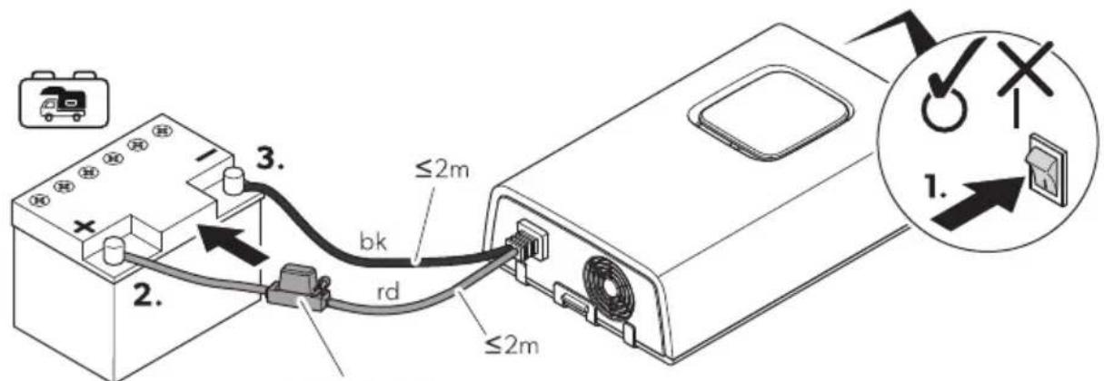
DPSI412, DPSI424

WARNING Electrocution ha-ard
Observe the recommended cable cross-sections ^p cable lengths and 3used 4 fig. 1 on pagell J e.

3A8! IONQ Fire ha-ard
Dlace the uses near the batteries to protect the cable from short circuits and possible burning.

NO! I3EQ Dama' e ha-ard
Observe the connection sequence of the connection cables to avoid short-circuiting the device.
L o not reverse the polarity.
Protect the positive cable of the house battery! ith a 0use d Fig.10 on page1 J e.
□
DPSI4xx
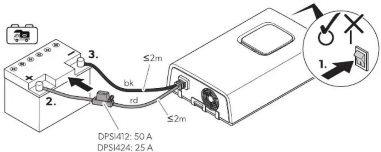
V. Zhec that the device is s! itched o|.
- Zconnect the blac db e connection cable to the negative terminal o0 the house battery d Fig.10 on pagell J P Re.
Q. Zonnect the red drde connection cable to the positive terminal o3 the house battery d Fig.10 on pagell J P 2e.
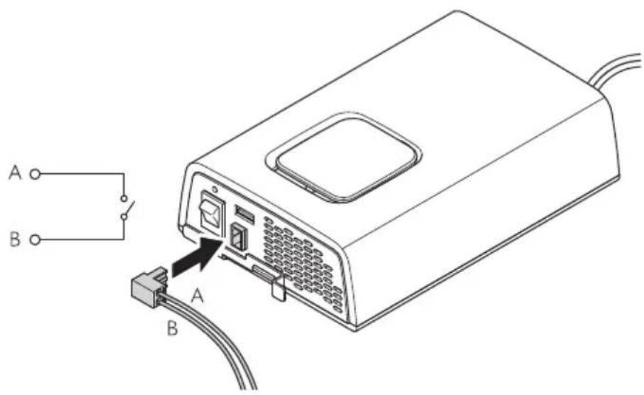
YSR 3connectin' the external switch ZDPSI412, DPSI424 onlN)
□
DPSI 4xx
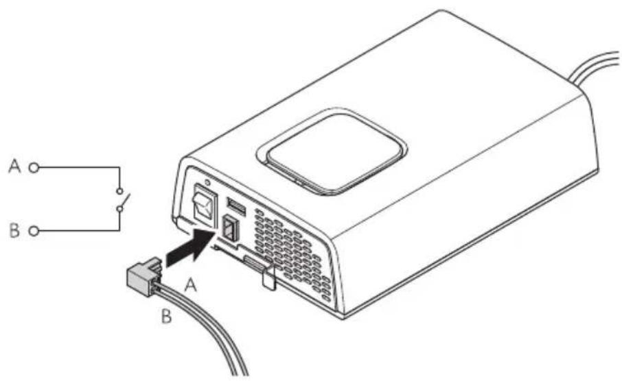
Zconnect the external s! itch to the external s! itch connection d Fig.10 on pagell J e.
8 O2eration
8\$1 O2eratin' 2R0 ( devices
□

NO! E
Only connect devices! hose total load does not exceed the values listed in Technical data on page1 K.
V. Zconnect the inverter see chapter Zconnecting the inverter on pageIVYe.
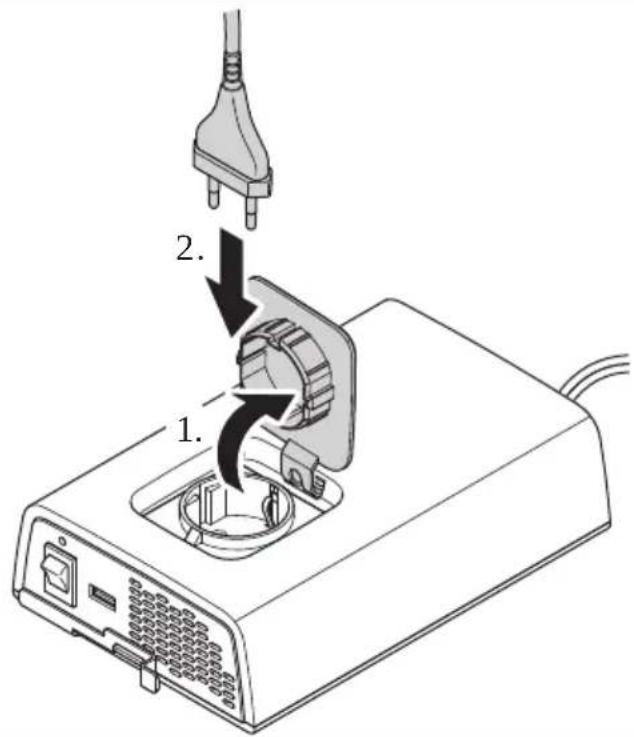
- Zconnect | QJ g devices to the AZ outlet of the inverter d Fig.10 on page 1 Ve.
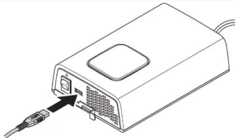
8\$2 3har' in' via 8SB
[]

natural_image
Line drawing of a device with an attached cable and connector, showing ports and wiring (no text or symbols)Zconnect the rechargeable device to the . SB terminal d Fig.10 on pagell Ve.
8SR Switchin' the inverter on and oPP

NO! E. I' the inverter is to be controlled via the external s! itch ^p the onkol s! itch must be set to position 0.
No s! itch on the inverterP set the onkol s! itch to position l.
No s! itch of the inverter ^p set the onkol s! itch to position 0.
DPSI412, DPSI424 onlN: . se the external s! itch to s! itch the inverter on and ol.
9 3leanin' and maintenance

WARNING Electrocution ha-ard
. nplug the device from the power supply before cleaning and maintenance.

NO! I3EQ Dama' e ha-ard
' ever clean the device under running ! ater or in dish ! ater.
L o not use sharp or hard objects ^2 abrasive cleaning agents or bleach during cleaning as these can damage the device.
Wnsure that the air inlet and outlet vents o0 the device are 0ree o0 dust and dirt so that the heat can be released.Occasionally clean the device ! ith a soc ^p damp cloth.
i egularly chec live cables or lines for insulation faults ^p breas or loose connections.
10 ! roubleshootin'
| Problem Possible cause Su' ested remedN | ||
| Nhe inverter does not ! or . Nhe status indication fWL is ol. | Short circuit has been generated. Nhe device use must be replaced by an authorized service agent after it has been triggered by excess current. | |
| InsulationaultsP breas or loose connections at the live cables. | > Zhec live cables or insulationaultsP breas or loose connections.10 you cannot find an error? contact an authorized service agent. | |
| Nhe inverter does not ! or . Nhe status indication fWL clashes slo! ly. | n igh output current protection. | i educe the connected loads. |
| n igh temperature shutdo! n. | V. S! itch ol the inverter and the connected loads.I . Zhec that the air inlets and outlets are not covered or obstructed.Q. Allo! the inverter to cool do! n. | |
| Short circuit has been generated. | Nhe device use must be replaced by an authorized service agent after it has been triggered by excess current. | |
| Problem Possible cause Su^ ested remedN | ||
| Nhe inverter does not ! or . Nhe status indication fWL clashes quic ly. | Overvoltage shutdo! n i educe the connected voltages. | Nhe inverter restarts automatically-ly ! hen the voltage drops to the restart value c ≤ J ge.> I0 the error still occurs Increase the cable cross-sections. i educe the cable length. |
| ndervoltage shutdo! n. Allo! the battery to recharge slo! -ly.Nhe inverter restarts automatically-ly ! hen the voltage exceeds the restart value. | ||
11 WarrantN
The statutory ! arranty period applies. It the product is defective ^® please contact the manufacturer's branch in your country ; see dometic.comkdealere or your retailer.
For repair and ! arranty processing ^p please include the 'ollo! ing documents ! hen you send in the devicea
b A copy o the receipt ! ith purchasing date
b A reason for the claim or description of the fault
'ote that self-repair or nonprofessional repair can have safety consequences and might void the ! arranty.
12 Dis2osal
Dlace the packaging material in the appropriate recycling! aste bins! herever possible.
Zonsult a local recycling center or specialist dealer for details about ho! to dispose of the product in accordance ! ith the applicable disposal regulations.
Nhe product can be disposed 0ree 00 charge.
1R ! echnical data
[]

DPSI 212 DPSI 412 DPSI 224 DPSI 424
| Output voltage range | QJ g o Vj p | ~ | |||
| Output frequency RJ n z o Vp | ||||
| Output ! aveORM Dure sine ! ave | ||||
| Dea efficency YJ p | ||||
| 'ominal input voltage VI g I Kg | == | == | ||
| Input voltage range VJ q VS.R g I J lq QQ g | == | == | ||
| Zontinuous output pol er D_nom | VRJ W | QRJ W | VRJ W | QRJ W |
| Maximum output pol er dW mine | VTJ W | KJJ W | VTJ W | KJJ W |
| Maximum surge pol er sQ se D_surge | QJJ W | TJJ W | QJJ W | TJJ W |
| ' o load pol er consumption | ≤J.S A | ≤J.K A | ≤J.S A | ≤J.K A |
| Ambient temperature for operation | J lq RJ rZ | |||
| Ambient temperature for storage | QJ rZ1q TJ rZ | |||
| Ambient humidity | J lq YRp P non-condensing | |||
| L imensions | Fig. □ on page I K | |||
| Weight | V.V g | V.I g | V.V g | V.I g |
Inspectionkcertification

Deutsch
V Wichtige n in! eise.... I R
T Installation...... QI
U Betrieb..... QT
WARN8NGQ Erstickun's' ePahr
GEFA7RQ Ex2losions' ePahr
WARN8NGQ ( erlet-un's' ePahr
WARN8NGQ ( erlet-un's' ePahr
Nr\$ in

auP Seite 29
Be-eichnun' An-ahl
b L DSII I KP L DSIKI Ka I Kg
DPSI 4xx


YS1S1 Installationsort
□

A37! 8NGQ Besch) di' un' s' ePahr

7 INWEIS
natural_image
Line drawing of a device with an attached cable and connector, showing internal ports and a switch (no text or symbols)DPSI0212 DPSI0412 DPSI0224 DPSI0424
T Installation.... KU
U. tilisation....RQ
Ne sur la

f la 2a' e4U
Dcsi' nation Vuantite
DPSI 4xx


A(IS Q Risbue ddendomma' ement

RE4 ARV8E
natural_image
Line drawing of a device with an attached cable and connector, showing ports and wiring (no text or symbols)Zonnectez l'appareil rechargeable y la borne. SB d fig.10 y la page1RQe.
DPSI0212 DPSI0412 DPSI0224 DPSI0424
NSn en

Denominacij n 3antidad
en la 29' ina0W1
V Inversor de onda sinusoidal V
b L DSII I KP L DSIKI Ka I Kg
Wl inversor es apto paraa
DPSI 4xx


NO! A fig.10 en la p(gina'SQ muestra la versi-n para Wuropa continental.
| NSn en [IMAGE]en la 29' inaWR | Denominacijn |
| V Interruptor de encendidokapagado | |
| I fWL de estado | |
| O Salida . SB | |
| K Noma de corriente alterna | |
| R Zable de conexi- n de corriente continua | |
| S gentilador | |
| T Solo DPSI412, DPSI424: Zonexi- n del interruptor externo |
WSR LED de estado

DPS1412: 50 A
DPSI424: 25 A
natural_image
Line drawing of a computer device with an attached cable and ports, showing no text or symbols.Zonecte el dispositivo recargable al terminal. SB d fig. en la p(ginalSYe.
NSn na

na 29' ina0YY
b L DSII I KP L DSIKI Ka I Kg
DPSI 4xx


NO! A0 Risco de danos

OBSER(ApqO
natural_image
Line drawing of a device with an attached cable and ports, showing no text or symbols.figue o dispositivo recarreg( vel ao terminal . SB d ^1 fig.10 na p( ginalURe.
8\$R Li' ar e desli' ar o inversor

DPSI0212 DPSI0412 DPSI0224 DPSI0424
b L DSII I KP L DSIKI Ka I Kg
DPSI 4xx


NO! A
natural_image
Line drawing of a device with an external cable and connector, showing internal ports and a close-up of the cable (no text or symbols)Nr\$ in

o2 2a' ina0109
Aanduidin' Aantal
V Sinusomvormer V
Montageplaat V
b L DSII I KP L DSIKI Ka I Kg
b Montage in campers
b Stationair of mobiel gebrui
DPSI 4xx


DPS1412: 50 A
DPSI424: 25 A

INS! R83! IE
natural_image
Line drawing of a device with an attached cable and connector, showing ports and wiring (no text or symbols)NrS 2u

Bete' nelse Antal
2u side 12U
b L DSII I KP L DSIKI Ka I Kg
DPSI 4xx


YS1S1 4 onterin' ssted
[]


( IG! IG! Q Fare Por beskadi' else
Før du borer ^p s al du ontrollere ^p at ele tris e abler eller andre dele på øretøjet i e bes adiges ^p når der bores ^p saves eller files.

BE4t R.
DPS1412: 50 A
DPSI424: 25 A
V. /ontrollér ^p at apparatet er slu et.
- Nilslut det sorte db e tilslutnings abel til Corsyningsbatteriets negative terminal o fig. 10 på side VQI P Re.
Q. Nilslut det røde crde tilslutnings abel til Corsyningsbatteriets positive terminal of fig.10 på side VQI P 2e.
YSR ! ilslutnin' aP den eksterne kontakt Zkun DPSI412, DPSI424)
[]
DPSI 4xx
natural_image
Line drawing of a computer device with an attached cable and ports, showing no text or symbols.Nr 2u

sida0141
Betecknin' 4) n'd
b L DSII I KP L DSIKI Ka I Kg
DPSI 4xx

AN(ISNING

bild. □ sidalVKQ visar versionen 0ör /ontinentaleuropa.
| Nr 2usida14R | Betecknin' |
| V Dåkav- napp | |
| I fWL -statusindi ering | |
| Q . SB Output | |
| K gäxelströmsuttag | |
| R L Z anslutnings abel | |
| S Flä t | |
| T DPSI4120DPSI424 endast: Wxtern brytaranslutning |
WSR LED-statusindikerin'

DPS1412: 50 A
DPSI424: 25 A

AN(ISNING
natural_image
Line drawing of a device with an attached cable and connector, showing ports and wiring (no text or symbols)Anslut den laddningsbara enheten till. SB-uttaget bild.10 sidaVKYe.
Symbolor laring....VRQ
VJ Feilretting....VSS
W Maranti....VST
VI Avallshändtering....VST
Nr\$ i

2u side01UY
Bete' nelse Antall
V Sinus-ve selretter V
Montasjeplate V
Q Festes ruer K
b L DSII I KP L DSIKI Ka I Kg
DPSI 4xx


PASS PxQ Fare Por skader

4 ER.
natural_image
Line drawing of a device with an attached cable and a switch, showing internal components without any text or symbols./oble den oppladbare enheten til . SB-terminalen ⚫ fig.10 på sideIVSRe.
Nro

.uvaus 4) r)
sivulla01YR
b L DSII I KP L DSIKI Ka I Kg
DPSI 4xx


78O4 A8! 8SQ ( ahin' onvaara
DPS1412: 50 A
DPSI424: 25 A

O7yE
natural_image
Line drawing of a computer internal component with an external cable and connector (no text or symbols)b L DSII I KP L DSIKI Ka I Kg
DPSI 4xx


8 WAGA0 RN-Nko us-kod-enia
DPS1412: 50 A
DPSI424: 25 A

WS. Asl W. A
natural_image
Line drawing of a computer device with an attached cable and ports, showing no text or symbols.ČS na

O-na1enie Polet
na strane020U
b L DSII I KP L DSIKI Ka I Kg
DPSI 4xx


POs NÁ4 . A 📄 obr. ̅ na stranell J T zobrazuje verziu pre ontinent( Inu Wur- pu.
| ČS na na strane120Y | O- nalenie |
| V gypínač | |
| I fWL indi (cie stavu | |
| Q. SB Output | |
| K AZ z( suv a | |
| R Drip( jací ( bel najednosmerný pr, d | |
| S gentil( tor | |
| T Len modelN DPSI412, DPSI424: Wxterný spínač pripojenia | |
WSR LED indik9cie stavu
Stav O2is
On Menič napätia je v|prev(dz e

POs ORQ Nebe-2elenstvo 2oškodenia

POs NÁ4. A
natural_image
Line drawing of a computer device with an attached cable and connector (no text or symbols)Dripojte nabíjatejné zariadenie u one toru. SB d obr.10 na strane1 VQe.
8SR s a2nutie a0vN2nutie meni1a na2) tia

POs NÁ4. A A sa m( menič ovl( dat' pomocou externého spínača ^p vypínač musí byt' nastavený do polohy 0.
A chcete menič napätia zapn, t'p vypínač prepnite do polohy I.
A chcete menič napätia vypn, t'p vypínač prepnite do polohy 0.
Len modelN DPSI412, DPSI424: ' a zapnutie alvypnutie meniča napätia pou) ite externý spínač.
9 Čistenie aômdržba

( YŚ! RA7 A0 Nebe- 2elenstvo mra-u elektrick0m 2rmdom
ČS na

O-na1en/ 4 nožstv/
na str9nce 221
V glnový měnič V
1 Mont() ní des a V
b L DSII I KP L DSIKI Ka I Kg
DPSI 4xx


WSR. ontrolka LED indikace stavu
Stav Po2is

POs ORQ Nebe- 2e1/ 2oško-en/
DPS1412: 50 A
DPSI424: 25 A

POs NÁ4. A
natural_image
Line drawing of a device with an external cable and connector, showing internal ports and a close-up of the cable (no text or symbols)DPSI0212 DPSI0412 DPSI0224 DPSI0424
FIGYEL4 Es! E! gSQ Fullad9sves-c1N
S-\$19sd:

(bral) 2RYSoldal
4 e' neve-cs 4 ennNisc'
V Szinuszos inverter V
I Szerelőlap V
Qiögzítőcsavaro K
b L DSII I KP L DSIKI Ka I Kg
DPSI 4xx


FIGYELE40.9rosod9s ves-clNe

4 EGγEGYsgS
natural_image
Line drawing of a device with an attached cable and connector, showing ports and wiring (no text or symbols)BrS u

Na-iv. oli1ina
na stranici02UR
V Inverter sa sinusnim valom V
| Monta) na ploča V
Q gijci za Oi siranje K
j. pute za monta) u i ru ovanje V
U Nam,ena
b L DSII I KP L DSIKI Ka I Kg
Inverter je pri ladan za sljedećea
b Monta) a u re reacijs im vozilima ci ge
b Stacionarna ili mobilna uporaba
b. poraba u zatvorenom
DPSI 4xx


8P8! A sl.10 na stranicil RR pri azuje verziju za ontinentalnu Wuropu.
BrS u

Na-iv
na stranici02UU
V S lop a za u ljučivanjekis ljučivanje

POs ORO2asnost odloštećen,a

8P8! A
Spajajte samo urefiaje čije u upno opterećenje ne premađuje vrijednosti navedene u Nehnič i podaci na stranicil SK.
natural_image
Line drawing of a device with an attached cable and connector, showing internal ports and a close-up of the cable (no text or symbols)Dri ljučite urefiaj oji se mo) e puniti na . SB pri ljuča 📋 sl. 📄 na stranici'l SVe.
8\$R 8kl,u1ivan,e i iskl,u1ivan,e invertera

8P8! A A o inverterom treba ontrolirati pomoću vanjs e s lop e ^o pre idač za u ljučivanjekis ljučivanje mora biti postavljen u polo) aj 0.
L a biste u ljučili inverter ^3 pre idač za u ljučivanjekis ljučivanje postavite na polo) aj I.
L a biste is ljučili inverter pre idač za u ljučivanjekis ljučivanje postavite na polo) aj 0.
Samo - a DPSI412, DPSI424: Inverter mo) ete u ljučivati i is ljučivati vanjs om s lop om.
9 Čišćen, e i održavan, e

8POs ORENyEQ O2asnost odstru,no' udara
Numara

Gösterim 4 iktar
il1 saNPa02W9
V Sint s dalga invertör V
1 Montaj pla as∅ V
Q Sabitleme vidalar K
b L DSII I KP L DSIKI Ka I Kg
DPSI 4xx


NO!
natural_image
Line drawing of a computer internal component with an external cable and connector (no text or symbols)b L DSII I KP L DSIKI Ka I Kg=
i azsmerni je primeren zaa
DPSI 4xx

WSR Indikator LED stan,a
| Stan,e O2is |
| On i azsmerni je v ljučen |
| Flashing'apa a dglejte poglavje Odpravljanje te) av na strani l YKe |
| Ol' i vhoda izmenične napetosti dAZeP razsmerni je iz ljučen |
Y Namestitev
YS1 4 ontaža ra-smernika
□
B

V. Odstranite po rovč e na spodnji strani naprave d 📄 sl.10 na stranili UUP Ae.
1. Monta) no pločko z vija i pritrdite na mesto o sl. na strani UUP Be.
Q. 'apravo pritrdite nalmonta) no ploGčo c 📄sl. 📄 na strani I UUP 3e.
YS1S1 4 esto namestitve
[]


OB( ES! ILOQ Nevarnost 2oškodb
Dred vrtanjem lu enj se prepričajte da z vrtanjem) aganjem in piljenjem ne morete poš odovati ele tričnih ablov ali drugih delov vozila.

NAS(E!
i azsmerni je mogoče namestiti v le) ečem ali visečem polo) aju c sl.10 na stranili UYe.
[]
DPS1412: 50 A
DPSI424: 25 A

NAS(E!
natural_image
Line drawing of a computer device with an attached cable and ports, showing no text or symbols.Nr\$ în

2a' ină0R01
Denumire Numărul
b L DSII I KP L DSIKI Ka I Kg=
DPSI 4xx


A! ENTIEQ Pericol de dePectare

INDI3AȚIE
natural_image
Line drawing of a computer internal component with an external cable and connector (no text or symbols)No | b

b L DSII I KP L DSIKI Ka I Kg=
DPSI 4xx


УКАЗАНИЕ

фиг.10 на 9:Ваница QVY п65а; 7а 7еВ9и4:а ; а 56н:инен:ална Е7В6па.
No | b

ОбДЗАFЧНАИН
AF CKJ FAицF R19
V ПВе75люч7а:ел Onkol «В5л.ки; 5л.е
YS1 MDAKИ J FAH AF и AI HJ KDJ F
□

V. 3a; хлаСе:е 5апач5и:е 6: 86лна:а 9:Вана на у9:В6й9:76:6 с ☐ фиг.ІІ на 9:Ваница ОІ І Р Ае.
1. За7ий:е ...6н:а„на:а план5а на ...А9:6 с ☐ фиг.ІІ на 9:Ваница QI J P Be.
Q. ПВи5Вепе:е у9:В6й9:76:6 54... ...6н:а,,на:а план5а ☐ фиг.☐ на 9:Ваница QI J P 3e.
YS1S1 MHCKDπDGDЖНАИH AF ИACKFGFЦИЯKF

ВНИМАНИЕО ОпFCADCK DKПДI J HEF
DPS1412: 50 A
DPSI424: 25 A
V. ПВ67eBe:e 8али у9:В6й9:76:6 е и; 5лючен6.
- С74В,, е:е чеВниА сб е 5аСел ; а 7В4; 5а 54... 6: Вица:елна: а 5ле... а на 86...ашниА а5у...ула:6В ☐ фиг.☐ на 9: Ваница QI КР Re.
Q. С74В,, е:е чеВ7ениА orde 5aСел ; а 7В4; 5а 54... п6л6,, и:елна: а 5ле...а на 86...ашниА а5у...ула:6В ☐ фиг.10 на 9:Ваница QI КР 2e.
YSR CI ъJ 3I FAH AF I ъAШАИЯ пJ HI кGЮЧІ FKHG ZCFMD 3F DPSI412, DPSI424)
□
DPSI 4xx

C74B, e: e 74ншниА пВе75люч7а:ел 54... 7В4; 5а: а на 74ншниА пВе75люч7а:ел ☐ фиг.☐ на 9: Ваница QI Ke.
8 PF6DKF
8S1 PF6DKF C 2R0 ( BCKJ ДЙСКИ F
□

УКАЗАНИЕ
С74В„е:е у9:В6й9:7а ^р чие:6 6Сщб на:67аВ7ане не на87иша7а 9:6йн69:и:е ^р и;СВ6ени 7 Техниче95и 8анни на 9:Ваница QI U.
V. C74B,, e:e ин7eB:6Ba d7и,, :e гла7а:а C74B; 7ане на ин7eB:6Ba на 9:Ванища QI Qe.
- C74B, e: e | QJ g y9:B6й9:7a:a 54... и; x68a ; a пВ6...енли7 :65 на ин7eВ:6Ва ☐ фиг.☐ на 9:Ваница QI Re.
8\$2 3FJ HЖEFAH чJ H3 8SB
[]
natural_image
Line drawing of a device with an attached cable and connector, showing ports and wiring (no text or symbols)C74B, e: e a5y...ула: 6Вн6:6 у9:В6й9:76 54... . SB :eВ...инала ☐ фиг.10 на 9:Ваница QI Re.
8SR ВкGючI FAH и изкGючI FAH AF иAI HJ KDJ F

УКАЗАНИЕ А56 ин7еВ:6В4: :ВАС7а 8а 9е упВа7лА7а чВе; 74ншниА пВе75люч7а:елР пВе75люч7а:елА: ;а 75люч7анеки; 5люч7ане :ВАС7а 8а 9е п69:а7и 7 п6лб„ение 0.
Q Ohutusjuhised.....QQJ
K Narne omple t....QQQ
R /asutusotstarve....QQQ
S Nehniline irjeldus.....QQK
T Daigaldamine......QQS
U /asutamine......QKV
Y Duhastamine ja hooldamine....QKI
VJ Nôr eotsing.....QKI
W Marantii......QKQ
VI /örvaldamine......QKQ

Nimetus. o' us
lehek: l, elORRR
V Siinuslaine inverter V
I Daigaldusplaat V
Q /innitus ruvid K
b L DSII I KP L DSIKI Ka I Kg
Inverter sobib järgnevate jao sa
DPSI 4xx


4zR.8S
natural_image
Line drawing of a device with an external cable and connector, showing internal ports and a close-up of the cable (no text or symbols)× hendage laetav seade . SB-liidesesse d jönn,10 lehe t ljellQKVe.
8SR Inverteri sisse-, a v) l, al: litamine

b L DSII I KP L DSIKI Ka I Kg
DPSI 4xx


ΥΠΟΔΕΙΞΗ
natural_image
Line drawing of a device with an attached cable and connector, showing internal ports and a switch (no text or symbols)Nr§ 2ateikti
Pavadinimas . iekis
pav.2us-la2N,e0RWW
b L DSII I KP L DSIKI Ka I Kg
DPSI 4xx

PAS! ABA . puslapyjelQSU parodyta ) emyninei Wuropai s irta versija.
Nr\$ 2ateikti
Pavadinimas

pav. 2us-
la2N,e0RW8
V [jungimo k iGjungimo jungi lis

PRANEŠI4 ASQ Žalos 2avo,us
DrieG grę) dami bet o ias s ylesP isiti in iteP ad jo ie ele tros abeliai ar itos transporto priemonės dalys nebus pa) eistos grę) iantP pjaunant ir Gliuojant.

PAS! ABA
Malima montuoti inverterj ant horizontalaus pavirGiaus arba ant sienos 📄 pav.10 puslapyjeIQTJ e.

PAS! ABA
natural_image
Line drawing of a device with an attached cable and a switch, showing internal components without any text or symbols.1 Svarī' as 2ie-īmes
Nr\$

122S0R82
Nosaukums Daud-ums
V SinusoidEIE vilna strEvas pErveidotEjs V
| MontE) as plE sne V
Q' ostiprinECanas s rūves K
j. zstEdGanas un lietoGanas ro asgrEmata V
b L DSII I KP L DSIKI Ka I Kg
WS1 ( is2Mrī's a2raksts
Šis strEvas pErveidotEjs ir l-dzstrEvas-mainstrEvas sinusoidEIE vilna invertors.
StrEvas pErveidotEjam ir tEIE norEditie aizsargmehEnismi.
DPSI 4xx


PIEs I4 E att. lpp.IQUK parEda versiju ontinentElajE WiropE.

NE4 IE! ( ĘRĀQ Bo,M,umu risks
Dirms jeb Edu caurumu urbGanas pErliecinieties a urbjot zEğejot un v-lejot neti s bojEti ele tris ie vadi vai citi transportLfdze la elementi.

PIEs I4 E
StrEvas pErveidotEju var uzstEdft vai nu novietojot uz virsmas ^P vai pie arinot ^O att.10 lpp.1QUSe.
[]


PIEs 14 E
natural_image
Line drawing of a device with an attached cable and connector, showing ports and wiring (no text or symbols)dometic.com/sales-offices
- SinePower DPSI212, DPSI224, DPSI412, DPSI424
- List oP Fi' ures
- En' lish
- Im2ortant notes
- Ex2lanation oP sNmbols
- DANGERQ
- WARNINGQ
- 3A8! IONQ
- NO! I3EQ
- R SaPetN instructions
- RS1 General saPetN
- NO! I3E0 Dama' e ha-ard
- RS2 Installin' the device saPelN
- DANGERQ Ex2losion ha-ard
- WARNINGQ Risk oP in, urN
- RSR SaPetN when connectin' the device electricallN
- DANGER Electrocution hazard
- WARNING Electrocution ha-ard
- NO! I3EQ Dama' e ha-ard
- RS4 SaPetN 2 precautions when handlin' batteries
- 3A8! IONQ Ex2losion ha-ard
- RSU O2eratin' the device saPelN
- WARNING Electrocution hazard
- Sco2e oP deliverN
- U Intended use
- W! echnical descri2tion
- WS1 General descri2tion
- WS2 3ontrol elements and connections
- WSR Status indication LED
- Y Installation
- YS1 4 ountin' the inverter
- YS1S1 Installation location
- YS2 3connectin' the inverter
- O2eration
- 8SR Switchin' the inverter on and oPP
- 3leanin' and maintenance
- ! roubleshootin'
- WarrantN
- Dis2osal
- 1R ! echnical data
- Deutsch
- WARN8NGQ Erstickun's' ePahr
- GEFA7RQ Ex2losions' ePahr
- WARN8NGQ ( erlet-un's' ePahr
- YS1S1 Installationsort
- INWEIS
- RE4 ARV8E
- WSR LED de estado
- NO! A0 Risco de danos
- OBSER(ApqO
- 8\$R Li' ar e desli' ar o inversor
- NO! A
- INS! R83! IE
- YS1S1 4 onterin' ssted
- WSR LED-statusindikerin'
- ER.
- 78O4 A8! 8SQ ( ahin' onvaara
- WAGA0 RN-Nko us-kod-enia
- WSR LED indik9cie stavu
- 8SR s a2nutie a0vN2nutie meni1a na2) tia
- Čistenie aômdržba
- ontrolka LED indikace stavu
- FIGYEL4 Es! E! gSQ Fullad9sves-c1N
- EGγEGYsgS
- U Nam,ena
- 8P8! A
- 8\$R 8kl,u1ivan,e i iskl,u1ivan,e invertera
- Čišćen, e i održavan, e
- WSR Indikator LED stan,a
- Y Namestitev
- YS1 4 ontaža ra-smernika
- YS1S1 4 esto namestitve
- YS1 MDAKИ J FAH AF и AI HJ KDJ F
- YS1S1 MHCKDπDGDЖНАИH AF ИACKFGFЦИЯKF
- ВНИМАНИЕО ОпFCADCK DKПДI J HEF
- PF6DKF
- 8S1 PF6DKF C 2R0 ( BCKJ ДЙСКИ F
- УКАЗАНИЕ
- 8\$2 3FJ HЖEFAH чJ H3 8SB
- 8SR ВкGючI FAH и изкGючI FAH AF иAI HJ KDJ F
- 4zR.8S
- ΥΠΟΔΕΙΞΗ
- PAS! ABA
- Svarī' as 2ie-īmes
- WS1 ( is2Mrī's a2raksts
Brand : DOMETIC
Model : SinePower DPSI424
Category : Battery charger