
ThermoVisualizer Pro - Measuring equipment Laserliner - Free user manual and instructions
Find the device manual for free ThermoVisualizer Pro Laserliner in PDF.
| Product Type | Infrared Thermal Camera |
| Brand | Laserliner |
| Model | ThermoVisualizer Pro |
| Category | Measuring Equipment |
| Dimensions (L x H x D) | 69 mm x 220 mm x 77 mm |
| Weight | 275 g (battery included) |
| Power Supply | Li-ion battery 3.6 V / 2.55 Ah; charging via USB-C (5 V, ≥ 1000 mA) |
| Battery Life | Approx. 4 hours |
| Charging Time | Approx. 2.5 hours |
| Main Functions | Infrared image, digital image, dew point mode, MIX image, thermal bridge alarm, photo, real-time clock, MIN/MAX, USB mass storage |
| IR Temperature Measurement Range | -20 °C to 150 °C / 0 °C to 400 °C |
| IR Sensor Resolution | 96 x 96 pixels |
| Adjustable Emissivity | From 0.01 to 1.00 |
| Display | 2.4 inch color TFT, 320 x 240 pixels |
| Storage | Micro SD card up to 32 GB (not included) |
| Protection Rating | IP54 |
| Maintenance and Cleaning | Clean with a slightly damp cloth; avoid harsh, abrasive or solvent-based products. Store in a dry and clean place. |
| Safety Instructions | Intended use, not a toy, avoid mechanical shocks, extreme temperatures, humidity. Unauthorized modifications prohibited. Compliance with EMC standards. |
| Spare Parts and Repairability | Replaceable battery (contact customer service). Annual calibration recommended. No spare parts listed; repair by customer service. |
| General Information | EU/UK compliant. WEEE recycling. Manufacturer: Umarex GmbH & Co. KG - Laserliner, Gut Nierhof 2, 59757 Arnsberg, Germany. |
Frequently Asked Questions - ThermoVisualizer Pro Laserliner
User questions about ThermoVisualizer Pro Laserliner
0 question about this device. Answer the ones you know or ask your own.
Ask a new question about this device
Download the instructions for your Measuring equipment in PDF format for free! Find your manual ThermoVisualizer Pro - Laserliner and take your electronic device back in hand. On this page are published all the documents necessary for the use of your device. ThermoVisualizer Pro by Laserliner.
USER MANUAL ThermoVisualizer Pro Laserliner
https://packd.li/ll/apb/in
!
Completely read through the operating instructions, the "Warranty and Additional Information" booklet as well as the latest information under the internet link at the end of these instructions. Follow the instructions they contain. These documents must be kept in a safe place and passed on together with the product.
Intended use
This product is intended for visualising temperature curves, thermal bridges and condensation. It determines the infrared temperature, relative humidity, ambient temperature and dew point temperature.
General safety instructions
- The device must only be used in accordance with its intended purpose and within the scope of the specifications.
- The measuring tools and accessories are not toys. Keep out of reach of children.
- Modifications or changes to the device are not permitted, this will otherwise invalidate the approval and safety specifications.
- Do not expose the device to mechanical stress, extreme temperatures, moisture or significant vibration.
- The device must no longer be used if one or more of its functions fail, the battery charge is weak, or the housing has been damaged.
- When using the device outdoors, make sure that the weather conditions are appropriate and/or that suitable protection measures are taken.
Safety instructions
Dealing with electromagnetic radiation
- The measuring device complies with electromagnetic compatibility regulations and limit values in accordance with EMC-Directive 2014/30/EU.
- Local operating restrictions – for example, in hospitals, aircraft, petrol stations or in the vicinity of people with pacemakers – may apply. Electronic devices can potentially cause hazards or interference or be subject to hazards or interference.
- The measuring accuracy may be affected when working close to high voltages or high electromagnetic alternating fields.
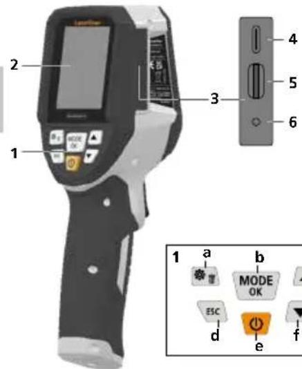
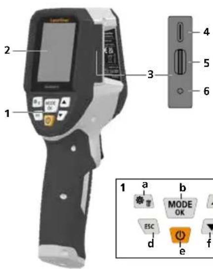
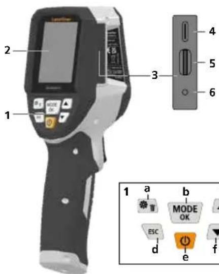
1 Hot keys
2 2,4" colour display
3 Connecting shaft
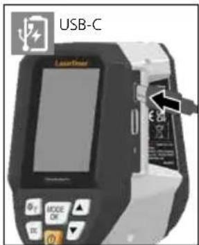
4 USB-C interface
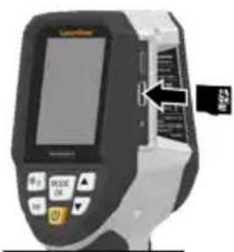
5 Micro-SD card slot
6 Charge status indicator
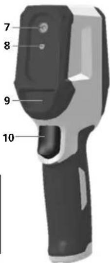
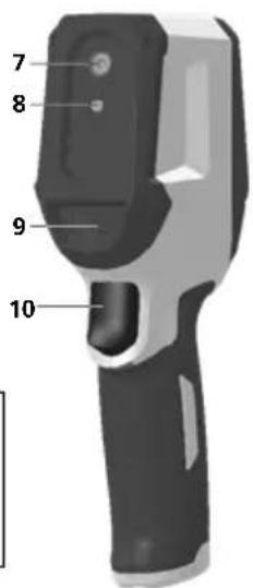
7 Infrared camera
8 Digital camera
9 Hygrometer
10 Trigger: save image
a Menu/Delete
b Change mode (IR-DP)/ Confirmation
c Menu navigation / overlay infrared / digital image
d cancel/back
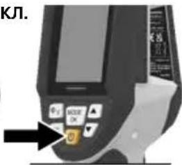
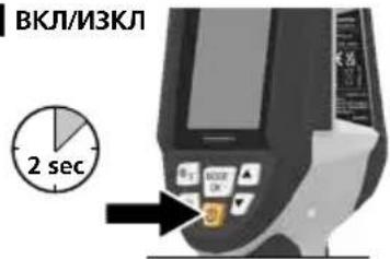
e ON/OFF
f Menu navigation / overlay infrared / digital image
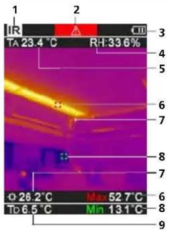
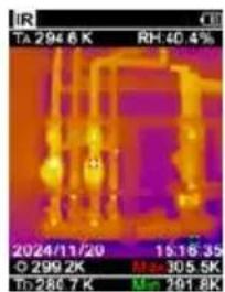
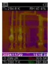
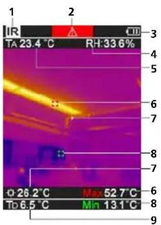
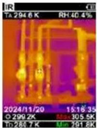
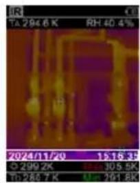
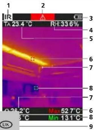
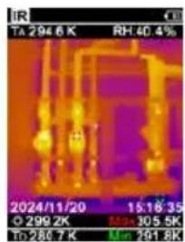
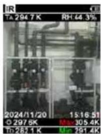
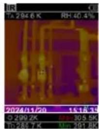
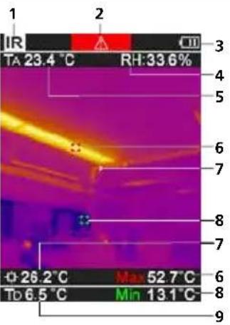
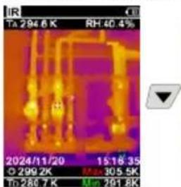
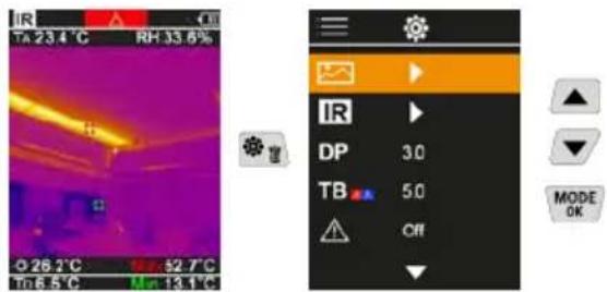
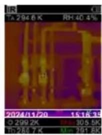
IR-Measuring view
1 Operating mode
2 Thermal bridge warning
3 Battery charge indicator
4 Relative humidity
5 Ambient temperature
6 Max. temperature
7 Temperature at centre of image
8 Min. temperature
9 Dew point temperature
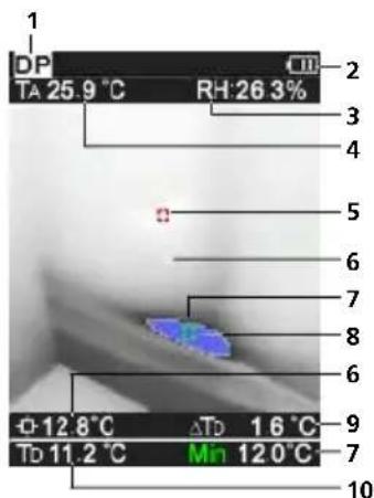
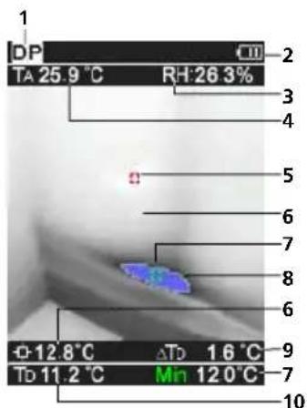
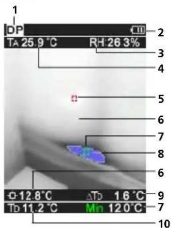
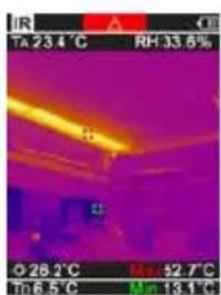
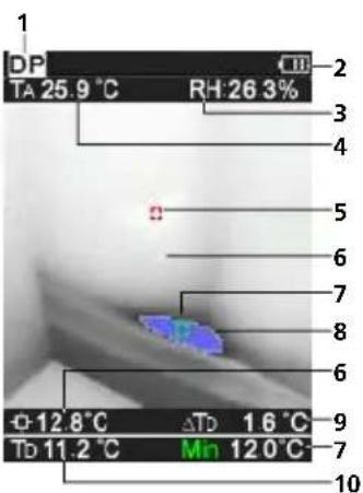
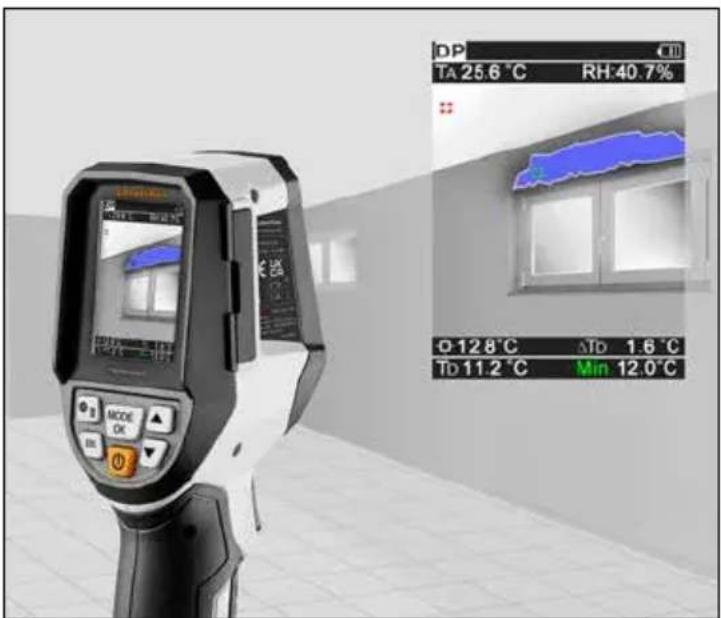
DP-Measuring view
1 Operating mode
2 Battery charge indicator
3 Relative humidity
4 Ambient temperature
5 Max. temperature
6 Temperature at centre of image
7 Min. temperature
8 Falling below dew point
9 Dew point temperature difference
10 Dew point temperature
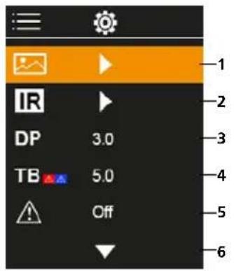
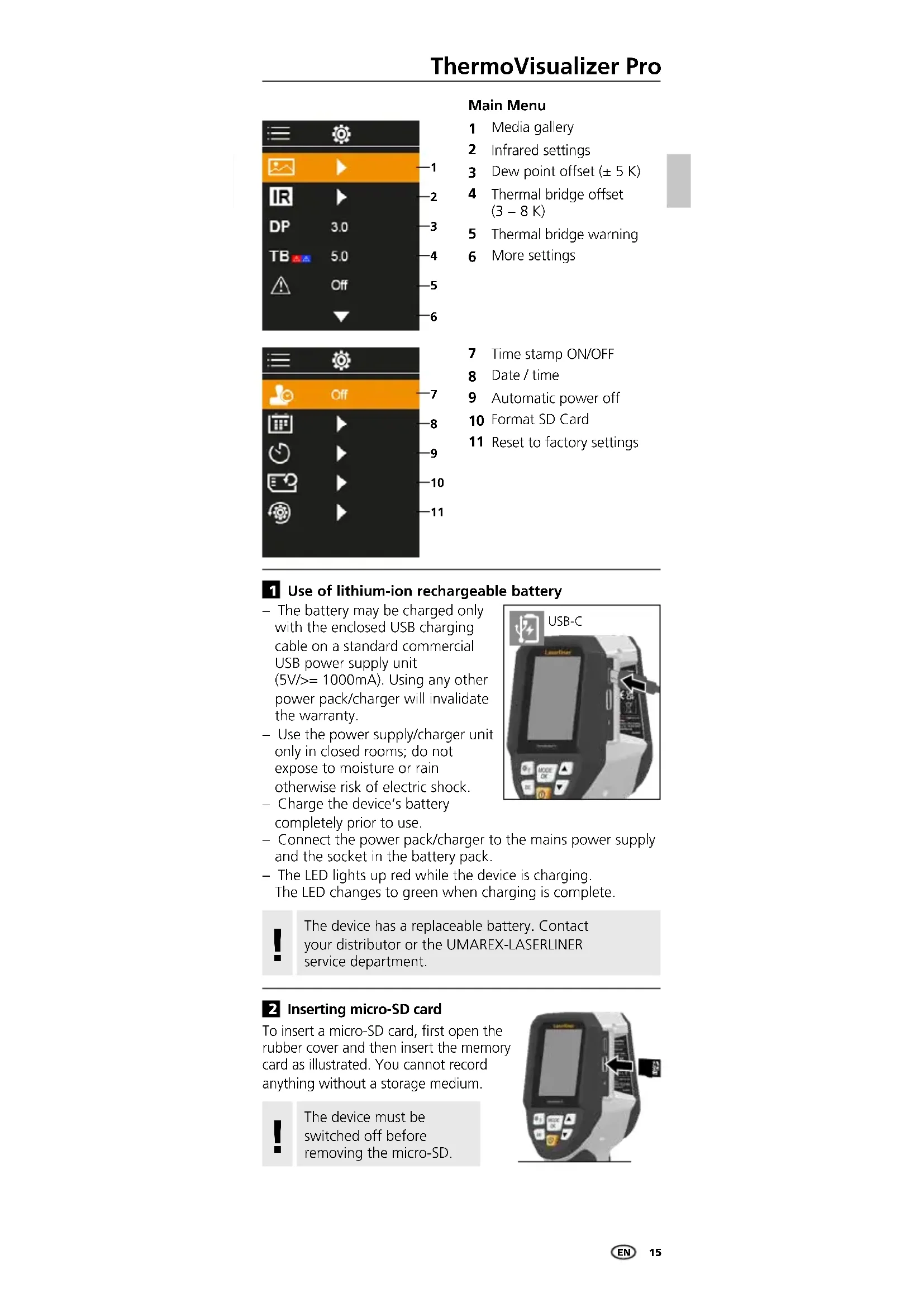
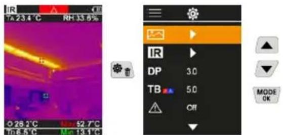
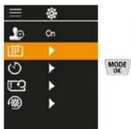
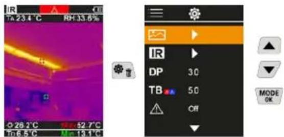
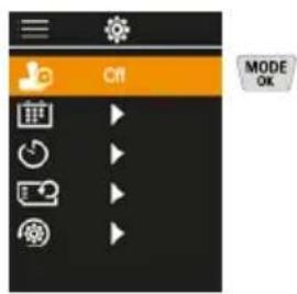
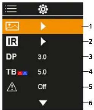
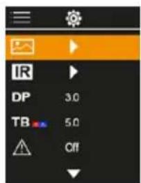
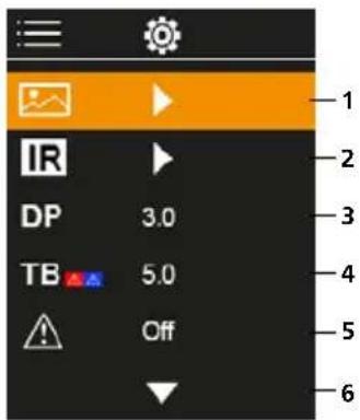
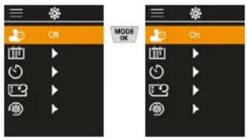
Main Menu
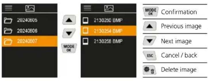
1 Media gallery
2 Infrared settings
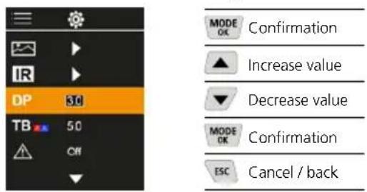
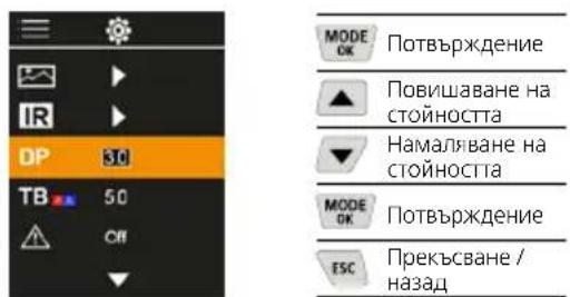
3 Dew point offset (± 5K)
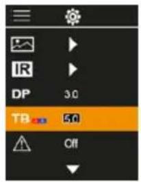
4 Thermal bridge offset (3 - 8K)
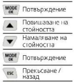
5 Thermal bridge warning
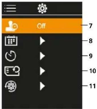
6 More settings

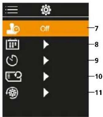
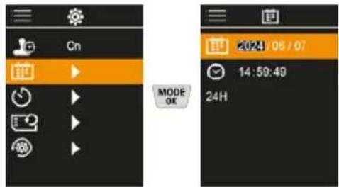
7 Time stamp ON/OFF
8 Date/time
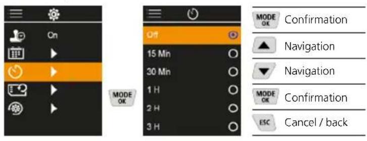
9 Automatic power off
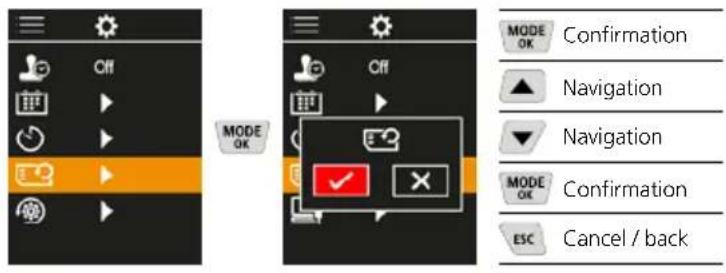
10 Format SD Card
11 Reset to factory settings
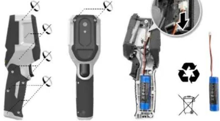
Use of lithium-ion rechargeable battery
The battery may be charged only with the enclosed USB charging cable on a standard commercial USB power supply unit (5V / > = 1000mA) .Using any other power pack/charger will invalidate the warranty.
- Use the power supply/charger unit only in closed rooms; do not expose to moisture or rain otherwise risk of electric shock.
- Charge the device's battery completely prior to use.
- Connect the power pack/charger to the mains power supply and the socket in the battery pack.
The LED lights up red while the device is charging. The LED changes to green when charging is complete.


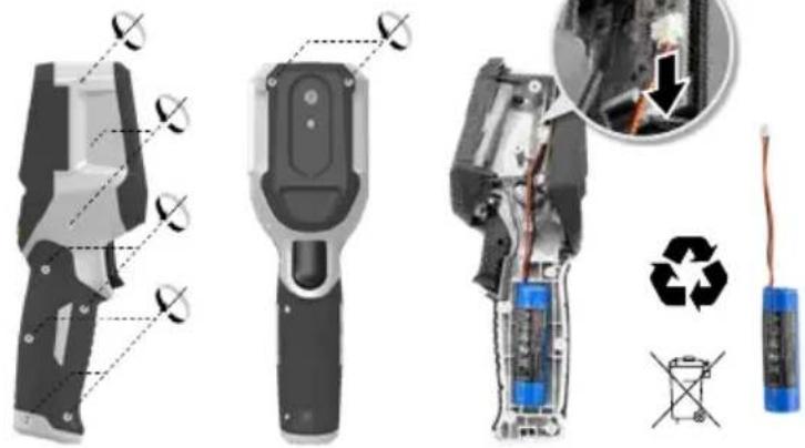
The device has a replaceable battery. Contact your distributor or the UMAREX-LASERLINER service department.
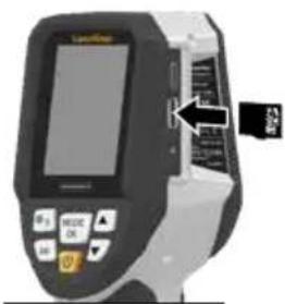
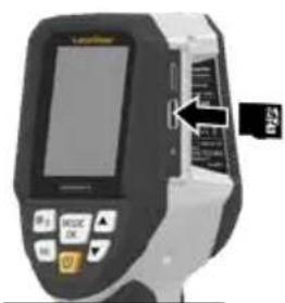
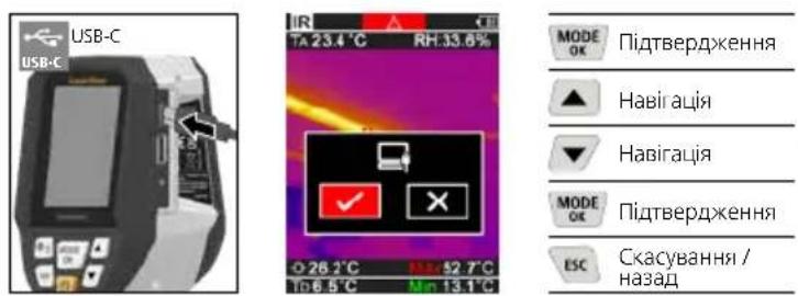
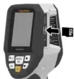
2 Inserting micro-SD card
To insert a micro-SD card, first open the rubber cover and then insert the memory card as illustrated. You cannot record anything without a storage medium.

The device must be switched off before removing the micro-SD.
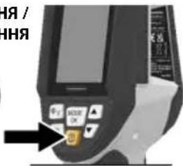
ON/OFF
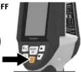
The product needs 20 minutes before use to acclimatise to the conditions at the place of use.
4 Infrared image (IR mode)
Depending on the colour palette used, the infrared image (thermal image) represents the surface temperature in colour. Temperature curves become visible and help with analysis of various applications, such as building inspection including detecting thermal bridges, working on electrical plants, machines heating and ventilation systems as well as locating heat sources or cold spots.
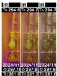
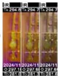
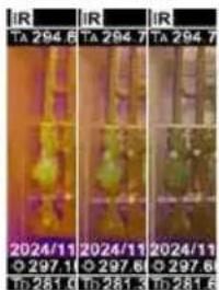
Image modes
There are 5 image modes to choose from.
A. IR image (Thermal image)
B. - D. Digital image with IR image overlay (MIX), 3 stages
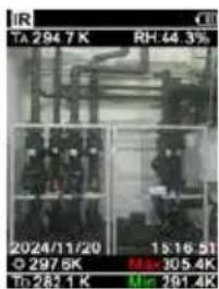
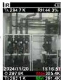
E Digital image (black/white)
A

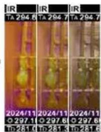
BCD

E
5 Dew point mode (DP mode)
The dew point mode is ideal for critical interior space inspections because it makes the areas where the dew point has been reached, or where the temperature has fallen below it, visible. The dew point mode is especially useful in buildings with high humidity or poor ventilation to enable preventive measures and better control of the room climate.
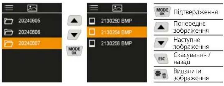
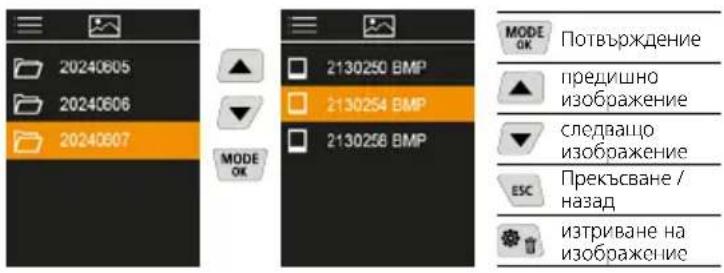
6 Image recording
Using the "Trigger" (10) button, users can take images of any measurement situation for the subsequent documentation. The images are stored in the media gallery in a folder named after the date in question.
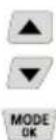
7 Main Menu
General and measurement-specific settings can be made in the main menu. The menu is controlled with the four hot keys.
7.1 Media gallery
All image data recorded with the ThermoVisualizer Pocket is available in the media gallery.
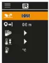
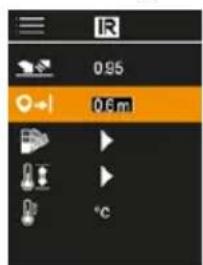
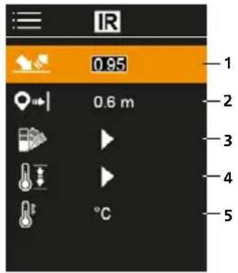
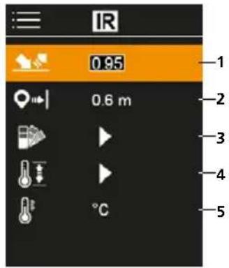
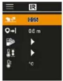
7.2 Infrared settings
Before each use, check the relevant parameters for infrared measurement or adjust them to the specific measuring situation to ensure accurate measurements.

1 Emissivity coefficient
2 Measuring distance
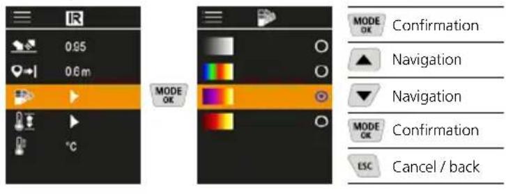
3 Colour palettes
4 Temperature range
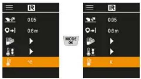
5 Unit ^ C / K
7.2.1 Emissivity coefficient
The level of infrared emissions given off by everything depends on the specific material and surface. This factor is determined by the emissivity coefficient (0.10 ... 1.0). For accurate measurements, it is absolutely essential that the emissivity coefficient is set first. The emissivity coefficient can either be custom set or selected from the predefined emissivity coefficients from the list.
Emission coefficient tables Reference values with tolerances
| Alloy A3003 Oxidised Roughened | 0.20 0.20 | Inconel Oxidised Electropolished | 0.83 0.15 |
| Aluminium Oxidised Polished | 0.30 0.05 | Iron Oxidised With rust | 0.75 0.60 |
| Brass Polished Oxidised | 0.30 0.50 | Iron, cast Non-oxidised Molten mass | 0.20 0.25 |
| Chromium oxide 0.81 | Iron, forged Matt | 0.90 | |
| Copper Oxidised Copperoxide | 0.72 0.78 | Lead Rough | 0.40 |
Metals
| Platinum Black | 0.90 | Steel Freshly rolled Rough, flat surface Rusty, red Sheet, nickel plated Sheet, rolled Stainless steel | 0.24 0.96 0.69 0.11 0.56 0.45 |
| Steel Cold rolled Ground plate Polished plate Alloy (8% nickel, 18% chromium) Galvanised Oxidised Heavily oxidised | 0.80 0.50 0.10 0.35 0.28 0.80 0.88 | Zinc Oxidised | 0.10 |
Nonmetals
| Asbestos 0.93 | Laminate | 0.90 | |
| Asphalt 0.95 | Lime | 0.35 | |
| Basalt 0.70 | Lime malm brick | 0.95 | |
| Brick, red 0.93 | Limestone | 0.98 | |
| Carborundum 0.90 | Marble Black, dull finish Greyish, polished | 0.94 0.93 | |
| Cement 0.95 | |||
| Ceramics 0.95 | Masonry 0.93 | ||
| China Brilliant white With glaze | 0.73 0.92 | Paint Black, matt Heat-resistant White | 0.97 0.92 0.90 |
| Clay 0.95 | Paper All colours | 0.96 | |
| Coal Non-oxidised | 0.85 | Plastic Translucent PE, P, PVC | 0.95 0.94 |
| Concrete, plaster, mortar | 0.93 | ||
| Cotton 0.77 | Quartz glass | 0.93 | |
| Earthenware, matt 0.93 | Rubber Hard Soft, grey | 0.94 0.89 | |
| Fabric 0.95 | Sand | 0.95 | |
| Glass 0.90 | Screed | 0.93 | |
| Glass wool 0.95 | Snow | 0.80 | |
| Graphite 0.75 | Soil | 0.94 | |
| Gravel 0.95 | Tar | 0.82 | |
| Grit | 0.95 | Tar paper 0.92 | |
| Gypsum | 0.88 | Transformer paint | 0.94 |
| Gypsum cardboard | 0.95 | Wallpaper, light-coloured | 0.89 |
| Heat sink Black, anodized | 0.98 | ||
| Human skin | 0.98 | Water | 0.93 |
| Ice Clear With heavy frost | 0.97 0.98 | Wood Untreated Beech, planed | 0.88 0.94 |
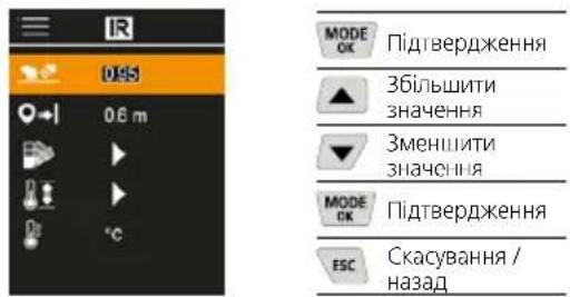
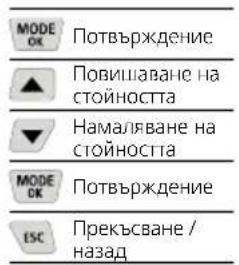
7.2.2 Measuring distance
The accuracy of the absolute measured values is influenced by the measuring distance setting. It should be matched to the relevant usage situation to ensure precise results.
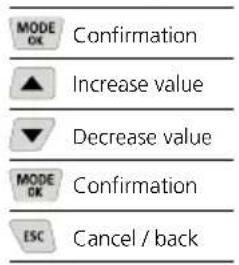
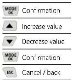
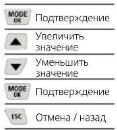
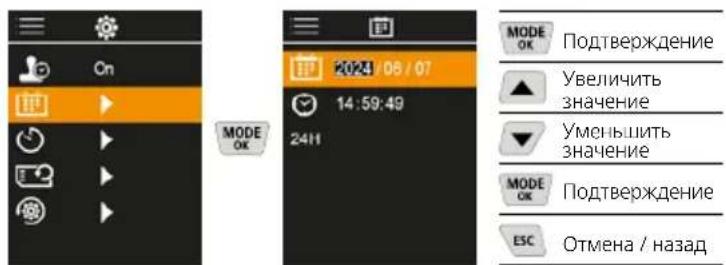
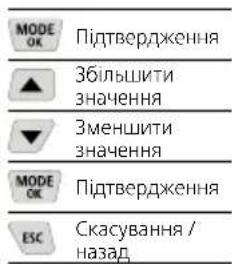
| MODE OK | Confirmation |
| ▲ | Increase value |
| ▼ | Decrease value |
| MODE OK | Confirmation |
| ESC | Cancel / back |
7.2.3 Color palettes
You can choose from several standard colour ranges to represent the measured infrared temperatures. Depending on the colour palette, the measured temperatures are adjusted within the current image section and displayed in the respective colour space.
7.2.4 Temperature range
This setting is used to adjust the temperature range of the IR image and the resulting distribution of the colour spectrum of the infrared image.
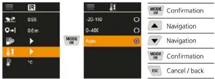
In automatic mode, the temperature range is automatically adjusted to the highest measured temperature. The switching process can take several seconds; "Image Calibrating ..." appears.
7.2.5 Temperature unit
7.3 Dew point offset
The dew point offset of -5K to +5K enables fine adjustment of the threshold at which the critical areas are displayed. Areas whose surface temperature is below the dew point temperature ± offset are marked in blue in the image.
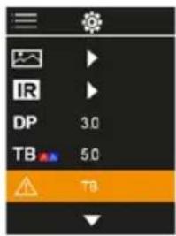
7.4 Thermal bridge offset
The thermal bridge offset is an adjustable tolerance of 3K to 8K that specifies the temperature difference between the surface mid-temperature and ambient temperature, above which the camera recognises and highlights a thermal bridge warning.
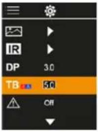


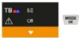
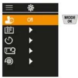
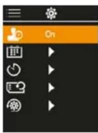
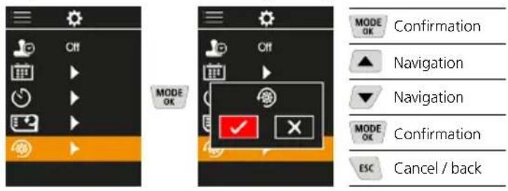
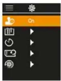
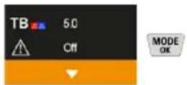
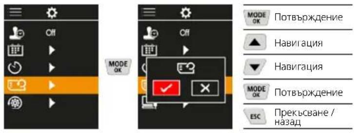
7.5 Thermal bridge warning
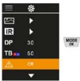
Temperature at centre of image + offset lower than ambient temperature

Temperature at centre of image + offset higher than ambient temperature

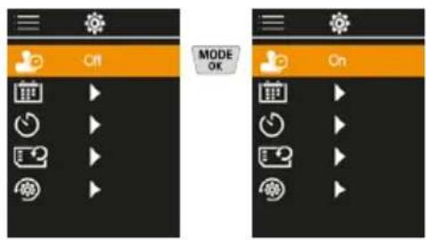
7.6 More settings
7.7 Time stamp
Select from here whether to include date/time information in the photo.
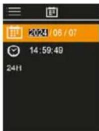
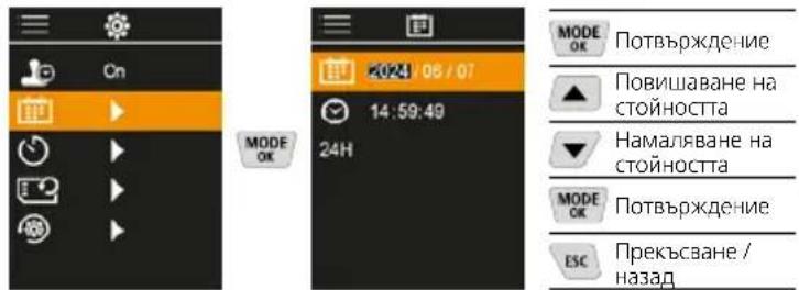
7.8 Date / time
The time and the date can be set with the cursor keys and the time format changed from 24 h to 12 h.
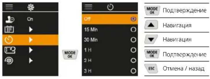
7.9 Auto power off
The device switches off automatically after a set period of inactivity.
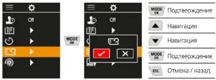
7.10 Format SD Card
All data on the SD card will be deleted. This procedure cannot be undone.
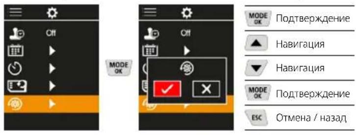
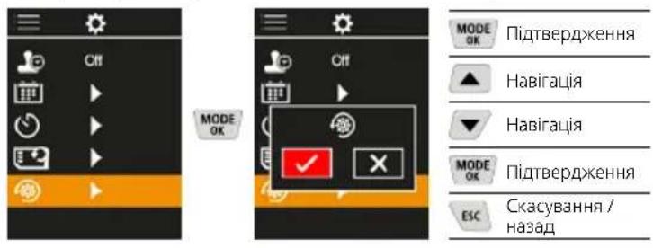
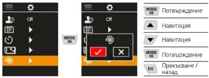
7.11 Reset to factory settings
All parameters are reset to factory setting
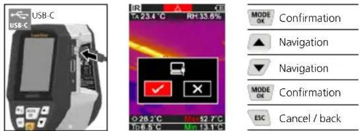
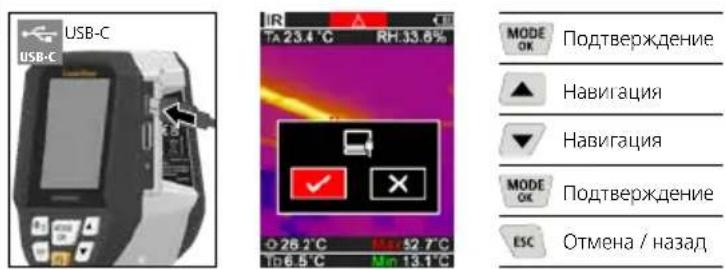
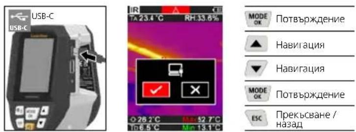
8 Data transfer
Data saved on the micro-SD card can be transferred to PC either with a suitable card reader or via the USB-C port.
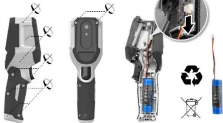
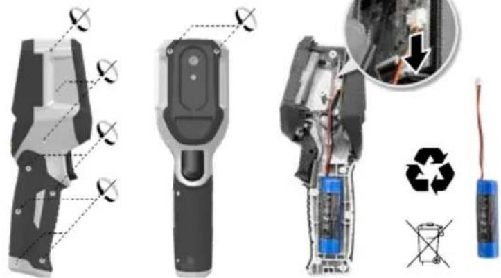
9 Removal of the battery
Information on maintenance and care
Clean all components with a damp cloth and do not use cleaning agents, scouring agents and solvents. Store the device in a clean and dry place.
Calibration
The measuring device must be calibrated and tested on a regular basis to ensure it is accurate and working properly.
We recommend carrying out calibration once a year.
Contact your distributor or the UMAREX-LASERLINER
service department.
Technical data (Subject to technical changes without notice. Rev25W01)
| Measured variable | Infrared temperature, Relative humidity, Ambient temperature, Dew point temperature |
| Mode | Digital image, infrared image, dew point, MIX image |
| Functions | Thermal bridge warning, image recording, real-time clock, MIN/MAX, dew point, USB mass storage |
| Focus fixed-focus | |
| Spectral range 8-14 μm | |
| Therm. sensitivity (NETD) 60 | mK @25°C |
| Measuring range infrared temperature | -20°C ... 150°C, 0°C ... 400°C |
| Accuracy infrared temperature | ± 2°C (0°C ... 40°C), 4°C or 3% (<=0°C, >40°C) |
| Resolution IR sensor 96 x 96 | pixels |
| Infrared temperature resolution | 0.1°C |
| Sensor type uncooled micro | bolometer |
| Field of view (FOV) 50° | |
| Spatial resolution (IFOV) 9 mrad | mrad |
| Image frequency 9 Hz | |
| Minimum focus distance 0.3 m | m |
| Digital camera resolution 320 x 240 pixels | |
| Screen type 2,4" Colour TFT | |
| Display resolution 320 x 240 | pixels |
| Image format BMP | |
| Technical data (Subject to technical changes without notice. Rev25W01) | |
| Emissivity coefficient adjustable, 0.01 ... 1.00 | |
| Measuring range ambient / dew point temperature | -20°C ... 60°C |
| Accuracy ambient / dew point temperature | <+/- 1°C 0 ... 60°C) <+/-2°C(<0°C) |
| Measuring range Humidity 0 | ... 100% rH |
| Accuracy Humidity | +/-2% (20% ... 80% rH) +/-3% (<20% & >80%) |
| Memory | Micro-SD memory card up to 32 GB |
| Protection class IP 54 | |
| Connections | 1/4" tripod thread USB type C |
| Auto power off adjustable | |
| Power supply | Li-ion battery pack 3,6V / 2,55Ah |
| Operating time approx. 4 hours | |
| Charging time approx. 2.5 hours | |
| Operating conditions | 0°C ... 50°C, max. humidity 85% rH, no condensation, max. working altitude 2000 m above sea level |
| Storage conditions | -10°C ... 60°C, max. humidity 85% rH, no condensation |
| Dimensions (W x H x D) 69 mm x 220 mm x 77 mm | |
| Weight 275 g (incl. battery) | |
EU and UK directives and disposal
This device complies with all necessary standards for the free movement of goods within the EU and the UK.
This product, including accessories and packaging, is an electrical appliance that must be recycled in an environmentally appropriate manner in accordance with European and UK directives on waste electrical and electronic equipment, batteries and packaging, in order to recover valuable raw materials. Electrical devices, batteries and packaging do not belong in household waste. Users are obliged by law to surrender used batteries or battery packs to a public collection point, to sales outlets, or to technical customer services, free of charge. Remove the battery pack from the device without damaging it using standard tools and a separate collection arranged before returning the device for disposal. Please do not hesitate to contact the UMAREX-LASERLINER service department if you have any queries regarding removing the battery. Look for information on local disposal facilities and note the relevant disposal and safety information at the collection points.
Further safety and supplementary notices at: https://packd.li/ll/apb/in
Laserliner
1
https://packd.li/ll/apb/in
Laserliner
1. 实验原理
7.2.3 Gamas de-colored
https://packd.li/ll/apb/in
Laserliner
m = 311
https://packd.li/ll/apb/in
!
https://packd.li/ll/apb/in
!
https://packd.li/ll/apb/in
Laserliner
#
https://packd.li/ll/apb/in
Laserliner
1
IIOHocTbIO npOHTte IHCTpyKUIO NO 3KcNpyTAuIN,
PpInaeraMBI npOCNEKT ,HOpMaunr O rapAHIN
nDOnoHNHTeBHBIE CBeDEHNA, a TAKKe NocJeIHIO
IHOpMaUIO u yKa3AHN, KOtOpBie MOxHO HaITn IO CbIKke
Ha cAIT, nPiVeDEHHOB KOKHe 3ToN IHCTpyKUIN. Co6JIIOaTB
CoDEPKaUncEBA TIXN DOKymeHTax yKa3AHN. DaHHbIE
DOkymeNTb CNeyET COxpaHNTB IN B CnyAae NpepaHn IN3dENNA
PepeDaTb HOBOMy NONb3OBaTeJIIO.
McnoJb30BaHne no Ha3HaueHnIO
HactoJee H3dJIeNne IpeHa3HaYeHO JINBn3yAIn3aunn DnHaMnKn 13MeHeHnra TemnepaTpybl, MoCTNKOB XOLOda N MeCT BbIaNDeHnRA KOHeHcata. OHO n3MePReT TemnepaTpy pno INHpaKaPacHomy 13NyHeHIO, OTHOCHTeMbHyBOaXHOCTb BO3dyxa, TemnpaTpy OKpykaHooi e Cpebl nTOky poCbl.
06uye yka3aHH no TexHKe 6e3oNaCHocTn
- Pn60p nCnoB3OBaTB ToIbKO CTOPO NO HA3HaueHIO N B npedeJax yCNOBm, YkA3aHHbIX B CneuΦnKaun.
- I3mepuTeIbHbIe npu6Opbl n npHaIeXHOCTN K Hm - He ngpyuKa.
IX cIeNyET XpaHHTB HeIOCTynHom dIa DeTeMcTe.
BnOCTb B npI6Op IIO6Be I3MeHEnr IIN MoNΦKauu 3aIpeueHo, B npOTNBOM Cnyae DOnyck N Tpe6oBaHn NO TEXHKe 6eONaCHOt yTpaNVBAOT CBOO cnly. - He noDBepraTb npi6op MexaHnueckm Harpy3kam, Ype3MepHBIM TempepaTypam, BnaxKHOCTN ININ CInuHKOM CNJbHBIM Bu6paunr.
- 3anpeaetcpa6oTaB c npnbopom B cnyae otka3a odHOnnnn HeckoIbKnx yHKun, pnp Hn3kOM ypOBHe 3apra 6atapen, a TAKKe B cnyae NOBpeJDeHnKOPnyca.
- Pn3KcNpyataunBne nomeeHn CneiHTb 3a Tem, TTo6bl npu6op NCIOJIb3OBAJICA TOJIbKO Pn COOTBECTBYUONx aTMOCfephbx YCNOBnIX N CO6JIIODeHnEM NOXODAUX Mep 3aUNTBI.
IpaBnla TexHKn6e3ONaCHoCTN
ObaaueHnC 3neKtpomarHHTbIM n3nyeHnEM
-Bn3MepuTeNbHOM npnbOpoe Co6HHeHbI HOpMbI nnpedeHbHbe 3NaueHn, yCTaHOBLeHHBe IpImeHHTeHbHO K 3NeKTpOMarHHTOH COBmecTmOCTn COrnaCHO dIpKeTnBE O 3NeKTpOMarHHTHa COBmecTmOCTb (EMC) 2014/30/EU.
CneNyETco6nOaTbDeIeCTBvIOuNBE KOHKpeTHbIX MecTx ORpaHnueHnnoKcNllyaTaunn,HaNPmep,3anPeT Ha IcNoJIb3OBAHnE B BoJbHNuXax,B CaMOJeTAX,Ha ABTO3aPABkAx ININ PAnOM C JIODbMn C KApDIOCTMUYIaTOpAMn. B TAKNX YCNOBnX CyUeCTByET BO3MOxHOCTb ONaCHOFO BO3NeICTBnR IBO3HKnHOBeHHN NOMEXOT IN DnaJIeKTPOHHbIX PnIbOPOP8.
3KcIpyataaHIOBbOKHM HApJKeHEm NIN B YCIOBnX DeCTBn MOuHBx 3JeKTPoMaHrHTbIX NepeMeHHbIX NOJIe MoKet IOBJIraTb Ha TOOHCTb N3MepeHn.

1 KhoNknpamoro dienCTBn
2 UBeTHOH TOHKONJIeHOHHbI nucnneHa 2,4"
3 PeBnHOHHbKOIOeCu
4 Cnotnla USB-C
5 THe3DoIyycTaHOBKn MmKpOKapTbSD
6 INHINKauNcoCTOHN 3apn
7 HppaKpaHaa Kamepa
8 LndppoBaKaMepa
9 TnpomTp
10 Trigger: coxpaHnTB nO6paKeHne
a McHIO/ydaIINb
b PepeKIOUHTb peKIM (IR-DP)/ POnTBCpXJcHc
KhONKa HABnraU No MeHIO /nepeXoHa HnOpaKpaChoc nn Ha uDpOboe
OTMeha/Ha3a
BKJI./BbIKJ.
f KHONKa HABINaIIN NO MeHIO /nepeXoN Ha INΦpaKpaCHOe NNHa cnpoBoe
IR-BuB BpeKIme N3MepeHn
1 Pekimpa60tbi
2 PpeynpeckdHne o MoCTnKe XoIOna
3 Hndkaunzaepa#a6atapen
4 OTHOCHTeBHaB BnAaXHOCTb BO3dyxa
5 Temnepatypa okpykaioe cnpebl
6 MaKcImaJIbHaI TemnepaTpa
7 TemnepaTypa,ueHtp 306paXchHn
8 MmHMaJIbHaI TemnepaTpa
9 Touka pocbi
DP-BuB BpeKIme n3MepeHn
1 Pekimpa60tbi
2 Hndkaun3apda6atapen
3 OTHOCHTenbHaB BnaxHOCTb BO3Nyxa
4 TemnepaIpyoKpykaIOUe npde
5 MakcmaJIbHaTtemncpaTypa
6 TemnepaTypa,ueHtp 306paXeHn
7 MHHMaJIbHaI TemnepaTpa
8 TemnepaTpa Hnke ToKp ocbi
9 Pa3HOCTb TOeK pOcBi
10 Touka pocbi


TnaBHOe MeHIO
1 Tanepea-06bekTOB
2 HactpoKn, nI INHpaKaPaChoro 3JIyHeHHa
3 CmeueHne ToQn poCbl (±5K)
4 CmeueHne MOCTIKOB XOJODa (3-8K)
5 PpeynpeKdEHeNo oMOCTnke XoIOnDa
6Дугне NaCtpoKn
7 BkIOueHne/BbIKIOueHne MeTKn BpeMeHN
8 Data/BpeM
9 ABTomatnuheckoBbIKJIOHnI
10ΦopMaTnpoBaHne SD-kaTpbl
11 BocctaHOBHeHne 3aBOIDCKNX HAcTpoE
1 06paueHHe c JIHTn-IOHHbIM aKKyMylATOpOM
-ДяЗapдк pa3peшаetcN CNOJb3OBaTb TOnbKO BXOJaU N B KOMJIeK T NOCTaBKN 3apJHbI Ka6JIb USB co CTaHApTHbIM 6JOKOM NtAHn USB (5B/>=1000MA).Pn INCNoJb3OBaHn HeOpuHaHbHO 6JOKa NtAHn/3apJHOro yCTpoICTBa rapaHTnaHHyInpyETcR.
-5JOK NITAHN/3aprADHoe yCTpoiCTBO NCNOJIb3OBaTb TOnIbKO BHyTpI 3AMKHYtbIX NOMEueHEN, He IIOBepraTb BO3JeNCTBnIO BnaI INI IOXJ4, T.K. B NPOTNBOM Cnyae CyueCTByET ONACHOCTb NOPaxEHIN 3JNEKTPNueCKM
IpeNcNoB3OBAHnEM npi6opa Heo6xoDIMO noJHoCTbTO 3apdntb aKKyMyJIaTOp.
IOncoeHnHTb 6NOK nITaHn/3apAIDoe yCTpoCTBO K 3JeKtpocetu pa3bemy, KOtOpBn HaxoDntCBAOTDeJIeHN DIAKKyMyJTAToPA.
-BoBpem3apnnpbopa CBeToIOO TropNT KpaChbIM CBeTOM. EcnCBeToIOO TropNT 3eJIeHbIM CBeTOM,3HaHT npoecc 3apKn 3aBepweH.

Pp6op nntaetc0 tmeHHoro akkyMnToppa. B 3om cnyae Bam Heo6xOIMO CBra3aTbc8 C aBtOpu3OBaHbIM dIJIepOM nnC epbncbM OTeJenOM UMAREX-LASERLINER.
BcraBntb MMkpoKapTy SD
Ду yctahOBK MmKpokapTb SD chayana OTKpbTb pe3INHOByIO 3aJlyuKy, a 3aTeM BCTABNTb KapTy NAMATN B COOTBETCTBUN C pncyHKOM. 3aNNCb daHHbIX 6e3 Hocntenr HEBO3MOxHa.

Ipeepn3BneHennemKapTbI naMrtn MicroSD cJeayet BbIKJIOuHTb yCTpOINCTBO.
3 BKJI./BblKJI.

Ipeep nCnoB3oBaHnEM
n3dJIne Heo6xOJIMO
OCTaBtB Ha 20 MNHyT B
MeTe nCNoB3oBaHnA JnA
aDaNTaUIN KycIOBnAM
OKpyXaHOUsE Cpebl.
4 Hnppaekpachoe n3o6paKeHne (peKIM IR)
Ha INHpaKpacHom N3O6paXeHN (TeNIOBOM N3O6paXeHN) UBETOM B COOTBeCTBm C HAcTpoIkAMn OTO6paXaETCpaCnpedeJIeHne TEMpeApTy npOBepxHOCTn. Bu3yaJIN3aUNn DnHaMnKn N3MeHENA TEMepaTypbI NCNOJB3yETcB CaMbIX pa3HbIX 06laCTAX I NOMoAet npn aHaJIIn3e, HAnpIMep, PnO OCMOTpe 3daHn, BKJIQUaHOUeM BbIABJIeHne MOCTIKOB XoJOnDa, BbINONHeHn pa5OT Ha 3NEKTPOO6OpyDOBaHn, CTaHKax, OTONITeNBbIX IN BEHTNJUcIOHHbIX CNCTEMax, a TAKKe npn IOKaJIIN3aUNN ICTOCHNKOB TENJa IN XOJOIDhix 3OH.
Pexkmbi n3o6paekhen
IpeDyCMOTpeHo 5 pa3HbIX peKIMa n3O6paKeHnA.
A.Инфрахрахhoeизбрахене(Tenлобoeизбрахенe)
B.-D.LiΦpOBOe 306paXeHne C nepexoJOM Ha NK
n3o6paKeHne (MIX), 3ypoBn
E.Lufopooe n3o6paXeHne (uehny/6eIb)


A E B C D
5 PeKMM TOOK pocbl (peKMM DP)
PeknTOckPOcbIeAebHO NOxOoNT INa KOHTpOJIbHOrO OcMOTpa nOMueChN, TAK KAc OH N03BOJrEeOBHApYKntb 30Hb, TEmpeatypa B KOTopbX paBa HIN HNKe TOckPOcbI. PeknTOckPOcbIOOC6ehno NoJe3EN pRi HNCNEKUHN 3dAHN C BblCOKO BNAHXOCTBIO BO3dyxa UIN HeIOCTaTOOH BeHTNJLlUeNe, TaK KaOH NOMORAET PInHHMaTb peuHHeN O npOuNakTmecnx Mepax IN CnOCo6CTByet yLyUHeHIO KOHTPOJIHaND MKNPOKlIMATOM B NOMEueHnx.
6ΦOTOCbEMKa
YTo6bI CTeNaTb CHMOK nIgNo3nHeHJero npOTokOIpOBaHN, npu IIO6oM N3MepeHIn IOCTaTOUHO HaxaTb KHOKy ,Iyck" (10). N3O6paXeHn COxpaHnIOTcB rAJIepee N3O6paXeHn B nAnke, Ha3BaHHo IIO COOTBeTCTByIOUeN dATE.
7 TnaBHO MeHIO
Yepe3IaBHOe MeHIO MoXHO 3aDaBaTb KaK O6UHe HAcTpOKn, TaK IN HAcTpOKn, OTHOCaUneC K N3MepeHnM. YnpabTb DeNCTBnMn B MeHIO MOXHO C NOMOuBHO YeTbIpex CyHKUoHaJIbHbIX KHONOK.
7.1 TαJIepea-Meda-ObbeKToB
Braapee H3o6paXeHm MOxHO Bb3bBaTb BCE noIyehHbE C nOmoUbio ThermoVisualizer Pro H3o6paXeHn.

7.2 HacpoKn nHΦpaKpaChoro n3nyeHna
YTo6bI rapaHTnpoBaTb npaBnJbHocTb N3MepeHni, npei KaKdbIM NCNoJIb3OBAHmE CNeJyET npOBepNTb napAeTpbl INHpaKpaChbIX N3MepeHNI ppi HeoXoDnMOCTN CKoppeKTnpoBaTb nx C yyeTOM IMeIOxNXcYcNOBNI.
1 Ko30nHHTN3nyHeHH
2 PaCToHHe N3MepenHn
3 NaHTpbUcBeTOB
4 TempepatpHbI dHaana3OH
5 EINHua n3MepeHHa ^ C / K
7.2.1 KoΦΦnueHT n3nyeHn
HHTeHCNBHO IHpapacpachoro n3nyehnra,NCyckaemoro IIObIM TELOMBaBcIMOCNTO MATEPnAJa / NOBepxHOCTo,ONCbIBaETc KO300NEHTOM n3nyehnra (0,01 ... 1,0).Ipy npabNtBOHO n3MepeHHRAOB3aTeJbHO Heo6XoDIMO HAcTpaBaT Ko300FNIUEHT N3Jyehnra. HAp4y C 3aDaAHbIMN KO300FNIUEHTAMn n3Jyehnra n3 CNCKa BO3MOKHa HAcTPOKa INDINBnUdYAbHBIX KO300FNIUEHTOB N3Jyehnra.

Ta6nucbKOeΦmneHTOB3nyeHna
3Jecb MOXHO Bb6paTb, 6yDet nn yKa3bBaTbCn Ha n3o6paKeHNx METKa BpeMeHn.
7.3 DaTa /BpeM
Bpemn DaTy MoXHO HAcTPONTb KHONKaMn CO CTepeNkAmn, KaK B 12-ycaOBOM, TAK N B 24-ycaOBOM fOpMaTe.
7.9 ABTomatueckoro BbIKIOueHn
IIO nCTeueHn 3aHaHHoro nepnoo 6e3JeCTBn npnbop ABToMaTnueCKN BbIKJIOuHTCra.
7.10 DopMaTnPoBaHne SD-KapTbI
Bce daHHhe Ha KapTe namTn SD 6ydyr ydaIeHbI. OTMeHHT b 3Ty onepaIIO noCne ee BblnoJIHCHMa Yke HcIb3I.
7.11 BocctaHOBJIeHne 3aBOcknX HAcTpoEK
BCEXIpaMeTPOB BOCCTaHaBbAIOCTaBOcKne HaCTpOKn.
8 Peredea daHbix
CoxpaHCHIIbIe Ha KapTe NaMAtn MicroSD dAHIIbc MoXKnO IINo CHTaTb C nMOUHIO NOxOJaIero ChITbIAIOIero yCTpOcTBa, INo nepeNaTb Ha Nk uee3 nHTepEic USB-C.
9 N3BneueHne aKKymyIaTopa
Hhopmaqna no o6cnykBaHnO yxoNy
Bce KOMNoHEnTbOuNtAaTb CnErKa BnaJxHo nCaIpeTKo; He IcNoIb30BaTaYnCTaUe CpeICTBa, a6pa3nBhIbe MaTePnAJIbI n pactBopnteI. Pnp6Op xpaHnTb B NCTOM n CyXOM MeCTe.
Kajinbopkka
IJa o6ecneHnToHocn pe3yIbTaTob n3MepeHn I yHKUHOHaJIbHOCTn CIEnyeT peYIpaHNo IPOBOuNTb KaIbPbOky npOBepKy n3MepntelbHoro npBopa. Mbl peKOMeHyem npBOOnTb KaINbPbOky c nepIOduHOCbIO pa3 B rOd. Bbl moKeTe noLyHTb KOHCyIbTaUIO NO 3OTMy BONpOcy y BaWero npDaBua nn COtpydnKOB CNxkbI noDpejKKn UMARE-LASERLINER.
IpeqncaHnE C n BenKo6pTaHn n yTuIn3aun
PnpbOp COOTBeTCTByeT BcEM HeoXOJIMMbIM Tpe6oBaHnAM, perIaMeHTpUoiue CBO6oHbI TOBapoo6opOT Ha TeppntOpN EC n BeNIko6pTuHaHH.
JaHHoe n3JeHne, BkIOUaY KOMJIeKTyIOuIe npHaJIOeKHO tynakOBky, ABnEraTcAeKTPnueCKM yCTpoCTBOM, KOtOpoe corlaCHO napeKTHBAM EC n BeINKO6pHTAHN O CTapbIX 3eKTPnueCKNX n 3eKTPoHHbIX yCTpoCTBxA, 3JeMeHTAX NITAHN, AKyMyJrTOpax uynakOBOuHHx MaTePnAAx DOJXHO bItb NepeDaHO h AytINIm3aUIO 3KoONURHeCKN 6e3OnaCHbIM CNOOCoBm C cEnbIO NOyHeHnueHnCeHHORc Ibpb. 3eKTPnueCKNe npbOpbl, BaTapeKn y naKOBKa He oTHocTc K 6bToBbIM OTXdAm. IOTpc6nteNl No 3aKOHy Oba3aHb 6ecnIaTHo CdaBaTb NCNoJIb3OBAHbHe B TaapeKn N aKKyMylrTOpbl B CNEuaJIIM3npoBAHbHle O6IeCTBeHNbIe NyHKtBcOpa OTxODB, JIoBO NO MeCTY PPODAKN IN B CIny6By TexHHeCKOn NODepkKn. N3BLeKNTe AkymyIATOP C NOMOsbIO O6bHyBx INCtpyMeTOb, Hpe3py7Aero, N CdAIte B OTDeJIbHbN pyHKTcOpa, IpexKe qem OTPiABIne pnpOp Ha YtINIm3aUIO. N BoCEM Bonpocam O6 N3BLeChENi Batapeek O6paauIteCB B cepBcHbN OTDen UMLAREX-LASERLINER. INfOpMaUNIO O NYHKtax C6opa NytINIm3aUIN OTXODMOXHO NOJyHTB B ADMMHnCTpaUNIO MceTy XtKeJIbCTBa. Co6IIOaJIte INHCTpyKUnN IO YtINIm3aUNI IN PpaBnla TExHKn 6e3OnaCHOCTN B NyHKtax pniema O TxOIOB.
Дугге npавILA texнки 6e3oNaChOCTn n ДОпОнHTeЛьНБIe
ИнстPyKcUIM CM. NO aDpeCy:
https://packd.li/ll/apb/in
!
Ybaxho npoHTaTe iHCTpyKciO 3 ekCnnyataTt Ta 6poWypy IHopmaia npraHantT Ta daTkoBI BIDOMOcTI, Jka DoaCTbC, Ta O3HaNoMTecB 3 aKtyaIbHMn DaHmN Ta peKomeHdaizmiMa 3a NocuHaHHM B KInci ciEi iHCTpyKci. DToPmMyTEcb HactAOB, 00 B HNX MCTaTbc. CiDOKymEnTn CIId 36peRT Ta nepeaTn pa3OM 3 BnpoBom HaCTynHomy KopncTyBaueBi.
BukopncTahnHa 3a npn3haeHHaM
LcBnBp6 npn3HaHeHm IaI B3yA13aui 3MIn TEMpepaTy, TERIOBHX MOCTIB Ta KOHNecHcy. BiNb3Haue TemepaTpy IHppaepBOHO BRIPOMIHIOBAHH, BiHOCHy BOJorictb, TemepaTpy HABKOJIINHbORO CEpeoOBuHa Ta TEMpepaTy TOKn pOcN.
3aRaIbHI Bka3iBKn no 6e3neci
BnKOpNCToByIe npJnaD BnKlnOuHO 3a npn3HaueHHaMn B MEXKaX 3aABJIeHNx TEXHHiHNx XapaKTepNCTNK.
BumipioBaJIbHI npnIaI npnIaIJaIO Hx He nTpaIgpaUKa. 36epiratyn HeNoCoxHOMy dIraIteRmicui.
- Ipepeo6Kn Ta 3MiH NOKcTpyKuII npuNaIy He Do3BOJIAOTbC, IHAKUe AHJIOHTBCr DOnyCK Do EKcNlyatauTa CBIOuTBO npo Be3neuHiCTb.
- He hapaxaIte npnlaH aMexaHicHe HabaHTaXeHHa, ekCTpeMaJIbHy Temnepatypy, BONorict b 60 cunbHi Bi6paui.
3abopohraetbcraekcnnyataa npnana y paay biIMMOBn Ondiei KInbKoxyHKui a6o npn Hn3bkOMy pIBHi 3apAkyAkyMylTopa, a TAKOX NOKOKeHHI Kopnycy.
BnKOpNCBOyUHn npnlaI npocTo He6a,3BaKaIte Ha HaaBHicTB BiIOBIHNX nOuHNx yMOB a6o BxNBaIte HaneKHX 3an06ixHX 3axoIDIB.
Bka3iBkn 3 TexHikn 6e3neKn
NoBdoKehn3 3KepeIamn eJekTpomarHITHO BInpPOMIHOBaHH
Bumipobaln npnaad Biinobiae Bmorma i o6mehenm zo do eNekpomarHtHOi cymicho3riHNO npekTNBn EC 2014/30/EU,ka niDnanae nii dio napeKTNBn EC npo paiooabnaHaHHa 2014/53/EU.
- Heo6xioHO DToPmByBaTnCJIOKaIbHnx EKcnIyatauiHnx OMeKeHb, HapnPKaIad, B IiakpHax, JITakax, Ha 3anpaBHX CTahuix a60 npuy 3 IIOdbMn 3 eNEKtpOKApDIOCTMMyIATOpOM. lChye MOXJIuBiCt b HeraTINBHorO BnIbBy a60 npuyeHHra p60Tu eNEKtpOHnx npicTpoiB / cpe3 cEKeKtpOHHi npicTpoi.
- PnBnKOpncTahH B 6e3nocepEHHI 6bn3bKocTi BiJ liHi BnCOKoi Hanyr n a6o eJeKtpomarHITHX 3MiHHNX NOiB pe3yJIbTaTN BmipHOBaHb MoKyTB 6TyH HeTOOHMM.

1 KOMaHnHi KHONKn
2 Kolbopobu 2,4- IOIMOBN TFT-dncnne
3 Po3'emIJIPIKIOUeHHH
4 USB-C-nopT
5 Cnot dIa Kaptn Micro-SD
6 INHINKauNcoCTOHN 3apn
7 HphppaKpaHaa Kamepa
8 LncpObaKaMepa
9 Tnpometp
10 Trigger: 3nomka
a MeHIO/ydaJIuTb
b PepeKIOuHTb peKIM (IR-DP)/PiTBePdKeHHa
C HabirauiHe MeHIO/3MiHHTU UΦPOBE 3O6paXeHHa nepexiHa iHpaepBoHe
d CkacyBaHHHa3a
e BMUKAHHRAUMUKAHHR
f HabirauiHe MeHIO/3MiHHTuΦpOBe 3o6paXeHHa nepexiHa iHpaepBoHe
IR-OrJaB BMIpaHmX 3HaueHb
1 Pekimpo60Tu
2 TonnepeJxekHH npo TeIOBIMiCT
3 IHHkaui pibHzaapnybatapei
4 BiDnOcH a BoNoricb Nobitpr
5 TemnepaIpaHaBKOJIINHbOro cepeIOBNIJia
6 MaKc. TemnepaTypa
7 TemnepaTypa yuHTpi 306paXeHHA
8 Min. temnepaTypa
9 TemnepaTpya Touknpocu
DP-OrnBumipHx3HaueHb
1 Pekimpo60Tu
2 IHHkaia pIBHa 3apA dy BaTaPei
3 BiDnOcha BoNoricb Nobitpr
4 Temnepatypa HABKOLHbOTo CcpcdoBua
5 Makc. temnepaTypa
6 TemnepaIpya y cHTpi 306paXeHHA
7 Min. TemnepaTypa
8 BuXiJ3a HnXHIO MeKy TOUKNPOCU
9 P3Hnua TemnepaTp TOHKn pOcN
10 TemnepaTpa TOnK npocn
TOLOBHe MeHIO
1 Tanepe306paKeHb
2 HanaTyaBHHaHb
3 3MiueHHaTOuKn pocn (±5K)
4 3MlueHHTeNIOBOrO MocTa(3-8K)
5 PonepeJKeHH npo TepnoBm MCTIHui
6 HanaIaIyBaHHH
7 YBIMK/BIMK yacoby MTky
8 Data/ya
9 ABTomaTHHO BMMKHeHHA
10ΦOpMaTyBaHHa KaPTn nAm'rtSD
11 NopBHeHHNo 3aBoDcbKnx HanaTuBaHb
1 NobodkeHHa 3 nii-iOHHm akymyIATopom
2 BCTaHOBJIeHHKapTN Micro-SD
ДлвьсановпнгкapтNi Micro-SD 3натумовулukiyiВсавикн capty nam'rti,якЗбрахжeroHa pucyHKy.3a BiDCyTHOCTHOCI nam'ATi 3aINc DaHIX E HEMOKJIINBM.

Iepw HIX BmHnT KApTKy nAm'Ti MicroSD cnID BIMKHyT npCTpi.
Laserliner
BMUKAHHA BMMUKAHHA

Ipeep3actocybaHHm Bnpo6y IOTpiBHOIOHcKaTu 20 XbNINH, UoB BIh AKnImaTMyBaBCr DO yMOB Ha MICU BnKOpNCaHH.
4 InppaepboHe 3o6paKeHHa (H-pexKIM)
Ihpaepboe 3o6paxehnra (tennoe 3o6paeknna) biO6paKaTeMnepatpy nobepxHIB konbopi 3aJexHO BID 3aHaHOI KOINPHI naITPN. TempepatpyknpBCTaIOB BVIMMMN, IO DO3BOJIe BIKOHBYATNI xHi aHAni3 y uPOKOMy CNEKPTpi 3actocyBaHb: IHcNeKUBydibel, BKIOUHO 3 BnBHeHHAM TENNOBIX MOCTIB, PO6OTA 3CNEKTPOHHMN CNTCMAMN, MaUNHAMN, CNTCMAMN ONaJIeHHa Ta BeHTnIaui, a TAKOX NOKaI3aui DxepeN TeNna aBO XoNoDHnx dInHOK.
Pekmni 3nOMKn
PpONoHyETbC5peXmM3nOMKn.
A. Inφpauepebohe 3o6paekehn (TeTNOBE 3o6paekehn)
B.-D. LufpoBc 3o6paXeHHa 3 nepcxOdom Ha IK 3o6paXeHHa (MIX), 3 pIBH
E.LinpoBoe 3o6paKeHHa(OpHn/6iJn)


AEBCD
5 PeknM Tockn pocn (DP-pekm)
Pekm Tocn poc iideaIbHO nixoDntB nBa BaxKnBnx nepeBipok npimiuieh, ockInbKn Bih B3yani3e DianHKn, de Temnepatypa nobepxhi docrae abo onyckaetbca HnXue ToKp Pocn. Pekm Tocn poCn oc6nbKO KOpncn y 6ydiBnX 3 BnCOkO BOJoricto abo noraHO BOHTnlaicIO, OckInbKn Do3BOJaN PAnHyBaTn PnpofinakTuHt HaxOn Ta kpaee KOHTPOIIBaTm MikpOKnIMAT y npimiuieHHi.
6 3HOMKaΦOTO
BukopncObyte KhoNky-Kypok10)1o6 cpoTorpayBaTuKoxHy CnTyauio npOBedeHHB BMIPIOBaHb DnnaNoaIbWoTO DOkymeHTyBaHHa. 3o6paKeHHa 3epiraotbcra B Media-tanepei B nanui,Ha3BaHi BIDNOBIDHO DaToIO.
7 TOnOBHe MeHIO
Yepe3 roIobHe MeHIO MoKHa 3aDaTn HanaTuBaHHN IraJIbHNx i CnCnDfHnx BmIPiOBAHb. YnpabNIHr MEHIO 3dINCHIOCTbc3a DOnOMOrOIO KOMAHINX KHONOK.

7.1 Tanepe 3o6paXkeHb
Y ranepei 3o6paXeHb MOKHa BnKInKaTn Bci 3HrTi 3a DOnOMorIO ThermoVisualizer Pro 3o6paXeHH.
7.2 HanaWtYBaHHH iHΦpauepBOHnxBmipIOBaHb
Ila 3a6e3neueHn npabnBhoCTi BmipIOBaHb nepeKoXHM BkOpNCtAHNM npnaJy Heo6xIDHO nepeBiprTn BiNobDiHn npaMeTpnu BmipIOBaHHn IHpaupepBOHO BnnpOMIHOBHH i HalaTObyBaTN IX BiNObIDHO DO KOHKpETHO CItyaui.
1 KoepilieHTBnPOMIHOBaHH
2 BiDCTaHb BIMiPioBaHHA
3 Panaitrnp KOnbopB
4 Tempeatpyn diana3OH
5 Ondnui ^ C / K
7.2.1 KoephiicHT BnnpomioHOBAHH
PibehiHpaepBOHOBUNpOMHIOBaHHbIyIaKoROO6KaT3aJIeKHTbBIDBnACTMBOCTeMaTeipAly a60 nobepxhi I BN3HaaycTbcKoeoiieHtOM TENIOBO RBNpOMHIOBaHH. (0,01 ... 1,0).IraOTPMaHHKOeKTHNDAHINX OOB'RAKOBO CIIH HanaWtyBaTN KOeoiieHTENIOBO BUNpOMHIOBaHH.Kpim 3aHaHNX KOeoiieHTIB BNpOMHIOBaHH3I CnCKY icHyE MOXJIbICbTB HanaWtyBaHH IHnBiJaJbHOrO KoeoiieHTBUNpOMHIOBaHH.
Tabnua KoephiiieHBBunpomihOBaHHA
TyB MOnKeTe Bn6paTn, YN NOBnHHa Ha 3HIMKax BiO6paKaTnCg MTka Hacy.
7.8 Data/ucac
Yac i daty MOxHb BCTaHOBHTn 3a DOnOMoROK KHOK 3i CtpiKaMn, a fopmat yacy MoXHa 3MiHnTn 324 roHN Ha 12 roDnH.
7.9 ABTomatHOro BMKHeHHA
KIOIPOITROM3aHANOIPOMIXKU HAcyPnuaI3hAxOHTBCB BHeAKTUBHOMYCTaHI,BiIDbBycABTomAtuHeBIMKaHHA.

7.10 FopMaTyBaHHa KapTu nAm'JrTi SD
Bci dani Ha SD-kaTcji 6yue BndaIeHo. Lp npoueDpya He Moke 6yt N BiKlNkHa.

7.11 NOBepHeHHa Do 3aBODcbKHX HalaWtYBaHb
Bci npameTpni NOBepTaIObCn DO 3aBOccknx HJaIaTByBaHb.
8перада занх
36epexehi Ha KapTi nam'ari Micro-SD daHIO MOXHa 3HTaTn 3a donomororo BiINOBiHOrO KApDpNepa a6o nepeDaTn Ha PIK uepe3 iTepeC USB-C.
Laserliner
9 DEmoHTaK akymyIaTopa
Ihctpykui3TexhiHoro 06cnyroByBaHHaT aDorna
Bci KOMnoHeHTn C1iD OUYBaTu 3BOLOXeHO TKAHNO, yHkATn 3aTocyBaHH MIOUHX a6o YNCTaHx 3acO6IB, a TaKox pO3HNHKIB. 36epiratn npntpi y NCTomy, cyxomY Micu.
KanibpyBaHHa
Ia36e3neueHHToHocTIpe3yIbTaTIBBmipOBAhbi
fHKioHaJIbHOCTiCnIDpeYnIpHO npoBOuNTN kaIbpyBaHH Ta
nepeBipKy BmipIOBaJIbHOrO npuaNy.PekomeHyEMo npoBOuNTN
kAIbpyBaHHIooPiHo.3c0rO npNbOBy BN MoKeTe 3BepHyTuCAdo
BaWoRo npoDaBau a6o cInBpo6ITHuKIB CnyK6n NiTpumKn
UMAREX-LASERLINER.
https://packd.li/ll/apb/in
Laserliner
m = 311
Uldised ohutusjuhised
https://packd.li/ll/apb/in
1
Ipooyete N3aJIO pbKOBOCTBOTO 3a ekCnloatauia, npnojKeHATA 6poUpya ,rapaHOnHHN n DonbHInTeHN HCTpyKcun" , KaTOn n aKtYaNHaTn HOpMaun yKa3aHnTa B npenpaTKaTkBM INHTepHET KpaHnTOBa pbKOBOCTBO. CneBaIte CbDbPkaUNTe Ce B TAn HCTpyKcun. Te3n DOKyMeHTN TpRbBA Da CE CbXpaHbAT N Da CbIpOBOxkdT npOdykTA pnppeDaBaHTo My Ha dpyTu.
YnoTpe6a no npedHa3HaueHne
To3 npOdyKT e npEHa3HauCh 3a Bn3yAun3npaHe Ha TeMnepeAtpyHn KpBn, TepMOMOCTOBe n Blara ot KOHDeH3aun. ToI perNCTpnpa HnFpaepBeHa Tempepatypa, OTHOCHTHa BJaXHOCT Ha Bb3Dxa H TempepatypaHa TOkKaTa Ha opocBaHe.
06uHnctpykun 3a 6e3onacnoCT
-3nno3BaIte ypea eINHCTBeHO CbINaCHO npeHa3HaueHHeTo 3a ynotpc6a B paMKITc Ha cneuKauNTe.
I3mepBaTeJIHnTE ypeNi npHaJnHexKHOCTne He ca nIgpaKKn 3a Deua. Da ce CbXpAHBaT Ha MAcTo, HeDocTbNHO 3a Deua.
-He ce IOnyckat MoIuΦnkaUIn UImMeHEnHa ypeJa. TOba Ie doBede do HeBaJIuDHOCT Ha pa3peWntENHOTo n CneuΦnKaUraTa 3a 6e3onacHOCT.
He n3naIte ypeHa mexaHnHo HaToBapBaHe, ekCTpeMnTeMnpaTpy, Blara IIn pkeAneHO BnCOKn Bn6paun.
- YpeBbHe Tp8Ba Da ce 3n0n3Ba NOBce, aKo 6bTaH apyueH eHa nn NOBee cyHKcnn, aKO 3apAaBbTa H 6aTepeYra e Hncbk nn aKO KOpNycbTe NOBpeH.
- Pn n3no3BaHe Ha OTKpITo o6pbUaTe BHHMaHne, Ye CypeJa MOKe da ce pa6oTHn cMo npCsbOTBeTHN MeTeOpONoTHyuHN ycNoBnA, CbOTB. Pn nIOxOJaU 3aUnTHN MepKn.
HCTpyKun 3a6e0nacHOCT
Pa6oTa C eNEKTPomarHHTHOJbyeHne
-ИзмерваелнгурсаЗы пениcaнгаяи Гранинчпесоюн检Та eJekTpomarHHTHaTc CBMecTUMOCT CbIJaCHOДиpeKTbBa 2014/30/EC 3a eJekTpomarHHTHaTc CBMecTUMOCT(EMC).
- Tp6Ba Da Ce Cn3Bat IokaHnTe OpaHnHeHb pa6oTa, KaTo Hap. B 60JIHNu, B CaMOJeTn, Ha 6eH3NHOCTaHcnn NIn B 6JIN3OCT Do NInca CneCmEKnbp. CbIeCTByBa Bb3MoXHOCT 3a ONaCHO BInrHHe NIn CMyueHne OT eNEKtPOHH ypei.
- Pn n3no13BaHe B 6n3OCT Do BVnCOKn HnpeXeHnna NnN NOc CNHn eNEKtpomarHHTn npOMEHNBn NOJTe MoKe Da 6bJe NOBnHa TOHQCTTa Ha n3McPbaHC.

1 DnpeKTHH 6yToHO
2 2,4" TFT-üBeten Dnucnnei
3 THe3do3a Cbbp3BaHe
4 USB-C INHTepfepc
5 Cnot 3a MicroSD KapTa
6 Indicare stare de incarcare
7 Camerāīn infrarosu
8 DnurTaHa KaMepa
9 Higrometru
10 Trigger:3ana3baheHa n3o6paaxeHneto
a Meniu / stergere
b Schimbare mod (IR-DP)/IOTBbpxKeHne
MeHIO-HABURA/INpexoNnHΦpaHepBeHo/μΦpOBo n3o6paXckncd
D PpeKbCBAHe/Ha3a
e ON/OFF (BKJN/3KJI)
f MeHIO-HaBnraIaI/IpexoD HΦpaHcpBcHo/ ΣΦpOBo N3o6paKeHne
IR-N3rjeN3mepBaHe
1 Pa6oTeH pexmM
2 PpeynpeKdene 3a TepMOMOCT
3 PokaHne 3a 3apeXJaHe Ha6aTePnA
4 OTHOCHTeHa BJIaXHOCT Ha Bb3Dyxa
5 TemnepaTpaHa 06kpbxKeHneTo
6 TemnepaTpaMaKc
7 TemnepaTpya CpeHa Hn3o6paXeHneTo
8 Tempepatypa MNH.
9 Temnepaypa Ha Toykata Ha opocBaHe
DP-N3rneNn3MepBaHe
1 Pa6oTeH pexMM
2 PokaHne 3a 3apeKdaHe Ha 6aTePnA
3 OTHOCHTENHa BnaXHOCT HaBb3Dyxa
4 TemnepaTpaHa 06kpbxKeHneTo
5 TempepaTypaMaKc.
6 TemnepaTpa CpeHa Hn3o6paKeHneTo
7 TemnepaTypa MNH.
8 HeoctnraHe Ha ToyKaTa HApocBaHe
9 TemnepaTyPha pa3nka Ha ToHKaTa Ha opocBaHe
10 Temnepatypa Ha ToyKaTa HApocBaHe
TnaBHO MeHIO
1 Tanepea Meinn
2 HactpoBaeHa HndpaepBeHOTO
3 Touka Ha opocbahe-occeT (±5K)
4 TepMOMOCTOBE-ocpcet (3-8K)
5 IpeynpeKdene 3a TepMOMOCT
6 DpyuHaCTpOaKu
7 BKJI./M3KJI. Ha MapKnpOBKaTa Ha BpeMeTo
8 Data/4ac
9 ABTomATNUHO N3KIOHBAHe
10 FopMaTnpaHe Ha SD KapTaTa
11 Bpbuane KbM pa6pnuHn HactpoiKu
1 BopabeHe C JntneBO-NoHHata 3apHa 6aTepe
AkymyaTOPHATA 6bATEPMAOKe da c3apekda camo CIOCTabeHnra USB ka6en Ha cTAnapTeH USB 3axpaHbau, aanTep (5V/ ≈ 1000mA).N3non3BaHeTo Ha HnpaBnien 3axpaHbau, 6nok 3apJHO yCTPOIcTO aHynpa rapaHnraTA.
- 13no3BaTe 3axpaHbuaa6 blok/ 3apdHOTO yCTPOINCTBO cMoB 3aTBOpEH NOMEueHn, He r0 13naIATE Ha Bnra nn DbkD, TbN KaTO B IpOTnBEH CnyaH CbseCTByBa ONACHOCT OT eNEKtpnueckn ynap.
- Ppei Da n3noJ3BaTe ypea, 3apeTeu3yI0 akyMylaTOpHaTa 6aTePn Ha ypea.
Cbpxe3axpaHbuaa 6Jok/3apnHOTO yCTpoIcBO c eKtpo3axpaHbHaTe N CbeHNHTeHaTa ByKa Ha aKyMyIaTOPHaTa 6aTePna Ha ypea.
- DokaTo ce 3apeXda ypeBt, CBeToIONoBt CBETN B YepBeHO. Korato CBeToIONoBt CBETHe B 3eJeHO, 3apeXdaHeTo e npNKIOHIO.

YpeBt pa3nojara cbc CMeHReMa aKymyIaTOpHa 6aTePnA. BBe3Te BBB Bp3ka C Baunn DnInbnp nIe Ce o6bpHeTe KbM cepBn3nna OTdE Ha UMAREX-LASERLINER.

2 NocTabaHHe Ha Micro-SD-KapTa
3a noctabane Ha Micro-SD-kapta npbBO OTBOPETe rymehnKa nCleT TOBa NOCTABeTe KAPtata NaMet CbrnaCHO 106paxKeHHeTo. Be3 HocnteJ NaMet He Ca Bb3MOXHN 3aIINCBAHN.

Ipeu n da ce u3BaMu MicroSD KapTaTAtypeBt Tp86Ba da ce N3KIOHIN.
3 BKJN/M3KJI
IpeuH3nON3BaHe npOyKtBT ce HyXdAeOT20 MNHyTN, 3a da Ce aKJImaTn3upa KbM ycNOBnraHa MaCTOTO Ha H3nON3BaHe.
4 NΦpaepBeHo n3o6paXeHne (NpexKm)
HnDpaepBeHTo n3o6paXeHHe (TOnnnHNo n3o6paXeHne) npedCTaBbB T 3aBnCmOcT OT hAcTpoEHaTa CBeTHa NaNTpa TeMpepTaPHTe Ha NOBbpxHOCTnTE. TempepatyHnTe KPNBn CTaBaT BNIMN INOMarAT3aAHLN3 Ha WnPK CNEKtbpOT pNlIOXeHn, KaTO HApIMepHNCNEKUM HA CRpaDN, BKNIOHTENHO OTKPnBAHe Ha TepMOMOCObEPaBOTN NO CNEKTPnueCKn IHCTanaU, MaUNH, OTONNTJHN INBEHTINLAIOHHN INHCTaIauuN JOKaJIIN3npaHe Ha N3TOUHnHaTONIIHaNJ CTyDeHn 30HN.
PeknHa n3o6paXeHne
HaIue ca 5 pa3nHn peXmHa n3o6paKeHie.
A.ИUn3o6paXeHne(ToIJIHHHO n3o6paXeHne)
B.-D. UnpoBo 136paKeHne c npexoN H3 136paKeHne (MIX), 3 ctenen
E. Lündpöbo n3o6paXeHne (yepHo/6aJno)


AEBCD
5 PeXMM ToUka Ha opocBaHe (TO-peXMM)
Pekim Toyka Ha opocBaHe e nideaen 3a KpntuHn BbtpueHn HcneKun, Tb KaTO Bu3yaJIn3npa 3OHnTe, B KOtO TeMtnepaTpata Ha NOBbpxHOCTTa DOCTURA uNn NaDn TOckATA Ha opocBaHe. PekimBt ToKa Ha opocBaHe e OcoBeHo NOne3EH B CrpaDN C BVCOKa BlaxHOCT Ha Bb3dyxa NnI JIo7a BeHTnlaUra, 3a Da N03BOJn IpeBaHTNBn MepKn I No-Do6bp KOnTPOJ HA KInMaTa B NOMEuEHHa.
6 3aChemaHa Ha 13o6paKeHne
Ye3 HATnCKaHe Ha 6yToHa Trigger" (10) O T BcKa CmTuayna Ha n3MepBaHE MoRat Da Ce N3rOBTBt 3aHcN Ha N3o6paXeHne 3a No-KbCHO DOKyMeHTnPaHe. N3o6paXeHnTa Ce CbXpaHbAt B MeuHata rAlepna B nAnka C mMeTO CbflacHO CbOTBeTHaTdAta.
7 TnaBHO MeHIO
Upe3 rnaBHOTo MeHIO MORAT da ce n3BbPWBaO obu, KaKTo u CneuΦnHn 3a n3MepBaHeto HactpOnKn. MeHIO To MoKe Da ce ynpabNaBa Upe3 YeTnPIte DupeKTHN ByToHa.
7.1 Tanepe Menn
B MyTnMeHnHaTa rAeepnTa MoT a Da Ce N3BnKaT BcNKn 3aPiCaHn C TepMOB3yAn3aTopa Pro daHHn 3a n3o6paKeHn.
7.2 HacpoBaHe Ha INΦpauepBeHoTo
Ppeu BCaKo noJI3BaHe TpI6Ba Da ce npOBepaT peIeBaHTHnTe napAmTpna HcpaepBeHTo n3MepBaHe, pecneKTnBHO da Ce HAcTPOrT 3a CbOTBeTHaTa CnTyauHa Ha n3MepBaHe, 3a da ce rapaHTnpa HerOBaTa TOHOC.

1 KoednneHT Ha n3JIbVbaHe
2 DnCTaHnHa Ha3MepBaHe
3 LBeToBn naHtprn
4 TemnepaTypeHmna3OH
5 EunHua ^ C / K
7.2.1 KoeΦημηENT Ha ηιλυBaHe
HnBOTO Ha nHpapuepebeHO n3JIbUbaHe, xapaKTePHO 3a MaTepnana/ NOBbpxHoCTTa Ha BCaKO TAno, Ce OnpedeJype3 HnBOTO Ha EMcNra (0,01 ... 1,0). 3a KopeKTHO n3MepBaHe 3aIbJXkTEnHO e Heo6xOIMo Da Ce HAcTPOHnBOTO Ha EMcNra. OCBeH 3aJaDeHtE HnBa Ha EMcNra OT CnncBka C MaTepeNaIe Bb3MOxHa INHdUBNyAHa HAcTpoKa Ha HnBOTO Ha EMcNra.
Ta6n3a cTeenHa n3JbYBaHe
(OpneHTnpOBbHn CTOnHOCTN C DOnyCKn)
MeTJIu
ToKaHaOpocBaHe-oΦcETOT-5Kdo+5KdaBaBbMOxHcT3aΦnHa HAcToPkaHa npara, npu KOnTOce NOKa3Bat KpntuHHN 3OHn, 3OHn, 3OHn, 3OHn, 3OHn, 3OHn, 3OHn, 3OHn, 3OHn, 3OHn, 3OHn, 3OHn, 3OHn, 3OHn, 3OHn, 3OHn, 3OHn, 3OHn, 3OHn, 3OHn, 3OHn
7.4 TepMOMOCTOBe-0fCet
OpcTebHa TepMOMOCepeyIIMpyEmOnIyckOT3Kdo8K, KOITOnpeJELaTEmNepaTyPhaTa pa3NIka MekNy NOBbpXHOCTHa TaTEMNepaTypa, TEMNepaTypaB CpeJa, KaKTo IN TEMNepaTypaHa OKoJIHaTa CpeJa, HAd KOrTo KaMepaTa pa3No3Haba NIOJePTaBa npdeynpejXdHeHc 3a TepMOMOCT.
7.5 PpeynpeKdHne 3a TepMOMoCT
Tempepatypca cpeda Ha 136bpaekehneto +odceT NO-HMCKA CT OKONHATA
TemepaTpca peda Ha 1306paXeHMeTO +OpcET NO-BUCOKA OT OKONHATA TEMepaTppa

7.6ДугнНастpoКn
7.7 Ha MapknupOBkata
Tky MoKe Da Ce N36Upa DaHn Ha 3aChETe N3o6paXeHn Da Ce nOKa3Ba NeHa C BpeMeTo Ha 3aChemaHe, Hn He.
7.8 Data/ucac
HacbI n daTata MoKe da ce HAcTpOuBaT c 6yToHnTe CbC CTpeKn IN BpeMeBnT opMaT da ce npomHe r 24 h Ha 12 h.
7.9 ABTomatuHOnI3KIOUoyBaHe
YpeIbT Ce I3KJIIOUBa aBTOMaTNUHO CJIeH HAcTpoEH NepNOHa HEAKTINBHOCT.

7.10 Dopmatupahe Ha SD kapTaTa
LlE 6bDat n3Tpntn Bcun DaHHn ot SD kaptata.To3n npoec e Heo6paTmM.
7.11 BpbsaHe KbM fabpnHn HacTroKu
Bcnu npametnp Ce Bpssat KbM paepnHaTa HacptponKa.
3 PpeHoc Ha daHHN
3anaMeTeHnTe Bbpxy MicroSD KapTa Ta daHHN MORAT nn Da ce npexBpIaT Ha KOMNIObpa C NOxOJaU, KaPTOB YeTeu, NIn Upe3 USB-C nHTepFeica.
9 N3BaXdaHe Ha akymyataopHaTa 6aTePnA
Yka3aHnra 3a TexHnuecko 06cnyXbaHe n npdpbXkA
IoucTbaTe BCnKn KOMnOHeHTn C IeKo HabLnXHeHa Kbpna n 136raBaTe N3NoJ3BaHTo H NaocCTBaUu N aOpa3nBn npenapatn pa3TBopntEn. CbxaPraBaTe ypeJa Ha NCTO n cyxo MRCTO.
Kannibpupahe
I3MepBaTeHnHT ypeT Tp8bA peoBHO da ce KaIN6pnpa n 3nNTBa, 3a da ce rapaHTnpa TOHOCCTTA n fYHKUOHNpaHETo. PpenopbVbMe INTEPBAH KaIN6pnpaHe OT eDHa rOuHa. BJe3Te BBB Bpb3ka c Baunr nnbpnn Ce o6bphete KbM cepBn3Hn oTdEHa UMAREX-LASERLINER.
TexHmueckxapaKtepncnK
BanaBa ce paBoTa 3a exHn-ecKa BmeneHHN.25W01)
| Измерва на велоча | Инфрачевна Temпера typа, ото сени на Влажноct на Вьздуха, Temпера typа на okолна за среа, Temпера typа на токatingа на opocявае |
| Рек immа | Цфраво ИЗбражени Инфрачевны ИЗбражени Точа на opocявае Комбинило ИЗбражени |
| Функши | Аларma ТОПИНИЕ МОС, Правени на симки, часовник в peално врeme, MIN/MAX, Точа на opocявае, USB памет |
| Фокус бezфокусан | |
| Спектален диапазон 8-14 μm | |
| Торлинна чьвстовлост (NETD) | 60 mK @25°C |
| Диапазон на ИЗмервае инфрачевна Temпера typа | -20°C ... 150°C, 0°C ... 400°C |
| Точность Инфрачевна Temпера typа | ± 2°C (0°C ... 40°C), 4°C по 3 % (<=0°C, >40°C) |
| Раздени СПОБСHOST на Инфрачевения сеньор | 96 x 96 пikсeledа |
| Раздени СПОБСHOST за Temпера typа по инфрачевна Термограда | 0,1°C |
| Тип на сеньоре Нeoхлaxдан | Икроблomетыр |
| Зретillo поle (FOV) 50° | |
| Простpan捶ва раздени СПОБСHOST (IFOV) | 9 mrad |
| Чеб耗费 на ИЗбражениeto 9 Hz | |
| Минимално Фокунно разстаянne | 0,3 m |
| Temпера typа по инфрачевна | 320 x 240 пikсeledа |
(Sana3Ba ce npaTo 3a texn-ecn AmeHenHn.25W01)
TexHueckxapaKtepuctnKu
https://packd.li/ll/apb/in
!
Aiaaote npooektikacic oyiec xponc, to ouvnmuevo teuxoc "Eyyonon kai npooetec unodeiEic" kaowc kai tic dpexouoe cnilnpoopoeic kai unodeiEic otov ouvdeano diakitou oto tloc autwv twv oyiyw. Tnpeite tic avapepoevec oyiec.Auta ta eyypapa 0a npenei va pfuaosovtai kai va npadibovtai mazi me to npoiov otov eioevo xpnatn.
EvdsEiymuyn Xpno
Avio npoiov exi oxediata iia tyn anekovion twv kauuaw
0epkoaiac, twv 0epikw yepupw kai tnc uyaoic ouumukwaang.
Aianowve iuv unepuopn 0epokpiaia, in oxeikn uypaia,
tn 0epokpiaa nepiaalovtoc kai tn 0epokpiao aneiou dpooov.
Fevikc urodeltaic aphialeiac
XpnoiiooieTe oukeun anokleotika ouphiwva tov okoioxnpncEvtoc twpoadpaawv.
- OI ouakeuec kal o EeONlaiooc dev eiva naixviidi. Na pfuaoetai paKpi a naiia.
- Ppooθηκει έροποιοιησεις Αθη Φακευδεν επιτρειονται. Σις περπιωεις αυτές ακυμώνονται σίαδεια και Προδιαγραφές ασφάλειας.
Mny EkTeTe Tn oukeun oe mnxavik katanovnon, nou uynace Thepokpaiec, ypaia n Evtovouc Kpadaoouc.
-H ouakeun dev enitpenei tva xnpoiomoei tai nleov, efoov unapEi 3aBn ae ia n peioootepc aeitoupyie n Eaoevinnoi n matapi, kaowc kai o Znua tou piahmuatoc.
- PpooéEte kata tn xpnon oe EeWtepiokouc Xwpuoc wote n oukeur va xnpoiunoieital movo unkataaAanAec kaipikec ouvthnKec kai me katadaaIa metpa npootaiaac.
YnoedEic aoaΦaλεiα
Antietwion tnc nektpouaywnikc acktioBoliaic
DP-PoBoaI EprnooeW
https://packd.li/ll/apb/in
Manuale
PAP 22
CARTA
RACCOLTA CARTA
Verifica le
disposizioni del
tuo Cumune.

PAF

FR

A


FR
m = 311 ;
次
- !
- Intended use
- General safety instructions
- Safety instructions
- IR-Measuring view
- DP-Measuring view
- Main Menu
- Use of lithium-ion rechargeable battery
- Inserting micro-SD card
- ON/OFF
- Infrared image (IR mode)
- Image modes
- Dew point mode (DP mode)
- Image recording
- Main Menu
- Media gallery
- Infrared settings
- Emissivity coefficient
- Measuring distance
- Color palettes
- Temperature range
- Temperature unit
- Dew point offset
- Thermal bridge offset
- Thermal bridge warning
- More settings
- Time stamp
- Date / time
- Auto power off
- Format SD Card
- Reset to factory settings
- Data transfer
- Information on maintenance and care
- Calibration
- EU and UK directives and disposal
- Laserliner
- 1
- 实验原理
- Gamas de-colored
- m = 311
- #
- McnoJb30BaHne no Ha3HaueHnIO
- 06uye yka3aHH no TexHKe 6e3oNaCHocTn
- IpaBnla TexHKn6e3ONaCHoCTN
- IR-BuB BpeKIme N3MepeHn
- DP-BuB BpeKIme n3MepeHn
- TnaBHOe MeHIO
- 06paueHHe c JIHTn-IOHHbIM aKKyMylATOpOM
- BcraBntb MMkpoKapTy SD
- BKJI./BblKJI.
- Hnppaekpachoe n3o6paKeHne (peKIM IR)
- Pexkmbi n3o6paekhen
- PeKMM TOOK pocbl (peKMM DP)
- 6ΦOTOCbEMKa
- TnaBHO MeHIO
- TαJIepea-Meda-ObbeKToB
- HacpoKn nHΦpaKpaChoro n3nyeHna
- KoΦΦnueHT n3nyeHn
- Ta6nucbKOeΦmneHTOB3nyeHna
- DaTa /BpeM
- ABTomatueckoro BbIKIOueHn
- DopMaTnPoBaHne SD-KapTbI
- BocctaHOBJIeHne 3aBOcknX HAcTpoEK
- Peredea daHbix
- Hhopmaqna no o6cnykBaHnO yxoNy
- Kajinbopkka
- IpeqncaHnE C n BenKo6pTaHn n yTuIn3aun
- BukopncTahnHa 3a npn3haeHHaM
- 3aRaIbHI Bka3iBKn no 6e3neci
- Bka3iBkn 3 TexHikn 6e3neKn
- IR-OrJaB BMIpaHmX 3HaueHb
- DP-OrnBumipHx3HaueHb
- TOLOBHe MeHIO
- NobodkeHHa 3 nii-iOHHm akymyIATopom
- BCTaHOBJIeHHKapTN Micro-SD
- BMUKAHHA BMMUKAHHA
- InppaepboHe 3o6paKeHHa (H-pexKIM)
- Pekmni 3nOMKn
- PeknM Tockn pocn (DP-pekm)
- 3HOMKaΦOTO
- TOnOBHe MeHIO
- Tanepe 3o6paXkeHb
- HanaWtYBaHHH iHΦpauepBOHnxBmipIOBaHb
- KoephiicHT BnnpomioHOBAHH
- Tabnua KoephiiieHBBunpomihOBaHHA
- Data/ucac
- ABTomatHOro BMKHeHHA
- FopMaTyBaHHa KapTu nAm'JrTi SD
- NOBepHeHHa Do 3aBODcbKHX HalaWtYBaHb
- 8перада занх
- Ihctpykui3TexhiHoro 06cnyroByBaHHaT aDorna
- KanibpyBaHHa
- Uldised ohutusjuhised
- YnoTpe6a no npedHa3HaueHne
- 06uHnctpykun 3a 6e3onacnoCT
- HCTpyKun 3a6e0nacHOCT
- IR-N3rjeN3mepBaHe
- DP-N3rneNn3MepBaHe
- TnaBHO MeHIO
- BopabeHe C JntneBO-NoHHata 3apHa 6aTepe
- NocTabaHHe Ha Micro-SD-KapTa
- NΦpaepBeHo n3o6paXeHne (NpexKm)
- PeknHa n3o6paXeHne
- PeXMM ToUka Ha opocBaHe (TO-peXMM)
- 3aChemaHa Ha 13o6paKeHne
- Tanepe Menn
- HacpoBaHe Ha INΦpauepBeHoTo
- KoeΦημηENT Ha ηιλυBaHe
- Ta6n3a cTeenHa n3JbYBaHe
- TepMOMOCTOBe-0fCet
- PpeynpeKdHne 3a TepMOMoCT
- 7.6ДугнНастpoКn
- Ha MapknupOBkata
- ABTomatuHOnI3KIOUoyBaHe
- Dopmatupahe Ha SD kapTaTa
- BpbsaHe KbM fabpnHn HacTroKu
- PpeHoc Ha daHHN
- Yka3aHnra 3a TexHnuecko 06cnyXbaHe n npdpbXkA
- Kannibpupahe
- EvdsEiymuyn Xpno
- Fevikc urodeltaic aphialeiac
- YnoedEic aoaΦaλεiα
- DP-PoBoaI EprnooeW
Brand : Laserliner
Model : ThermoVisualizer Pro
Category : Measuring equipment