USER MANUAL Tornado 7108 W STIGA
T* - TC* - TH* 92 Series
102 Series
108 Series
118 Series
122 Series


natural_image
Abstract line drawing of a stylized animal or creature (no text or symbols)
EN Ride-on lawnmower with seated operator - OPERATOR'S MANUAL
WARNING: read thoroughly the instruction booklet before using the machine.
ENGLISH - Translation of the original instruction ...... EN
10
11
12
13
14
16
I
||
三
natural_image
Diagram of a car interior showing steering wheel and dashboard (no text or symbols)
natural_image
Illustration of a car tire being adjusted for a valve, showing the wheel and handle (no text or symbols)
natural_image
Technical line drawing of a mechanical component with motion lines and a directional arrow (no text or symbols)


natural_image
Line drawing of hands using a tool to adjust or install a car body panel (no text or symbols present)
58
natural_image
Mechanical assembly diagram showing a linkage mechanism with labeled component A (no text or symbols beyond label)
natural_image
Illustration of a portable electronic device with a labeled component 'B' and cable (no text or symbols on the device itself)
natural_image
Mechanical assembly diagram showing a lever mechanism with labeled component 'C' (no text or symbols beyond label)
natural_image
Mechanical assembly diagram showing a bracket with labeled component 'C' (no text or symbols beyond label)
natural_image
Technical line drawing of a mechanical housing component with labeled part 'C' (no text or symbols beyond label)
natural_image
Line drawing of a covered outdoor vehicle with a large hood and wheels, labeled 'D' (no text or symbols on the vehicle itself)
natural_image
Technical drawing of a mechanical component with mounting holes and a labeled section E (no text or symbols beyond label)
natural_image
Technical line drawing of a mechanical component with labeled force F (no text or symbols beyond label)
natural_image
Technical line drawing of a tire with labeled component H (no text or symbols beyond label)
58
natural_image
Line drawing of a wheelbarrower with a handle and wheels, no text or symbols present
natural_image
Technical line drawing of a manual pushrower with labeled component J (no text or symbols beyond label)
natural_image
Illustration of a portable push cart with wheels and a handle, labeled 'K' (no text or symbols on the cart itself)
natural_image
Technical line drawing of a cylindrical mechanical component with a lever and base, labeled 'L' (no text or symbols beyond label)
natural_image
Technical line drawing of a mechanical component with a curved base and attached rod (no text or symbols)
natural_image
Technical line drawing of a mechanical brush tool with labeled component 'N' (no text or symbols beyond label)
natural_image
Technical line drawing of a wheeled vehicle with wheels and a handle (no text or symbols)
natural_image
Technical line drawing of a wheeled cart with a pulley and wheels, labeled 'P' (no text or symbols on the diagram itself)

natural_image
Technical line drawing of a mechanical bracket component (no text or symbols)
[58.A1, 58.A2] Kιτ “mulching”
[4] Electrical system
[5] Fuel tank capacity
[6] Front tyres
[7] Rear tyres
[8] Front tyre pressure
[9] Rear tyre pressure
[10]Cuttingheight
[11] Cutting width
[12] Minimum radius of uncut grass
[13] Cutting means part n.
[14] Forward speed (indicative) at 3000 min-1
[15] Speed limit with snow chains (if fitted)
[16] Loading limit for towing device (Maximum vertical force)
[17] Loading limit for towing device (Permissible towing weight)
[18] Maximum permissible gradient
[19] Dimensions
[20]Length
[21] Length with catcher bag (Length without catcher bag)
[22]Width
[23] Width with side discharge chute (Width without side discharge chute)
[24]Height
[25] Machine weight with empty tank *
[26] Sound pressure level (max.)
[27] Measurement uncertainty
[28] Measured acoustic power level (max.)
[29] Guaranteed acoustic power level
[30] Vibration level at driver's position (max.)
[31] Vibration level at steering wheel (max.)
[32] Attachment compatibility table
[32.A] Rear attachments
[32.B] Front attachments
[58] Optional attachments
[58.A1, 58.A2] "Mulching" kit
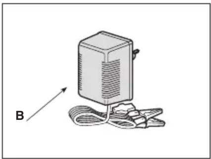
[58.B] Battery float charger
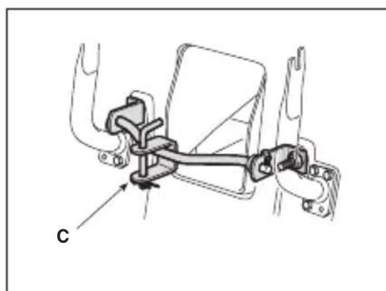
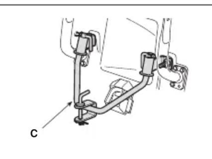
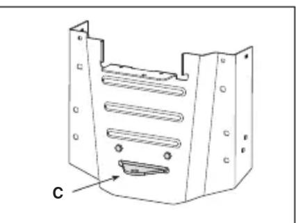
[58.C] Towing kit
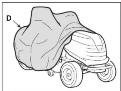
[58.D] Protective canvas cover
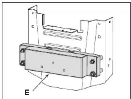
[58.E] Rear weights kit
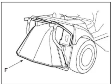
[58.F] Rear discharge safety kit (models with rear grass catcher only)
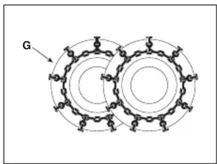
[58.G] Snow chains (18", 20")
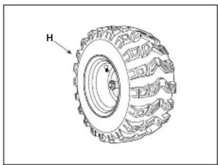
[58.H] Snow/mud wheels (18", 20")
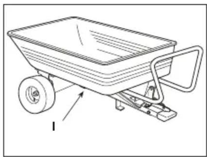
[58.1]Trailer
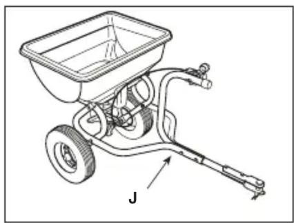
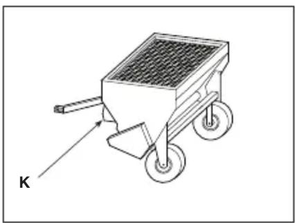
[58.J, 58.K] Sprinkler
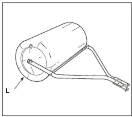
[58.L]Grassroller
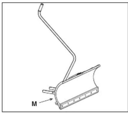
[58.M] Snow blade
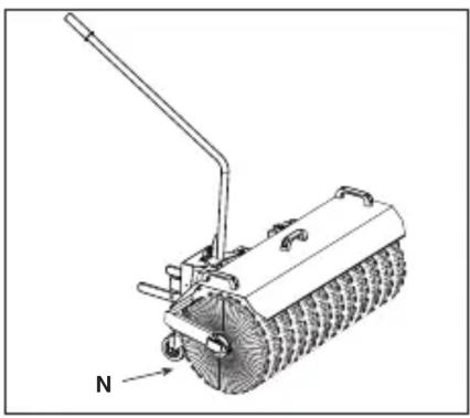
[58.N] Front sweeper
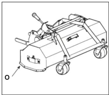
[58.O]Shredder
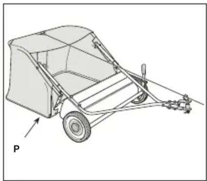
[58.P] (For SD series models only)
Leaf and collector 38"
Leaf and collector 42"
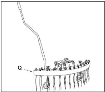
[58.Q] Front rake
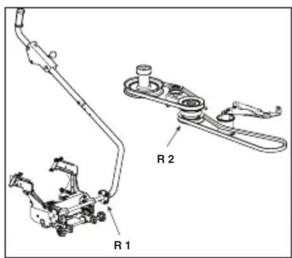
[58.R1, 58.R2] Lifting interface + Power Take-Off (PTO)
[58.R3] Power Take-Off (PTO)
* For specific information, refer to the information on the machine identification label.
[1] ES - DATOS TÉCNICOS
[2] Potencia nominal
[32.A] Tagumised tarvikud
[32.B] Eesmised tarvikud
[58] Valikulised tarvikud
[58.A1, 58.A2] Multšimiskomplekt
[1] FI - TEKNISET TIEDOT
[2] Nimellisteho
[1] LT - TECHNINIAI DUOMENYS
[2] Vardinè galia
[58.R1, 58.R2] Lift-interface + Aftakas (PTO)
[58.R3] Aftakas (PTO)
[58.A1, 58.A2] Sett for "mulching"
[58.L] Walec do trawy
[58.M] Pług śnieżny
[58.Q] Grade frontal
- USO DELLA MACCHINA 16
• Per modelli TS-TX-TH
6. USO DELLA MACCHINA
15.1 KIT PER MULCHING
7.4 Anti-scalp točkovi 22
7.5 Akumulator....22
7.6 Čišćenje 23
5.16 DISPLEJ I ZVUČNI SIGNAL TIPA "I"
5.17 DISPLEJ I ZVUČNI SIGNAL TIPA "II"
6.3 UPOTREBA NA STRMIM TERENIMA
6.5 PRACOVNÍ ČINNOST
5.16 DISPLAYTYPE "I" OG LYDSIGNALER
Når nøglen drejes over i positionen
5.17 DISPLAYTYPE "II" OG LYDSIGNALER
For at skifte position:
15.1 KIT TIL "MULTICLIP"
15.3 KIT TIL TRÆKNING
15.6 KIT HINTERER AUSWURFSCHUTZ
15.19 ZAPFWELLE (PTO)
15.20 ZAPFWELLE (PTO)
- XEIPISTHPIA EΛΕΓΧΟΥ 10
15.13 ΕΚΧΙΟΝΙΣΤΙΚΟ ΜΕ ΛΑΜΑ
-
GENERAL INFORMATION......2
-
SAFETY REGULATIONS......2
-
GETTING TO KNOW THE MACHINE......5
3.1 Description of the machine and planned use....5
3.2 Safety signs 5
3.3 Identification label 6
3.4 Main components 6
- ASSEMBLY....7
4.1 Assembly components......7
4.2 Steering wheel assembly 7
4.3 Seat assembly 8
4.4 Mounting and connecting the battery .... 8
4.5 Mounting the grass catcher supports .... 8
4.6 Removing the grass catcher retaining pawl 8
4.7 Mounting the rear bumper 8
4.8 Mounting the grass catcher bag......8
4.9 Mounting the grass catcher tipping levers 9
4.10 Mounting the side guards of the cutting device assembly (if any)....9
4.11 Side discharge chute assembly (for models with side discharge only) ...... 9
- CONTROLS....9
5.1 Brake pedal....9
5.2 Forward gear pedal 9
5.3 Reverse gear pedal 10
5.4 Hydrostatic drive release command .... 10
5.5 Key ignition switch....10
5.6 Throttle command....10
5.7 Parking brake lever....11
5.8 Headlights switch 11
5.9 Cutting device engage and disengage functions 11
5.10 Enable reverse gear cutting button.....12
5.11 Controls for adjusting the cutting unit assembly height....12
5.12Speedcruisecontrol 12
5.13 Counter (if fitted) 12
5.14 Auxiliary socket for accessories ..... 13
5.15 Grass catcher tipping command ..... 13
5.16 Type "I" display and buzzers.....13
5.17 Type "II" display and buzzers......13
- USING THE MACHINE....16
6.1 Preparation 16
6.2 Safety checks....17
6.3 Using on slopes 17
6.4 Start-up 18
6.5 Operation 18
6.6 Stop 20
6.7 After operation 20
- ROUTINE MAINTENANCE 20
7.1 General information....20
7.2 Refuelling / emptying the fuel tank..... 21
7.3 Check, top up, draining of engine oil ... 21
7.4 Anti-scalping wheels 22
7.5 Battery 22
7.6 Cleaning....22
7.7 Nuts and bolts 23
- EXTRAORDINARY MAINTENANCE ..... 23
8.1 Safety recommendations 23
8.2 Cutting device assembly 23
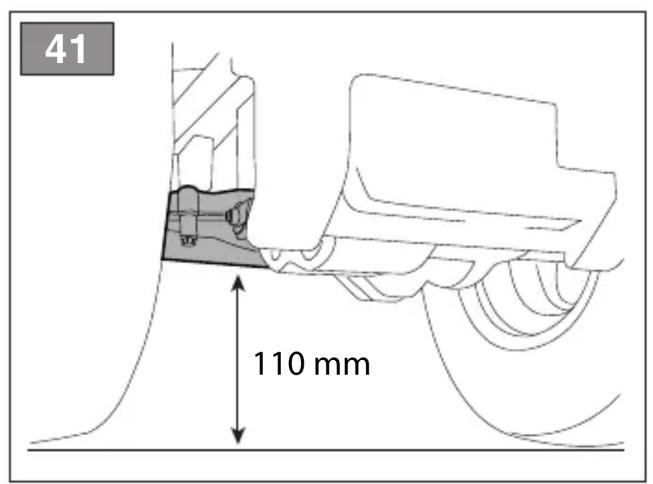
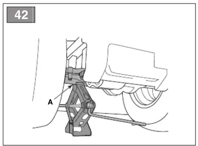
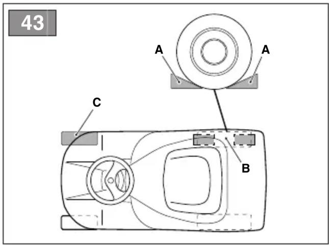
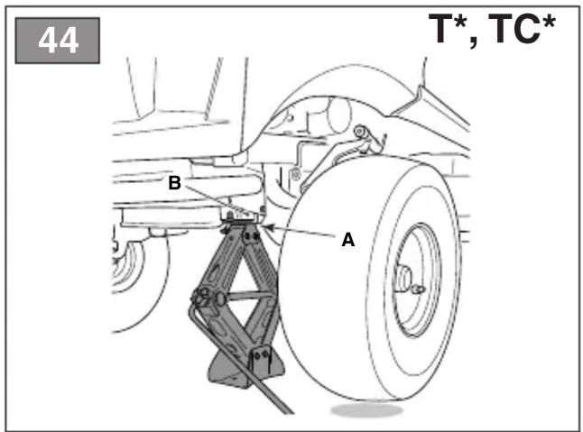
8.3 Replacing front / rear wheels....24
8.4 Electronic circuit board....25
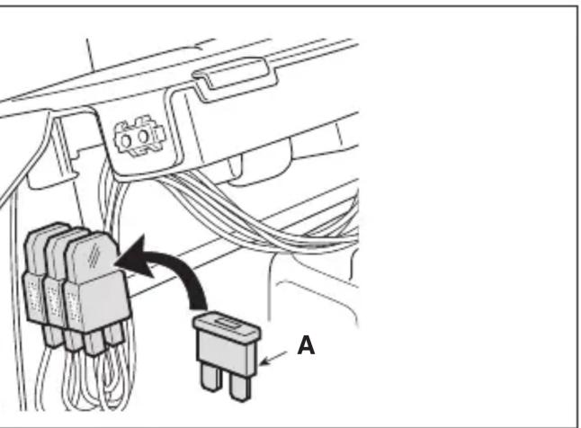
8.5 Replacing a fuse 25
8.6 Replacing bulbs 25
8.7 Rear drive unit....25
8.8 Front drive unit (4WD model) 26
8.9 Regulating the grass catcher retaining pawl spring....26
-
STORAGE 26
-
HANDLING AND TRANSPORTATION ..... 26
-
ASSISTANCE AND REPAIRS......26
12.WARRANTY COVERAGE 27
- MAINTENANCE TABLE......28
14.PROBLEM IDENTIFICATION 29
- ATTACHMENTS ...... 31
1.1 HOW TO READ THE MANUAL
Some paragraphs in the manual contain important information regarding safety and operation and are emphasized in this manner:
NOTE or IMPORTANT these give details or further information on what has already been said, and aim to prevent damage to the machine.
The symbol highlights danger. Non-compliance with the warning could lead to personal and/or third party injury and or damage.
The paragraphs highlighted in a square with grey spots indicate the optional characteristics not on all models documented in this manual. Check if the characteristic is on this model.
Whenever reference is made to a position on the machine "front", "back", "left" or "right" hand side, this refers to the operator's working position.
1.2 REFERENCES
The figures in these instructions for use are numbered 1, 2, 3, etc.
Components shown in the figures are marked A, B, C, etc.
A reference to component C in figure 2 is written: "See fig. 2.C" or simply "(Fig. 2.C)".
The figures are given as a guide only. The actual parts may vary from those shown.
1.2.2 Titles
The manual is divided into chapters and paragraphs. The title of paragraph “2.1 Training” is a sub-title of “2. Safety regulations”. References to titles or paragraphs are marked with the abbreviation chap. or par. and the relevant number. Example: “chap. 2” or “par. 2.1”
2. SAFETY REGULATIONS
2.1 TRAINING
⚠️ Become acquainted with the controls and the proper use of the machine. Learn how to stop the engine quickly. Failure to follow the warnings and instructions may result in fire and/or serious injury.
- Never allow children or persons unfamiliar with these instructions to use the machine. Local regulations may restrict the age of the operator.
- Never use the machine if the user is tired or unwell, or has taken medicine, drugs, alcohol or any substances which may slow his reflexes and compromise his judgement.
- Do not allow children or other passengers to ride on the machine.
- Bear in mind that the operator or user is responsible for accidents or unexpected events occurring to other people or their property. It is the user's responsibility to assess the potential risk of the area where work is to be carried out, and to take all the necessary precautions to ensure his own safety and that of others, particularly on slopes or rough, slippery and unstable ground.
- If the machine is sold or lent to others, make sure that the operator looks over the user instructions contained in this manual.
2.2 PREPARATION
Personal Protective Equipment (PPE)
- Always wear suitable work attire, hard-wearing safety footwear with non-slip soles and long trousers. Do not operate the machine when barefoot or wearing open sandals. Wear hearing protection devices.
- The use of hearing protection devices may reduce the operator's capacity to hear warnings (cries or alarms). Monitor the area in and around the working zone at all times.
- Never wear scarves, shirts, necklaces, bracelets, clothing with flowing parts, laces or ties or any hanging or flapping attachments that could catch in the machine or in any objects or materials in the work area.
- Tie your hair back if it is long.
Work area/Machine
- Thoroughly inspect the entire work area and remove anything that could be thrown by the machine or damage the cutting device/rotating units (stones, branches, iron wire, bones, etc.).
Internal combustion engines: fuel
⚠️ DANGER! The fuel is highly flammable.
- Keep the fuel in approved containers, in a safe place, away from any naked lights or heat sources.
- Keep the containers and storage area free of grass cuttings, leaves, or excessive grease.
- Keep the containers out of the reach of children.
- Do not smoke when filling up with fuel or when handling the fuel.
- Use a funnel to top up with fuel only in the open air.
- Do not inhale fuel fumes.
- Never remove the tank cap or add fuel while the engine is running or when the engine is hot.
- Open the fuel tank slowly to allow the pressure inside to decrease gradually.
- Do not approach the tank opening with a naked flame to check its contents.
- If you have spilt some fuel, do not attempt to start the engine but move the machine away from the area of spillage and avoid creating any source of ignition until the fuel has evaporated and fuel vapours have dissipated.
- Immediately clean up all traces of fuel spilt on the machine or on the ground.
- Replace caps of all fuel tanks and containers securely.
- Never start the machine in the same place in which you refilled it with fuel; the engine must be started in an area at least 3 metres from where you refuelled.
- If fuel is spilt on clothing, change clothing before starting the engine.
2.3 DURING OPERATION
Work Area
- Do not operate the engine in a confined space where dangerous carbon monoxide fumes can develop. All starting operations have to be carried out in an open or well ventilated area. Always remember that exhaust gases are toxic!
- When starting up the machine, do not direct the silencer and therefore the exhaust fumes towards flammable materials.
- Do not use the machine in environments at risk of explosion, in the presence of flammable
liquids, gas or powder. Electrical contacts and mechanical friction can generate sparks that can ignite the powder or vapours.
- Work only in daylight or with good artificial light in good visibility conditions.
- Keep persons, children and animals away from the working area. Instruct another adult to supervise any children in the vicinity.
- Avoid working with wet grass, in the rain and when there is a risk of a thunderstorm, especially lightening
- Pay careful attention to uneven ground (hills, dips), slopes, hidden hazards and obstacles that could limit visibility.
- Be very careful near ravines, ditches or embankments. The machine could overturn if a wheel slides over the edge or if the earth gives way.
- Pay attention on sloping ground which requires particular care to prevent overturning or loss of control of the machine. The main reasons for loss of control are:
- Insufficient wheel grip
- Excessive speed
- Inadequate braking
- Type of machine unsuitable for its task
– Lack of awareness of the effect of ground conditions, especially slopes
- Incorrect use as a towing machine.
- Be careful of traffic when operating the machine close to public roads.
- To avoid the risk of fire, do not leave the machine standing in high grass with the engine running.
Behaviour
- When working behind the wheel, do not become distracted and maintain the required level of concentration.
- Exercise caution when reversing or moving backwards. Look behind you to make sure there are no obstacles before and during operations in reverse gear.
- Use care when pulling loads or using heavy equipment:
– Use approved draw-bar hitch points only when towing;
– Limit loads to those that can be handled safely;
- Do not turn sharply. Take care when reversing;
- Use counterweight(s) or wheel weights whenever advised in the owner's manual.
- Pay attention when using the grass catcher and attachments that can alter the stability of the machine, especially on slopes.
-
Always keep hands and feet away from the cutting device, when starting and when using the machine.
-
Attention: the cutting device will continue to rotate for a few seconds after disengagement or after you have switched off the engine.
- Pay attention to cutting device assembly with more than one cutting mean, as rotating cutting device can trigger the rotation of the others.
- Keep away from the discharge opening.
- Do not touch the engine parts which heat up during use. Burns hazard.
- To avoid the risk of fire, do not leave the machine standing in high grass with the engine running.
⚠️ If something breaks or an accident occurs during work, turn off the engine immediately and move the machine away to prevent further damage; if an accident occurs with injuries or third parties are injured, carry out the first aid measures most suitable for the situation immediately and contact the medical authorities for any necessary health care. Carefully remove any debris which could cause damage or injury to persons or animals if ignored.
Use limitations
- Never operate the machine with guards damaged, missing or incorrectly assembled (grass catcher, side discharge guards rear discharge guards)
- Don't use the machine if the attachments/tools are not installed in their seats.
- Never disengage, deactivate, remove or tamper with the safety systems/micro-switches installed.
- Do not alter the engine regulator settings, or run it at overspeed. Excessive engine speeds increase the risk of injury to operators and other persons.
- Do not strain the machine too much and do not use a small machine for heavy-duty work. If you use the right machine, you will reduce the risk of hazards and improve the quality of your work.
- The machine has not been approved for use on public roads. It must be used (as indicated by the highway code) in private areas closed to traffic.
Ensure regular maintenance and correct storage to maintain machine safety and high performance levels.
Maintenance
- Never use the machine with worn or damaged parts. Faulty or worn-out parts must always be replaced and never repaired.
- To reduce the risk of fire, regularly check the machine for oil and/or fuel leaks.
- Be careful during adjustment of the machine to prevent entrapment of the fingers between moving parts of the cutting device and fixed parts of the machine.
The noise and vibration levels shown in these instructions are the maximum levels for use of the machine. The use of an unbalanced cutting device, the excessive speed of movement, or the absence of maintenance have a significant influence on noise emissions and vibrations. Consequently, it is necessary to take preventive steps to eliminate possible damage due to high levels of noise and stress from vibration. Maintain the machine well, wear ear protection devices, and take breaks while working.
Storage
- Do not store the machine with fuel in the tank in an area where fuel vapours could reach a naked light, a spark or a strong heat source.
- To reduce fire risks, do not leave containers with debris inside a room.
2.5 ENVIRONMENTAL PROTECTION
Safeguarding the environment must be a relevant and priority aspect of machine use, of benefit to the community and the environment we live in.
- Avoid being a disturbance to the neighbourhood. Use this machine at reasonable times of the day only (not early morning or late evening when the noise could cause disturbance).
- Adhere strictly to the local regulations governing the disposal of packaging, oil, fuel, filters, damaged parts or any other element which may have an impact on the environment; this waste should not be disposed of along with standard household waste, but must be disposed of separately and sent to special waste disposal facilities for handling and recycling.
- Comply with local regulations for the disposal of waste materials
- When the machine is withdrawn from service, do not dispose of it in the environment, but take it to a waste disposal facility in accordance with the local regulations in force.
3. GETTING TO KNOW THE MACHINE
3.1 DESCRIPTION OF THE MACHINE AND PLANNED USE
This machine is a ride-on lawn mower with seated operator.
The machine is equipped with an engine which drives cutting device protected by a casing, as well as a transmission unit that moves the machine.
The machine is equipped with:
- a two wheel (2WD) or four wheel (4WD) hydrostatic drive system, with infinitely variable forward and reverse gear ratios.
The operator is able to operate the machine and use the main controls, always seated in the operator's position.
The safety devices installed on the machine will disengage the engine and cutting device in a couple of seconds (par. 6.2.2).
3.1.1 Intended use
This machine was designed and built to cut grass.
Generally speaking this machine can:
- mow grass and collect it in the grass catcher bag.
- mow grass and deposit it on the ground via the rear.
- mow, chop and deposit the grass on the ground (mulching effect).
- mow the grass and deposit it on the ground laterally.
The use of special attachments provided for by the Manufacturer as original equipment or which may be purchased separately, allows this work to be done in various operating modes, illustrated in this manual or the instructions that accompany the single attachments. Likewise, the intended use can be extended to include other functions by applying
supplementary attachments (if provided for by the Manufacturer), abiding by the restrictions and conditions indicated in the instructions accompanying the attachment.
3.1.2 Improper use
Any other usage not in keeping with the aforementioned ones may be hazardous and harm persons and/or damage things. Examples of improper use may include, but are not limited to:
- allowing children, animals or other passengers to ride on the machine as they could fall off and injure themselves or compromise safe driving by the operator;
– towing or pushing loads without the use of the specified attachment for towing;
– using the machine for riding over unstable, slippery, icy, stony, rough, marshy ground or puddles that do not allow the consistency of the ground to be assessed;
– using the cutting device on surfaces other than grass;
– using of the machine for leaf or debris collection.
IMPORTANT Improper use of the
machine will invalidate the warranty, relieve the Manufacturer from all liabilities, and the user will consequently be liable for all and any damage or injury to himself or others.
3.1.3 User types
This machine is intended for use by consumers, i.e. non-professional operators. The machine is intended for "DIY" use only.
IMPORTANT The machine must
be used by one operator.
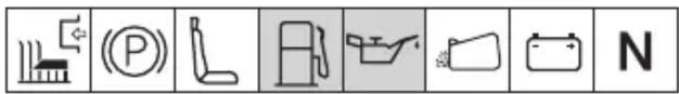
3.2 SAFETY SIGNS
Various symbols appear on the machine (fig. 2). They are used to remind the operator of the behaviour to follow to use it with the necessary attention and caution.
Meaning of symbols:


Warning! Read the instructions before use.


Warning! Remove the key and read the instructions before carrying out any maintenance or repair work.


Danger! Ejected objects: Do not operate without either the rear discharge guard or the grass catcher being in place. (for models with rear collection system only).

Danger! Ejected objects: Ensure persons remain at a safe distance.


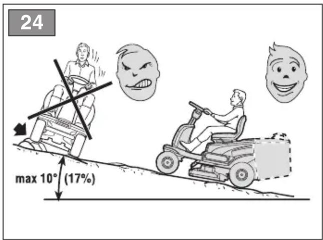
Danger! Machine rollover: Do not use the machine on gradients in excess of 10^ .

Danger! Dismemberment: Make sure that children remain at a safe distance from the machine when the engine is running.

Cutting risk. Cutting device in operation. Do not insert hands or feet into the cutting device housing.


Warning! Keep away from hot surfaces.

Do not climb on the machine by treading on the cutting device assembly protection panels.
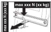
When using the towing kit, do not exceed the load limits indicated on the label, and respect the applicable safety regulations.
IMPORTANT Any damaged or illegible decals must be replaced. Order replacement decals from an Authorised Service Centre.
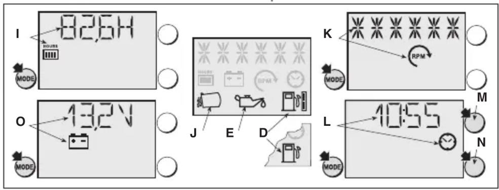
3.3 IDENTIFICATION LABEL
The identification label includes the following data (fig. 1):
- Sound power level
- Conformity marking
- Year of manufacture
-
Type of machine
-
Serial number
-
Name and address of Manufacturer
-
Article code
-
Nominal power and maximum operating engine speed
-
Machine weight with empty tank in kg
-
Type of transmission
Write the identification data of the machine in the specific space on the label on the back of the cover page.
IMPORTANT Quote the information on the product identification label whenever you contact an Authorised Service Centre.
IMPORTANT The example of the Declaration of Conformity is provided on the last page of the manual.
3.4 MAIN COMPONENTS
The machine consists of a series of main components, which perform the following functions (fig. 1):
A. Engine: this moves the cutting device and drives the wheels. Its specifications and regulations for use are described in a specific manual.
B. Cutting device assembly: this is the assembly comprising the casing that houses the rotating cutting device, and the cutting device.
C. Cutting device: these are what cut the grass; the fins at the ends help convey the cut grass towards the discharge chute.
D. Rear discharge guard (available upon request): this can be fitted in place of the grass catcher and prevents objects from being drawn up by the cutting device and hurled away from the machine. (for rear collection models only).
E. Side discharge chute: in addition to depositing the grass on the ground laterally, the side chute also constitutes a safety element, since it prevents any objects picked up by the cutting device from being projected long
distance from the machine (for models with side discharge function only).
F. Grass catcher: in addition to collecting the mown grass, the grass catcher also constitutes a safety element, since it prevents any objects picked up by the cutting device from being projected long distance from the machine (for models with rear collector only).
G. Discharge chute: this is the part connecting the cutting device assembly to the grass catcher (for models with rear collector only).
H. Driving seat: this is where the machine operator sits. It has a sensor connected to safety devices for detecting the presence of the operator.
I. Steering wheel: turns the front wheels.
J. Front bumper: this protects the front section of the machine.
K. Battery: provides the energy for starting the engine. Its specifications and regulations for use are described in a specific manual.
4. ASSEMBLY
The safety regulations to follow are described in chap. 2. Strictly comply with these instructions to avoid serious risks or hazards.
For storage and transport purposes, some components of the machine are not installed in the factory and have to be assembled after unpacking. Follow the instructions below.
⚠ Unpacking and completing the assembly should be done on a flat and stable surface, with enough space for machine handling and its packaging, always making use of suitable equipment. Do not use the machine until all the indications provided in the “ASSEMBLY” section have been carried out.
4.1 ASSEMBLY COMPONENTS
The packaging holds the components needed for assembly as listed in the table below:
| Description |
| 1 Steering wheel |
| 2 Dashboard cover and steering wheel assembly parts |
| 3 Driving seat |
| 4 Front bumper (if fitted) |
| 5 Bag with mounting screws etc. and instructions TS-TX-TH models only) (models with rear collector only) |
| 6 Grass catcher bag supports and associated attachments (models with rear collector only) |
| 7 Side discharge chute (for models with side discharge only) |
| 8 Cutting device assembly side strengtheners (if fitted). |
| 9 Envelope containing:- the instruction manuals and documents- driving seat assembly screws- side discharge chute assembly fittings (for models with side discharge only)- the connection screws for the battery cables- 2 starter keys- 1 spare 10 A fuse |
| 10 Mulching kit (models with side discharge function only) (if fitted). |
4.1.1 Unpacking
- Carefully open the packaging, paying attention not to lose components.
- Consult the documentation in the box, including these instructions.
- Remove all the unassembled parts from the box.
- Remove the machine from the packaging taking the following precautions:
- move the cutting device assembly to its maximum height (par. 5.11) to protect it against damage when the machine is lifted off the base pallet;
- Lift the machine off the base pallet.
- Move the front drive release lever to the released position (par. 5.4).
4.2 STEERING WHEEL ASSEMBLY
- Put the machine on a flat surface and straighten the front wheels.
- Using a screwdriver, remove the central cap (fig. 3.B) from the steering wheel (fig. 3.A).
- Fit the steering wheel (fig. 3.A) onto the protruding shaft (fig. 3.C), rotate it so that the spokes are facing the seat and then push it so that the steering wheel hub couples with the protruding end of the pin (fig. 3.D).
- Secure the steering wheel using the screw (fig. 3.E) and the washers (fig. 3.F) e (fig. 3.G) supplied, in the indicated sequence.
-
Tighten the screw (fig. 3.E) fully using a socket wrench.
-
Replace the cap on the steering wheel (fig. 3.B) inserting it so that it clicks into place.
4.3 SEAT ASSEMBLY
Pull the regulator lever up (fig. 4.C) and slide the seat (fig. 4.A) into the guide (fig. 4.B) from the steering wheel side, until it clicks into one of the six positions.
At this point, the seat has been mounted securely, so that it cannot be removed again without pressing the release lever (fig. 4.D).
4.4 MOUNTING AND CONNECTING THE BATTERY
The battery (fig. 5.A) is housed under the seat and secured by a spring (fig. 5.B).
- First connect the red wire (fig. 5.C) to the positive pole (+) and then the black wire (fig. 5.D) to the negative pole (−), using the screws supplied as shown.
- Mount the battery retaining spring (fig. 5.B), making sure that the cables are routed correctly in front of the battery, so that they are not pinched by the spring (fig. 5.B).
IMPORTANT Always fully charge the battery according to the instructions in the battery booklet.
IMPORTANT To avoid tripping the electronic board protection device, never attempt to start the engine if the battery is not fully charged
4.5 MOUNTING THE GRASS CATCHER SUPPORTS
Mount the two supports (fig. 6.A) on the rear plate (fig. 6.B), using the three screws (fig. 6.C) supplied for each support, as indicated, without locking the corresponding nuts (fig. 6.D).
Fasten the upper part of the grass catcher frame (fig. 6.E) to the supports and centre it with respect to the rear plate (fig. 6.B).
Adjust the position of the two supports (fig. 6.F) with respect to the stop (fig. 6.G) so that, by rotating the grass catcher frame, the stud (fig. 6.H) fits into the housing correctly (fig. 6.I).
Check again that the frame (fig. 6.E) is centred correctly with respect to the rear plate (fig. 6.B) and that it rotates correctly, as described above, then tighten the fastening screws (fig. 6.C) and nuts (fig. 6.D).
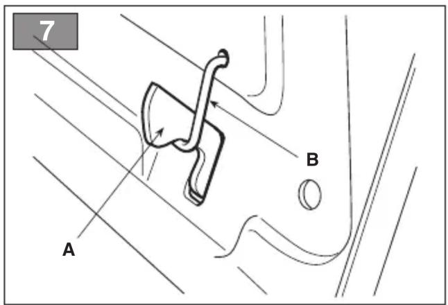
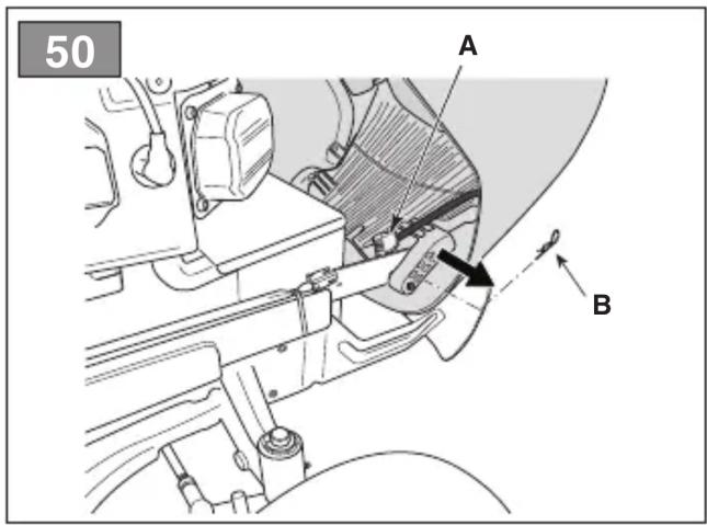
4.6 REMOVING THE GRASS CATCHER RETAINING PAWL
When the machine is shipped the grass catcher retaining catch (fig. 7.A) is secured to the rear plate by device of the hook (fig. 7.B). This must be removed before mounting the grass catcher bag supports and may no longer be used
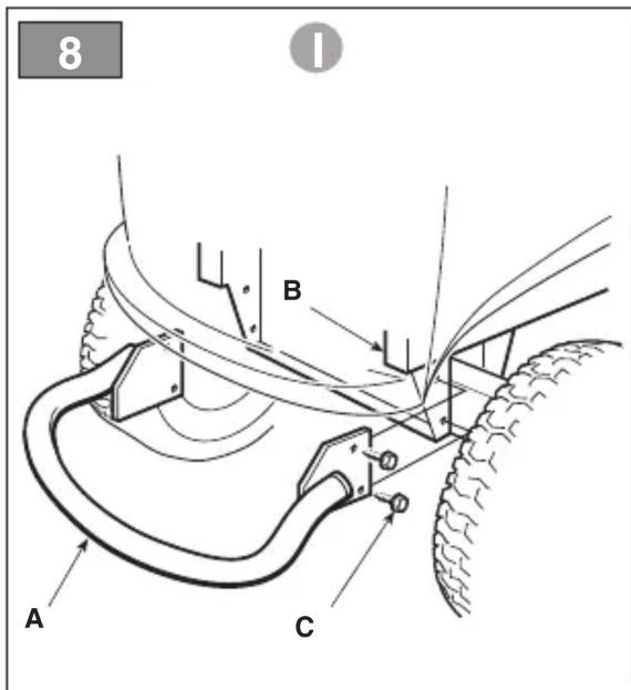
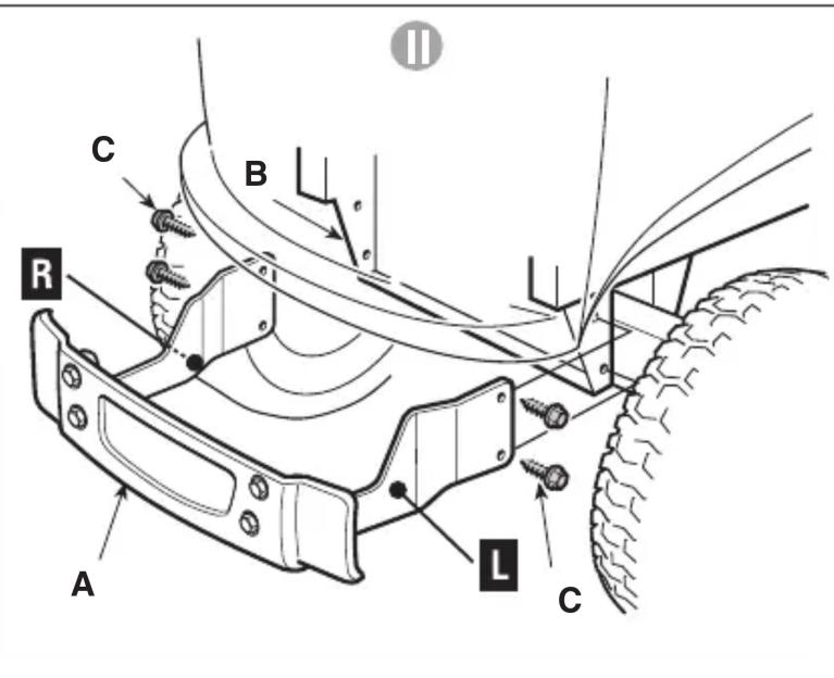
4.7 MOUNTING THE REAR BUMPER
4.8 MOUNTING THE GRASS CATCHER BAG
- For TC model
-
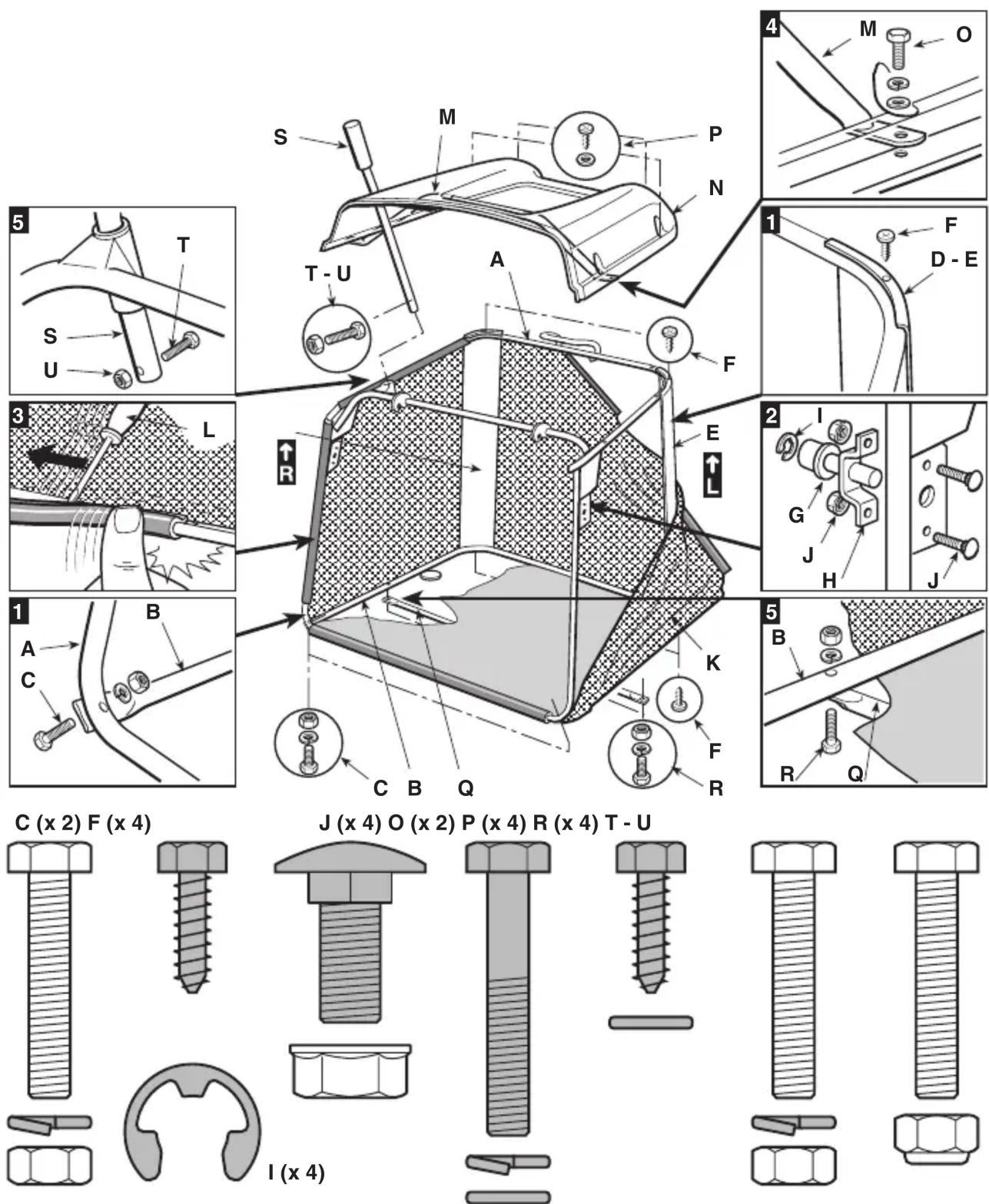
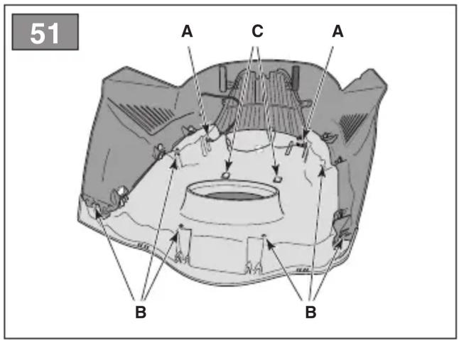
First assemble the frame, uniting the upper part (fig. 9.A) with the lower part (fig. 9.B), using the nuts and bolts supplied (fig. 9.C) as indicated. Position the angular plates (fig. 9.D) and (fig. 9.E), respecting the right (R↑) left (L↑) alignment, and securing them to the frame using four self-tapping screws (fig. 9.F).
-
Models with electrical tipping function only: Mount the two rollers (fig. 9.G) on the support pins (fig. 9.H), making sure that the catcher is facing the support, and secure it using elastic rings (fig. 9.I). Next, secure the supports to the front frame (fig. 9.B) using the nuts and bolts (fig. 9.J).
-
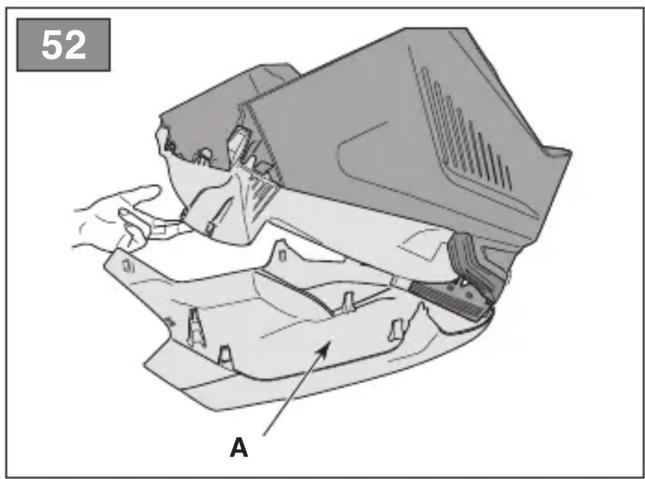
Insert the frame into the canvas cover (fig. 9.K), making sure that it is positioned correctly around the base. Attach the various plastic profiles to the frame tubes using a screwdriver (fig. 9.L).
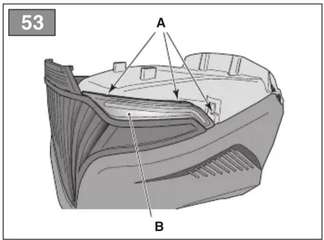
- Insert the handle (fig. 9.M) via the holes on the cover (fig. 9.N), and secure the resulting sub-assembly to the frame using the screws (fig. 9.O) as indicated, and the rear self-tapping screws (fig. 9.P).
- Mount the strengthening cross bar (fig. 9.Q) under the frame using the nuts and bolts (fig. 9.R), so that the flat part is facing the canvas. Insert the emptying lever (fig. 9.S) into its housing and fit the retaining screw (fig. 9.T) and associated nut (fig. 9.U).
• TS-TX-TH models
Complete the grass catcher mounting sequence as described in the instruction sheets supplied with the components.
4.9 MOUNTING THE GRASS CATCHER TIPPING LEVERS
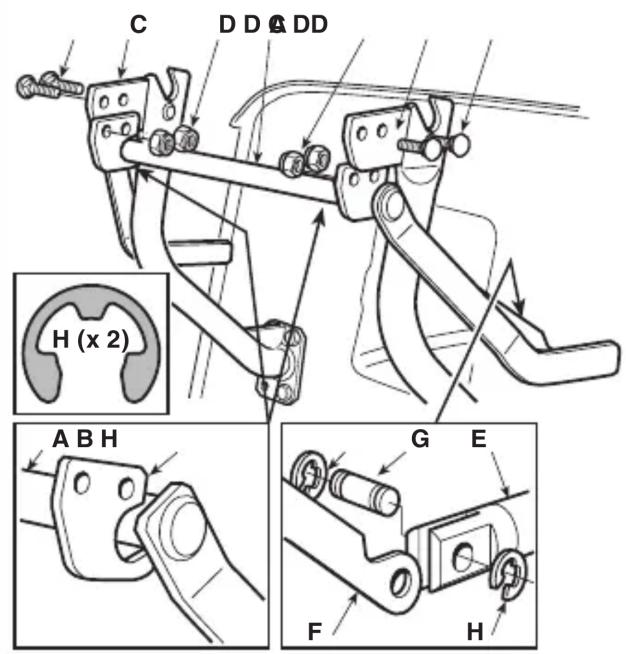
Position the lever shaft (fig. 10.A) so that it lies in the groove in the two plates (fig. 10.B) and secure it to the inner part of the grass catcher bag supports (fig. 10.C), using the nuts and bolts (fig. 10.D) supplied in accordance with the sequence indicated in the figure. Connect the end of the lifting piston shaft (fig. 10.E) to the lever (fig. 10.F) by using the pin (fig. 10.G) and mount the two elastic rings (fig. 10.H). Before mounting the grass catcher bag on its support, make sure that tipping levers move correctly.
4.10 MOUNTING THE SIDE GUARDS OF THE CUTTING DEVICE ASSEMBLY (IF ANY)
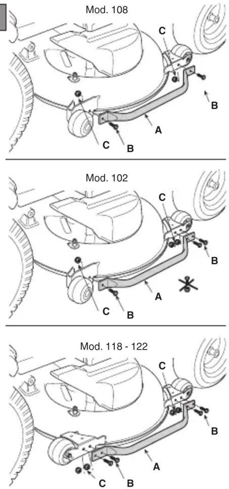
Mount the safety panels (fig. 11.A) using the screws (fig. 11.B) and nuts (fig. 11.C) supplied, in accordance with the instructions provided for each machine type.
4.11 SIDE DISCHARGE CHUTE ASSEMBLY (FOR MODELS WITH SIDE DISCHARGE ONLY)
-
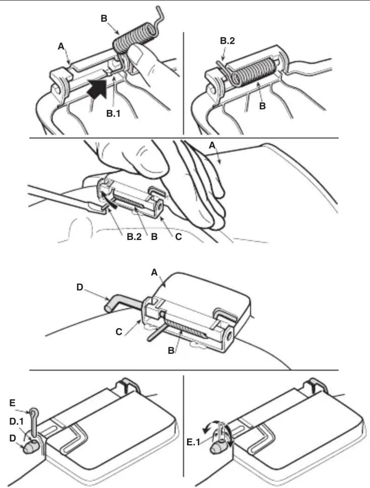
From the inside of the side discharge chute (fig. 12.A), fit the spring (fig. 12.B) by inserting the terminal (fig. 12.B.1) into the hole and turning it so that both the spring (fig. 12.B) and the terminal (fig. 12.B.2) are securely positioned in their housings.
-
Position the side discharge chute (fig. 12.A) in line with the cutting device assembly brackets (fig. 12.C). Using a screwdriver, turn the second terminal (fig. 12.B.2) of the spring (fig. 12.B) to bring it outside the side discharge chute.
-
Fit the pin (fig. 12.D) in the holes on the brackets (fig. 12.C) and on the side discharge chute, so that it passes through the coils of the spring (fig. 12.B) and the drilled end comes out of the inner most bracket.
- Insert the cotter pin (fig. 12.E) into the hole (fig. D.1) on the pin (fig. 12.D) and rotate the pin in order to bend the two ends (fig. 12.E.1) of the cotter pin, (with the aid of a pair of pliers), so that it cannot slide out, causing the pin (fig. 12.D) to disengage.
⚠️ Check that the spring works correctly and keep the side discharge chute securely lowered. Make sure that the pin is fitted properly to prevent it from falling out accidentally.
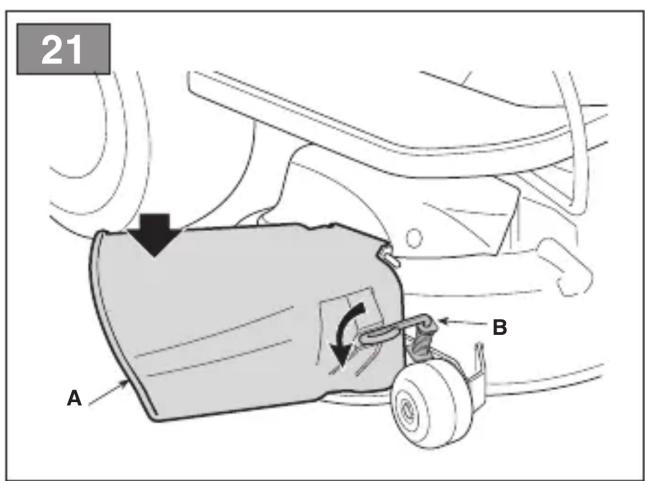
IMPORTANT For models with optional side unloading: make sure that the side unloading guard (Fig. 21.A) is lowered and locked by the safety lever (Fig. 21.B).
IMPORTANT Before disassembling or servicing the deflector, always push the safety lever (Fig. 21.B) and lift the side unloading guard (Fig. 21.A) to allow disassembly.
NOTE To remove the deflector, perform assembly steps in reverse order.
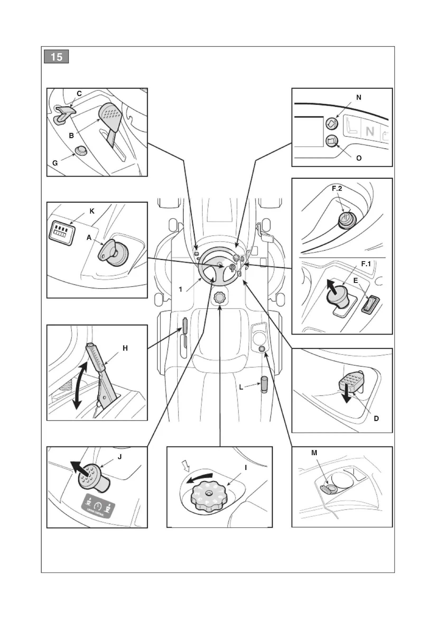
5. CONTROLS
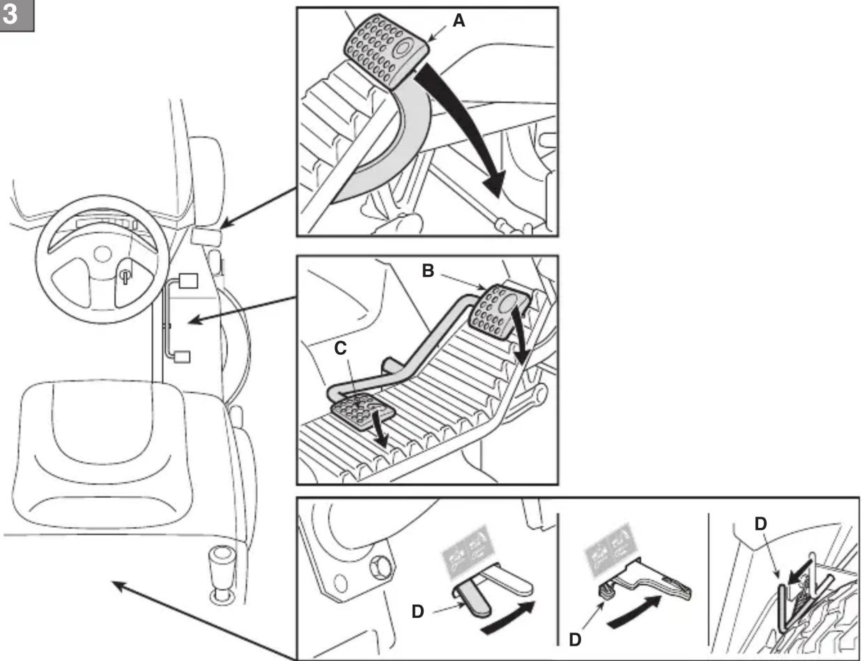
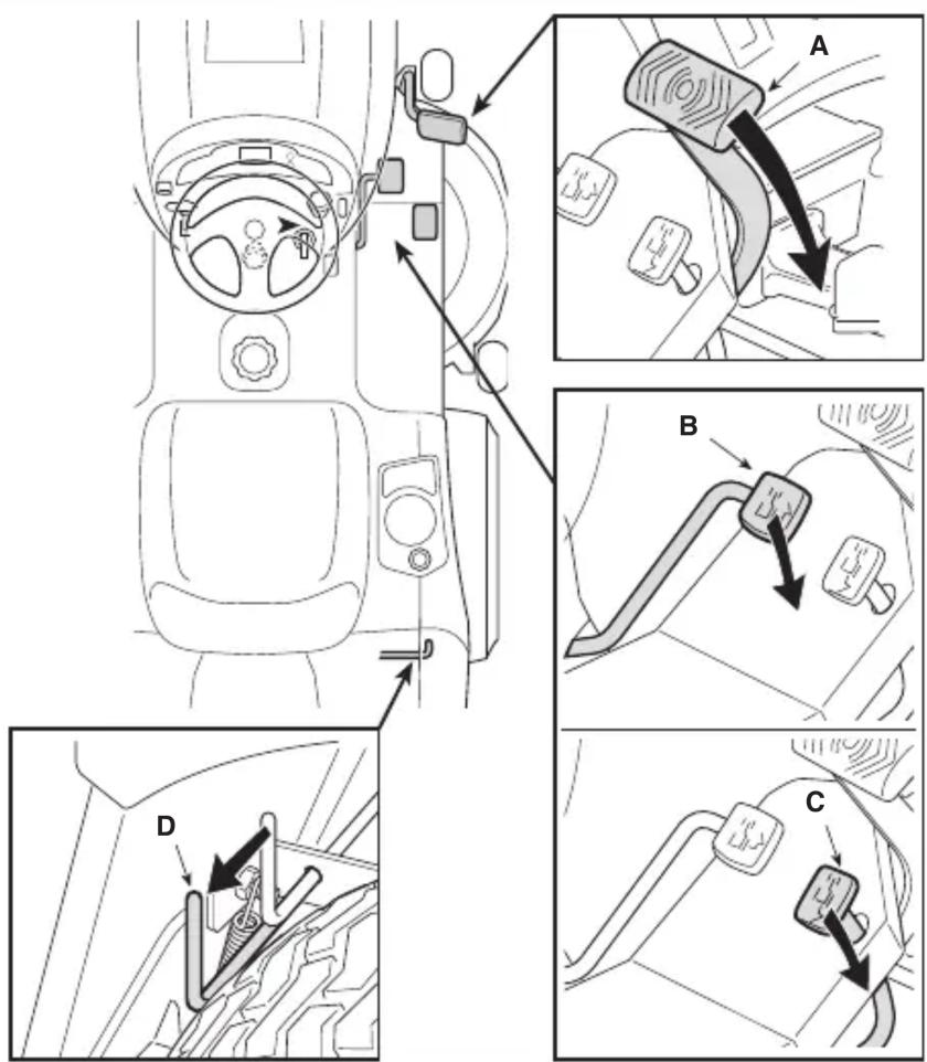
5.1 BRAKE PEDAL

This pedal operates the brakes on the rear wheels (fig. 13.A, 14.A)
5.2 FORWARD GEAR PEDAL
This pedal is used to apply traction to the wheels and regulate the speed of the machine when it is moving forward (fig. 13.B, 14.B):
-
Forward drive gear. Increasing the pressure on the pedal progressively increases the speed of the machine.
-
Neutral position. The pedal automatically goes into neutral position when released.
NOTE The "Neutral" condition is indicated by the lamp (fig. 16.F).
NOTE If the operator presses the pedal while the parking brake (fig. 13.D) is on, the engine stops.
5.3 REVERSE GEAR PEDAL
This pedal is used to apply traction to the wheels in reverse and regulate the speed of the machine (fig. 13.C, 14.C):
- Reverse gear. Increasing the pressure on the pedal progressively increases the speed of the machine.
Reverse must only be engaged when the machine has stopped.
- Neutral position. The pedal automatically goes into neutral position when released.
NOTE The "Neutral" condition is indicated by the lamp (fig. 16.F).
NOTE If the operator presses the pedal while the parking brake (fig. 15.D) is on, the engine stops.
5.4 HYDROSTATIC DRIVE RELEASE COMMAND
This command has two positions, as indicated on the label (fig. 13.D, 14.D):

- Drive engaged : for all uses, when moving and during cutting.


- Drive disengaged: this makes it much easier to move the machine by hand, with the engine turned off.

IMPORTANT To avoid damaging the drive unit, perform this operation only when the engine is stopped and the pedals (fig. 13.B, 13.C, 14.B, 14.C) are in the neutral position.
• 4WD model only
The machine may only be moved easily backwards, even if the rear drive is released.
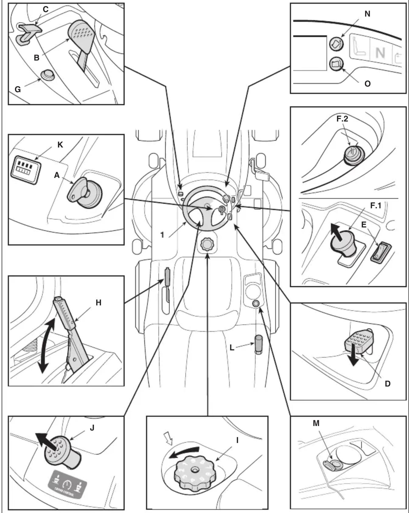
5.5 KEY IGNITION SWITCH
The key enables/disables the machine ignition
It has three positions (fig. 15.A):

- Stop position. The machine turns off immediately.

- On position. All functions are active.

- Start position. Switch on the starter motor to start the machine. If you release the key on start it will automatically return to On.
5.6 THROTTLE COMMAND
Regulates the engine's r.p.m.
Depending on the type of motor, there are two types of throttle control:
A. Type "I" with separate Choke command (Fig. 15.B + Fig. 15.C)
B. Type "II" (Fig. 15.B)
The positions shown correspond to:

- Choke Command - Cold start. (if fitted) This command is used to start the engine when it is cold. The «CHOKE» position enriches the mixture so it must only be used for the time necessary for cold starts.

- Maximum engine speed. To be used always when starting the machine, while it is On and during grass cutting operations.

- Minimum engine speed. Used when the engine is sufficiently warm during stationary periods of operation.
NOTE When moving from one area to another, place the lever in a position between "tortoise" and "hare".
NOTE Some models are equipped with a system that automatically controls
the choke position in the carburettor during engine ignition and heating.
This lever stops the machine from moving when it has been parked.
This lever has two positions (fig. 15.D), corresponding to:

- Brake not engaged. To release the parking brake, press the pedal (fig. 13.A, 14.A). The lever returns to the brake disengaged position.

- Brake engaged. To engage the parking brake, press the pedal down as far as it will go (fig. 13.A, 14.A) and move the lever to the brake engaged position. When you take your foot off the pedal it will be blocked in the lowered position.
5.8 HEADLIGHTS SWITCH

This button (fig. 15.E) is used to control the headlights when the key (fig. 15.A) is in the «ON» position.
5.9 CUTTING DEVICE ENGAGE AND DISENGAGE FUNCTIONS
This control is used to engage and disengage the cutting device by using of an electro-magnetic clutch:

- Cutting device engaged.
Mushroom type button pulled out (fig. 15.F.1) or button pressed (fig. 15.F.2).

- Cutting device disengaged.
Mushroom type button pressed (fig. 15.F.1) or button released (fig. 15.F.2).
When the cutting device are disengaged, a brake is applied simultaneously in order to stop them rotating within a few seconds.
NOTE The "Cutting device disengaged" condition is indicated by the lamp (fig. 16.A).
NOTE If you engage the cutting device without taking the necessary safety precautions, the engine shuts down and cannot be restarted (see par. 6.2.2)
Press and hold the button (fig. 15.G) to reverse while the cutting device are engaged, without causing the engine to stop.
5.11 CONTROLS FOR ADJUSTING THE CUTTING UNIT ASSEMBLY HEIGHT
• Control with lever
This lever is used to raise and lower the cutting device assembly, which may be positioned at 7 different cutting heights (fig. 15.H).

The seven positions for this lever, shown as «1» to «7» on the label, correspond to various cutting heights between 3 and 9 cm.

To change positions, press the release button on the end of the lever.

• Control with lever and knob
This lever (fig. 15.H) is used to raise and lower the cutting device assembly.
- Position «A»
Cutting device assembly raised.
- Position «B»
Cutting device assembly lowered.
The knob (fig. 15.1) is used to set the cutting device assembly to one of 9 different positions, corresponding to nine cutting heights between 2 and 10 cm.
- Set the lever (fig. 15.H) to position «A».
- Adjust the cutting height using the knob (fig. 15.1).
- Set the lever (fig. 15.H) to position «B» to move the cutting device assembly automatically to a pre-defined cutting height.
NOTE Set the lever (fig. 15.H) to position «A» during transport and shipping.
5.12 SPEEDCRUISECONTROL
This device is used to maintain the forward speed at the desired value, without having to maintain pressure on the pedal (fig. 13.B, 14.B).
The mushroom type control button has two positions:

- Pressed. Device disabled (deactivated)
-
Pulled out. Device enabled (active)
-
When the device is activated, the machine maintains the same forward speed, without having to operate the pedal (fig. 13.B, 14.B).
- The device cannot be used in reverse mode.
- The reverse pedal is disabled when this device is enabled (fig. 13.C, 14.C).
NOTE Speeds may vary with respect to the selected value when the machine is moving up or down slopes.
To deactivate the device and restore pedal speed control (fig. 13.B, 14.B) simply:
- press the pedal (fig. 13.B, 14.B);
or
- press the brake pedal (fig. 13.A, 14.A).
In both cases, the mushroom button will return automatically to the «Pressed» position.
IMPORTANT Never use the mushroom button to deactivate the device.
5.13 COUNTER (IF FITTED)
The counter (fig. 15.K) is activated whenever the key (fig. 15.A) is set to the «ON» position, and indicates the engine operating hours.
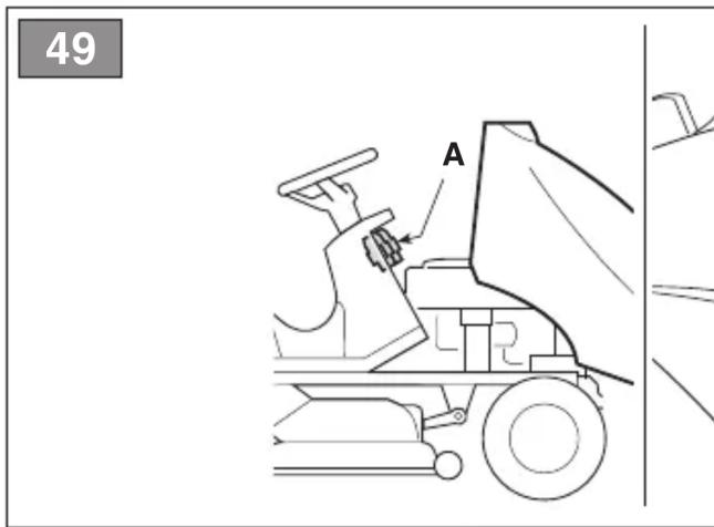
5.14 AUXILIARY SOCKET FOR ACCESSORIES
This socket can be used to connect electrical devices that run off a 12 Volt dc power supply, with a maximum power rating of 50 Watt, and fitted with a compatible plug (motoring type plug) (fig. 15.M).
- The socket is live only when the key (fig. 15.A) is in the «ON» position.
5.15 GRASS CATCHER TIPPING COMMAND
- Manual command
To tip the grass catcher bag in order to empty it, the operator must extract the lever (fig. 15.L) from its housing.
• Electrical command
To tip the grass catcher bag in order to empty it, the operator must press and hold the button (fig. 15.N) until the command motor stops running.
The grass catcher is returned to the working position by pressing and holding the button (fig. 15.O) until the retaining catch locks into place and the command motor stops running.
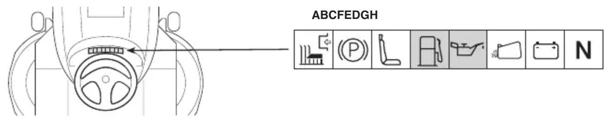
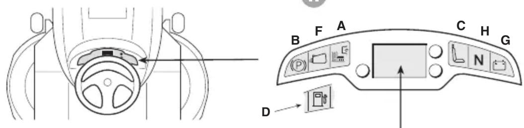
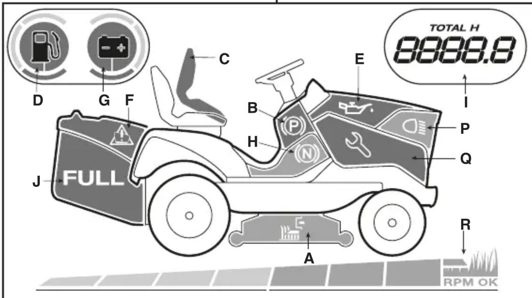
5.16 TYPE "I" DISPLAY AND BUZZERS
When the key is turned to the «ON» position, all the indicator lights switch on for about half a second (accompanied by a short acoustic signal) to indicate that they function correctly. Thereafter, these lights indicate:

Indicator light ON: cutting devices engaged (Fig. 16.A).

Indicator light ON: parking brake engaged (Fig. 16.B).

Indicator light ON: operator not present (Fig. 16.C).

Flashing indicator light: fuel is in reserve (Fig. 16.D).

Flashing indicator light: engine lubrication faults (Fig. 16.E). Stop engine immediately, check oil level and contact an Authorized Service Centre.

Indicator light ON: grass catcher or rear discharge guard missing (Fig. 16F);

Indicator light ON: when the engine is running there are battery re-charging faults (Fig. 16.G).
Flashing indicator light before start-up: the battery is unable to start the engine. Contact an Authorized Service Centre (Fig. 16.G).

Indicator light ON: transmission in "neutral" (Fig. 16.H).
• Acoustic signals - Buzzer
There are two types of acoustic signal:
- Continuous acoustic signal:
• Electronic card protection system has intervened.
- The engine has been switched off for more than 30 seconds with the key in the "DRIVE" position.
- Intermittent acoustic signal:
- The grass catcher is full.
5.17 TYPE "II" DISPLAY AND BUZZERS
When the key is turned to the «ON» position, all the icons switch on for about half a second (accompanied by a short acoustic signal) to indicate that they function correctly, then the display goes into "Timer" mode.
Thereafter, these lights indicate:

Indicator light ON: cutting devices engaged (Fig. 16.A).

Indicator light ON: parking brake engaged (Fig. 16.B).

Indicator light ON: operator not present (Fig. 16.C).
Simple fuel indicator light (Fig. 16.D).

Flashing indicator light: fuel is in reserve.
Fuel indicator light with level indicator (Fig. 16.D).
The indicator light shows the fuel level in the tank in accordance with the following criteria:

Fuel level is between full and about half full.

Fuel level is between half full and reserve.

Fuel level is in reserve.
NOTE The reserve tank holds approximately 2 litres of fuel, which is sufficient for operating the machine for 30-40 minutes at nominal engine speed.

Flashing indicator light: engine lubrication faults (Fig. 16.E). Stop engine immediately, check oil level and contact an Authorized Service Centre.

Indicator light ON: Grass catcher or rear discharge guard missing (Fig. 16F) (only for models with rear grass catcher);

Indicator light ON: when the engine is running there are battery re-charging faults (Fig. 16.G).
Flashing indicator light before start-up: the battery is unable to start the engine. Contact an Authorized Service Centre (Fig. 16.G).

Indicator light ON: transmission in "neutral" (Fig. 16.H).
- Operating functions
Press the "MODE" button to access operating functions in sequence.

Hour meter (Fig. 16.1). Indicates the total number of engine operating hours.

Voltmeter (Fig. 16.O). Indicates the battery charge state.

Tachometer (Fig. 16.K) Indicates the engine speed as numerical values or a series of asterisks, corresponding to:
Displayed values:
< 1600 engine idling speed
< 2500 transfer speed
2500 cutting speed

engine idling speed

transfer speed

cutting speed
NOTE When the engine speed display is flashing, it indicates that the current engine speed is unsuitable for mowing grass.

Clock (if present) (Fig. 16.L) Indicates the time in 24 hour/day mode.
To set-up the clock, turn the ignition key to the «ON» position and, without starting the engine, proceed as follows:
- Press the "MODE" key repeatedly until the clock icon appears.
- Hold the "MODE" button pressed until the first two digits (hour) flash.
- Press one of the two side buttons (Fig. 16.K, L) to increase or decrease the setting by one unit.
- Press the "MODE" button until the other two digits (minutes) flash.
- Press one of the two side buttons to increase or decrease the setting by one unit.
- Press the "MODE" button to complete the setting.
NOTE The clock is powered by a back-up battery; when this battery goes flat, contact an Authorised Service Centre.
• Acoustic signals - Buzzer
There are two types of acoustic signal:
- Continuous acoustic signal:
• Electronic card protection system has intervened.
- The engine has been switched off for more than 30 seconds with the key in the "DRIVE" position.
- Intermittent • The grass catcher is full.
acoustic signal:
TYPE "III" DISPLAY AND BUZZERS
When the key is turned to the "DRIVE" position, all the icons switch on for about half a second (accompanied by a short acoustic signal) to indicate that they function correctly.
Thereafter, these icons indicate:

Icon ON: cutting devices engaged (Fig. 16.A).

Icon ON: parking brake engaged (Fig. 16.B).

Indicator light ON: operator not present (Fig. 16.C).
Fuel icon with level indicator (Fig. 16.D).
The icon indicates the fuel level in the tank in accordance with the following criteria:

Fuel level is between full and about half full.

Fuel level is between half full and reserve.

Fuel level is in reserve.
NOTE The reserve tank holds approximately 2 litres of fuel, which is sufficient to operate the machine for 30-40 minutes at nominal engine speed.

Icon ON: engine lubrication faults (Fig. 16.E). Stop engine immediately, check oil level and contact an Authorized Service Centre.

Icon ON: Grass catcher or rear discharge guard missing (Fig. 16F) (only for models with rear grass catcher);

Icon ON: The grass catcher is full and must be emptied (Fig. 16.F) (only for models with rear grass catcher).
Battery icon with level indicator (Fig. 16.G).

Icon ON: Battery is charging.

Icon ON: Battery voltage level is optimal.

Icon on with engine off: Indicates that the battery needs re-charging
Icon on with engine on: Indicates battery charging problems.

Flashing icon: The battery is unable to start the engine. You must contact an Authorized Service Centre.

Icon ON: transmission in "neutral" (Fig. 16.H).

Hour meter (Fig. 16.1). Indicates the total number of engine operating hours.

Headlights (Fig. 16.P). Icon ON: Indicates that the headlights are on.

Maintenance required (Fig. 16.Q). Icon ON: Routine maintenance indicator. The maintenance schedule to follow is described in section 13. The icon comes ON every 50 hours and remains ON for 1 hour.

Green Area (Fig. 16.R). The engine rotation speed is suitable for optimal grass cutting.
• Acoustic signals - Buzzer
There are two types of acoustic signal:
- Continuous acoustic signal: • Electronic card protection system has intervened.
- The engine has been switched off for more than 30 seconds with the key in the "DRIVE" position.
- Intermittent • The grass catcher is full.
acoustic signal:
6. USING THE MACHINE

The safety regulations to follow are described in chap. 2. Strictly comply with these instructions to avoid serious risks or hazards.
6.1 PREPARATION
Before starting to mow, it is necessary to carry out several checks and operations to ensure you can work efficiently and in maximum safety.
-
ensure the machine is level and resting safely on the ground:
-
select the appropriate operating mode (par. 6.1.4);
6.1.1 Filling with oil and fuel
IMPORTANT The machine is
supplied without engine oil or fuel.
Before using the machine check for fuel and the oil level (par. 7.2, par. 7.3). For refuelling and oil top-up methods and precautions follow the instructions given in (par. 7.2, par. 7.3) and in the engine handbook.
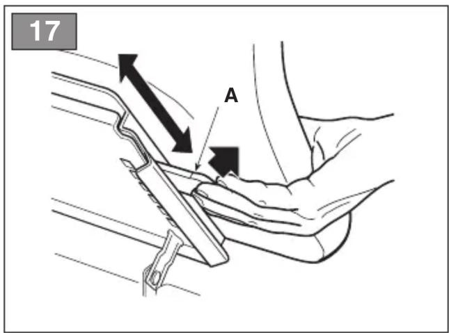
6.1.2 Seat adjustment
The sliding seat may be set to one of six different positions.
To adjust it, lift the handle (fig. 17.A), slide the seat and lock it in the desired position.
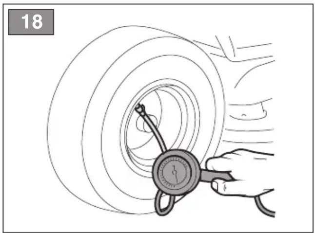
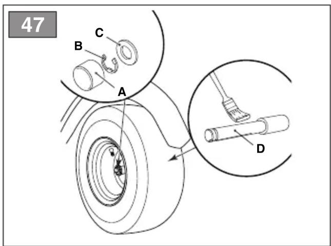
6.1.3 Tyre pressure
Having the right tyre pressure is the main condition for ensuring that the cutting device assembly is horizontal and mows evenly.
- Unscrew the valve caps
- Connect a compressed air line with a gauge to the valves (fig. 18)
- Adjust the pressure according to the values indicated in the "Technical Data" chart.
6.1.4 Preparing the machine before starting work
NOTE This machine can be used to mow lawns in a number of different ways; before starting work, prepare the machine based on how the lawn is to be mowed.
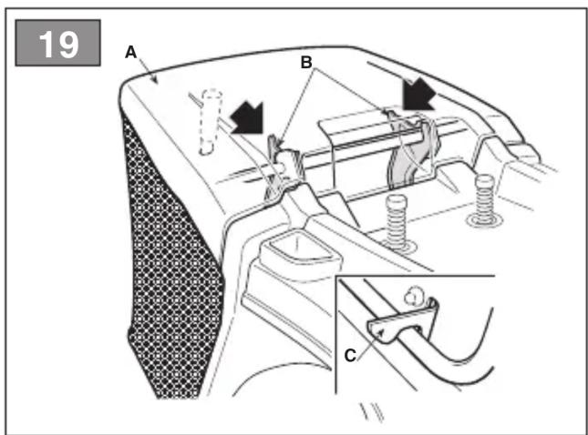
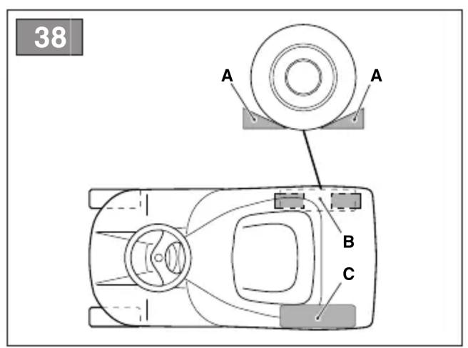
a. Preparation for grass cutting and collection in the grass catcher (for rear collection models only)
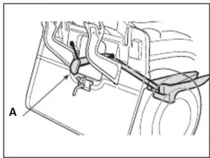
– Couple the grass catcher (fig. 19.A) to its supports (fig. 19.B) and centre it with respect to the plate, making sure that the two reference marks are aligned (fig. 19.B).
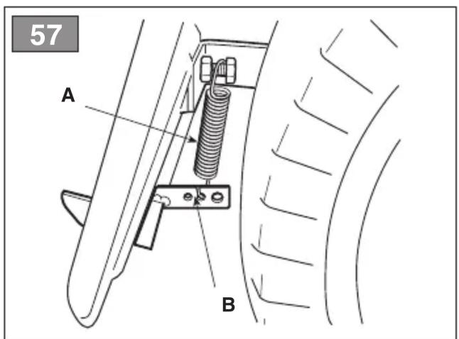
- Make sure that the lower pipe of the grass catcher opening is attached to the pawl (fig. 19.C).
- If the coupling is difficult or too loose, regulate the retaining spring (see 8.9).
b. Preparation for mowing and rear grass discharge (models with rear grass catcher only) (if fitted)
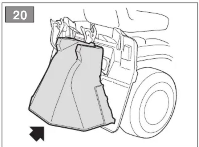
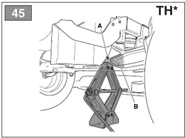
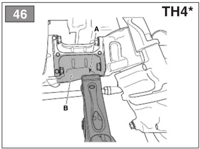
- If you decide to work without the grass catcher, a rear discharge guard kit is available upon request (Fig. 20, section 15.7) which must be securely mounted on the rear plate as indicated in the instructions provided.
c. Preparation for mowing and mulching of grass
- If you decide to mow the grass, mulching it and leaving it on the grass, a "mulching" kit is available upon request (chap. 15.1). This has to be attached to the rear plate as indicated in the instructions.

In the case of models with discharge, make sure that the total discharge support has been counted (fig. 22.A) (if fitted).
d. Prepare the machine for cutting and lateral grass discharge (for models with side discharge only):
– Always make sure that the spring inside the deflector (Fig. 21.A) and the safety lever (Fig. 21.B) operate correctly, holding it firmly in the lowered position.
- When cutting tall or wet grass, we recommend removing the lateral discharge strengthener (fig. 22.A) (if fitted).
- To remove the strengthener, undo the screws (fig. 22.B) while maintaining the side discharge chute in the raised position (fig. 22.C).

In the event of collisions without side discharge strengthener and (fig. 22.A), the cutting device embly may be deformed.

Always remember to replace the discharge strengthener after use.
6.1.5 Positioning the anti-scalping wheels
The anti-scalping wheels are used to reduce the risk of tearing up sections of lawn, which can occur when the edge of the cutting device assembly drags over irregular ground. Position the wheels as indicated (par. 7.4).
6.2 SAFETY CHECKS
Run the following safety checks and check that the results correspond to those outlined on the tables.

Always carry out the safety
checks before use.
6.2.1 General safety check
| Object Result | |
| Battery No damage to the | casing,cover or terminals |
| Rear discharge guard,grass catcher | Good condition. Nodamage. Properlyinstalled. |
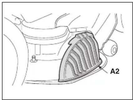
| Side dischargeguard, suction grid | Good condition. Nodamage. Properlyinstalled |
| Fuel lines andconnections. | No leaks. |
| Electrical cables. All insulat | on intact.No mechanical damage. |
| Oil lines No leaks. | No damage. |
| Safety devices Proceed as | indicatedin par. 6.2.2 |
6.2.2 Control of safety devices
The safety devices work in two ways:
A. they prevent the engine from starting if all the safety requirements have not been met;
B. by stopping the engine if even just one of the safety requirements is lacking.
| Action Result | |
| 1. gear in “neutral”;2. cutting device disengaged;3. operator seated. | The engine starts |
| the operator leaves his seat The engine stops |
| Action Result | |
| the grass catcher is lifted or the rear discharge guard removed without disengaging the cutting device (for rear collection models only) | The engine stops |
| the parking brake is engaged without disengaging the cutting device | The engine stops |
| the speed change is activated or the drive pedal with the parking brake engaged | The engine stops |
| the reverse gear is engaged with the cutting device engaged, without pressing the consent button (par. 5.10) | The engine stops |
| Drive the machine forwards and backwards, shift to neutral /release the drive pedal (par. 5.2; par. 5.3) | The machine slows down and stops |
| Press the brake pedal (par. 5.1) | The machine stops |
| Test driving No abnormal | vibrations.No abnormal sound |

If any of the results fail to match the indications provided in the tables, do not be the machine! Contact a service centre to ensure it checked and repaired if necessary.
IMPORTANT Always bear in mind that the safety devices prevent the engine from starting if safety requirements have not been met. In these cases, once the start consent has been reinstated, the ignition key (fig. 15.A) must first be turned back to Off before the engine can be restarted.
6.3 USING ON SLOPES
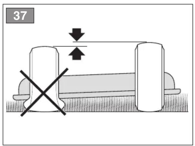
Comply with the limits indicated in the "Technical Data" Tables as in "fig. 24" regardless of the mowing direction.
Remember there is no such thing as a "safe" slope. Driving on grass slopes requires particular care. To prevent overturning or loss of control over the machine:
- Never mow across the face of the slope. Lawns on a slope have to be mowed moving up and down and never across them. When changing direction, take great care that the wheels facing the slope do not hit any obstacles (such as stones, branches, roots,
etc.) that may cause the machine to slide sideways, tip over or make you lose control.
- Do not stop or start suddenly when going up or downhill;
- Shift to drive gear very gently paying particular attention to prevent the machine from tipping up.
- Reduce speed:
- before changing direction
and during tight turns
- before facing a slope, particularly downhill
- Never switch to reverse gear to decrease speed when going downhill: this could cause loss of control of the machine, especially on slippery ground.
- Always engage the parking brake before leaving the machine at a standstill and unattended.
- In order to exploit the braking effect of the hydrostatic drive, when the transmission is not engaged, avoid pressing the drive pedal when moving down hill
6.4 START-UP
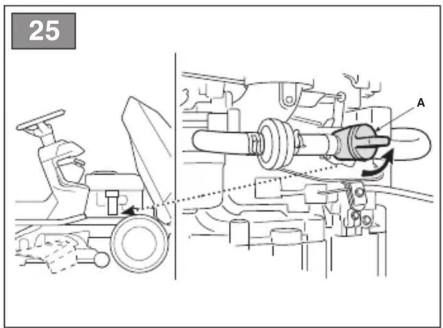
- Open the fuel tap (fig. 25.A) (if provided).
- Sit in the operator's position.
- Put the drive into neutral («N») (par. 5.2; par. 5.3).
- Disengage the cutting device (par. 5.9).
- Engage the parking brake (par. 5.7).
-
Shift the throttle control to maximum "hare" speed position (par. 5.6).
-
If cold starting: engage choke control (para 5.6) (if present).
-
Insert the key switch and turn it to the running position to engage the electric circuit. Wait for 2 seconds and turn it to the start-up position to start the engine.
-
Release the ignition key once the engine has started.
-
If cold starting: as soon as the engine ticks over:
10a. Deactivate the choke command (par. 5.6, type "II"), setting the accelerator command to the maximum speed - "hare" (if fitted).
10b. Deactivate the choke command (par. 5.6, type "I") (if fitted).
NOTE Using the choke when the engine is already warm can foul the spark plugs and cause the engine to run erratically.
- When the engine has started, shift the throttle control to the minimum «tortoise» speed position.
NOTE If there are engine starting problems, do not persist as you can risk running the battery flat and flooding the engine. Turn the key to the Off position, wait for a few minutes and then repeat the operation. If the malfunction persists, refer to the engine manual and chapter «14» in this manual.
6.5 OPERATION
6.5.1 Forward gear and riding without mowing
When moving the machine:
• disengage the cutting device (par. 5.9);
- set the cutting device assembly to the fully raised position (par. 5.11);
- shift the throttle control to a point midway between the «tortoise» and «hare» speed positions.
- release the parking brake by releasing the brake pedal (par. 5.7).
- press the drive pedal (par. 5.2) in the “forward” direction and accelerate to the desired speed by applying pressure to the pedal and operating the throttle.
⚠️ Drive must be engaged in accordance with the modes described (paragraph 5.2) to avoid sudden meshing, jerking start and loss of control of the vehicle, especially on slopes.
6.5.2 Braking
Reduce machine speed by decreasing the engine speed, then press the brake pedal (par. 5.1) to reduce the speed further, until bringing the machine to a standstill.
The machine can be significantly slowed down by releasing the drive pedal (section 5.2).
6.5.3 Reverse gear
IMPORTANT Reverse must be engaged when the machine has stopped.
- Press the pedal (par. 5.1) until the machine comes to a stop;
- Start reversing by pressing the drive pedal in the "R" direction (par. 5.3).
6.5.4 Grass cutting
To operate the machine proceed as described below:
- shift the throttle to the maximum speed position ("hare"); this position is always used when using the machine;
- bring the cutting device assembly to the highest position;
- engage the cutting device (par. 5.9) only on grass lawns; avoid engaging them on stony ground or when the grass is very high;
- When starting to cut grass, start off slowly and carefully, as described above;
- Regulate the speed and cutting height (par. 5.11) according to the lawn conditions (grass height, density and humidity) and the quantity of grass to be removed;
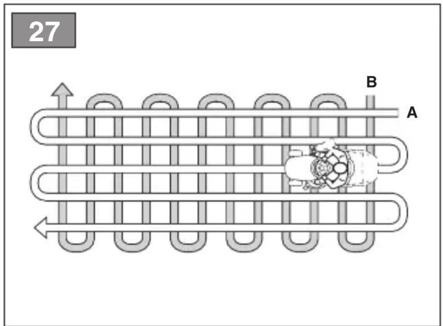
- The appearance of the lawn will be improved if the grass is always cut at the same height and in two alternating directions (fig. 27).
IMPORTANT To proceed in reverse gear with the cutting device engaged, it is necessary to press and hold the consent button (par. 5.10) so as not to cause the engine to stop.
Lower the speed whenever you note a drop in engine speed, since a forward speed that is too fast compared to the amount of grass being cut will never mow the grass well.
Disengage the cutting device and move the cutting device assembly to the highest position:
- When moving between work areas
- When driving on grass free surfaces
- Every time it is necessary to overcome an obstacle.
6.5.5 Suggestions for maintaining a nice lawn
- To keep a lawn green and soft with a good appearance, it should be cut regularly. A lawn can be composed of different types of grass. If the lawn is cut frequently, grass and roots grow more vigorously, forming a solid grassy bed. If the lawn is cut is less frequently, higher grass and weeds start growing (clover and daisies, etc.). The frequency of mowing should be in relation to the rate of growth of the grass, which should not be left to grow too much between one cut and the next.
-
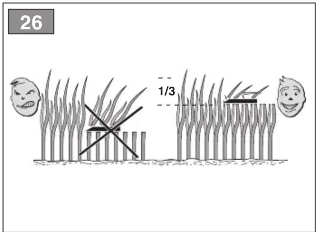
The best height of the grass on a well-kept lawn is approx. 4-5 cm and with one mowing, you do not need to remove more than a third of the total height. If the grass is very tall, it should be cut twice in a twenty-four hour period. the first cut should be carried out with the cutting device at the maximum height, and the second cut at the desired height (fig. 26).
-
If the cutting device are positioned too low, they will tend to rip the grass out by its roots, resulting in a "patchy" effect.
- During hot and dry periods, the grass should be cut a little higher to prevent the ground from drying out.
- It is always better to cut the grass when dry. Do not cut grass when wet; this may reduce the effectiveness of the cutting device, due to the grass getting stuck to it, and result in the grass being ripped out of the ground.
- The cutting device must be in good condition and well sharpened so that the grass is cut straight without a ragged edge that leads to yellowing at the ends.
- The engine must run at full speed, both to ensure a sharp cut of the grass and to get the necessary thrust to push the cuttings through the discharge chute.
- If the discharge chute tends to get blocked with grass, you should reduce the forward speed as it may be too high for the condition of the grass. If the problem persists, the probable causes are either badly sharpened cutting device or deformed fins.
- Be very careful when mowing near bushes or kerbs as these could distort the horizontal position of the cutting device assembly and damage its edge as well as the cutting device.
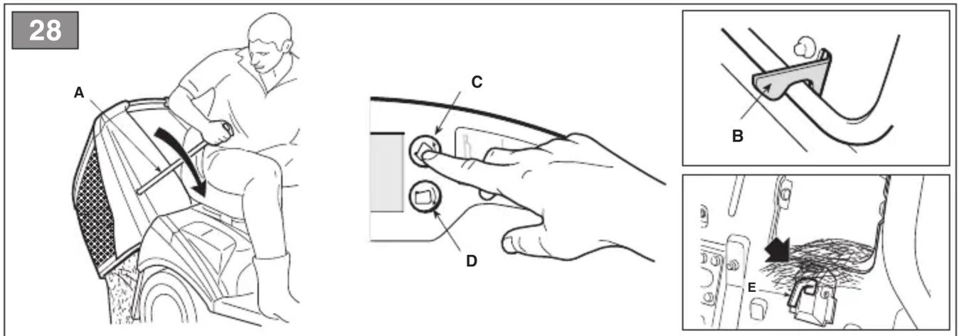
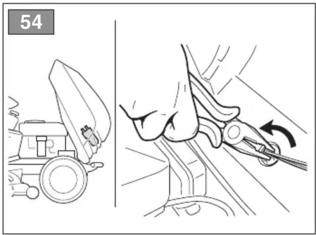
6.5.6 Emptying the grass catcher (for rear collection models only)
NOTE The emptying of the grass catcher can only be done with the cutting device disengaged, otherwise the engine stops.
- Manual command
- extract the lever (fig. 28.A) and tip the grass catcher bag up in order to empty it;
- close the grass catcher again so that it remains coupled to the pawl (fig. 28.B) and replace the lever.
- Electrical command
-
with the operator in the sitting position, press and hold the button (fig. 28.C) until the grass catcher bag is in the fully tipped position;
-
once the bag is empty, press and hold the button (fig. 28.D) until the grass catcher bag is fully lowered, make sure that it remains coupled to the pawl (fig. 28.B).
NOTE After emptying the grass catcher bag, the acoustic signal may be reactivated when the cutting device are engaged, this is caused by caused by traces of grass remaining attached to the indicator micro-switch sensor; if this happens, disengage and re-engage the cutting device immediately to silence the buzzer.
Ensure the sensor (fig. 28.E) is always kept free from traces of grass.
6.5.7 Cleaning the discharge chute (for rear collection models only)
- Cutting very tall or wet grass, particularly at excessively high speed, can clog up the discharge chute. If it clogs, follow the instructions provided in chap. 7.6.2.
6.5.8 Mowing completed
When mowing has been completed:
- disengage the cutting device;
- decrease the engine's r.p.m.
- drive back with the cutting device assembly in its highest position.
6.6 STOP
To stop the machine:
- shift the throttle lever to minimum "tortoise" speed position
⚠️ To avoid backfire, leave the throttle in the minimum "tortoise" speed position for 20 seconds before switching off the engine.
- switch off the engine by turning the ignition key to Off;
- with the engine turned off, close the fuel tap (fig. 25.A) (if provided);
- remove the key from the ignition
IMPORTANT To keep the battery charged, do not leave the ignition key in the «on» or «headlights on» position when the engine is not running.
The engine may be very warm immediately after it is shut off. Do not touch the exhaust or adjacent parts. This can cause burn injuries.
6.7 AFTER OPERATION
- Allow the engine to cool before storing in an enclosed space.
- Clean (par. 7.6).
- Make sure there are no loose or damaged components. If necessary, replace any damaged components and tighten loose screws or bolts, or contact an Authorised Service Centre.
IMPORTANT
– Lower the cutting device assembly;
- shift into neutral;
- engage the parking brake;
- stop the engine
– remove the ignition key (making sure that all moving parts have come to a complete stop);
- whenever the machine is left unattended, the operator dismounts from the driving seat or parks the machine;
7. ROUTINE MAINTENANCE
The safety regulations to follow are described in chap. 2. Strictly comply with these instructions to avoid serious risks or hazards.
⚠️ Before conducting any inspections, cleaning or maintenance/adjustment interventions on the machine:
• disengage the cutting device;
- shift into neutral;
• engage the parking brake;
- stop the engine;
- remove the key, (never leave the keys in the ignition or within reach of children or unauthorised persons);
• make sure that all moving parts have come to a complete stop;
- read the relevant instructions;
- use suitable clothing, protective gloves and goggles
- The frequency and types of maintenance are summarised in the "Maintenance Table". The table will help you maintain your machine's
safety and performance. It lists the main maintenance tasks and how often they need to be performed. Carry out the relevant task as soon as it is scheduled to be performed.
7.2 REFUELLING / EMPTYING THE FUEL TANK
IMPORTANT Observe the precautions provided in the engine owner's manual. Consult the engine owner's manual for the type of fuel to be used.
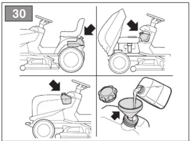
7.2.1 Refuelling
To refuel:
- Unscrew the fuel tank filler cap and remove it (fig. 30).
- Insert the funnel (fig. 30).
- Refuel being careful not to completely fill the tank.
- Remove the funnel.
- Close the fuel cap securely after refuelling and clean away any spills.
IMPORTANT Do not drip petrol onto the plastic parts to avoid ruining them. In the event of accidental leaks, rinse immediately with water. The warranty does not cover for damage to plastic parts of the bodywork or the engine caused by petrol.
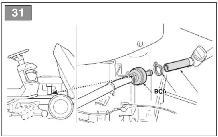
7.2.2 Emptying the fuel tank
NOTE Fuel is perishable and should not remain in the tank for more than 30 days. Empty the fuel tank before storing the machine for long periods of time (chap. 9).
⚠️ Allow the engine to cool before emptying the fuel tank.
- Place the machine on a flat surface, in the open air.
- Place a suitable container under the drain tube (fig. 31.A).
- Disconnect the tube (fig. 31.A) installed on the fuel filter inlet (fig. 31.B).
- Open the fuel tap (if provided)
- Collect the fuel in a suitable container.
- Reconnect the tube (fig. 31.A) making sure you position the clamp properly (fig. 31.C).
- Close the fuel tap (if provided).
The next time the machine is used, check that there are no fuel leaks from the tubes, fuel stopcock or carburettor.
7.3 CHECK, TOP UP, DRAINING OF ENGINE OIL
IMPORTANT Observe the precautions provided in the engine owner's manual. Consult the engine owner's manual for the type of oil to be used.
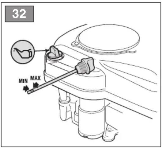
7.3.1 Check/top-up
⚠️ Always check the oil level before use.
Procedure:
- Make sure that the machine is level before performing the check.
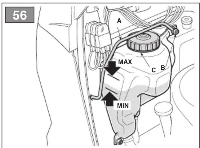
- Check the oil level: according to the instructions in the engine manual, this must be between the MIN and MAX marks on the dipstick (fig. 32).
Do not overfill as this could cause the engine to overheat. If the oil level exceeds the "MAX" mark, drain until the correct level is achieved.
7.3.2 Draining
To ensure that the machine functions correctly, and to guarantee a long working life, we recommend changing the engine oil at regular intervals, as indicated in the Owner's Manual supplied with the engine.
The oil may be very hot if removed just after the engine has been switched off. Consequently allow the engine to cool down for a few minutes before proceeding to drain off the oil.
Replace the engine oil according to the frequency indicated in the engine owner's manual.
Proceed as follows:
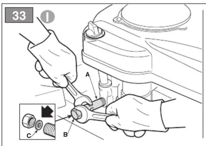
- Type "I"
- Place the machine on a flat surface.
- Place a suitable container under the extension tube (fig. 33.A).
- Hold the extension tube (fig. 33.A) firmly in place and unscrew the drain plug (fig. 33.B).
- Collect the oil in a suitable vessel.
- Replace the drain plug (fig. 33.B) making sure that the gasket is in the right position (fig. 33.C).
- Fully tighten holding the extension tube firmly in place (fig. 33.A).
- Clean up any spills.
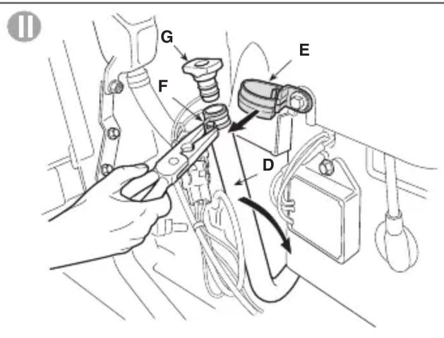
- Type "II"
- Place the machine on a flat surface.
- Place a suitable container under the extension tube (fig. 33.D).
- Detach the extension tube (fig. 33.D) from the support (fig. 33.E) then, using a pair of pliers, loosen the clamp fig. 33.F) until it is possible to extract the drain plug (fig. 33.G).
- Bend the extension tube and drain the oil into the container.
- Replace the drain plug (fig. 33.G) and reattach the extension tube (fig. 33.D) to the support (fig. 33.E) before refilling with oil.
- Clean up any spills.
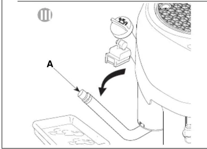
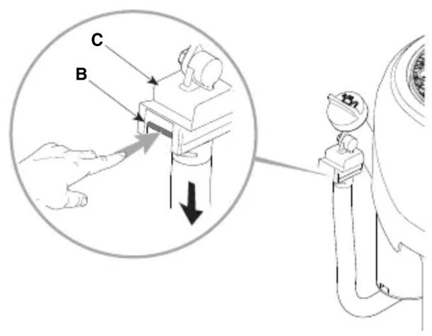
- Type "III"
- Place the machine on a flat surface.
- Place a suitable container under the extension tube (fig. 33.A).
- Press the cotter (fig. 33.B)
- Release the extension tube from the support by moving it downwards;
- Bend the extension tube and drain the oil into a suitable container.
- Refit the extension tube (fig. 33.A) on the support (fig. 33.C) before topping up the oil.
- Clean up any spills.
IMPORTANT Hand the spent oil over to a disposal facility in accordance with local provisions.
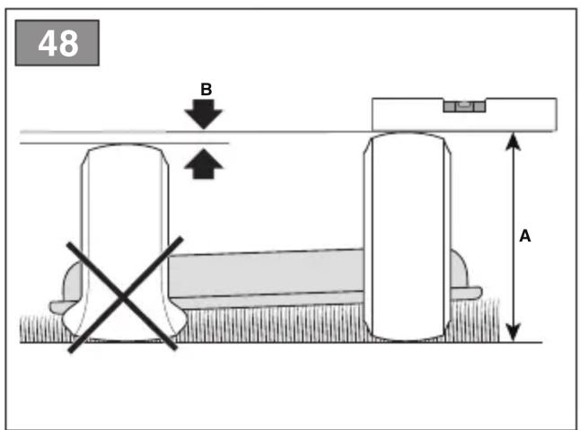
7.4 ANTI-SCALPING WHEELS
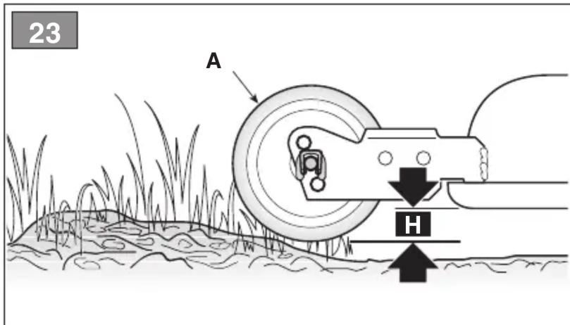
Thanks to the various mounting positions of the wheels, it is possible to maintain a safety distance “H” between the edge of the cutting device assembly and the ground (fig. 23.A). Adjust the position of the anti-scalping wheels according to how irregular the ground is.

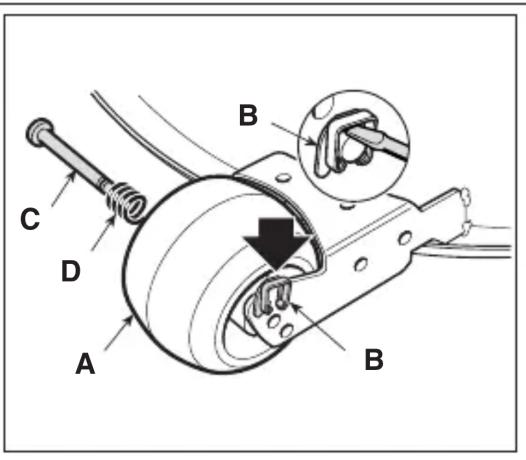
This should always be performed both wheels, positioning them at the height WITH THE ENGINE OFF CUTTING device DISENGAGED.
To change the position:
- Release the arrest plate (fig. 23.B) using a screwdriver and extract the pin (fig. 23.C) with the spring (fig. 23.D).
- Reposition the wheel (fig. 23.A) in the desired position
- Replace the pin (fig. 23.C), the spring (fig. 23.D) and the arrest plate (fig. 23.B)
in the sequence indicated, making sure that the head of the pin (fig. 23.C) is facing the inside of the machine
7.5 BATTERY
To ensure long life to the battery it is essential to keep it carefully maintained.
The machine battery must always be charged:
- before using the machine for the first time after purchase;
- before leaving the machine disused for a long period (over 30 days) (par. 9);
- before starting up the machine after a prolonged period of inactivity.
Carefully read and observe the battery recharging instructions in the booklet provided with the battery. Failure in following the procedure or in charging the battery could permanently damage the battery elements. A flat battery must be recharged as soon as possible.
IMPORTANT Recharging must be
done using a battery charger at constant voltage. Other recharging systems can irreversibly damage the battery.
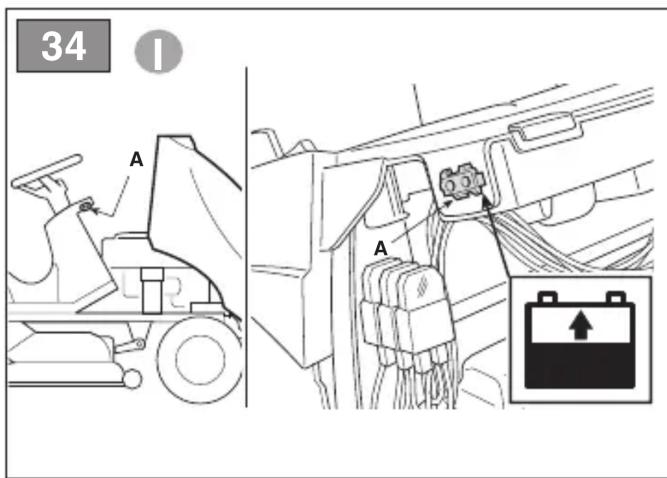
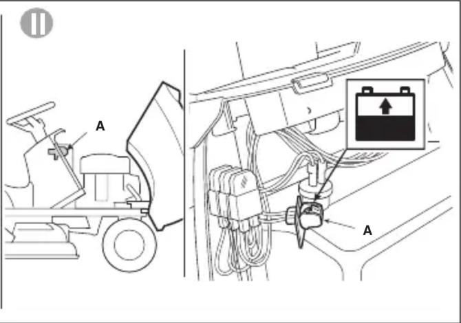
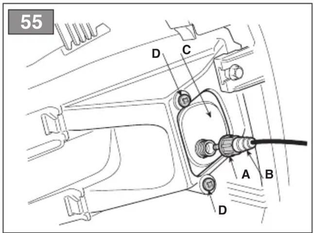
- The machine comes with a connector (fig. 34.A) for recharging; this is connected to the corresponding connector for the special maintenance battery charger supplied (if included) or available on request (par. 15.2).
IMPORTANT This connector must
only be used for connection to the maintenance battery charger indicated by the Manufacturer. For its use:
– follow the instructions given in the relative instruction manual;
– follow the instructions in the battery manual;
7.6 CLEANING
Clean thoroughly following the instructions below every time it is used.
7.6.1 Cleaning the machine
- Clean the outside of the machine washing the plastic parts of the bodywork with a damp sponge using water and detergent, taking care not to wet the engine, the electrical parts or the electronic circuit board located under the dashboard.
- To reduce fire hazards, keep the engine, silencer, battery compartment and petrol storage area free of grass, leaves, or excessive grease.
IMPORTANT Never use hose nozzles or harsh detergents for cleaning the body and engine!
7.6.2 Cleaning the discharge chute (for rear collection models only)
If the discharge chute is clogged:
- remove the grass catcher or the rear discharge guard;
- remove the grass cuttings; you can reach them from the chute discharge opening.
7.6.3 Cleaning the grass catcher (for rear collection models only)
- Empty the grass catcher
- Shake it to remove grass cuttings and soil residue
- Replace the grass catcher and clean the interior of the cutting device assembly (par. 7.6.4-a), now remove the grass catcher, empty and rinse it, then place it where it can dry quickly.
7.6.4 Cleaning the cutting device assembly
⚠️ Keep people or animals away from the surrounding area when cleaning the cutting device assembly.
a. Cleaning the interiors
Remove any traces of grass or dirt that have accumulated inside the cutting device assembly, since otherwise these may dry and harden, making it more difficult to start the device the next time.
When washing the inside of the cutting device assembly and the discharge chute, the machine must be on firm ground with:
– the grass catcher or the rear discharge guard mounted in place (for rear collection models only)
– the side discharge chute mounted (for models with side discharge only);
– the operator seated;
– the cutting device assembly in position «1»;
– the engine running
– the transmission in neutral
– the cutting device engaged
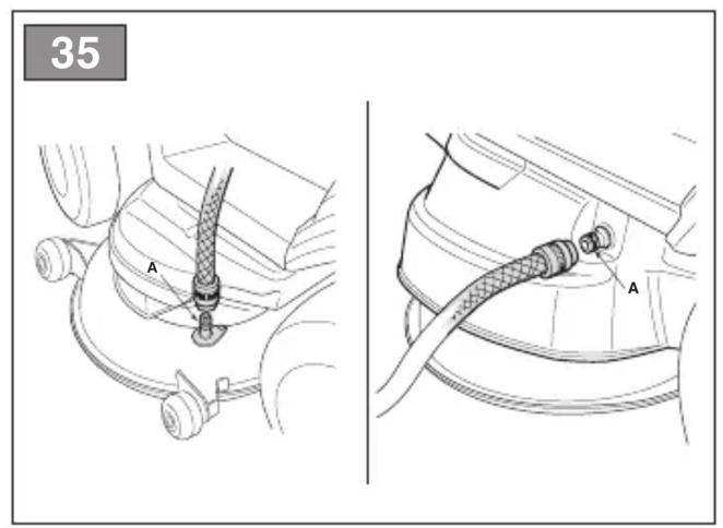
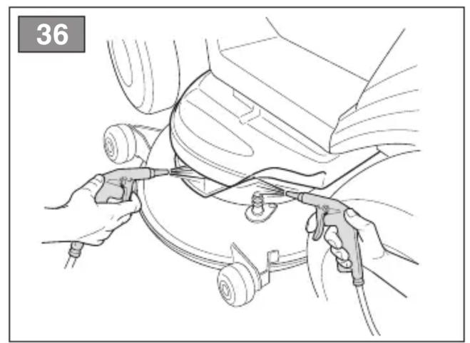
- Alternatively, connect a water tube to the dedicated coupling (fig. 35.A), allowing water to flow through each cutting device for a few minutes, while they are in motion.
IMPORTANT In order not to compromise the efficiency of the electromagnetic clutch:
- do not let the clutch come into contact with oil;
- do not spray pressurised water directly on the clutch unit;
- do not clean the clutch with petrol.
b. Cleaning the exterior
⚠ Do not let debris and dried grass accumulate in the upper part of the cutting device assembly in order to maintain maximum machine efficiency and safety levels.
To clean the upper part of the cutting device assembly:
- lower the cutting device assembly completely (position «1»);
- direct an air jet through the apertures in the left and right safety guards (fig. 36).
7.7 NUTS AND BOLTS
- Keep all nuts, bolts and screws tight to be sure the equipment is in safe working condition.
8. EXTRAORDINARY MAINTENANCE
8.1 SAFETY RECOMMENDATIONS
⚠️ You must go to a Authorised Service Centre or contact your Dealer if the following are malfunctioning:
- the brake
- the cutting device engage and disengage functions
- switching the drive to forward or reverse gears.
8.2 CUTTING DEVICE ASSEMBLY
8.2.1 Aligning the cutting device assembly
The cutting device assembly should be properly adjusted to obtain an evenly mown lawn (fig. 37). If mowing is uneven, check the tyre pressure (par. 6.1.3).
If this is not sufficient to achieve an even cut, please contact your Dealer to adjust the alignment of the cutting device assembly.
8.2.2 Cutting device
Badly sharpened cutting device pull at the grass and cause the lawn to turn yellow.
All work on the cutting device (disassembly, sharpening, balancing, repairing, reassembly and/or replacing) are demanding jobs that require special skills as well as special tools. For safety reasons, these jobs are best carried out at a Authorised Service Centre.
⚠️ Always replace damaged, bent or worn cutting device, together with their nuts and bolts, in order to ensure they remain balanced.
IMPORTANT We strongly recommend changing all the cutting device at the same time, especially in the case of uneven wear.
IMPORTANT Always use original cutting device bearing the code indicated in the "Technical Data".
Given product evolution, the cutting device listed in the "Technical Data" table may be replaced in time with others having similar interchangeable and operating safety features.
8.3 REPLACING FRONT / REAR WHEELS
8.3.1 Preparation
IMPORTANT Use a suitable lifting device, for example a scissor jack.
Before changing the wheels it is necessary to complete some preliminary operations:
- Remove all attachments.
- Position the machine on a solid and even surface that guarantees stability of the machine.
- Engage the parking brake;
- Stop the engine;
- Remove the key from the ignition;
- Position the jack in the lifting position near the wheel to be changed (par. 8.3.2; par. 8.3.3).
- Check that the jack is perfectly perpendicular to the ground.
8.3.2 Choice and positioning of the jack on the rear wheels
Position some wooden wedges (fig. 38.A) at the base of the wheel (fig. 38.B) next to the wheel to be changed (fig. 38.C).
For models with rear collection:
- The maximum possible jack height when closed is 110 mm. (fig. 39).
- Position the jack under the rear plate (fig. 40.A) at 180 mm from the side edge.
For side discharge models:
- The maximum possible jack height when closed is 110 mm. (fig. 41).
- Position the jack under the rear axle, in the point indicated in the diagram (fig. 42.A).
NOTE In this position the jack allows you to only raise the wheel to be changed.
8.3.3 Choice and positioning of the jack on the front wheels
- Position some wooden wedges (fig. 43.A) at the base of the wheel (fig. 43.B) behind the wheel to be changed (fig. 43.C).
- The maximum possible jack height when closed is 110 mm.
NOTE Select the position of the jack depending on the type of machine.
- Position the jack under the front part of the machine (fig. 44.A, 45.A, 46.A) as indicated in the figure.
NOTE The jack must be positioned under the flat part of the support (fig. 44.B, 45.B).
NOTE The jack must be positioned under the central rib of the support (fig. 46.B).
8.3.4 Changing the wheel
IMPORTANT Make certain the machine remains still and stable during the lifting process. If you notice anything out of the ordinary, lower the jack immediately, check and resolve any problems and lift the machine again.
- Slide the cover off (fig. 47.A) before raising the machine.
- Raise it enough to extract the wheel easily.
- Using a screwdriver, remove the snap ring (fig. 47.B) and the shoulder washer (fig. 47.C).
- Remove the wheel to be changed.
- Coat the axle (fig. 47.D) with lubricating grease.
- Mount the spare wheel.
- Carefully replace the shoulder washer and snap ring.
- Rest the wheel on the ground replace the cover (fig. 47.A).
IMPORTANT Check that the two rear wheels are the same height (fig. 48.A) and that the difference between the external diameters of the two wheels (fig. 48.B) is no greater than 8-10 mm. On the contrary, to avoid uneven mowing, the cutting device assembly must be aligned by an Authorised Service Centre.
8.3.5 Repairing or changing tyres
Every replacement or repair of a tyre following a puncture must be performed at a specialist tyre repair centre in accordance with the procedures for the type of tread used.
8.4 ELECTRONIC CIRCUIT BOARD
The electronic circuit board is a component fitted below the dashboard which manages all machine safety devices.
The electronic board is fitted with a self-rearming protection device that interrupts the circuit in the event of a fault on the electrical system; when this device is tripped, it stops the engine and generates an acoustic signal that can only be disabled by removing the key. The circuit is re-armed automatically after a few seconds; identify and eliminate the cause or causes of the fault in order to prevent subsequent interruptions.
IMPORTANT To avoid tripping the electronic board protection device:
- do not invert the battery terminals;
- do not operate the machine without the battery, as this would cause the battery charge regulator to function irregularly;
- take care to avoid short circuits.
8.5 REPLACING A FUSE
The machine is fitted with fuses (fig. 49.A) with different capacities and functions. Specifically:
- 10 A fuse = protects the electronic board general and power circuits, when it blows the machine stops running and the dashboard light is extinguished (par. 5.16)
- 25 A fuse = protects the battery recharge circuit. When it blows, the battery gradually runs down and the machine will have problems starting.
- 5 A fuse = protects the auxiliary 12 V power supply socket for the attachments.
- 15 A fuse = protects the command motor circuit, when it blows the electrical grass catcher bag tipping system is disabled; in this condition it is still possible to tip the bag by using the manual lever (if fitted).
The fuse capacity is indicated on the fuse.
IMPORTANT A blown fuse must always be replaced by one of the same type and amperage and never with one of another rating.
If you are unable to understand why it has blown contact Your Dealer.
8.6 REPLACING BULBS
8.6.1 Type "I" - Incandescent light bulbs
- The bulbs (18W) have a bayonet fitting and are installed in the bulb holder, which can be taken out by turning it anti-clockwise with pliers (fig. 50).
8.6.2 Type "II" - LED light bulbs
- Loosen the lock nut (fig. 51.A) and remove the connector (fig. 51.B). Remove the LED illuminator (fig. 51.C), secured by screws (fig. 51.D).
8.6.3 Type "III" - LED light bulbs (for TNS, THNS models)
- Raise the bonnet and remove the connector (fig. 52.A).
- Detach the cotter pin (fig. 52.B) and slide the bonnet off laterally.
- Detach the LED light bulb cables (fig. 53.A), undo the screws (fig. 53.B) and release the tabs (fig. 53.C).
- Raise and release the upper part of the bonnet (fig. 54.A).
- Undo the screws (fig. 55.A) and replace the LED headlights (fig. 55.B).
- To replace the bonnet, repeat the above procedure in reverse order.
8.7 REAR DRIVE UNIT
This is a sealed single unit that does not require maintenance. It is permanently lubricated and its lubricant does not need changing or topping up.
8.8 FRONT DRIVE UNIT (4WD MODEL)
This is a sealed single unit that does not require maintenance. It is necessary to check the oil in the hydraulic coupling circuit, top it up and change it at regular intervals.
Check that the oil level in the hydraulic system is between the «MIN» and «MAX» markers on the tank. If the level is below the «MIN» reference marker (Fig. 56):
– remove the guard (fig. 56.A), which is secured by the nut (fig. 56.B):
- unscrew the plug (fig. 56.C) and top up using 10W30 oil until the level reaches the «MAX» marker:
- replace the plug (fig. 56.C) and the guard (fig. 56.A).
IMPORTANT If it becomes necessary to top-up the oil level frequently, check the oil tubes and tank for leaks and contact your Dealer for the necessary maintenance.
8.9 REGULATING THE GRASS CATCHER RETAINING PAWL SPRING
If the grass catcher bag tends to jolt or open unexpectedly while driving over uneven ground, or if it is difficult to recouple the retaining pawl after emptying the bag, it may be necessary to adjust the tension on the spring (fig. 57.A). Adjust the mounting point by selecting the hole (fig. 57.B) that provides the desired result.
9. STORAGE
When you intend to put your machine away for more than 30 days:
- Wait for the engine to cool
- Disconnect the battery cables and store it in a cool and dry place.
- Empty the fuel tank (par. 7.2.2) and follow all the instructions in the engine manual.
- Clean the machine thoroughly.
- Check the machine for any damage. If necessary, contact the Authorised Service Centre.
- Store the machine:
- with the cutting device assembly lowered
- in a dry place
– protected from inclement weather
– covered with a sheet where possible (par. 15.4)
– in a place where children cannot get to it
- making sure that keys or tools used for maintenance are removed.
Before starting to use the machine again:
- check that there are no fuel leaks from the tubes, fuel stopcock or carburettor:
- prepare the machine as described in chapter "6. Using the machine".
10. HANDLING AND TRANSPORTATION
- When handling the machine, always:
– disengage the cutting device;
– bring the cutting device assembly to the highest position;
- stop the engine;
- When transporting the machine on a vehicle or trailer, always:
– use an access ramp of suitable strength, width and length;
- load the machine with the engine switched off, with the key removed from the ignition, without a driver and pushed by an adequate number of people;
– close the fuel tap (if provided);
– lower the cutting -device assembly;
- engage the parking brake;
– position it so that it does not cause a hazard to anyone;
– fasten firmly to the device of transport using ropes or chains to prevent it from tipping over causing damage and fuel leaks.
11. ASSISTANCE AND REPAIRS
This manual provides all the necessary information to run the machine and for correct basic maintenance operations which can be performed by the user. Any regulations and maintenance operations not described herein must be carried out by your Dealer or Authorised Service Centre, which have the necessary knowledge and equipment to ensure that the work is carried out correctly, maintaining the correct degree of safety and the original operating conditions of the machine. Any operations performed in unauthorised centres or by unqualified persons will totally invalidate the Warranty and all obligations and responsibilities of the Manufacturer.
- Only Authorised Service Centres can carry out guaranteed repairs and maintenance.
- Non-original parts and attachments are not approved; use of non-original spare parts and attachments will jeopardise the safety of the machine and relieve the Manufacturer from all obligations or liabilities.
• Genuine spare parts are supplied by Authorised Assistance Centres and Dealers.
- It is advisable to send your machine once a year to an Authorised Service Centre for servicing, assistance and safety device inspection.
12. WARRANTY COVERAGE
The warranty covers all material and manufacturing defects. The user must follow all the instructions provided in the accompanying documentation. The warranty does not cover damages caused by:
- Failure to become familiar with the documentation accompanying the machine.
- Carelessness.
- Incorrect or prohibited use or assembly.
- Use of non-genuine spare parts.
- Use of attachments not supplied or approved by the manufacturer.
The warranty does not cover:
- Normal wear and tear of consumables, such as drive belts, headlights, wheels, blades, safety bolts and wires.
- Normal wear and tear.
- Engines. Engines are covered by the warranty provided by the relative manufacturer in compliance with the specified terms and conditions.
The purchaser is protected by his own national legislation. The purchaser's rights envisaged by the national laws in his own country are not in any way restricted by this warranty.
13. MAINTENANCE TABLE
| Operation Interval (hours) | Paragraph | / Notes |
| First time | Subsequently every |
| MACHINE |
| Safety checks/check controls | | Before each use par. 6.2 |
| Tyre pressure check | | Before each use par. 6.1.3 |
| Check the rear/lateral discharge guards. Check the grass catcher bag and lateral discharge chute. | | Before each use par. 6.1.4 |
| General cleaning and inspection | | After each use par. 7.6 |
| Checking for any damage to the machine. If necessary, contact the Authorised Service Centre. | | After each use - | |
| Charging the battery | | Before storage | par. 7.5 |
| Complete bolt and screw check | | 25 | |
| Cutting device positioning and sharpening check | | 25 *** | |
| Transmission belt check | | 25 *** | |
| Cutting device control belt check | | 25 *** | |
| Brake regulation and check | | 25 *** | |
| Drive regulation and check | | 25 *** | |
| Cutting device gear and brake check | | 25 *** | |
| General lubrication | | 25 **** | |
| Replacing cutting device | | 100 *** | |
| Replacing the transmission belt | | - ** / *** | |
| Replacing the cutting device control belt | | - ** / *** | |
| ENGINE * |
| Checking/topping up fuel level | | Before each use par 7.2 |
| Check/top-up engine oil | | Before each use par 7.3 |
| Replacement of the engine oil | | * | * |
| Air filter cleaning and check | | * | * |
| Air filter replacement | | * | * |
| Fuel filter check | | * | * |
| Fuel filter replacement | | * | * |
| Spark plug points cleaning and check | | * | * |
| Replace the spark plug | | * | * |
| | | |
* Consult the manual supplied with the engine for a complete list of maintenance operations and the corresponding intervals
** At the first signs of any malfunction, contact your Dealer immediately
*** The operation must be carried out by your Dealer or a Authorised Service Centre
*** General lubrication of all joints should also be carried out whenever the machine is to be left unused for a long period
14. PROBLEM IDENTIFICATION
| PROBLEM PROBALE CAUSE REMEDY | |
| 1. When the key is turned to the «ON» position, the dashboard fails to switch on and there is no acoustic signal | The safety device of the electronic circuit board has cut in due to: | Turn the ignition key to «STOP» position and look for the cause of the problem: |
| badly connected battery check the connections (par. 4.4) | |
| battery terminals inverted check the connections (par. 4.4). | |
| flat battery recharge the battery (par. 7.5) | |
| fuse blown replace fuse (10 A) (par. 8.5). | |
| wet circuit board dry using lukewarm air | |
| 2. When the key is turned to the «ON» position, the dashboard fails to switch on but the acoustic signal is activated | The safety device of the electronic circuit board has cut in due to: | Turn the ignition key to «STOP» position and identify the cause of the problem: |
| wet circuit board dry using lukewarm air | |
| 3. With the key on «START» the dashboard is illuminated, but the starter motor does not run | insufficiently charged battery recharge the battery (par. 7.5) | |
| battery charger fuse blown replace fuse (25 A) (par. 8.5) | |
| 4. With the key on «START» the starter motor runs but the engine does not start | insufficiently charged battery recharge the battery (par. 7.5) | |
| faulty fuel supply check the level in the tank (par. 7.2.1) | |
| open the fuel stopcock (if foreseen) (par. 6.4) |
| check the fuel filter |
| faulty ignition check that the spark plug | cap is securely fitted |
| check that the electrodes are clean and have the correct gap |
| 5. Starting is difficult or the engine runs erratically | carburation problems | clean or replace the air filter |
| empty the fuel tank and refill with fresh fuel |
| check and replace the fuel filter if necessary |
| 6. Weak engine performance during cutting | forward speed too high in relation to cutting height | reduce the forward speed and/or raise the cutting height (par. 6.5.4) |
| 7. The engine stops when the cutting device are engaged | engage not enabled | check that all starting conditions are met (par. 6.2.2) |
| 8. The battery indicator light remains on even after the machine has been running for a few minutes | insufficient battery charge | contact your Dealer |
| 9. The oil indicator light switches on during operation (if fitted) | engine lubrication problems | Turn the key to the «STOP» position immediately: |
| top-up the oil level (see 7.3.1) |
| replace the filter (if the problem persists, contact your Dealer) |
If problems persist after having performed the above operations, contact your Dealer.
| PROBLEM PROBABLE CAUSE REMEDY | |
| 10. The engine stops running and an acoustic signal is generated | The safety device of the electronic circuit board has cut in due to: | Turn the ignition key to «STOP» position and identify the cause of the problem: |
| over-voltage caused by the charger regulator | contact your Dealer |
| battery not connected correctly (poor contacts) | check the connections (see 3.4) |
| 11. The engine stops running, and no acoustic signal is generated | battery disconnected check the connections (see 3.4) |
| engine problems contact your Dealer | |
| 12. The cutting device do not engage or do not stop promptly when they are disengaged | loose belt contact your Dealer | |
| problems with the electro-magnetic clutch | contact your Dealer |
| 13. Uneven mowing and insufficient collection (for rear collection models only) | cutting device assembly is not parallel to the ground | check the tyre pressure (par. 6.1.3) |
| reinstate the alignment of the cutting device assembly in relation to the ground (par. 8.2.1) |
| inefficient cutting device contact your Dealer |
| forward speed too high compared to height of grass | reduce the forward speed and/or raise the cutting device assembly (par. 6.5.4) |
| wait for the grass to dry |
| collector chute is blocked remove the grass catcher bag and empty the chute (see 7.6.2) |
| 14. Uneven mowing (side discharge models only) | cutting device assembly is not parallel to the ground | check the tyre pressure (par. 6.1.3) |
| reinstate the alignment of the cutting device assembly in relation to the ground (par. 8.2.1) |
| inefficient cutting device contact your Dealer |
| 15. Unusual vibrations while working | cutting device assembly is full of grass clean the cutting device assembly (par. 7.6.4) |
| the cutting device are unbalanced or loose | contact your Dealer |
| loose bolts and screws check and tighten all the engine and frame bolts |
| 16. Uncertain or ineffective braking | the brake is not adjusted correctly contact your Dealer |
| 17. Erratic forward movement, poor drive when going uphill or if the machine has a tendency to rear up | problems with the belt or the engagement device | contact your Dealer |
| 18. When the engine is running, the machine remains stationary when the drive pedal is pressed | release lever in the gear disengagement position | return it to the gear engaged position (par. 5.4) |
If problems persist after having performed the above operations, contact your Dealer.
| PROBLEM PROBABLE CAUSE REMEDY | |
| 19. Unusual machine vibrations | damaged or loose parts stop the machine and remove the ignition key |
|
|
|
|
|
If problems persist after having performed the above operations, contact your Dealer.
15. ATTACHMENTS
15.1 "MULCHING" KIT
It finely chops the grass cuttings and leaves them on the lawn (fig. 58.A1; fig 58.A2).
15.2 MAINTENANCE BATTERY CHARGER
This keeps the battery in good working order when the machine is in storage, guaranteeing an optimum level of charge and longer battery life (fig. 58.B).
15.3 TOWING KIT
To tow a small trailer (fig. 58.C).
15.4 CANVAS COVER
Protects the machine from dust when not in use (fig. 58.D)
15.5 REAR WEIGHT KIT
They improve the rear stability of the machine, especially when used mainly on sloping ground (Figure 58.E).
15.6 REAR DISCHARGE GUARD KIT
To be used in place of the grass catcher when mown grass is not collected (Fig. 58.F). (For rear discharge models only).
15.7 SNOW CHAINS 18", 20"
Improved adherence of the rear wheels on the snow-covered sections and possibility of using snow ploughs (Fig. 58.G).
15.8 MUD / SNOW WHEELS 18", 20"
Improve drive performance on snow and mud (Figure 58.H).
15.9 TRAILER
To transport tools or tall objects within permitted load limits (Fig. 58.1).
15.10 SPRINKLER
To spread salt or fertilizers (Fig. 58.J).
15.11 SPRINKLER
To spread sand or gravel (Fig. 58.K).
15.12 GRASS ROLLER
To compact the soil after sowing or to flatten grass (Fig. 58.L).
15.13 SNOW BLADE
For ploughing and accumulating removed snow at sides (Fig. 58.M).
15.14 FRONT SWEEPER
To clean leaves and dirt from paths and solid surfaces and remove thin layers of fresh snow (Fig. 58.N).
15.15 SHREDDER
Cutting and shredding rough grass (Fig. 58.O).
15.16 LEAF AND GRASS COLLECTOR
To collect leaves and grass from grassy areas (Fig. 58.P).
15.17 FRONT RAKE
To collect grass and twigs (Fig. 58.Q).
15.18 LIFTING INTERFACE
Used to mount additional front accessories that do not require using the power take-off (Fig. 58.R1).
15.19 POWER TAKE-OFF (PTO)
Used for transferring the engine power to an attachment. Lifting interface is required (Fig. 58.R2).
15.20 POWER TAKE-OFF (PTO)
Used for transferring the engine power to an attachment. Lifting interface is not required (Fig. 58.R3).
ÍNDICE
15.1 KIT PARA "MULCHING"
1.1 KUIDAS KASUTUSJUHENDIT LUGEDA
5.2 EDASIKÄIGU PEDAAL
7.4 PINNASESSE LÕIKAMIST TAKISTAVAD RATTAD
15.18 TÕSTMISE LIIDES
- Malleille TS-TX-TH
8.5 REMPLACEMENT D'UN FUSIBLE
10. MANUTENTION ET TRANSPORT
• Za modele TS-TX-TH
Montirajte košaru sukladno uputama u knjižici s uputama koja se dostavlja uz taj dio.
4.9 MONTIRANJE RUČICA ZA OKRETANJE KOŠARE ZA SAKUPLJANJE TRAVE
6.3 UPORABA NA TERENIMA S NAGIBOM
Poštujte ograničenja koja se navode u tablici "Tehnički podaci" i na sl. 24, bez obzira na smjer kretanja.
Imajte na umu da ne postoji "sigurna" padina. Kretanje po terenima s nagibom zahtijeva posebnu pozornost. Kako biste izbjegli prevrtanja ili gubitak kontrole nad strojem:
8.6 A LÁMPÁK CSERÉJE
15.20 ERÓLEADÓ (TLT)
- PLĀNOTĀ TEHNISKĀ APKOPE......20
6.3 LIETOŠANA UZ SLĪPĀM VIRSMĀM
7. PLĀNOTĀ TEHNISKĀ APKOPE
13. APKOPES DARBU TABULA
2.5 BESCHERMING VAN DE OMGEVING
5.8 SCHAKELAAR KOPLAMPEN

Controlelamp knippert: brandstof in reserve (afb. 16.D).

Controlelamp knippert: brandstof in reserve.
Controlelamp brandstof met peilmeter (afb. 16.D).
Brandstofpeil in reserve.
Brandstofpeil in reserve.
7.2.2 Lediging reservoir
7.7 MOEREN EN SCHROEVEN VOOR BEVESTIGING
8.6.1 Type "I" - Gloeilampen
15.1 KIT VOOR "MULCHING"
- GENERELT....2
- SIKKERHETSBESTEMMELSER......2
- BLI KJENT MED MASKINEN 5
- ORDINÆRT VEDLIKEHOLD 21
- EKSTRAORDINÆRT VEDLIKEHOLD ..... 24
2.4 VEDLIKEHOLD OG LAGRING
3. BLI KJENT MED MASKINEN
3.1 BESKRIVELSE AV MASKINEN OG TILSIKTET BRUK
- For modellene TS-TX-TH
5.3 PEDAL FOR RYGGING
5.10 KNAPP FOR KLIPPING I REVERS
7. ORDINÆRT VEDLIKEHOLD
7.1 GENERELT
8. EKSTRAORDINÆRT VEDLIKEHOLD
8.1 SIKKERHETSFORSKRIFTER
8.6.3 Type "III" - LED-lamper (for modellene TNS, THNS)
8.8 FREMRE TRANSMISJON (MODELL 4WD)
- TABELL FOR VEDLIKEHOLD
15.6 SETT MED VERN FOR UTKAST BAK
7.5 Akumulator....23
• Dla modeli TS-TX-TH
6.1 CZYNNOŚCI WSTĘPNE
15.1 KIT PARA "MULCHING"
4.3 MONTAREA SCAUNULUI
- Semnal acustic intermittent:
- Sacul de colectare este plin.
5.17 AFIŞAJ TIP „II" ŞI SEMNALIZĂRI ACUSTICE
- Semnal acustic intermittent:
6. UTILIZAREA MAŞINII

15.1 KIT PENTRU MULCI
15.3 SET DE TRACTARE
Pentru tractarea unei mici remorci (fig. 58.C).
15.4 PRELATĂ DE ACOPERIRE
• Pre modely TS-TX-TH
6.5 PRACOVNÁ ČINNOSŤ
6.5.1 Pohyb smerom dopredu a presuny
Počas presunu:
• Za modele TS-TX-TH
6.3 UPORABA NA NAGNJENIH TERENIH
7.5 Akumulator....22
7.6 Čišćenje 22
7.7 Matice i šrafovi za fiksiranje......23
- VANREDNO ODRŽAVANJE 23
8.1 Sigurnosne preporuke....23
8.2 Sklop reznih glava 23
8.3 Zamena prednjih / zadnjih točkova.....24
• Za modele TS-TX-TH
6.3 UPOTREBA NA STRMIM TERENIMA
Pridržavajte se ograničenja navedenih u tabeli „Tehnički podaci“ i na „sl. 24“, nezavisno od smera kretanja.
INNEHÅLLSFÖRTECKNING
- ALLMÄN INFORMATION ...... 2
- SÄKERHETSFÖRESKRIFTER 2
- LÄRA KÄNNA MASKINEN 4
15.1 SATS FÖR "MULCHING"
• TS-TX-TH modelleri
D. Lgs.262/2002, ANNEX VI, proc. 1 (Italy)
(Supply of Machinery (Safety) Regulations 2008, S.I. 2008 No. 1597, Annex II, part A)
- The company: ST. S.p.A. – Via del Lavoro, 6 – 31033 Castelfranco Veneto (TV) – Italy
- Hereby declares under its own responsibility that the machine:
Ride-on lawnmower with seated operator (grass cutting)
a) Homologation type: T•••• 92 Hydro
c) Serial number: 22A••RON000001 ÷ 99L••RON999999
d) Engine: petrol
- Conforms to UK Regulations:
• S.I. 2008/1597 - Supply of Machinery (Safety) Regulations 2008
• S.I. 2001/1701 - Schedule 9 - Noise Emission in the Environment by Equipment for use Outdoors Regulations 2001
e) Notified body: N. 0197 – TÜV Rheinland LGA Products GmbH
Tillystrasse 2, 90431 Nürnberg – Germany
• S.I. 2016/1091 - Electromagnetic Compatibility Regulations 2016
- S.I. 2012/3032 - The Restriction of the Use of Certain Hazardous Substances in Electrical and Electronic Equipment Regulations 2012
- Reference to harmonised standards:
EN ISO 5395-1:2013 + A1:2018
EN ISO 5395-3:2013 + A1:2017 + A2:2018
EN 55012:2007 + A1:2009
EN ISO 14982:2009
EN 63000:2018
g) Measured sound power level: 99 dB(A)
h) Guaranteed sound power level: 100 dB(A)
i) Cutting width: 88 cm
n) Person authorised to compile the technical file: ST. S.p.A.
Via del Lavoro, 6
31033 Castelfranco Veneto (TV) - Italia
o) Castelfranco Veneto, 01/10/2022 CEO Stiga Group
Sean Robinson

UK Importer:
STIGA LTD
Unit 8, Bluewater Estate Plympton,
Devon, PL7 4JH, England

D. Lgs.262/2002, ANNEX VI, proc. 1 (Italy)
e) Ente certificatore: N. 0197 – TÜV Rheinland LGA Products GmbH
Tillystrasse 2, 90431 Nürnberg – Germany
• EMCD: 2014/30/EU
• RoHS II: 2011/65/EU - 2015/863/EU

(Supply of Machinery (Safety) Regulations 2008, S.I. 2008 No. 1597, Annex II, part A)
- The company: ST. S.p.A. – Via del Lavoro, 6 – 31033 Castelfranco Veneto (TV) – Italy
- Hereby declares under its own responsibility that the machine:
Ride-on lawnmower with seated operator (grass cutting)
a) Homologation type: T…… 102 - T…… 102 Hydro
c) Serial number: 22A••RON000001 ÷ 99L••RON999999
d) Engine: petrol
- Conforms to UK Regulations:
• S.I. 2008/1597 - Supply of Machinery (Safety) Regulations 2008
• S.I. 2001/1701 - Schedule 9 - Noise Emission in the Environment by Equipment for use Outdoors Regulations 2001
e) Notified body: N. 0197 – TÜV Rheinland LGA Products GmbH
Tillystrasse 2, 90431 Nürnberg – Germany
• S.I. 2016/1091 - Electromagnetic Compatibility Regulations 2016
- S.I. 2012/3032 - The Restriction of the Use of Certain Hazardous Substances in Electrical and Electronic Equipment Regulations 2012
- Reference to harmonised standards:
EN ISO 5395-1:2013 + A1:2018
EN ISO 5395-3:2013 + A1:2017 + A2:2018
EN 55012:2007 + A1:2009
EN ISO 14982:2009
EN 63000:2018
g) Measured sound power level: 100 dB(A)
h) Guaranteed sound power level: 100 dB(A)
i) Cutting width: 101 cm
n) Person authorised to compile the technical file: ST. S.p.A.
Via del Lavoro, 6
31033 Castelfranco Veneto (TV) - Italia
o) Castelfranco Veneto, 01/10/2022 CEO Stiga Group
Sean Robinson

UK Importer:
STIGA LTD
Unit 8, Bluewater Estate Plympton,
Devon, PL7 4JH, England

D. Lgs.262/2002, ANNEX VI, proc. 1 (Italy)
(Supply of Machinery (Safety) Regulations 2008, S.I. 2008 No. 1597, Annex II, part A)
- The company: ST. S.p.A. – Via del Lavoro, 6 – 31033 Castelfranco Veneto (TV) – Italy
- Hereby declares under its own responsibility that the machine:
Ride-on lawnmower with seated operator (grass cutting)
a) Homologation type: T••• 108 Hydro - T••• 108 Hydro SD
c) Serial number: 22A••RON000001 ÷ 99L••RON999999
d) Engine: petrol
- Conforms to UK Regulations:
• S.I. 2008/1597 - Supply of Machinery (Safety) Regulations 2008
• S.I. 2001/1701 - Schedule 9 - Noise Emission in the Environment by Equipment for use Outdoors Regulations 2001
e) Notified body: N. 0197 – TÜV Rheinland LGA Products GmbH
Tillystrasse 2, 90431 Nürnberg – Germany
• S.I. 2016/1091 - Electromagnetic Compatibility Regulations 2016
- S.I. 2012/3032 - The Restriction of the Use of Certain Hazardous Substances in Electrical and Electronic Equipment Regulations 2012
- Reference to harmonised standards:
EN ISO 5395-1:2013 + A1:2018
EN ISO 5395-3:2013 + A1:2017 + A2:2018
EN 55012:2007 + A1:2009
EN ISO 14982:2009
EN 63000:2018
g) Measured sound power level: 100 dB(A)
h) Guaranteed sound power level: 100 dB(A)
i) Cutting width: 105 cm
n) Person authorised to compile the technical file: ST. S.p.A.
Via del Lavoro, 6
31033 Castelfranco Veneto (TV) - Italia
o) Castelfranco Veneto, 01/10/2022 CEO Stiga Group
Sean Robinson

UK Importer:
STIGA LTD
Unit 8, Bluewater Estate Plympton,
Devon, PL7 4JH, England

D. Lgs.262/2002, ANNEX VI, proc. 1 (Italy)
e) Ente certificatore: N. 0197 – TÜV Rheinland LGA Products GmbH
Tillystrasse 2, 90431 Nürnberg – Germany
• EMCD: 2014/30/EU
• RoHS II: 2011/65/EU - 2015/863/EU
(Supply of Machinery (Safety) Regulations 2008, S.I. 2008 No. 1597, Annex II, part A)
- The company: ST. S.p.A. – Via del Lavoro, 6 – 31033 Castelfranco Veneto (TV) – Italy
- Hereby declares under its own responsibility that the machine:
Ride-on lawnmower with seated operator (grass cutting)
a) Homologation type: T…… 118 Hydro SD
c) Serial number: 22A••RON000001 ÷ 99L••RON999999
d) Engine: petrol
- Conforms to UK Regulations:
• S.I. 2008/1597 - Supply of Machinery (Safety) Regulations 2008
• S.I. 2001/1701 - Schedule 9 - Noise Emission in the Environment by Equipment for use Outdoors Regulations 2001
e) Notified body: N. 0197 – TÜV Rheinland LGA Products GmbH
Tillystrasse 2, 90431 Nürnberg – Germany
• S.I. 2016/1091 - Electromagnetic Compatibility Regulations 2016
- S.I. 2012/3032 - The Restriction of the Use of Certain Hazardous Substances in Electrical and Electronic Equipment Regulations 2012
- Reference to harmonised standards:
EN ISO 5395-1:2013 + A1:2018
EN ISO 5395-3:2013 + A1:2017 + A2:2018
EN 55012:2007 + A1:2009
EN ISO 14982:2009
EN 63000:2018
g) Measured sound power level: 105 dB(A)
h) Guaranteed sound power level: 105 dB(A)
i) Cutting width: 121 cm
n) Person authorised to compile the technical file: ST. S.p.A.
ST. S.p.A.
Via del Lavoro, 6
31033 Castelfranco Veneto (TV) - Italia
o) Castelfranco Veneto, 01/10/2022 CEO Stiga Group
Sean Robinson

UK Importer:
STIGA LTD
Unit 8, Bluewater Estate Plympton,
Devon, PL7 4JH, England

D. Lgs.262/2002, ANNEX VI, proc. 1 (Italy)
e) Ente certificatore: N. 0197 – TÜV Rheinland LGA Products GmbH
Tillystrasse 2, 90431 Nürnberg – Germany
• EMCD: 2014/30/EU
• RoHS II: 2011/65/EU - 2015/863/EU
(Supply of Machinery (Safety) Regulations 2008, S.I. 2008 No. 1597, Annex II, part A)
- The company: ST. S.p.A. – Via del Lavoro, 6 – 31033 Castelfranco Veneto (TV) – Italy
- Hereby declares under its own responsibility that the machine:
Ride-on lawnmower with seated operator (grass cutting)
a) Homologation type: T…… 122 - T…… 122 Hydro
c) Serial number: 22A••RON000001 ÷ 99L••RON999999
d) Engine: petrol
- Conforms to UK Regulations:
• S.I. 2008/1597 - Supply of Machinery (Safety) Regulations 2008
• S.I. 2001/1701 - Schedule 9 - Noise Emission in the Environment by Equipment for use Outdoors Regulations 2001
e) Notified body: N. 0197 – TÜV Rheinland LGA Products GmbH
Tillystrasse 2, 90431 Nürnberg – Germany
• S.I. 2016/1091 - Electromagnetic Compatibility Regulations 2016
- S.I. 2012/3032 - The Restriction of the Use of Certain Hazardous Substances in Electrical and Electronic Equipment Regulations 2012
- Reference to harmonised standards:
EN ISO 5395-1:2013 + A1:2018
EN ISO 5395-3:2013 + A1:2017 + A2:2018
EN 55012:2007 + A1:2009
EN ISO 14982:2009
EN 63000:2018
g) Measured sound power level: 104 dB(A)
h) Guaranteed sound power level: 105 dB(A)
i) Cutting width: 121 cm
n) Person authorised to compile the technical file: ST. S.p.A.
Via del Lavoro, 6
31033 Castelfranco Veneto (TV) - Italia
o) Castelfranco Veneto, 01/10/2022 CEO Stiga Group
Sean Robinson

UK Importer:
STIGA LTD
Unit 8, Bluewater Estate Plympton,
Devon, PL7 4JH, England

| FR (Traduction de la notice originale)Déclaration CE de Conformité(Directive Machines 2006/42/CE, Annexe II, partie A)1. La Société2. Déclare sous sa propre responsabilité que la machine : Tondeuse à gazon à conducteur assis/ coupe du gazona) Type / Modèle de Basec) Série d) Moteur: moteur essence3. Est conforme aux prescriptions des directives :e) Organisme de certification4. Renvoi aux Normes harmoniséesg) Niveau de puissance sonore mesuréh) Niveau de puissance sonore garanti) Largeur de coupen) Personne habilitée à établir le Dossier Technique :o) Lieu et Date | EN (Translation of the original instruction)EC Declaration of Conformity(Machine Directive 2006/42/EC, Annex II, part A)1. The Company2. Herby declares under its own responsibility that the machine: ride-on lawnmower with seated operator/ Grass cuttinga) Type / Base Modelc) Serial numberd) Motor: petrol3. Conforms to directive specifications:e) Certifying body4. Reference to harmonised Standardsg) Sound power level measuredh) Sound power level guaranteedi) Range of cutn) Person authorised to create the Technical Folder:o) Place and Date | DE (Übersetzung der Originalbetriebsanleitung)EG-Konformitätserklärung(Maschinenrichtlinie 2006/42/EG, Anhang II, Teil A)1. Die Gesellschaft2. Erklärt auf eigene Verantwortung, dass die Maschine: Aufsitzmäher / Rasenschnitta) Typ / Basismodellc) Seriennummerd) Motor: Verbrennungsmotor3. Den Anforderungen der folgenden Richtlinien entspricht:e) Zertifizierungsstelle4. Bezugnahme auf die harmonisierten Normeng) Gemessener Schalleistungspegelh) Garantierter Schalleistungspegeli) Schnittbreiten) Zur Verfassung der technischen Unterlagen befugte Person:o) Ort und Datum |
| NL (Vertaling van de oorspronkelijke gebruiksaanwijzing)EG-verklaring van overeenstemming(Richtlijn Machines 2006/42/CE, Bijlage II, deel A)1. Het bedrijf2. Verklaart onder zijn eigen verantwoordelijkheid dat de machine: Grasmaaler met zittende bediener / grasmaaliera) Type / Basismodelc) Serienummerd) Motor: benzinemotor3. Voldoet aan de specificaties van de richtlijnen:e) Certificatie-instituut4. Verwijzing naar de Geharmoniseerde normeng) Gemeten niveau van geluidsvermogen h) Gegarandeerd niveau van geluidsvermogen i) Snijbreedten) Bevoegd persoon voor het opstellen van het Technisch Dossier o) Plaats en Datum | ES (Traducción del Manual Original)Declaración de Conformidad CE(Directiva Máquinas 2006/42/CE, Anexo II, parte A)1. La Empresa2. Declara bajo su propia responsabilidad que la máquina: Cortadora de pasto con conductor sentado/ Corte hierbaa) Tipo / Modelo Basec) Matrículad) Motor: motor de explosión3. Cumple con las especificaciones de las directivas:e) Ente certificador4. Referencia a las Normas armonizadasg) Nivel de potencia sonora medidoh) Nivel de potencia sonora garantizadoi) Amplitud de corten) Persona autorizada a realizar el Manual Técnico:o) Lugar y Fecha | PT (Tradução do manual original)Declaração CE de Conformidade(Diretiva de Máquinas 2006/42/CE, AnexoII, parte A)1. A Empresa2. Declara sob a própria responsabilidade que a máquina: Corta-relvas para operador sentado/ corte da relvaa) Tipo / Modelo Basec) Matrículad) Motor: motor a explosão3. É conforme às especificações das diretivas:e) Órgão certificador4. Referência às Normas harmonizadasg) Nivel medido de potência sonorah) Nivel garantido de potência sonorai) Amplitude de corten) Pessoa autorizada a elaborar o Caderno Técnicoo) Local e Data |
| EL (Μετάφραση του πρωτοτύπου των οδηγιών χρήσης)ΕΚ-Δήλωση συμμόρφωσης(Οδηγία Μηχανών 2006/42/CE, Παράρτημα II, μέρος A)1. Η Εταιρία2. Δηλώνει υπεύθυνα ότι η μηχανή:Χλοοκοπτικό τρακτέρ με εποχούμενο χειριστή/ κοπή της χλόηςa) Τύπος / Βασικό Μοντέλοcc) Αριθμός μητρώουd) Κινητήρας: κινητήρας εσωτερικής ανάφλεξης3. Συμμορφώνεται με τις προδιαγραφές της οδηγίας:e) Οργανισμός πιστοποίησης4. Αναφορά στους Κανονισμούς εναρμόνισηςg) Στάθμη μέτρησης ακουστικής ισχύοςh) Στάθμη εγγυημένης ακουστικής ισχύοςi) Εύρος κοπήςη) Εξουσιοδοτημένο άτομο για την κατάρτιση του Τεχνικού Φυλλαδίου:o) Τόπος και Χρόνος | TR (Orijinal Talimatlarin Tercümesi)AT Uygunluk Beyanı(2006/42/CE Makine Direktifi, Ek II, bölümA)1. Şirket2. Şahsi sorumluluğu altında aşağıdaki makinenin: Oturan sürücülü çim biçme makinesi / çim kesimi a) Tip / Standart modelc) Sicil numarasıd) Motor: patlamali motor3. Aşağıdaki direktiflerin özelliklerine uygun olduğunu beyan etmektedir:e) Sertifikalandiran kurum4. Harmonize standartlara atifg) Ölçülen ses güç seviyesih) Garanti edilen ses güç seviyesi i) Kesim genişliği n) Teknik Dosyayı oluşturmaya yetkili kişi:o) Yer ve Tarih | MK (Превод на оригиналните упатства)Декларација за усогласеност со ЕУ(Директива за машини 2006/42/CE, АнексII, дел A)1. Компанијата2. изјавува со целосна лична одговорност дека следната машина:Тревокосачка со седнат управувач / косење треваa) Тип / основен моделв) етикетг) мотор: мотор со согорување3. Усогласено со спецификациите според директивите:д) тело за сертификација4. Референци за усогласени нормативие) Акустички притисокж) измерено ниво на звучна моёностз) Ниво на гарантирана звучна моёностн) obластено лице за составување на Техничката брошурао) место и датум |
| NO (Oversettelse av orginal bruksanvisning)EF- Samsvarserklæring (Maskindirektiv 2006/42/EF, Vedlegg II, del A)1. Firmaet2. Erklærer på eget ansvar at maskinen: Sittegressklipper / gressklippinga) Type / Modellc) Serienummerd) Motor: forbrenningsmotor3. Oppfyller kravene i direktivene:e) Sertifiseringsorgan4. Henvisning til harmoniserte standarderg) Målt lydeffektniváh) Garantert lydeffektnivái) Klippebredden) Person som har fullmakt til å utferdigeteknisk dokumentasjon:o) Sted og dato | SV (Översättning av bruksanvisning i original)EG-försäkran om överensstämmelse (Maskindirektiv 2006/42//EG, bilaga II, dela)1. Företaget2. Försäkrar på eget ansvar att maskinen Åkgräsklippare / gräsklippinga) Typ / Basmodellc) Serienummerd) Motor: förbränningsmotor3. Överensstämmer med föreskrifterna i direktivete) Intygsorgan_ Anmält organ4. Referens till harmoniserade standarderg) Uppmätt ljudeffektniváh) Garanterad ljudeffektnivái) Skärbreddn) Auktoriserad person för upprättandet av den tekniska dokumentationen:o) Ort och datum | DA (Oversættelse af den originale brugsanvisning)EF-overensstemmelseserklæring (Maskindirektiv 2006/42/EF, bilag II, del A)1. Firmaet2. Erklærer på eget ansvar, at maskinen: Havetraktor/ klipning af græsseta) Type / Modelc) Serienummerd) Motor: förbrændingsmotor3. Er i overensstemmelse med specifikationerne ifølge direktiverne:e) Certificeringsorgan4. Henvisning til harmoniserede standarderg) Målt lydeffektniveauh) Garanteret lydeffektniveaui) Klippebredden) Person, der har bemyndigelse til at udarbejde det tekniske dossier:o) Sted og dato |
| FI (Alkuperäisten ohjeiden käännös)EY-VAATIMUSTENMUKAISUUSVAKUUTUS (Konedirektivi 2006/42/EY, Liite II, osa A)1. Yritys2. Vakuuttaa omalla vastuullaan, että kone: Päältäjettava ruohonleikkuri / ruohonleikkuaa) Tyyppi / Perusmallic) Sarjanumero d) Moottori : räjähdysmoottori3. On yhdenmukainen seuraavien direktiivien asettamien vaatimusten kanssa:e) Sertifointiyritys4. Viittaus harmonisoituihin standardeihing) Mitattu äänitehotasoh) Taattu äänitehotasoi) Leikkuuleveysn) Teknisten asiakirjojen laatimiseenvaltuutettu henkilö:o) Paikka ja päivämäärä | CS (Překlad původního návodu k používání)ES – Prohlášení o shodě (Směrnice o Strojních zařízeních 2006/42/ES, Příloha II, část A)1. Společnost2. Prohlašuje na vlastní odpovědnost, že stroj: Sekačka se sedící obsluhou/sekačka na trávua) Typ / Základní modelc) Výrobní číslod) Motor: spalovací motor3. Je ve shodě s nafízeními směrnic:e) Certifikační orgán4. Odkazy na Harmonizované normyg) Naměřená úroveň akustického výkonuh) Zaručená úroveň akustického výkonui) Šířka řezánín) Osoba autorizovaná pro vytvoření Technického spisu:o) Misto a Datum | PL (Tłumaczenie instrukcji oryginalnej)Deklaracja zgodności WE (Dyrektywa maszynowa 2006/42/WE, Załącznik II, część A)1. Spółka2. Oświadcza na własną odpowiedzialność, że maszyna: Kosiarka z operatorem jadącym, w pozycji siedzącej na maszynie/ cięcie trawya) Typ / Model podstawowyc) Numer seryjnýd) Silnik: silnik o zapłonie iskrowym3. Spelnia podstawowe wymogi następujących Dyrektyw:e) Jednostka certyfikująca4. Odniesienie do Norm zharmonizowanychg) Zmierzony poziom mocy akustycznejh) Gwarantowany poziom mocy akustyczneji) Szerokość cięcia n) Osoba upoważniona do zredagowania Dokumentacji technicznej:o) Miejscowość i data |
| HU (Eredeti használati utasítás fordítása)EK-megfelelőségi nyilatkozata (2006/42/EK gépirányelv, II. melléklet "A" rész)1. Alulírott Vállalat2. Felelősségének teljes tudatában kijelenti, hogy az alábbi gép: Vezetőüléses fünyírogép/ fünyírás a) Típus / Alaptípusc) Gyártási számd) Motor: robbanómotor3. Megfelel az alábbi irányelvek előírásainak:e) Tanúsító szerv4. Hivatkozás a harmonizált szabványokrag) Mért zajteljesítmény szinth) Garantált zajteljesítmény szinti) Vágási szélességn) Műszaki Dosszié szerkesztésérefelhatalmazott személy:o) Helye és ideje | RU (Перевод оригинальных инструкций)Декларация соответствия нормам EC (Директива о машинном оборудовании 2006/42/EC, Приложение II, часть A)1. Предприятие2. Заявляет под собственную ответственность, что машина: Ездовая косилка с водителем / стрижка газонаа) Тип / Базовая модельс) Паспортd) Двигатель: двигатель внутреннего сгорания3. Соответствует требованиям следующих директив:e) Сертифицирующий орган4. Ссылки на гармонизированные нормыg) Измеренный уровень звуковой мощностиh) Гарантируемый уровень звуковой мощностиi) Амплитуда кошенияn) Лицо, уполномоченное на подготовку технической документации:o) Место и дата | HR (Prijevod originalnih uputa)EK Izjava o sukladnosti (Direktiva 2006/42/EZ o strojevima, dodatak II, dio A)1. Tvrtka:2. pod vlastitom odgovornošću izjavljuje da je stroj: Sjedeća kosilica trave s operaterom/ košenje travea) Vrsta / Osnovni modelc) Matični brojd) Motor: motor s unutarnjim izgaranjem3. sukladan s temeljnim zahtjevima direktiva:e) Certifikacijsko tijelo4. Primijenjene su slijedeće harmonizirane norme:g) Izmjerena razina zvučne snageh) Zajamčena razina zvučne snagei) Širina rezanjn) Osoba ovlaštena za pravljenje Tehničke datoteke:o) Mjesto i datum |
| SL (Prevod izvirnih navodil)ES izjava o skladnosti(Direktiva 2006/42/ES), priloga II, del A)1. Družba2. pod lastno odgovornostjo izjavlja, da je stroj: Traktorska kosilnica/ košnja travea) Tip / osnovni modelc) Serijska številkad) Motor: motor z notranjim izgorevanjem3. Skladen je z določili direktiv :e) Ustanova, ki izda potrdilo4. Sklicevanje na usklajene predpiseg) Izmerjen nivo zvočne močih) Zagotovljen nivo zvočne moči) Obseg košnjen) Oseba, pooblaščena za sestavotehnične knjižice:o) Kraj in datum | BS (Prijevod originalnih uputa)EZ izjava o sukladnosti(Direktiva o mašinama 2006/42/EZ, Prilog II, deo A)1. Firma2. Daje izjavu pod vlastitom odgovornošćuda je mašina: Traktorska kosilica(traktorčić) / Košenje travea) Tip / Osnovni modelc) Serijski brojd) Motor: motor s unutrašnjim izgaranjem3. sukladna s osnovnim zahtjevimadirektive:e) Certifikaciono tijelo4. Pozivanje na uskladene normeg) Izmjereni nivo zvučne snageh) Garantovani nivo zvučne snagei) Širina košenjan) Osoba ovlaštena za izradu tehničkebrošure:o) Mjesto i datum | SK (Preklad pôvodného návodu na použitie)ES vyhlásenie o zhode(Smernica o Strojných zariadeniach2006/42/ES, Príloha II, čast' A)1. Spoločnosť2. Vyhlasuje na vlastnú zodpovednosť, žestroj: Kosačka so sediacou obsluhou/kosačka na trávua) Typ / Žákladný modelc) Výrobné číslod) Motor: spaľovací motor3. Je v zhode s nariadeniami smerníc:e) Certifikačný orgán4. Odkaz na Harmonizované normyg) Nameraná úroveň akustického výkonuh) Zaručená úroveň akustického výkonui) Širka koseniaj) Čistý inštalovaný výkonn) Osoba autorizovaná na vytvorenieTechnického spisu:o) Miesto a Dátum |
| RO (Traducerea manualului fabricantului)CE -Declaratie de Conformitate(Direktiva Mašini 2006/42/CE, Anexa II,partea A)1. Societatea2. Declară pe propria răspundere cămașina: Mašină de tuns larba cu șofer lavolan/ táiat iarbaa) Tip / Model de bazác) Număr de seried) Motor: motor cu combustie3. Este în conformitate cu specificațiiledirectivelor:e) Organism de certificare4. Referință la Standardele armonizateg) Nivel de putere sonoră măsurath) Nivel de putere sonoră garantati) Lătimea de tăieren) Persoană autorizată să întocmeascăDosarul Tehnico) Locul și Data | LT (Originalių instrukciju vertimas)EB atitikties deklaracija(Mašinų direktyva 2006/42/CE, Priedas II,dalis A)1. Bendrovė2. Prisiima atsakomybę, kad jrenginys:Balinė vejapjovė su sédinčiuoperatoriumi / žolės pjovimasa) Tipas / Bazinis Modelisc) Serijos numerisd) Variklis: vidaus degimo variklis3. Atitinka direktyvose pateiktasspecifikacijas:e) Sertifikavimo įstaiga4. Nuoroda j suderintas Normasg) Išmatuotas garso galios lygish) Užtikrinamas garso galios lygisi) Pjovimo plotisn) Autorizuotas asmuo sudaryti TechninęDokumentacija:o) Vieta ir Data | LV (Instrukciju tulkojums no originălvalodas)EK atbilstības deklarācija(Direktīva 2006/42/EK par mašinām,pielikums II, daja A)1. Uznēmums2. Uznemoties par to pilnu atbildību,pazino, ka mašina: Sěžot vadāma zālienuplaujmašina/ zāles plaušanaa) Tips / Bāzes modelisc) Sērijas numursd) Motors: iekšdedzes motors3. Atbilst šädu direktīvu prasībām:e) Sertifikācijas iestāde4. Atsauce uz harmonizētiem standartiemg) Izmēritais skaņas intensitātes līmenish) Garantētais skaņas intensitātes līmenisi) Plaušanas platumsn) Pilnvarotais darbinieks, kas sagatavojatehnisko dokumentāciju:o) Vieta un datums |
| SR (Prevod originalnih uputstval)EC deklaracija o usaglašenosti(Direktiva o mašinama 2006/42/EC, PrilogII, deo A)1. Preduzeće2. Daje izjavu pod vlastitom odgovornošćuda je mašina: Traktorska kosačica(traktorčić)/ košenje travea) Tip / Osnovni modelc) Serijski brojd) Motor: motor s unutrašnjimsagorevanjem3. u skladu s osnovnim zahtevimadirektiva:e) Sertifikaciono telo4. Pozivanje na uskladene normeg) Izmereni nivo zvučne snageh) Garantovani nivo zvučne snagei) Širina košenja......n) Osoba ovlašćena za sastavljanjetehničke brošureo) Mesto i datum | BG (Превод на оригиналните инструкции)EO декларация за съответствие(Директива Машини 2006/42/EO,Приложение II, част A)1. Дружеството2. На собствена отговорност декларира,че машината: Косачка със седналводач/ рязане на треваa) Вид / Базисен моделб) Месец / година на производствов) Сериен номер) Мотор: мотор с вътрешно горене3. Е в съответствие със спецификата надирективите:d) Сертифициращ орган4. Базирано на хармонизираните нормиж) Ниво на измерена акустична мощности) Гарантирано ниво на акустична мощностй) Широчина на косенер) Лице, упълномощено да съставиТехническата Документация:o) Място и дата | ET (Algupārase kasutusjuhendi tõlge)EÜ vastavusdeklaratsioon(Masinadirektiiv 2006/42/EÜ, Lisa II, osa A)1. Firma2. Kinnitab omal vastutusel, et masin:Istuva juhiga muruniitja / muruniitjaa) Tüüp / Põhimudelc) Matrikkeld) Mootor: Sisepõlemismootor3. Vastab direktiivide nõuetele:e) Kinnitav asutus4. Viide ühlustatud standarditeleg) Möõdetud helivõimsuse taseh) Garanteeritud helivõimsuse tasei) Lõikelaiusn) Tehnilise Lehe autoriseeritud koostaja:o) Koht ja Kuupäev |
EN • The content and images in this User Manual were produced expressly for ST. S.p.A. and are protected by copyright – any unauthorised reproduction or modification to the document, either partially or in full, is prohibited.
Type: