
MULTI V ZRUN060GSS0 - Water pump LG - Free user manual and instructions
Find the device manual for free MULTI V ZRUN060GSS0 LG in PDF.
| Product Type | Water Pump (Multi V Air Conditioning System) |
| Brand | LG |
| Model | MULTI V ZRUN060GSS0 |
| Refrigerant | R32 (flammable) |
| Leak Detector | Integrated, 10-year lifespan |
| Minimum Room Area | Depends on refrigerant charge (see manual) |
| Refrigerant Charging Method | Calculated based on pipe length and number of HR units |
| Periodic Maintenance | Cleaning heat exchangers, checking for leaks |
| Safety Instructions | Use certified personnel, avoid ignition sources |
| Safety Accessories | LG alarm kit (PLDOS), LG shut-off valve (PRHPZ0*0) |
| Natural Ventilation | Recommended if charge exceeds 15.964 kg |
| Refrigerant Recovery Procedure | Use appropriate cylinders, purge with nitrogen |
| Repairability | Sealed components, requires professional service |
| Spare Parts Available | Leak detector, shut-off valves, alarm kits |
| Standards | Comply with national gas regulations |
| Power Supply | Three-phase (see device label) |
Frequently Asked Questions - MULTI V ZRUN060GSS0 LG
User questions about MULTI V ZRUN060GSS0 LG
0 question about this device. Answer the ones you know or ask your own.
Ask a new question about this device
Download the instructions for your Water pump in PDF format for free! Find your manual MULTI V ZRUN060GSS0 - LG and take your electronic device back in hand. On this page are published all the documents necessary for the use of your device. MULTI V ZRUN060GSS0 by LG.
USER MANUAL MULTI V ZRUN060GSS0 LG
OWNER'S, INSTALLATION AND SERVICE MANUAL (FOR R32)
AIR CONDITIONER

Read this owner's manual thoroughly before operating the appliance and keep it handy for reference at all times.
ENGLISH
R32 Refrigerant
TABLE OF CONTENTS
This manual may contain images or content that may be different from the model you purchased.
This manual is subject to revision by the manufacturer.
SAFETY INSTRUCTIONS
READ ALL INSTRUCTIONS BEFORE USE ....3
Notes for Flammable Refrigerant ....3
WARNING INSTRUCTIONS ....3
Instructions for Common Product....3
Instructions for Duct Product....3
Instructions for Multi V Product....3
Instructions for Hydrokit Product ....4
CAUTION INSTRUCTIONS .... 4
Instructions for Common Product....4
Instructions for Duct Product....4
Instructions for Multi V Product....4
Safety Instructions for the Service....5
CHARGING REFRIGERANT
Minimum Floor Area 9
Flow Chart....9
How to Calculate the Maximum Amount of Refrigeration......10
ETRS Unit.... 10
Generalfallation 11
Natural Ventilation Condition 11
SAFETY INSTRUCTIONS
READ ALL INSTRUCTIONS BEFORE USE
The following safety guidelines are intended to prevent unforeseen risks or damage from unsafe or incorrect operation of the appliance.
The guidelines are separated into 'WARNING' and 'CAUTION' as described below.
Notes for Flammable Refrigerant
The following symbols are displayed on units.

This symbol indicates that this appliance uses a flammable refrigerant. If the refrigerant is leaked and exposed to an external ignition source, there is a risk of fire.

This symbol indicates that the Owner's Manual should be read carefully.

This symbol indicates that service personnel should be handling this equipment with reference to the Installation Manual.

This symbol indicates that information is available in the Owner's Manual or Installation Manual.
WARNING INSTRUCTIONS

WARNING
- To reduce the risk of explosion, fire, death, electric shock, injury or scalding to persons when using this product, follow basic precautions, including the following:
Instructions for Common Product
- Do not use means to accelerate the defrosting process or to clean, other than those recommended by the manufacturer.
- The appliance shall be stored in a room without continuously operating ignition sources.(for example: open flames, an operating gas appliance or an operating electric heater)
- The appliance shall be stored so as to prevent mechanical damage and in a well-ventilated room without continuously operating ignition sources(Example: open flames, an operating gas appliance or an operating electric heater) and have a room size as specified.
- Do not pierce or burn.
- Be aware that refrigerants may not contain an odour.
- Keep any required ventilation openings clear of obstruction.
-
Ducts connected to an appliance shall not contain a potential ignition source.
-
The non-fixed appliance shall be stored in an area where the room size corresponds to the room area as specified for operation.
- The non-fixed appliance shall be stored in a room without continuously operating open flames (for example an operating gas appliance) or other potential ignition sources.(for example an operating electric heater, hot surfaces)
- If appliances with A2L refrigerants connected via an air duct system to one or more rooms are installed in a room with an area less than Amin, that room shall be without continuously operating open flames (for example an operating gas appliance) or other potential ignition sources (for example an operating electric heater, hot surfaces). A flame-producing device may be installed in the same space if the device is provided with an effective flame arrest.
- This unit is equipped with a leak detection system for safety. For leak detection to be effective, the unit must be electrically powered at all times after installation, other than when servicing.
- This unit is equipped with electrically powered safety measures. For the safety measures to be effective, the unit must be electrically powered at all times after installation, other than when servicing.
- The refrigerant sensor has a 10-year lifespan. Once the sensor detects a leak and activates, it cannot be reused and must be replaced.
- The valve shall be located so that it can be readily accessed and operated without exposing persons to escaping refrigerant. It shall be positioned outside the occupied space where practicable, or in a ventilated enclosure, and clearly identified.
- The refrigerant detection system refrigerant sensors shall only be replaced with refrigerant sensors specified by the appliance manufacturer.
- For appliances with a leak detection system, safety shut-off valves shall not be reset until the room has been ventilated, because resetting can result in additional flammable refrigerant released into the space.
Instructions for Duct Product
- Only auxiliary devices approved by the appliance manufacturer or declared suitable with the refrigerant shall be installed in connecting ductwork.
- Auxiliary devices which may be a potential ignition source shall not be installed in the duct work. Examples of such potential ignition sources are hot surfaces with a temperature exceeding 700 °C and electric switching devices.
Instructions for Multi V Product
- Protection devices, piping and fittings shall be protected as far as possible against adverse environmental effects, for example, the danger of water collecting and freezing in relief pipes or the accumulation of dirt and debris.
-
Solenoid valves shall be correctly positioned in the piping to avoid hydraulic shock.
-
Solenoid valves shall not block in liquid refrigerant unless adequate relief is provided to the refrigerant system low pressure side.
- Field-made refrigerant joints indoors shall be tightness tested. The test method shall have a sensitivity of 5 grams per year of refrigerant or better under a pressure of at least 0.25 times the maximum allowable pressure. No leak shall be detected.
• After you check the below label attached on the outdoor unit, write down the amount of refrigerant on it.
Instructions for Hydrokit Product
- Protection devices, piping and fittings shall be protected as far as possible against adverse environmental effects, for.
- The air extraction opening from the room shall be located equal or below the refrigerant release point.
- For floor mounted units, the refrigerant release point shall be as low as practicable.
- The air extraction openings shall be located in a sufficient distance from the air intake openings to prevent re-circulation to the space.
CAUTION INSTRUCTIONS

CAUTION
- To reduce the risk of minor injury to persons, malfunction, or damage to the product or property when using this product, follow basic precautions, including the following:
Instructions for Common Product
- Any person who is involved with working on or breaking into a refrigerant circuit should hold a current valid certificate from an industry-accredited assessment authority, which authorises their competence to handle refrigerants safely in accordance with an industry recognised assessment specification.
- Servicing shall only be performed as recommended by the equipment manufacturer. Maintenance and repair requiring the assistance of other skilled personnel shall be carried out under the supervision of the person competent in the use of flammable refrigerants.
- The installation of pipe-work shall be kept to a minimum.
-
Pipe-work shall be protected from physical damage.
-
Compliance with national gas regulations shall be observed.
- Mechanical connections (mechanical connectors or flared joints) shall be accessible for maintenance purposes.
- Servicing shall be performed only as recommended by the manufacturer.
- The appliance shall be stored so as to prevent mechanical damage from occurring.
- The manufacturer should specify other potential continuously operating sources known to cause ignition of the refrigerant used.
- A brazed, welded, or mechanical connection shall be made before opening the valves to permit refrigerant to flow between the refrigerating system parts.
- When mechanical connectors are reused indoors, sealing parts shall be renewed.
- When flared joints are reused indoors, the flare part shall be re-fabricated.
- Refrigerant tubing shall be protected or enclosed to avoid damage.
- Flexible refrigerant connectors (such as connecting lines between the indoor and outdoor unit) that may be displaced during normal operations shall be protected against mechanical damage.
- Periodic(more than once/year) cleaning of the dust or salt particles stuck on the heat exchanger by using water.
- Dismantling the unit, treatment of the refrigerant oil and eventual parts should be done in accordance with local and national standards.
Instructions for Duct Product
- Connected via an air duct system to one or more rooms, the supply and return air shall be directly ducted to the space.
- Open areas such as false ceilings shall not be used as a return air duct.
Instructions for Multi V Product
- Equipment piping in the occupied space shall be installed in such a way to protect against accidental damage in operation and service.
- Precautions shall be taken to avoid excessive vibration or pulsation to refrigerating piping.
- Provision shall be made for expansion and contraction of long runs of piping.
- Piping in refrigerating systems shall be so designed and installed to minimize the likelihood hydraulic shock damaging the system.
- Steel pipes and components shall be protected against corrosion with a rustproof coating before applying any insulation.
- Flexible pipe elements shall be protected against mechanical damage, excessive stress by torsion, or other forces. They should be checked for mechanical damage annually.
- The indoor equipment and pipes shall be securely mounted and guarded such that accidental rupture of equipment cannot occur from such events as moving furniture or reconstruction activities.
Safety Instructions for the Service
Checks to the Area
- Prior to beginning work on systems containing flammable refrigerants, safety checks are necessary to ensure that the risk of ignition is minimised. For repair to the refrigerating system, the following precautions shall be complied with prior to conducting work on the system.
Work Procedure
- Work shall be undertaken under a controlled procedure so as to minimise the risk of a flammable gas or vapour being present while the work is being performed.
General Work Area
- All maintenance staff and others working in the local area shall be instructed on the nature of work being carried out. Work in confined spaces shall be avoided.
Checking for Presence of Refrigerant
- The area shall be checked with an appropriate refrigerant detector prior to and during work, to ensure the technician is aware of potentially flammable atmospheres.
- Ensure that the leak detection equipment being used is suitable for use with flammable refrigerants, i.e. non-sparking, adequately sealed or intrinsically safe.
Presence of Fire Extinguisher
- If any hot work is to be conducted on the refrigerating equipment or any associated parts, appropriate fire extinguishing equipment shall be available to hand. Have a dry powder or CO2 fire extinguisher adjacent to the charging area.
No Ignition Sources
- No person carrying out work in relation to a refrigerating system which involves exposing any pipe work shall use any sources of ignition in such a manner that it may lead to the risk of fire or explosion.
- All possible ignition sources, including cigarette smoking, should be kept sufficiently far away from the site of installation, repairing, removing and disposal, during which refrigerant can possibly be released to the surrounding space. Prior to work taking place, the area around the equipment is to be surveyed to make sure that there are no flammable hazards or ignition risks. "No Smoking" signs shall be displayed.
Ventilated Area
- Ensure that the area is in the open or that it is adequately ventilated before breaking into the system or conducting any hot work. A degree of ventilation shall continue during the period that the work is carried out. The ventilation should safely disperse any released refrigerant and preferably expel it externally into the atmosphere.
Checks to the Refrigerating Equipment
- Where electrical components are being changed, they shall be fit for the purpose and to the correct specification. At all times the manufacturer's maintenance and service guidelines shall be followed.
- If in doubt consult the manufacturer's technical department for assistance.
- The following checks shall be applied to installations using flammable refrigerants:
- The actual refrigerant charge is in accordance with the room size within which the refrigerant containing parts are installed.
- The ventilation machinery and outlets are operating adequately and are not obstructed.
- If an indirect refrigerating circuit is being used, the secondary circuit shall be checked for the presence of refrigerant.
- Marking to the equipment continues to be visible and legible. Markings and signs that are illegible shall be corrected.
- Refrigerating pipe or components are installed in a position where they are unlikely to be exposed to any substance which may corrode refrigerant containing components, unless the components are constructed of materials which are inherently resistant to being corroded or are suitably protected against being so corroded.
Checks to Electrical Devices
- Repair and maintenance to electrical components shall include initial safety checks and component inspection procedures.
- If a fault exists that could compromise safety, then no electrical supply shall be connected to the circuit until it is satisfactorily dealt with.
- If the fault cannot be corrected immediately but it is necessary to continue operation, an adequate temporary solution shall be used.
- This shall be reported to the owner of the equipment so all parties are advised.
- Initial safety checks shall include:
- Capacitors are discharged: this shall be done in a safe manner to avoid possibility of sparking.
- No live electrical components and wiring are exposed while charging, recovering or purging the system.
- Continuity of earth bonding.
Repairs to Sealed Components
- During repairs to sealed components, all electrical supplies shall be disconnected from the equipment being worked upon prior to any removal of sealed covers, etc.
- If it is absolutely necessary to have an electrical supply to equipment during servicing, then a permanently operating form of leak detection shall be located at the most critical point to warn of a potentially hazardous situation.
- Particular attention shall be paid to the following to ensure that by working on electrical components, the casing is not altered in such a way that the level of protection is affected.
- This shall include damage to cables, excessive number of connections, terminals not made to original specification, damage to seals, incorrect fitting of glands, etc.
-
Ensure that apparatus is mounted securely.
-
Ensure that seals or sealing materials have not degraded to the point that they no longer serve the purpose of preventing the ingress of flammable atmospheres.
- Replacement parts shall be in accordance with the manufacturer's specifications.
Repair to Intrinsically Safe Components
- Do not apply any permanent inductive or capacitance loads to the circuit without ensuring that this will not exceed the permissible voltage and current permitted for the equipment in use.
- Intrinsically safe components are the only types that can be worked on while live in the presence of a flammable atmosphere.
- The test apparatus shall be at the correct rating.
- Replace components only with parts specified by the manufacturer.
- Other parts may result in the ignition of refrigerant in the atmosphere from a leak.
NOTE
- The use of silicon sealant can inhibit the effectiveness of some types of leak detection equipment.
- Intrinsically safe components do not have to be isolated prior to working on them.
Cabling
- Cabling will not be subject to wear, corrosion, excessive pressure, vibration, sharp edges or any other adverse environmental effects.
- The check shall also take into account the effects of aging or continual vibration from sources such as compressors or fans.
Detection of Flammable Refrigerants
- Under no circumstances shall potential sources of ignition be used in the searching for or detection of refrigerant leaks.
- A halide torch (or any other detector using a naked flame) shall not be used.
- The following leak detection methods are deemed acceptable for all refrigerant systems.
- Electronic leak detectors may be used to detect refrigerant leaks but, in the case of flammable refrigerants, the sensitivity may not be adequate, or may need re-calibration. (Detection equipment shall be calibrated in a refrigerant-free area.)
- Ensure that the detector is not a potential source of ignition and is suitable for the refrigerant used.
- Leak detection equipment shall be set at a percentage of the LFL of the refrigerant and shall be calibrated to the refrigerant employed, and the appropriate percentage of gas (25 % maximum) is confirmed.
- Leak detection fluids are also suitable for use with most refrigerants but the use of detergents containing chlorine shall be avoided as the chlorine may react with the refrigerant and corrode the copper pipe-work.
NOTE
• Examples of leak detection fluids are
- Bubble method
- Fluorescent method agents
- If a leak is suspected, all naked flames shall be removed/extinguished.
- If a leakage of refrigerant is found which requires brazing, all of the refrigerant shall be recovered from the system, or isolated (by means of shut off valves) in a part of the system remote from the leak. Removal of refrigerant shall be according to removal and evacuation procedure.
Removal and Evacuation
- When breaking into the refrigerant circuit to make repairs – or for any other purpose – conventional procedures shall be used. However, for flammable refrigerants it is important that best practice is followed since flammability is a consideration. The following procedure shall be adhered to:
- Remove refrigerant;
- Purge the circuit with inert gas (optional for A2L);
- Evacuate (optional for A2L);
- Purge with inert gas (optional for A2L);
- Open the circuit by cutting or brazing.
- The refrigerant charge shall be recovered into the correct recovery cylinders.
- For appliances containing flammable refrigerants other than A2L refrigerants, the system shall be purged with oxygen-free nitrogen to render the appliance safe for flammable refrigerants.
- This process may need to be repeated several times.
- Compressed air or oxygen shall not be used for purging refrigerant systems.
- For appliances containing flammable refrigerants, other than A2L refrigerants, refrigerants purging shall be achieved by breaking the vacuum in the system with oxygen-free nitrogen and continuing to fill until the working pressure is achieved, then venting to atmosphere, and finally pulling down to a vacuum.
- This process shall be repeated until no refrigerant is within the system.
- When the final oxygen-free nitrogen charge is used, the system shall be vented down to atmospheric pressure to enable work to take place.
- This operation is absolutely vital if brazing operations on the pipe-work are to take place.
- Ensure that the outlet for the vacuum pump is not close to any potential ignition sources and that ventilation is available.
Charging Procedures
- In addition to conventional charging procedures, the following requirements shall be followed.
- Ensure that contamination of different refrigerants does not occur when using charging equipment. Hoses or lines shall be as short as possible to
minimise the amount of refrigerant contained in them.
- Cylinders shall be kept in an appropriate position according to the instruction.
- Ensure that the refrigerating system is earthed prior to charging the system with refrigerant.
- Label the system when charging is complete (if not already).
- Extreme care shall be taken not to overfill the refrigerating system.
- Prior to recharging the system, it shall be pressure tested with the appropriate purging gas.
- The system shall be leak-tested on completion of charging but prior to commissioning.
- A follow up leak test shall be carried out prior to leaving the site.
Recovery
- When removing refrigerant from a system, either for servicing or decommissioning, it is recommended good practice that all refrigerants are removed safely.
- When transferring refrigerant into cylinders, ensure that only appropriate refrigerant recovery cylinders are employed.
- Ensure that the correct number of cylinders for holding the total system charge are available.
- All cylinders to be used are designated for the recovered refrigerant and labelled for that refrigerant (i.e. special cylinders for the recovery of refrigerant).
- Cylinders shall be complete with pressure relief valve and associated shut-off valves in good working order. Empty recovery cylinders are evacuated and, if possible, cooled before recovery occurs.
- The recovery equipment shall be in good working order with a set of instructions concerning the equipment that is at hand and shall be suitable for the recovery of flammable refrigerants.
- In addition, a set of calibrated weighing scales shall be available and in good working order.
- Hoses shall be complete with leak-free disconnect couplings and in good condition.
- Before using the recovery machine, check that it is in satisfactory working order, has been properly maintained and that any associated electrical components are sealed to prevent ignition in the event of a refrigerant release. Consult manufacturer if in doubt.
- The recovered refrigerant shall be returned to the refrigerant supplier in the correct recovery cylinder, and the relevant Waste Transfer Note arranged.
- Do not mix refrigerants in recovery units and especially not in cylinders. If compressors or compressor oils are to be removed, ensure that they have been evacuated to an acceptable level to make certain that flammable refrigerant does not remain within the lubricant.
- The evacuation process shall be carried out prior to returning the compressor to the suppliers.
- Only electric heating to the compressor body shall be employed to accelerate this process.
- When oil is drained from a system, it shall be carried out safely.
Labelling
- Equipment shall be labelled stating that it has been decommissioned and emptied of refrigerant.
- The label shall be dated and signed.
- Ensure that there are labels on the equipment stating the equipment contains flammable refrigerant.
Decommissioning
- Before carrying out this procedure, it is essential that the technician is completely familiar with the equipment and all its detail.
- It is recommended good practice that all refrigerants are recovered safely.
- Prior to the task being carried out, an oil and refrigerant sample shall be taken in case analysis is required prior to re-use of recovered refrigerant.
- It is essential that electrical power is available before the task is commenced.
a) Become familiar with the equipment and its operation.
b) Isolate system electrically.
c) Before attempting the procedure ensure that:
- Mechanical handling equipment is available, if required, for handling refrigerant cylinders.
- All personal protective equipment is available and being used correctly.
- The recovery process is supervised at all times by a competent person.
- Recovery equipment and cylinders conform to the appropriate standards.
d) Pump down refrigerant system, if possible.
e) If a vacuum is not possible, make a manifold so that refrigerant can be removed from various parts of the system.
f) Make sure that the cylinder is situated on the scales before recovery takes place.
g) Start the recovery machine and operate in accordance with instructions.
h) Do not overfill cylinders. (No more than 80 % volume liquid charge)
i) Do not exceed the maximum working pressure of the cylinder, even temporarily.
j) When the cylinders have been filled correctly and the process completed, make sure that the cylinders and the equipment are removed from site promptly and all isolation valves on the equipment are closed off.
k) Recovered refrigerant shall not be charged into another refrigerating system unless it has been cleaned and checked.
Qualification of Workers
The manual shall contain specific information about the required qualification of the working personnel for maintenance, service and repair operations. Every working procedure that affects safety means shall only be carried out by competent persons.
Examples for such working procedures are:
- Breaking into the refrigerating circuit.
- Opening of sealed components.
-
Opening of ventilated enclosures.
-
For installations with field applied mechanical joints which are exposed in the occupied space, the instructions shall state that a sensor shall be located.
- Remote located within 2 m horizontal distance in line of sight of the unit and on a wall within the room in which the unit is installed; and
- 100 mm above the floor where h0 is not more than 300 mm from the floor; or
- 300 mm above the floor where h0 is greater than 300 mm from the floor.
CHARGING REFRIGERANT
Minimum Floor Area
All indoor units should be installed satisfying A or VA is larger than Amin
Flow Chart
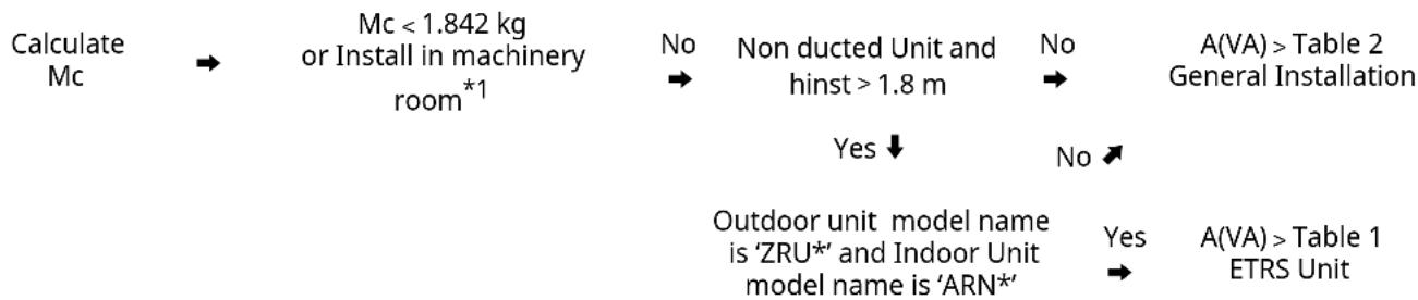
flowchart
graph TD
    A["Calculate Mc"] --> B["Mc < 1.842 kg or Install in machinery room*1"]
    B --> C["No"]
    C --> D["Non ducted Unit and hinst > 1.8 m"]
    D --> E["No"]
    E --> F["A(VA) > Table 2 General Installation"]
    C --> G["Yes ↓"]
    G --> H["Outdoor unit model name is 'ZRU*' and Indoor Unit model name is 'ARN*'"]
    H --> I["Yes"]
    I --> J["A(VA) > Table 1 ETRS Unit"]
    style A fill:#f9f,stroke:#333
    style F fill:#ccf,stroke:#333
    style J fill:#ccf,stroke:#333
*1 (ISO 5149-3:2014, Clause 5)
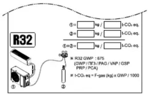
• Mc : Total amount of refrigerant in the system(kg)
• A : Floor Area (Room are where indoor unit is installed or smallest room area connected via duct system)
• VA : Ventilated Floor Area (Sum of room area connected by natural ventilation)
- Amin: Minimum Floor Area (Find in table 1 or 2)
• ETRS Unit : Enhanced Tightness Refrigerating Systems.
- hinst : Installation height. Height.
- h0 : Release height. Reference height or height of the lowest opening of the duct connection to each conditioned space
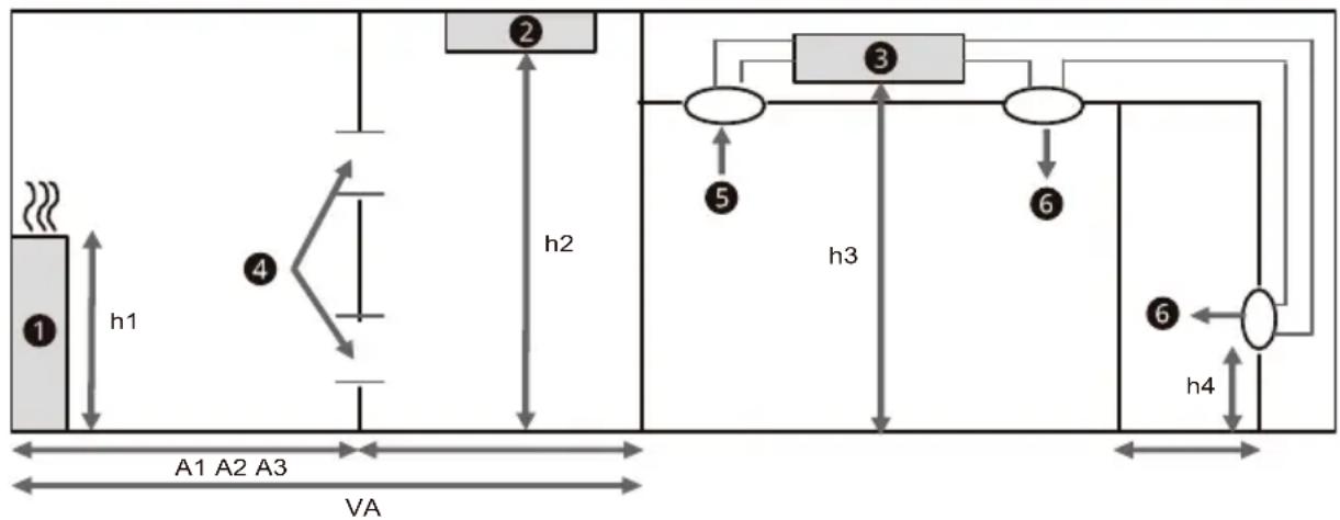
flowchart
graph TD
    A["①"] -->|h1| B["②"]
    B -->|h2| C["③"]
    C -->|h3| D["④"]
    D -->|h4| E["⑤"]
    E --> F["⑥"]
    F --> G["⑦"]
    style A fill:#f9f,stroke:#333
    style B fill:#ccf,stroke:#333
    style C fill:#cfc,stroke:#333
    style D fill:#fcc,stroke:#333
    style E fill:#cff,stroke:#333
    style F fill:#ffc,stroke:#333
    style G fill:#cfc,stroke:#333
① Indoor Unit 1 : hinst=0, h0=h1, A=A1, VA=A1+A2 (if natural ventilation condition is satisfied)
2 Indoor Unit 2 : hinst=h2, h0=h2,A=A2, VA=A1+A2 (if natural ventilation condition is satisfied)
③ Indoømit 3: hinst=h3, h0=h4, A=A3
4 Natural Ventilation Opening
5 Return Opening
6 Supply Opening
How to Calculate the Maximum Amount of Refrigerant
When installing the appliance, the amount of additional refrigerant charged must be considered the pipe diameter, length and the amount of refrigerant that can be charged in indoor unit.
Amount of additional refrigerant (kg)
= Total Pipe Length (m): ∅ 22.20 mm X 0.313 kg/m (R32)
+ Total Pipe Length (m): ∅ 19.05 mm X 0.235 kg/m (R32)
+ Total Pipe Length (m): ∅ 15.88 mm X 0.153 kg/m (R32)
+ Total Pipe Length (m): ∅ 12.70 mm X 0.103 kg/m (R32)
+ Total Pipe Length (m): ∅ 9.52 mm X 0.053 kg/m (R32)
+ Total Pipe Length (m): ∅ 6.35 mm X 0.019 kg/m (R32)
+ Number of installed HR Unit(2, 3, 4port) X 0.45 kg (R32)
+ Number of installed HR Unit(6, 8port) X 0.9 kg (R32)
+ Amount of Additional Refrigerant for Indoor Unit ^*1
*1 Please refer to the paper sheet named as Additional Refrigerant table of IDU. It is provided in the outdoor unit.
ETRS Unit
To install indopunit, some safety measures may be needed depend on area or ventilated floor area (when natural ventilation used). Maximum charge of the system is 15.964 kg x number of indoor units in the system, not exceed 63.856 kg. Safety measures are LG alarm kit(PLDCAA0S), LG Shut off valve(PRHPZ0*0), and natural ventilation. For more detail for LG accessories(alarm kit, shut off vale), see accessories manual.
Graph and table is based on room height 1.8m. If it is higher(max 2.2m), smaller minimum floor area can be applied.
Minimum Floor Area of Lowest Underground Floor
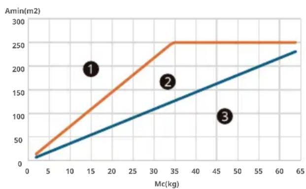
line
| Mc(kg) | Amin(m2) | | ------ | -------- | | 15 | 200 | | 35 | 250 | | 47 | 250 |① No safety measure is needed
② Two safety measures
③Cannot be installed
Minimum Floor Area of Other Floors
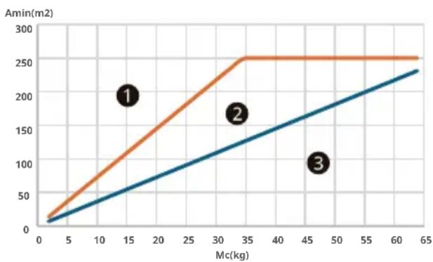
line
| Mc(kg) | Amin(m2) | | ------ | -------- | | 15 | 200 | | 35 | 250 | | 45 | 100 |① No safety device is needed
②One safety measures
③ Two safety measures
General Installation
To install indoor unit, some safety device may be needed depend on area or ventilated floor area (when natural ventilation used). IMc is larger than 15.964kg, natural ventilation must be installed.
Graph and table is based on minimum installation height of indoor units. If it is higher, larger minimum floor area can be applied. h0 is differed by model type.
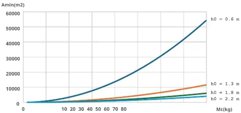
• Ceiling Suspended, Wall Mounted : 2.2
• Cassette, Floor Standing(PT, PF) : 1.8
• Hydrokit(Wall Mounted) : 1.3
• Hydrokit(Floor Standing), Floor Standing(Others) : 0.6
- Duct: Height of lowest opening of the duct connection to each conditioned space
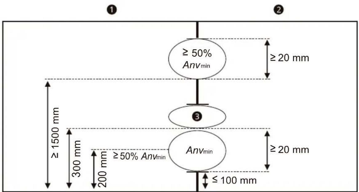
Natural Ventilation Condition
If natural ventilation is installed satisfying conditions below, "A" can be replaced with "VA". For ETRS Unit, if it is used as a safety measure, "A" cannot be replaced with "VA".
- For the Lower Opening:
- It is not an opening to the outside
- The opening cannot be closed
- The opening must be ≥ Anvmin
- The area of any openings above 300 mm from the floor does not count when determining Anvmin
- At least 50% of Anvmin is less than 200 mm above the floor
- The bottom of the lower opening is ≤100 mm from the floor
- The height of the opening is ≥20 mm
- For the upper opening:
- It is not an opening to the outside
- The opening cannot be closed
- The opening must be ≥ 50% of Anvmin
- The bottom of the upper opening must be ≥ 1500 mm above the floor
- The height of the opening is ≥ 20 mm
flowchart
graph TD
    A["≥ 50% Anv_min"] --> B["≥ 20 mm"]
    B --> C["3"]
    C --> D["≥ 20 mm"]
    D --> E["Anv_min"]
    style A fill:#f9f,stroke:#333
    style B fill:#ccf,stroke:#333
    style C fill:#cfc,stroke:#333
    style D fill:#fcc,stroke:#333
    note1["≥ 1500 mm"] --> A
    note2["≥ 100 mm"] --> D
    note3["300 mm"] --> A
    note4["200 mm"] --> C
    note5["≥ 50% Anv_min"] --> D
① Room 1
② Room 2
③ Not Count
• Minimum opening area (Anv)
$$ A n v _ {\min} = \frac {m _ {c} - m _ {\max}}{L F L \times 1 0 4} \times \sqrt {\frac {A}{g \times m _ {\max}} \frac {M}{M - 2 9}} $$
g Is the gravity acceleration of 9,81 m/s ^4 ;
29 Is the average molar mass of air in kg/kmol.
Anv Is the minimum opening for natural ventilation in m^2 .
For ETRS unit, Anv_min = 0.013 m^2
mc Is the actual refrigerant charge of refrigerant in the system in kg;
m_max Is the allowable maximum refrigerant charge in the system in kg, Calculated according to Equation below 15.964 kg.
$$ m _ {\max} = 2. 5 \times (\mathrm{LFL}) ^ {(5 / 4)} \times h _ {0} \times (\mathrm{A}) ^ {(1 / 2)} $$
Not to exceed below
$$ m _ {\max} = 0. 7 5 \times L F L \times h _ {0} \times A $$
LFL Is the lower flammability lim it in kg/m ^3 ;
A Is the room area in m^2 ;
M Is the molar mass of the refrigerant in kg/kmol;
MANUALE D'USO, INSTALLAZIONE E ASSISTENZA (PER R32)
CLIMATIZZATORE

INSTRUCTIONS D'ATTENTION ....4
INSTRUCTIONS D'ATTENTION

ATTENTION
WAARSCHUWINGSINSTRUCTIES 3
WAARSCHUWINGSINSTRUCTIES

WAARSCHUWING
Agent frigorific R32
BEZBEDNOSNA UPUTSTVA
PROČITAJTE CELO UPUTSTVO PRE UPOTREBE....3
Napomene za zapaljivo rashladno sredstvo....3
UPOZORENJE 3
BEZBEDNOSNA UPUTSTVA
PROČITAJTE CELO UPUTSTVO PRE UPOTREBE
INNEHÅLLSFÖRTECKNING
UPUTSTVO UPOZORENJA ....3
Uputstva za uobičajeni proizvod....3
Uputstvo za proizvod s kanalima ....3
Uputstvo za proizvod Multi V....3
Uputstvo za proizvod Hydrokit....4
UPUTSTVA OPREZA 4
Uputstva za uobičajeni proizvod ....4
Uputstvo za proizvod s kanalima ....4
Uputstvo za proizvod Multi V....4
Üldise toote juhised ....3
Torustikuga toote juhised....3
Multi V toote juhised....3
Hydrokit toote juhised....4
ETTEVAATUSE JUHISED 4
Üldise toote juhised 4
Torustikuga toote juhised....4
Multi V toote juhised....4
Üldise toote juhised
Multi V toote juhised
Hydrokit toote juhised
Üldise toote juhised
Multi V toote juhised
ISHLATISHDAN AVVAL BARCHA YO'RIQLARNI O'QIB CHIQING ......3
Yonuvchan sovutish vositasi uchun eslatmalar ....3