
GBG 6 Professional - Sander BOSCH - Free user manual and instructions
Find the device manual for free GBG 6 Professional BOSCH in PDF.
| Product Type | Bench Grinder |
| Brand | Bosch |
| Model | GBG 6 Professional |
| Rated Power Input | 350 W |
| Useful Power Output (50 Hz) | 240 W |
| No-load Speed (50 Hz) | 2900 rpm |
| Grinding Wheel Diameter | 150 mm |
| Grinding Wheel Width | 20 mm |
| Grinding Wheel Bore | 20 mm |
| Spindle Thread | M12 |
| Weight according to EPTA | 10.0 kg |
| Protection Class | I |
| Operating Mode | S2 (60 min) |
| Main Functions | Sharpening, sanding, deburring of metals |
| Spark Protection | Yes, included |
| Workpiece Support | Yes, adjustable |
| Maintenance and Cleaning | Unplug before cleaning; keep ventilation slots clean |
| Safety | Safety goggles mandatory; hearing protection; dust mask |
| Spare Parts and Repairability | Parts available via Bosch customer service; repair by authorized professional |
Frequently Asked Questions - GBG 6 Professional BOSCH
User questions about GBG 6 Professional BOSCH
0 question about this device. Answer the ones you know or ask your own.
Ask a new question about this device
Download the instructions for your Sander in PDF format for free! Find your manual GBG 6 Professional - BOSCH and take your electronic device back in hand. On this page are published all the documents necessary for the use of your device. GBG 6 Professional by BOSCH.
USER MANUAL GBG 6 Professional BOSCH
OBI_BUCH-1501-005.book Page 1 Tuesday, August 16, 2016 10:05 AM
Robert Bosch Power Tools GmbH
70538 Stuttgart
SIGNATURE
www.bosch-pt.com
160992A 2H2(2014.10)PS/160 EURO

GBG Professional
6|8

BOSCH
sv Bruksanwinning I original
no Original driftsinstraks
ft Alkuperaiset oheet
elnowruruaobprw yphonc
tr Original isobme talimata
pl Instrucklaoryginaln
csPovodni nivod kouzvini
sk Povodny nivod na peuditie
hu Erodete haszmalatiutasitas
OpHnHoe pKaBqCTaNo
CHUYIYIYI
uk Operinana incrypuiws
0
kknnnne
TYHNSK
mkOpmmnoynactoeabeora
sr Originalnoupstwzarad
slzyimnaewodila
hr Originae upute zaraad
et Alguparane kasutusjubond
Instrukcijas originala
It Original instruktija
ar aLst JauuU
f


Deutsch. 6
English . Page 11
Francais 16
Espanol. Pagsina 21
Portugues Pagina 27
Italiano 32
Nederlands.. 37
Dansk Side 42
Svenska Sida 47
Norsk. Side 51
Suomi . Sivu 56
EAAyivka 60
Türkce. Sayfa 65
Polski Strona 71
Cesky Strana 76
Slovensky Strana 81
Magyar Oldal 86
Pycckn 91
YkpaiHcbKa CtopiHa 98
Kaakua. 5er 103
Romana. . 109
Былгарск... .. 114
MaKeEOHcKn CtpaHa 119
Srpski Strana 125
Slovensko Stran 129
Executive Vice President Engineering
Helmut Heinzelmann
Head of Product Certification PT/ETM9


Robert Bosch Power Tools GmbH
70538 Stuttgart, GERMANY
Stuttgart, 01.01.2017
Deutsch|9
Technische Daten
General Power Tool SafetyWarnings
IMPORTANT
When using electric tools basic safety precautions should always be followed
to reduce the risk of fire, electric shock and personal injury including the following.
Read all these instructions before attempting to operate this product and save these instructions.
The term "power tool" in the warnings refers to your mains-operated (corded) power tool or battery-operated (cordless) power tool.
Work area safety
- Keep work area clean and well lit. Cluttered or dark areas invite accidents.
Do not operate power tools in explosive atmospheres, such as in the presence of flammable liquids, gases or dust. Power tools create sparks which may ignite the dust or fumes. - Keep children and bystanders away while operating a power tool. Distractions can cause you to lose control.
Electrical safety
Power tool plugs must match the outlet. Never modify the plug in any way. Do not use any adapter plugs with earthed (grounded) power tools. Unmodified plugs and matching outlets will reduce risk of electric shock.
- Avoid body contact with earthed or grounded surfaces, such as pipes, radiators, ranges and refrigerators. There is an increased risk of electric shock if your body is earthed or grounded.
Do not expose power tools to rain or wet conditions. Water entering a power tool will increase the risk of electric shock.
Do not abuse the cord. Never use the cord for carrying, pulling or unplugging the power tool. Keep cord away from heat, oil, sharp edges and moving parts. Damaged or entangled cords increase the risk of electric shock.
When operating a power tool outdoors, use an extension cord suitable for outdoor use. Use of a cord suitable for outdoor use reduces the risk of electric shock.
If operating a power tool in a damp location is unavoidable, use a residual current device (RCD) protected supply. Use of an RCD reduces the risk of electric shock.
Personal safety
Stay alert, watch what you are doing and use common sense when operating a power tool. Do not use a power tool while you are tired or under the influence of drugs, alcohol or medication. A moment of inattention while operating power tools may result in serious personal injury.
Use personal protective equipment. Always wear eye protection. Protective equipment such as dust mask, non-skid safety shoes, hard hat, or hearing protection used for appropriate conditions will reduce personal injuries.
Prevent unintentional starting. Ensure the switch is in the off-position before connecting to power source and/or battery pack, picking up or carrying the tool. Carrying power tools with your finger on the switch or energising power tools that have the switch on invites accidents.
Remove any adjusting key or wrench before turning the power tool on. A wrench or a key left attached to a rotating part of the power tool may result in personal injury.
Do not overreach. Keep proper footing and balance at all times. This enables better control of the power tool in unexpected situations.
Dress properly. Do not wear loose clothing or jewellery. Keep your hair, clothing and gloves away from moving parts. Loose clothes, jewellery or long hair can be caught in moving parts.
If devices are provided for the connection of dust extraction and collection facilities, ensure these are connected and properly used. Use of dust collection can reduce dust-related hazards.
Power tool use and care
Do not force the power tool. Use the correct power tool for your application. The correct power tool will do the job better and safer at the rate for which it was designed.
Do not use the power tool if the switch does not turn it on and off. Any power tool that cannot be controlled with the switch is dangerous and must be repaired.


12 | English
- Disconnect the plug from the power source and/or the battery pack from the power tool before making any adjustments, changing accessories, or storing power tools. Such preventive safety measures reduce the risk of starting the power tool accidentally.
- Store idle power tools out of the reach of children and do not allow persons unfamiliar with the power tool or these instructions to operate the power tool. Power tools are dangerous in the hands of untrained users.
- Maintain power tools. Check for misalignment or binding of moving parts, breakage of parts and any other condition that may affect the power tool's operation. If damaged, have the power tool repaired before use. Many accidents are caused by poorly maintained power tools.
- Keep cutting tools sharp and clean. Properly maintained cutting tools with sharp cutting edges are less likely to bind and are easier to control.
- Use the power tool, accessories and tool bits etc. in accordance with these instructions, taking into account the working conditions and the work to be performed. Use of the power tool for operations different from those intended could result in a hazardous situation.
Service
Have your power tool serviced by a qualified repair person using only identical replacement parts. This will ensure that the safety of the power tool is maintained.
SafetyWarnings for Bench Grinders

Wear safety goggles.
- Store the machine in a safe manner when not being used. The storage location must be dry and lockable. This prevents the machine from storage damage, and from being operated by untrained persons.
- Never use the machine with a damaged cable. Do not touch the damaged cable and pull the mains plug when the cable is damaged while working. Damaged cables increase the risk of an electric shock.
Check the cable regularly and have a damaged cable repaired only through an authorised customer service agent for Bosch power tools. Replace damaged extension cables. This will ensure that the safety of the power tool is maintained. - Keep handles dry, clean, and free from oil and grease. Greasy, oily handles are slippery causing loss of control.
Connect the machine to a mains supply with proper earthing connection. Socket outlet and extension cable must be equipped with an operative protective conductor. - Do not use accessories which are not specifically designed and recommended by the tool manufacturer. Just because the accessory can be attached to your power tool, it does not assure safe operation.
The rated speed of the accessory must be at least equal to the maximum speed marked on the power tool. Accessories running faster than their rated speed can break and fly apart.
Do not use a damaged accessory. Before each use, check the grinding wheel for chips and cracks. If the machine or application tool is dropped, inspect for damage or install an undamaged application tool. After inspecting and installing the application tool, position yourself and bystanders away from the plane of the rotating application tool and run the power tool at maximum no-load speed for one minute. Damaged application tools will normally break apart during this test time.
Use the machine only with the spark guard 10. Sparks being expelled can injure your eyes or set objects in the vicinity on fire.
When grinding, tilt down the spark guard 10 as far as possible. Sparking occurs when grinding metal.
Regularly check the clearance between the workpiece support 11 as well as the holder of the spark guard 9 to the grinding wheel, and readjust as required. The clearance to the grinding wheel may not exceed 2mm . When the clearance is larger, you are not sufficiently protected against sparking. The workpiece can be drawn in by the rotational motion of the grinding wheel and lead to injuries.
Guide the workpiece only against the switched-on machine and do not switch the machine off until after having removed the workpiece. The workpiece can move suddenly.
- Never apply the workpiece laterally against the rotating grinding wheel, and always grind from the front. The workpiece can be drawn out of your hand through the rotational motion of the grinding wheel and lead to injuries.
Never reach into the running grinding wheel of the machine. This can lead to serious injuries.
Do not stop coasting grinding wheels by applying lateral pressure to them. The workpiece can be drawn out of your hand through the rotational motion of the grinding wheel and lead to injuries.
Wear a work apron. Pay attention that other persons are not put at risk from sparking. Remove flammable materials in close vicinity. Sparking occurs when cutting metal.
- Keep your workplace clean. Blends of materials are particularly dangerous. Dust from light alloys can burn or explode.
Products sold in GB only: Your product is fitted with a BS 1363/A approved electric plug with internal fuse (ASTA approved to BS 1362).
If the plug is not suitable for your socket outlets, it should be cut off and an appropriate plug fitted in its place by an authorised customer service agent. The replacement plug should have the same fuse rating as the original plug.
The severed plug must be disposed of to avoid a possible shock hazard and should never be inserted into a mains socket elsewhere.
Products sold in AUS and NZ only: Use a residual current device (RCD) with a rated residual current of 30mA or less.
Symbols
The following symbols can be important for the operation of your power tool. Please memorise the symbols and their meanings. The correct interpretation of the symbols helps you operate the power tool better and more secure.
Symbols and their meaning

Keep your hands out of the grinding wheel area while the machine is running. Danger of injury in case of contact with the grinding wheel.

Wear ear protectors. Exposure to noise can cause hearing loss.

Wear safety goggles.
Wear a dust respirator.
Wear protective gloves.
Product Description and Specifications

Read all safety warnings and all instructions. Failure to follow the warnings and instructions may result in electric shock, fire and/or serious injury.
While reading the operating instructions, unfold the graphics page for the machine and leave it open.
Intended Use
The machine is intended for sharpening tools as well as for grinding and deburring metal.
The machine may only be used for short-time operation (60 min. max).
Technical Data
Double bench grinder GBG 6 GBG 8
Article number
3601B7A0..3601B7A1..
The values given are valid for a nominal voltage [U] of 230 V. For different voltages and models for specific countries, these values can vary.
*The operating mode S2 (60 min.) designates short-time operation with a maximum operating duration of 60 minutes. After this period, switch off the machine and allow it to cool down.
Bosch Power Tools 1609 92A 2H2| (17.8.16)


14|English
| Double bench grinder | GBG 6 | GBG 8 | |
| Rated power inputP1 | W | 3 | 5 |
| Output power P2 | |||
| -50 Hz | W | 240 | 420 |
| -60 Hz | W | 250 | - |
| Operating Mode* | S2 (60 min.) | S2 (60 min.) | |
| No-load speed | |||
| -50 Hz | min-1 | 2900 | 2900 |
| -60 Hz | min-1 | 3500 | - |
| Thread of grinder spindle | M 12 M 12 | ||
| Grinding wheels | |||
| -Diameter | mm | 150 | 200 |
| -Width | mm | 20 | 25 |
| -Mounting bore | mm | 20 | 32 |
| -Graɪn size | 24/60 | 24/60 | |
| Mounting flange | |||
| -Mounting bore | mm | 12.7 | 15 |
| -min.recess | mm | 1.5 | 1.5 |
| Weight according to EPTA-Procedure 01:2014 | kg 10.0 16.5 | ||
| Protection class | ±/I | ±/I | |
The values given are valid for a nominal voltage [U] of 230 V. For different voltages and models for specific countries, these values can vary.
The operating mode S2 (60 min.) designates short-time operation with a maximum operating duration of 60 minutes. After this period, switch off the machine and allow it to cool down.

Assembly
Before any work on the machine itself, pull the mains plug.
- Use suitable screws to fix the power tool to the workbench/ worktop at the 4 holes 7 provided.
Mounting the Spark Guard/Workpiece Support (see figures A-D)
Use the machine only with the spark guard 10. Sparks being expelled can injure your eyes or set objects in the vicinity on fire.
- Mount the holder for the spark guard 9 with the two screws.
- Screw the spark guard 10 to the holder of the spark guard 9.
- Mount the workpiece support 11 as shown in the figure.
Do not interchange the right and left workpiece support 11. Otherwise, the clearance between workpiece support 11 and grinding wheel will be too large. When the clearance is larger, you are not sufficiently protected against sparking. The workpiece can be drawn in by the rotational motion of the grinding wheel and lead to injuries.
Regularly check the clearance between the workpiece support 11 as well as the holder of the spark guard 9 to the grinding wheel, and readjust as required. The clearance to the grinding wheel may not exceed 2mm . When the clearance is larger, you are not sufficiently protected against sparking. The workpiece can be drawn in by the rotational motion of the grinding wheel and lead to injuries.
Replace the grinding wheel when the holder of the spark guard 9 can no longer be adjusted to the required clearance of 2mm (max.) to the grinding wheel.
Changing a Grinding Wheel
Before any work on the machine itself, pull the mains plug.
The rated speed of the accessory must be at least equal to the maximum speed marked on the power tool. Accessories running faster than their rated speed can break and fly apart.
Replace the grinding wheel as soon as its residual material reaches a thickness of 10mm
- Loosen the 3 screws of cover 1 and remove cover 1. Hold the grinding wheel wearing protective gloves and unscrew the clamping nut 2 from the grinder spindle 5.
Note: The grinder spindle 5 on the left side of the machine has a left-hand thread.
- Remove the clamping flange 3 and the grinding wheel from the grinder spindle 5.
- The new grinding wheel is mounted in reverse order. Place the cover 1 firmly onto the housing and tighten with the 3 screws.
Dress used and out-of-centre grinding wheels with a whetstone (accessory) before continuing to use them.
Dust/Chip Extraction
Dusts from materials such as lead-containing coatings, some wood types, minerals and metal can be harmful to one's health. Touching or breathing-in the dusts can cause
allergic reactions and/or lead to respiratory infections of the user or bystanders.
Certain dusts, such as oak or beech dust, are considered as carcinogenic, especially in connection with wood-treatment additives (chromate, wood preservative). Materials containing asbestos may only be worked by specialists.
- Provide for good ventilation of the working place.
- It is recommended to wear a P2 filter-class respirator.
Observe the relevant regulations in your country for the materials to be worked.
Prevent dust accumulation at the workplace. Dusts can easily ignite.
Operation
Starting Operation
Observe correct mains voltage! The voltage of the power source must agree with the voltage specified on the nameplate of the machine. Power tools marked with 230V can also be operated with 220V .
Check the grinding tools before using. The grinding tools must be properly mounted and must rotate freely. Carry out a 1 minute (minimum) test run at maximum speed in a safe environment with no load. Do not use damaged, out-of-centre or vibrating grinding tools. Damaged grinding tools can burst and cause injuries.
Switching On and Off
To save energy, only switch the power tool on when using it.
- To start the machine, push the On/Off switch 8 to the "I" position.
- To switch off the machine, push the On/Off switch 8 to the "0" position.
Working Advice
Use silicon carbide grinding discs C (accessory) when working carbide (TC) workpieces.
Protect the grinding tool against impact, shock and grease.
- Place the workpiece subject to grinding onto the workpiece support 11 and press it moderately against the grinding wheel. To achieve optimal grinding results, lightly move the workpiece back and forth. This also ensures that the grinding wheel is worn off evenly.
Occasionally cool off the workpiece in water.
Maintenance and Service
Maintenance and Cleaning
Before any work on the machine itself, pull the mains plug.
For safe and proper working, always keep the machine and ventilation slots clean.
If the replacement of the supply cord is necessary, this has to be done by Bosch or an authorized Bosch service agent in order to avoid a safety hazard.
After-sales Service and Application Service
In all correspondence and spare parts order, please always include the 10-digit article number given on the type plate of the machine.
Our after-sales service responds to your questions concerning maintenance and repair of your product as well as spare parts. Exploded views and information on spare parts can also be found under:
www.bosch-pt.com
Bosch's application service team will gladly answer questions concerning our products and their accessories.
Great Britain
Robert Bosch Ltd. (B.S.C.)
P.O.Box 98
Broadwater Park
North Orbital Road
Denham
Uxbridge
UB95HJ
At www.bosch-pt.co.uk you can order spare parts or arrange the collection of a product in need of servicing or repair.
Tel. Service: (0844) 7360109
E-Mail: boschservicecentre@bosch.com
Ireland
Origo Ltd.
Unit 23 Magna Drive
Magna Business Park
City West
Dublin 24
Tel. Service: (01) 4666700
Fax: (01) 4666888
Australia, New Zealand and Pacific Islands
Robert Bosch Australia Pty. Ltd.
Power Tools
Locked Bag 66
Clayton South VIC 3169
Customer Contact Center
Inside Australia:
Phone: (01300) 307044
Fax: (01300) 307045
Inside New Zealand
Phone: (0800) 543353
Fax: (0800) 428570
Outside AU and NZ:
Phone: +61 395415555
www.bosch.com.au
Republic of South Africa
Customer service
Hotline: (011) 6519600
Gauteng - BSC Service Centre
35 Roper Street, New Centre
Johannesburg
Tel.: (011) 4939375
Fax: (011) 4930126
E-Mail: bsctools@icon.co.za
16 | Français
KZN - BSC Service Centre
Unit E, Almar Centre
143 Crompton Street
Pinetown
Tel.: (031) 7012120
Fax: (031) 7012446
E-Mail: bsc.dur@za.bosch.com
Western Cape - BSC Service Centre
Democracy Way, Prosperity Park
Milnerton
Tel.: (021) 5512577
Fax: (021) 5513223
E-Mail: bsc@zsd.co.za
Bosch Headquarters
Midrand, Gauteng
Tel.: (011) 6519
Fax: (011) 6519880
E-Mail: rbsa-hq.pts@za.bosch.com
Disposal
The machine, accessories and packaging should be sorted for environmental-friendly recycling.
Do not dispose of power tools into household waste!
Only for EC countries:
According to the European Directive 2012/19/EU for Waste Electrical and Electronic Equipment and its implementation into national right, power tools that are no longer usable must be collected separately and disposed of in an environmentally correct manner.
Subject to change without notice.
Français
Executive Vice President Engineering
Helmut Heinzelmann
Head of Product Certification PT/ETM9

Robert Bosch (France) S.A.S.
Henk Becker
Executive Vice President Engineering
Helmut Heinzelmann
Head of Product Certification
PT/ETM9

i. V. h = m _____
Robert Bosch Power Tools GmbH
70538 Stuttgart, GERMANY
Stuttgart, 01.01.2017


Montaje
Executive Vice President Engineering
Helmut Heinzelmann
Head of Product Certification PT/ETM9

n = 21
Robert Bosch Power Tools GmbH 70538 Stuttgart, GERMANY Stuttgart, 01.01.2017
Montagem
- Antes de todoseworkos na ferramenta eletrica develra puxar a ficha de rede da tomada.
Fixe a ferramenta eletrica a bancada de trabajo nos 4 orificios previstos 7 com parafusos apropriados.
Executive Vice President
Engineering
Helmut Heinzelmann
Head of Product Certification
PT/ETM9

Robert Bosch Power Tools GmbH
70538 Stuttgart,GERMANY
Stuttgart, 01.01.2017
Dati tecnici
Mola da banco GBG 6 GBG 8
Henk Becker
Executive Vice President Engineering
Helmut Heinzelmann
Head of Product Certification
PT/ETM9

Robert Bosch Power Tools GmbH
70538 Stuttgart, GERMANY
Stuttgart, 01.01.2017
Technische gegevens
Bosch Service Center
Telegrafvej 3
2750 Ballerup
Pá www.bosch-pt.dk k an der online bestilles resededele erer oprettes en reparations ordre.
TIf. Service Center: 44898855
Fax: 44898755
E-Mail: vaerktoej@dk.bosch.com
Bortskaffelse
Executive Vice President
Engineering
Helmut Heinzelmann
Head of Product Certification
PT/ETM9

Bosch Service Center
Telegrafvej 3
2750 Ballerup
Danmark
Tel.: (08) 7501820 (inom Sverige)
Fax: (011) 187691
Avfallshantering
Henk Becker Helmut Heinzelmann
Executive Vice President Head of Product Certification
Engineering PT/ETM9

Robert Bosch Power Tools GmbH 70538 Stuttgart, CERMOY Stuttgart, 01.01.2017
Montering
Henk Becker
Executive Vice President
Engineering
Helmut Heinzelmann
Head of Product Certification
PT/ETM9
f_( 2) = h · m
Robert Bosch Power Tools GmbH 70538 Stuttgart, GERMANY Stuttgart, 01.01.2017
Asennus
Executive Vice President
Engineering
Helmut Heinzelmann
Head of Product Certification
PT/ETM9

Robert Bosch Power Tools GmbH
70538 Stuttgart,GERMANY
Euvtnpnon kal Service
Suvtnpnoan kalkaagapiaoic
ByacTeTo qic ano TnV npia npiv ano onoiadipnte epyaia oTo nAekptko epyaleio.
ΔaattnpieTe to nAektpko epyaaleio kai Tc oxiauec aepi- oou kahepeC yia va mopeite vcpyaceoKe KaA kai aopaaowc.
Mia tuxov avaykaia avikataaon tou nektpikouk kalomega npenei va dieqayei ano tv Bosch n ane eva eouio botnevo katotma Service Tc Bosch, ia va anopexuyei etai kae biakivduveuon ncaapaleiac.
Service kalapoxn oupouov xpionc
Otav zntate diaaaptnikc nnpoopoeic kaooc kai otavnapayyelvete avtalakrtika npenei va avapepete onoohnoto 10npiopai oepentpiou nauaypapetal onnv mivakida kataokaeautn.
To Service amavta otic cwpntoeic oac oxetikae tny emakeun kai th ouvtponon tou npoiovoc aac kaohyc ia ta katannaa avtalaaktka:
www.bosch-pt.com
H ouda napoxicoumbouwvnc Bosch anavta euxapiotoc icepwntneicacxetikae ta npoiovta mackai avtalakktikouc.
EAAa6a
Robert Bosch A.E.
Epxelac 37
19400Kopwnl-A0rva
Tnλ:2105701258
Φaξ:2105701283
www.bosch.com
www.bosch-pt.gr
ABZ Service A.E.
Tnλ.:2105701380
QaE:2105701607
Anoupon
Ta nlektpiaepyaleia, ta eapntjmuata kai ooukeuaoeic npenei va avakukawovtai pe tpono pfikno poc to nepiBaalov.
Mny pivete Ta nektpka epyalea ota anoppmuata tou anitouac!
Movi yia xwpec tnc EE:
Uupwva me Tny Koivotn Odyia 2012/19/EE oxetika me tic naalec nektpiek cai nktpvikc ouakeuec kai teta-opa tnc obnyiac autnc oe eboiko dikao dev eivai neov unoxpeewtiko ta axpnata nktpika epyaleia va oualvovytai exomegaiota yia va
avakukawoovmuTpnoqilko npoc toepiabalov.
Tnpoue to 6ikaiwa aalayov.
Türkce
Güvenlik Talimatu
Elektrikli El Aletleri Icin Genel Uyar Talimatu
DIKKAT
Elektrikli alelteri kullanilirken elektrik carpmasina, yaralanmalara ve yangin tehli
Henk Becker
Executive Vice President
Engineering
Helmut Heinzelmann
Head of Product Certification
PT/ETM9

Robert Bosch Power Tools GmbH 70538 Stuttgart, GERMANY Stuttgart.01.01.2017
Montaj
Elektrikli aletinin kendebir calisma yapmadan once her defasinda fisi prisden cekin.
-Elektrikli e aletinu uygun vidalarla, tezgaha / calisma plakasina ongorulen 4 delik 7 uzerinden tespit edin.
Kivlcm muhafazasin/is parcasi dayama yuzeyinin takilmasi (Bakiniz: Sekiller A-D)
Bosch San. ve Tic. A.S.
Ahi Evran Cad. No:1 Kat:22
Polaris Plaza
80670 Maslak/Istanbul
Bosch Uzman Ekibi +90 (0212) 367 1888
Isiklar LTD.STI.
Kizilay Cad. No: 16/C Seyhan
Adana
Tel.: 0322 3599710
Tel.: 0322 3591379
Henk Becker
Executive Vice President Engineering
Helmut Heinzelmann
Head of Product Certification
PT/ETM9

i. V. h = ml
Robert Bosch Power Tools GmbH
70538 Stuttgart, GERMANY
Stuttgart, 01.01.2017
Dane technicznne
Robert Bosch Sp. z o.o.
Executive Vice President Engineering
Helmut Heinzelmann
Head of Product Certification PT/ETM9

i. v.k · m _____
Robert Bosch Power Tools GmbH 70538 Stuttgart, GERMANY
Bosch Service Center PT
K Vapence 1621/16
692 01 Mikulov
Executive Vice President Engineering
Helmut Heinzelmann
Head of Product Certification PT/ETM9

i. V. h = m _____
Robert Bosch Power Tools GmbH
70538 Stuttgart,GERMANY
Stuttgart, 01.01.2017
Technické udaje
| Dvojkotúčová brúska GBG 6 GBG 8 | |||
| Vecné Čísló | 3 601 B7A 0.. 3 601 B7A 1.. | ||
| Menovitý príkon P1 | W | 3 | 5 |
| Výkon P2 | |||
| - 50 Hz | W | 240 | 420 |
| - 60 Hz | W | 250 | - |
| Režim prevádžky* | S2 (60 min) S2 (60 min) | ||
| Počet voínobežných obrátok | |||
| - 50 Hz | min-1 | 2900 | 2900 |
| - 60 Hz | min-1 | 3500 | - |
| Závit brúsného vretena | M 12 M 12 | ||
| Brúsné kotúće | |||
| -Priemer | mm | 150 | 200 |
| - Šírká | mm | 20 | 25 |
| -U pínaci otvor | mm | 20 | 32 |
| -Zrni tost | 24/60 | 24/60 | |
| Unášacia príruba | |||
| -U pínaci otvor | mm | 12,7 | 15 |
| -min. výrez | mm | 1,5 | 1,5 |
| Hmotnost podla EPTA-Procedure 01:2014 | kg 10,0 16,5 | ||
| Trieda ochrany | ⊕/I | ⊕/I | |
Executive Vice President Engineering
Helmut Heinzelmann
Head of Product Certification PT/ETM9

Robert Bosch Power Tools GmbH
70538 Stuttgart, GERMANY
Stuttgart, 01.01.2017


90Magyar
Összeszerelés
IaTa H3rOToBnHeHry kA3aHa Ha nocneHRe cTpaHnCe 60K KPyKOBoDCTBa.
KoHTaKTHa HnΦopMaun OTHocTeNbHO HmNpOtepa coepKJTCa Ha yynakOBKe.
Cpok cnyy6bln3dennr
Cpok cnkykbH3dennncoctabnet7 net. He pekomeHyetcK 3Kcnpnyataunno HCTeueHHN 5 net xpaehnna c daTbH3roTOBHeHn6e3 npedbapntelho npobepkn (aTy n3rotOBnEHHn CM. Ha 3TNKeTke).
IpeueHb KpHTHueCkHX OTKa3OB N OwH6OuHbIe DeiCTBnepcoHa HIN NOnb3OBaTeN
-HeHCNoIb3oBaTbCNOBpeKdEHHOpyKOrTKOHINIOBpeXJDEHbIM3aUNTHbIMKOXYXOM
-HeHCIOB3OBAbI PnINoABLeHHN DbIMa HEnOCpeICTBeHHOH KOpIyCa H3dEHH
-HeHCIOJIb3OBA Tb Cpepe6NTbIM HIN OOrIeHHbIM 3JIeKTPNueCKHM Ka6eHem
-HeHCIOB30BAbHaOTKpblOMIPOCTpaHCTBeBO BpemndoJ(BpaCblnREMOBoe)
-He BKNIOUaTb PnI NOnaDaHN BOdI B KOpNc
-HeHCNoIb3OBA Tb Pn CHNbHOM HCKpeHH
-HeHCIOJIb3OBA Tb Pn NOBENH CNbHOB BNbpaaHH
Kpntepnn PpeJeBbIX COCTOHHN
-
nepertepnnnoBpeckdH 3neKtpnueeckn ka6eb
-
nobpeckenkopnyncn3dennr
TnH nepnoDmHocb texHnueckoro 06cnyXHBaHH
PekomeHcyTcOuHCTHTb HnCTpyMeHrOT PbINn Nocne KaXIO- roHCNOB3OBAHNA.
XpaHHeHne
-Heo6xOIMO XpaHnB BCyXOM MeCTe
HeoXOJMO XpaHnB BdAIN OTNCTOCHNKOB IOBbIeHHbIX TEMnepatyp IN BO3JeCTBnC OJIHeuHbIX Nyei
- npn xpaHHeH Heo6xoHMo H36eRaTb pe3KOrO nepenada TeMnepatyp
-xpaanHe 63 ynaKOBKn He donyckaetc
- noDpO6HbIe Tpe6oBaHnK yCIOBnM xpaHeHHcMOTpne B FOCT 15150 (YcNoBne 1)
TpaHcnpTHpOBka
KaTeROpUeCckn He DOnyckaetcnaDeHne HIObble MexaHueckne Bo3dEChTBnHa yNaKOBky npu TpaHCnpTnpoBKe
- npn pa3rpy3ke/norpy3ke He donnyckaetc HcnoIb30BaHne IIO6oROBnA TeXnIKn,pa6OtaOeJNo npHcNpy 3axmMa ynakobk
- noPpO6HbIe Tpe6oBaHnK yCIOBnM TpaHCnOpTnpOBKn CMOTpTe B FOCT 15150 (YcIOBne 5)
92 | Pycckn
Yka3aHHn no 6e3onacHocTH
06une yka3aHnno no texnke 6e3onachoCTn dnn 3NeKtpoHHCTpymENTOB
BHHMAHNE 13aunb03eKtpnueckoro ynapa, TpaBMnnoxkapa BO Bpem3KcnpnyatauN3eKTPoHNCTpymEnTOB Heo6xoJIMO Co6IIOJaTb PnHnHnnAhbHe MepbI NO TEXHnke 6e3ONaCHOCTN.
IpeepTeM, KaK npHcTynHTb KpaBote C3neKtpOnHCTpyMeHToM, npOHTaHTe Bce yka3aHnNo TExNHke 6e3oNaCHOCTN XOpOto CoXpAHnTe Hx.
IcnoIb3yEmb By kka3aHnX NO TEXHKe 6e3oNaChOCTn TepMHN «3NeKTPoHnCTpyMeHTM OTOHCTN K K 3NeKTPoHnCTpyMeHTAM, PNTaIOUHMCR OT CETN (C CTeBbIM Ka6eJIEM), TAK N K 3NeKTPoHnCTpyMeHTAM, PNTaIOUHMCR OT AKKMyJrTopa (6e3CEtEBORO Ka6eJI).
Be3onacnoctb pa6oeryo mecta
Copepkte pa6ooye MeTo B uHCTOte H xopo0 ocBe- 6eHHbIM. BeCnpaDOK Hn HeOCBseHHeY bAcTKn pa- 6oeryo MeCTa MOrTy PnPBecTHK HeCyaCTHbIM CnyaAM.
He pa6oTaIe C 3THM 3NEKTPOHHCTPymeHTOM BO B3pbI-BOONACHOM NOMEUeHH, B KOTOPOM HxOJaTcR TropHOJHE XIKIOCTN, BOCnPaMeHRAIOUeCe RA3bl ININ PbINb.3NEKTPOHHCTPymeHTbI NCKPAT, YTO MOKET PnHBcTcN BOCnPaMeHeHHIO bILIN ININ napOB.
Bo Bpempa60tbc3neKtpOnHCTpyMeHOM He donyckaIte 6n3ko BaWemy pa6oemy MeCyTeH NoctopoHHN HU.OTbNeKUnCb, Bbl MoXeTe nOtePb KoHTPOJIb HaI 3neKtpOnHCTpyMeHOM.
3neKtpo6e3onacHocTb
山TencnbHnBnKa3neKtpOHcTpymeHa donxha noXoNbK TnTencbHn po3eTke.HnBkoem cnyae He mHeIte TnTencbHyO BnKy. He nMeHnre nepExoDbHie TKepebln3neKtpOHcTpymeHTOB C 3aunTHbIMz3aemeHnE. Hn3meHnHbe TnTencbHbIe BNKn NpOxDyIe TnTencbHbIe po3eTKn CHJKAOT PNC NopAkeHHN3neKtpOTOKOM.
PpeoTbpaaIteTeNecbIK KOHTAKc 3a3eMNEHbIMN NOBepxHOCTHM, KAK TO: c Tpy6amH, 3eMeENTAMN OTOIIENH, KYXOHbIMN NITAMH XOIOHNbHKAMn. Pn 3a3eMNEHm BaWero Tena nobblaaetc pck nopaxehn 3NEKTPOTOKOM.
3aunuatae3neKTPOHNCTPymENTOTdoxHncbipocTH. POnHHKOHeHNE BODbB3eKTPOHCTPymENTIOBbIaET PnCK Iopaxehn3eKTPoTOKOM.
He pa3pe7aetcHcNoIb3OBAbTHHyp He No Ha3HaueHHIO, HAnpHMeP, dIra TpaHCnOpTHPOBKN HIN NOBBeCKN 3NEKTPOHCTpyMeHTA, HIN DnB BblTARIBAHNA BNIKN H3 WtencBho hpo3eKn. 3aunuante Whyp ot BO3eCTBnBa BlicOKHX TemepaTp, Macna, OCTpbIX KpOMOK HIN NOBBHXbX qACTe 3NEKTPOHCTpyMeHTa. NobpeJxEHn Hnn CNYTAHbH bHyp NOBbIaET pck npapaHn 3NEKTPOTOKOM.
Pnpa6ote c3IeKtpoHCTpyMeHToM NOOTkpblbIM He6om npmehnTe nprohble nra 3Toro ka6enn-ydnnHHTEN. PpmeHHe npeiroHO rno pao6toi noT
KpbTbIM He6bOM Ka6eIy-dHnHTeIe CHNJaET Pnck Nopa-KeHH 3JIeKTPOTOKOM.
EcnH HeBO3MOXHO H6ExKaTb npHMHeHn 3NeKtponHCTpyMeHTA B cbIpOM NOMEueHH, NOKnIOaHTe 3NeKtPOHNCTpyMeHT Ype3 yCTpoCTBO 3aUNTHO OTKIOueHH. PpIMHeHn yCTpoCTBa 3aUNTHO OTKIOueHH CHNkaet PNCK 3NEKTPnuCeKOro NOPaKeHH.
Be3oNaChocThIIODei
Bybte BHHMaTeBbHbIMn, CneIHTe 3a TEM, qTo Bbl DaetaTe, npoDymHaHO NaHnAte paOby c3NeKtpoHcTPyMeHOM ByCTanOM CoTOrHHN HnE cNn Bbl HaxoDITcB B COtOHHN HApKOTNHecKORo HnN AnKOroBHOr ObnHeHn NnPbO3JeCTBHE NekapCTB. OINMOMEHT HeBHMaTeBbHOCTn npn paOBeC3NEKpOHCTpyMeHOM MOkET PnPBecTH K Cepbe3HbIM TpaBMam.
PnHmHeIe CpeCTBa HnHbMyaBHo3aunTbH BcERda 3aunTbHe OOKN. IcnoIb3oBaHne CpeCTB HnHnBnDyAhnBHO3aunTbK, KaTO: 3aunTHO MaCK, OByHnHa HeCKoJIb3aJeEN NOIOwBE, 3aunTHOro WJlema HnI cpeCTB 3aunTbOpraHOB CNyxa, -B 3aBNCIMoCTN OT BnDa pa60tBu C JAEKTPOnHCTpyMeHTo CMXkaeT PnCK NOnyuHHe TpABM.
PpeoTbaaIte HnpeDnHapepeHHoe BkIOueHem 3eKTPOHCTpymema. NpeepnoKIOUeHem 3eKTPOHCTpymemaKa 3eKTPONHTAHNO/nnn K AKKyMnIbTOpy y6eHntcB BBkIOuHcHOM COCTOHN 3eKTPOHCTpymema.YepkaHne naIbca Ha BbIKIOUaTe Ne ptn TpaHCnOpTPOBKe 3eKTPOHCTpymemaN NOKIOUeHHe K cETN PNTAHN BkIOUeHHOrO 3eKTPOHCTpMeHa YpeBaTO HeCuaCTbIM CnyaRM.
y6npaTe yCTaHOBOHb HHTpyMeH nHraeHbIe KIOuN Do BkIOUeHHaNEKTPoHCTpyMeHt. HcTpyMeH Tn KIOU, HaxOJaUNCBO BpAuaOJeCACTN 3NEKTPoHCTpyMeHt, MOKeT pINBecTH KTPaBMam.
He npHHMaTe HeecCTBeHHoe NoIooXeHne KOpnyca Tena.Bcerda 3aHMaTe yctOuHBOe NOIOXeHne H coXpaHnTe paBHObecne. BlaTOrapr 3tOMy Bbl MoKTe IyUWe KOHTpOINPOBaTb 3JIeKTPOINHCTpyMeH T HeoXHaH HbIX CNTyaMx.
Hochtne noxdoanypo pa6oyu oExdy. He hochte shpokyo odexny ukypaewenHa. DeepHTe BONocbl, odexny npkabnblBdAnrO dBNxyuXncsAuctei. Shpokay oExda, ykaowenHnIIN DHHhble BONocbl Mo- rtyb3aTHytblBpaauohmMnCraCTAMH.
PnHannHHB03MOXHOCTN yCTAHOBKN bIneOTcAbBaIOUHX NbIIEc6OpHBIX YCTPOIECTB PNOBepRte Hx PnPCoeHNHeHne NpABINbHOe HcONb3OBAHne. PnMeHEHNE PbIEOTCocAMoKET CHNHTb ONaCHOCTb, CO3daBaEMyIO PbIbIO.
PpHmHeHHe 3neKtpOnHHcTpyMeHa H o6paueHHe C HMM
He neperykaite 3neKtpoHnCTpymert. HcnoIb3yIte DnB Bawen pa60tI npednaHaueHnhI dnn 3Toro 3neKtpoHnCTpymert.C NOxOJaUIm 3neKtpoHnCTpyMeHToM Bby pa60aTe Iyue He naEeHHe B yKa3aHHOM DnAna3OHe MOuHCTn.


Pycckn|93
He pa6oTaIe C 3NeKtponHCTpymENT om npn HncnpabHOM BbIKIOuOATENE.3NeKtPOHNCTpyMeHT, KOToPbI He NOJaTcB KIOUOeHIO INN BbIKIOUeHIO, ONaceH IOnJXeH 6bItb OTPMOHTipoBaH.
Do hauana hanaikn 3neKtpoHnCTpyMeHa, nepe 3aMeHOH npHHaIeXHoCTe H npeKpaueHHeM pa60bIOTKNIOuAHTe WTeNCBHyU BnKy O TPO3eTKn Cetn H/NN BbHBe aKKyMyJITop. 3a Mepa npEOc-TopOxHOCTn PpeIOBpAaet HeNpeHAmepEHHOe BkIO-ueHHe 3NeKtpoHnCTpyMeHa.
XpaHHe 3NEKTPOHNCHPTyMEnbI B HeOCTyHOM dIaTeH MeTe. He pa3peWaeIte NOnb3oBaTcBc3NeKTPOHNCHPTyMeHToMNlUcAm, KOTOpBle He 3HaKOMbl C HIMNN He HHTaTIH HACTOAnx HNCTpyKuH. 3NeKTPOHNCHPTyMeHbI ONaChbI B pykax HeonblTHbIX NII.
TuaTeNbHO yXaXnBaHte 3a 3neKtpOnHCTpyMeHToM. PpOBepaIe 6e3ynpeHyIO fYHKUIO H XOd ABHXy- uXxCra YAcTeN 3neKtpOnHCTpyMeHTA, OTCyTCTBHe NNooMOK HNN NOBpExKeHn, OTPauTeNbHO BnHIOuONH Ha fYHKUIO 3neKtpOnHCTpyMeHTA. NObpeXdeHHbIe qaCTn DOxKbHb 6bITb OTpeMOHTpOBaHb I DoHCNOB30BaH H3ne 3neKtpOnHCTpyMeHTA. IINOxoE 06cnyXbaHne 3neK TPOHcTHpyMeHToB ABLREcT pINuHHO B6IbWo Yo hla HeCHaCThBx CNYaeB.
DepxHTe pexyHn HnCTpyMeT B 3aToeHHOM nH CTOM COCTOHH. 3a6oTnBO yXoXeHHbIe pexyUne HnCTpyMeHTb C OCTpbIMpeKyuHm KpOMKaMn peXe 3aKnHnBaIOtCn IN XnJIeYBeCTn.
PpHMeHrTe 3NeKtpOHnCTpyMeHrT, pHnHaIeNkHOCTH, pa6OuHne HnCTpyMeHTbI N.T.I.B COoTBcETBmC HAcTOaMHn HnCTpyKUHM. YUnTBaIe TpN 3OM pa6OueYcNoBn H BblONHReMyIO pa6Oy. IcNoIb3OBaHHe 3NeKtpOHnCTpyMeHrTOB dJI HeHpElyCMOTpeHHbIX pa60T MoKeT PpNBecTH K ONaCHbIM CHTyaUHM.
CepBnC
Pemont Baawero 3neKTPoHnCTpymeHaTn npuyaHTe TOnbko KBaHHnHnPOBaHHOMy nepcoHany nToBko C npHMHeHHmOpHrHahlbhix 3aNaChbIX qAteH.3TN M o6ecneuHbaetc 6e30nacHOctb 3neKTPoHnCTpymeHaTn.
Yka3aHnno TExHHke 6e3oNaCHOCTn dNn DByctopOHHHx HNOBbHBix MaHH

Hcnonb3yIte 3aunthble ouKN.
XpaHnte 3neKtpOHnCTpMEnT, KOTOpbIM BbI He nonb3yeTeCb,B HApEXHOM MecTe. MecTo JnXpaEHnHOJNOxHO6bTyB CyHMnOJNOxHO 3akPbIBaTbCn HA KIOU.3TNMIpeoTbPAaETcB O3MOXHOCTb NOBpeKdEHN3eKTPOHCTpMEmTaNpXpaHEHNnn BCJeCTBnE NONb3OBAHnHEOnblHmINiAAMn.
He pa6oatae C3neKtpOnHCTpyMeHtOM C nobpeXdHbIM uHypom nHTAHn. He kacaTeCb nobpeXdeHHOuhypa,OTcoeHNHTe BNkY OT wTencBHoH po3eKn,ecnH uHp 6bl NOBpeXdE H Bpempa6oTaI. NobpeXdeHHbI uHyp pNOBbIaET pNCK npaKeHHa3neKTPoTKOM.
Perynphno npOBepreIe shynp nHTaHn H OTDaBaIte NOBpeKDeHHb IuHyp B pEmOH TOnbKO B ABTOpH3NPOBAHHyO cepBCHcyIO MaTePcKHy IOIg 3NeKTPOHNCTpyMeHToB Bosch.MehrTe nobpeKDeHHbIe yDHHHTen. 3To Heo6xOJIMo IIN o6ecneueHH 6e3OnaCHOCTN 3NeKTPOHNCTpyMeHToA.
Codepknte pykortkn Hnbl B cyxom nHCTOM COCTORHHN CBOEBPemeHHO ydaanre TONABWne Ha HNX MaCNO Hxnpbl. KHPbIe HIN 3aMaCneHbE pykortkn CTahOBRTCA CKOB3KNM, YTO BeET K NOTEpe KOHTPOHn HAD HINNoi.
3NeKtpOHnCTpymENT NOKNIOUaHTe K3NeKTPoCtH,3a- 3emHeHHo cornacHO npenncncaHnM. TencenbHa pO3eTKa N Ka6eB-yINHNTeB DOJXHb IMeTb paOToCNOcoBHn 3auTHb nPpOBOHnK.
He npHmehnIte npHnAdnEeXHoCTn, KOtOpBie He npedYcmOTpeHb H3rTOBHTeMe CneuaHbHO dHa HactoJUero 3NEKTPOHNCHPTyMeHTo H peKOMeHdyOTc H. Onda ToIbKO B03MOxHcOtB KpENHeHn PpHnAdnEHOCTeHa BaWem 3NEKTPoHNCHPTyMeHTo He rapaHTnpyEt eueNX HaDeekHOe npHmehHeH.
Donycthmoe uHcno 6opobotpa6oery Hnchtpymeha DOnJXHO 6bIb He Mehee yKa3aHHoro Ha 3NeKtpOHCTpymeTe MAkChMaBHorO uCna 6opobot. OchactKa, Bpaauoaaacr c 6onbwe, Yem Donyctmo CKoPoCTbIO, MOKeT pa3OpBaTbcn Pa3neTbcB npoCTpaHCTbe.
He hcnb3yute NOBpeKdEHHbIe pa6oueHnHCTpyMeHtI. Npeed kaxdbim npmeHemnnpoeBpTe 7nnfoBaNbHbIe KpyHa npeMet cKONOB n TpeuHn. PnnaeHN 3NEKTPOHnCTpyMeHTA Hn pa6oeryo HnCTpyMeTA npoepbTe, He nopeXeHn OH; pa6otaTe ToNko C HENOBpeKdEHHbIM pa6oHm HnCTpyMeHTOM. Pocne npoeBpKn MoTaxa pa6oeryo HnCTpyMeHTA Bn HaxOJaNeec Na6N30CTn IOnDn DoJXhbl depKaTcBn PNOCKOth BpaSeHHa Pa6oeryo HnCTpyMeTA.BkIOUHTe 3NEKTPOHnCTpyMeHT Ha 1 MInHy Ta MaKCNMaJIbHy OqactOTy BpaSeHH. NOpeKdEHHbIe pa6oueHn HnCTpyMeTb, KAK pabHIO, NOMaOTC B TeueHne 3TOI p6oHOrO oPe3ka BpeMeHH.
NcnoB3yIte 3eKTPoHnCTpyMeTtObkoC3aunToOT NcKp10.NcKpblnpedctablaHOT c6oONacHOCTbDnI rna3 HMOrT 3aKeYb OKpyKaIOUne npedMeTbI.
Bo BpemuHnHOBaHHaKHOHaHTe 3aunTy ot HcKp 10 KaK MoXHo HxKe. Pn uHnHbAHm MeTaIIOB paIeTAlOTc HcKpbI.
PerynphopnpobepaTepactoHneMekdyonopo 3arotOBKn1/KepeHHem4naHTbOTNckp9 HmHFOBANbHbIMKpyrom, npH Heo6xOHNMOCTHO TpeRyHpyEero.PacctOHHe OTnnHFOBaIbHorO Kpyra He donXHO pBeBbIaTaB2 MM. PnH pBeBbIeHHN3TOrO paCToHHHe o6ceNeuBaETcDOnKHHa3aHTaOT nckp.BpaauuNCsWlnFOBaIbHbIKpyrMoKET3aHTHyTB3arotOBKy, YopeBaTO TaBMAMN.
PnOaBaeT3aRObKy TOnbko HA BkIOuHcHbI 3eKTPoHNCTpMEn H BbIKIOuAte 3eKTPoHNCTpMEn TObKO Nocne NoBema 3aROtOBK C HcHTpMEnTA.3aTOBky HeIb3a nepemueaTb pbIKaMI.


94 | Pycckn
HnKOrHa He NoDBoHHe 3aRObKy c6Oky noBpaao- uinCra WnHFOBaNbHbI Kpyr, WnHpyTe BcERda Cnepei. POn DeiCTBHeM BpaAHOeROc WnHFOBaNbHoro Kpyra 3aROTOBka MoKET BbIPBaTbc y Bac n3 pyK npBeCTN KTPaBMam.
HnKOrJa He npHKacaiTecb K BpaaIoouemyc ⅦnfoBaalbHOMy Kpyry.3TO MoXeT pNBeCTN K TAgKeIbIM TpaBmMAM.
He 3atopmaxhBaIte BpaauoHmca Ha BbIepe HnHΦobAnbHkpyr npxHmcm c60ky. PoJdJeCTBnEM BpaauoerocuHnHΦobAnbHoro Kpyra 3arOTOBKa MoXet BbIPBaTcR y Bac n3 pyK nPnHBecn K TpaBMam.
HaedeBaTe 3aunThbI appyK.CneHnte 3a Tem,HTo6bl pyrHe Nua He NoDBeprAnncb OnachOCTN BCNEcTBnpea3etaUxncXca Hckp. YdaJIte rOpUne MaTePnaIbI, HaxOJaUneCepNoBnO3OCh. Pn UINFOBaHN MeTannOB pa3etaIOCTNCKpbI.
ДерхитБаawe pa6ooye mecto BchToTe.Cmecn MaTe-pnaIOB Oco6eHNO ONaChb.IbIb CBETbIX MeTAlIOB MOKETBOCNJaMeHHTCBN HIN B3OpBaTbCRA.
CHMBOJIbI
Cnedyuohne CHMBOIbMOrT HMeTb 3HaueHene IINHCNOB3OBAHHBaIero 3NeKTPoHNCTpyMeHTa.3AnOMHHe,IOKAnyCTA,3TH CNMBOJIbHX 3HaueHene.IPaBnIBHOe TOIKOBAHHeCHMBOIbNOMOKET BamNyUe He HaedKHee pa60TaTb C3TN3NeKTPoHNCTpyMeHTOM.
CNMBONblnHX3HaueHHe

He noctabnnte pyKnB 30hy uHFOBbHoro Kpyra, KOrda 3neKtpoHHCTpyMeHT pa60aet. PnHKOCHOBHe N KUHPOBaIbHOmy Kpyr4 ypeBaTO TpaBMAM.

HaedeBaTe CpeCTBa 3aunltb OpranHO cnyx. Lym MoKeT NoBpeHntb cnyx.
HcnoIb3yIte 3aunTHbIe ouKn.
PpHMeHrTe npoTHBONbIeBOpeCNpaTOp.

HaedeBaIte 3aunThbIe pyKaBnCbI.
Onncahne npodykra uycnyr

IpoHTe Bce yka3aHn HnHCTpyKuHn no texHHke 6e3oNaChocTH. YnyueHnB OTOHOWeHHyka3aHn HnHCTpyKuHn NO TexHHke 6e3oNaChocTH MOrY CTaTb NpHuHnO npaKeHHa3NeKtpueckm TOKOM, NoKapa n TaKeBxTPaBM.
PtoKaIyIcTa,OTKpOte packaNDHyO CTpaHcy C HnHIOCTpa- qHMM 3eIKTPOHNCTpyMeHTA N OCTaBnIe ee OTKpbITOn, NO Ka Bbln3yaeTe pykoBOdCTBO no 3kCnIyatauN.
PpHMeHenHe No Ha3HaueHnO
3NeKtponHCTpyMeH npEHa3HaueH nIa 3atauHBnH IN-CTpyMHTOB,UIINFOBAAHH N CHTIN4ayCeHueB C MetaIIa. IcnoIb3yIte 3NeKtponHCTpyMeH TOIbKO B KpaTKOBpeMeH HOM peKHMpe60bl (MaKc.60MH.).
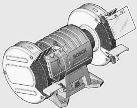
H306paXeHHbIe coCTaBhbIe yactn
HymepaunipnepctabneHHbIXKOMNOHETOB BblnoIHeHa n0 136paekhenHO h cTpaHnue CnnIOCTpaHnM.
1Koxy
23aKIMHaIraKa
3Ппхнмнофларец
4OnopHbIΦnaHeu (GBG6:DbvXacThb;GBG8:OHOAcTHbI)
5UHnΦoBaIbHbIuHnHdJIb
63aunTHbI KOKxyX
7OTBepCTHINKpENHeHH
8BbiknloaTeNb
9KpennneHneJna3aunTbIOTNcKp
10 3aunta O Hcnp
11 Onopa dnia 3aTOrTOBKn
12 BnlouHbI KIOU
H3o6paXeHHbIe HnH OHcaHHbIe npHaadJeNxoCTHe BxOaT B cTaNapThbI ObsemocTabKn. IOnHb accpTmEHT npHaadJeKHOCTe BbHaJTeB hawe nporpamme npHaadJeNxoCTe.
DaHHbOwyme
3HaueHHaBYKOBOH 3MHCCHN ONPeDeJIeHbI B COOTBETCTBHN C EN61029-2-4.
A-BBSeHHHy yPOBeHb 3ByKOBOr DaBHeHn 3JeKTPoHNCTpyMeHTa 06bHNO Hxke 70d5(A). HeIOcTOBepHOCTb N3-MepeHn K =3d5.
BoBpema paobtbyypoBeHb Wyma MoXeT PpeBbICHTb 80d(A).
PImmeHnIte cpeCTBa 3aunTbI opraHOB cyxa!


Pycckn|95
3aBHeHne o COOTBeTcTBn
MbIaBnEMnoHauyEHNOHmHyOToBTcTBeHHOCt,HTOONHCnHBIpa3DeneTExNHueCKneDaHHBeIPOJyKTOTBeueaETBCEMCOOTBeCTByUoUMNIOLOKeHnAMIupeKTHB2011/65/EU,2014/30/EU,2006/42/EC,BkIouaNXn3-MeHeHHa,aTaKaKeCneYIOHM HopMaM:EN61029-1,EN61029-2-4,EN50581.
Texnueckanokymentau (2006/42/EC): Robert Bosch Power Tools GmbH, PT/ETM9, 70538 Stuttgart, GERMANY
Henk Becker
Executive Vice President Engineering
Helmut Heinzelmann
Head of Product Certification
PT/ETM9


Robert Bosch Power Tools GmbH 70538 Stuttgart,GERMANY Stuttgart,01.01.2017
TexHHueckne daHHble
HcnoIb3yIte 3eKtPOHHCTPymEt TOBko C3aunTOIOTNcKP10.NckpblnpedctabnIcTcO6oONacHOCTbDnRA3HMOrT3aKeYbOKpyKaIOUne npEdMeTbI.
MoHTpyIte KpeIeHHe IJIa 3aUHTbI OT NcKp 9 C nOMO
-Пикpenite c nOMOь BOBHTOB 3aunTy OTNCKp 10 KKpePnneHNO dna 3auNTbI OT NCKp 9.
MoHTnpyTe OIOpyDn3aTOrOBKn 11, KaKn3o6paJxHoHa pncyHKe.
He MeHnTe MecTAmn PpaByo H neByo Onopy dnn 3a roTOBKn 11. Haupe pacCTOHHne Mekdy onopoi dnn 3aroTOBKn 11 uHnFOBaIbHM KpyrOM 6yEt CnHkOM 60bHm. PnP 60bJWM pAcSTOHHN Bbl He octatoHNO 3aHnEhbl OT pa3NeTaIOUxCnKp. PnBpaueHHn UHnFOBaIbHm KpyrMOeT a3raHyb 3aTOBky, YTO MOKeT pINBECTH KTPaBMam.
Perynphno npOBepnTe pacCToHHe MExdy onopoI dna 3arotOBKn 11/kpenneHem dna 3aunTbO tN cKp9 N uHFOBaBbHbIM Kpyrom, npH Heo6XoHMOcTH Otperynpyteero.PacCToHHe ot uHFOBaBbHO rKpyra


96 | Pycckn
He Donxho npebblwab 2 MM. Pn npeBbIeHHN 3TOrO pacctoHn He oecneuBaetcdoJnxHa 3aunTa OT NcKp.Bpaauohmca shnfoBaJbHb Kpyr Moxt 3aHTHytb 3aTOBky, yTO qpeBaTO TpaBMAMn.
MehnTe ⅢNΦoBaIbHbI Kpyr,ecNI KpEnIe Hne IaIHTbO T NCKP 9 yXe HeIb3B 60JIbWe HaCTponTb Ha pacCToHHe O T ⅢNΦoBaIbHoro Kpyra MaKc.2MM.
Cmeha uHFOBaBbHbIX KpyroB
PepedIO6bIMM MaHHyIaIcHMM c3JeKTPoHNCTpyMeHTOM BbITACKBaIte WTeNCEb H0 p03eTKH.
Donycthmoe uHcno 6obopotOB pa6oery HnCTpymeha doJxho 6bIb He MeHee yKa3aHHoro Ha 3NeKtpOHnH CTpymeTe MaKCHMaJIbHorO uHcna 6obopotOB.OchactKa, BpaiaouaacrC 60JIwe, Yem DonyctmO CKopoCTbIO, MOKeT pa3OpBaTcH pa3neTeBcB INPOCTpaHCTBE.
MeHHeIeIINFOBaIbHbI Kpyr,ecnTOJIuHa MaTePnAna Ha HEMyMeHbIbnacbdo10MM.
- Otnyctnte 3 BnHTa Ha KpbIuKe 1 H CHNMIte KpbIuKy 1. PnpdepnTe WnHPOBaJIbHbI Kpyr pyKaMn B 3aunTHbIX pyKABuCaX NOTKpyTnte 3aKHMHyraKy 2 Ha WnHPOBaJIbHom WnHdene 5.
YkaaHHe: BbIcTypaIoUm C neBoi CTOpOHi 3neKToPOnHCTpyMeHTa 5nInFOBaNbHb 5nHHdEbn 5 nMeT nEbyo pe3b6y.
-CHMMTE PnIXHMHNOIe3 N IINIOBbHbN Kpyr COIINIOBbHOIro IINHdJI5.
-MoHTaX HOBOI UINHPOBaIbHOr Kpyra Ipon3BODnTcB O6paTHOIOCNEIOBATEbHOCTN.CHOBA HaeHbTe KpbIuKy1,KpeIKo npHKaB ee,II pHKpyTHe ee c NOMOJIbO 3 BnHTOB.
IopnpabBte C NOMOuBIO TOUINbHOro KAMHcNOnb3OBaHnBHe HekOHueHTpUHbIe WInNoBaHbIe KpyrNepeJHX DaJIbHeHMM npImeHHeHem (npHaNDNeXHoCtN).
Otcoc nbinn nctpykkn
PbIbHEKOTOpbIX MATEpHaNoB, KAKHAp., KpacOK C COepeKaHHEM CBnHua, HEKOTOpbIX COPTOB DpeBeCnHbl, MNHepaIOB HMetaIIOB, MOKeT 6bIb BpeHNO Ia3IpoB Oy. PInKOCHOBEHNE K bIbN N NoJaAHNc EIN B DbxAtenBbIe NITM MoKET Bbl3BaTb AIIneprHueckne peakun H/nn 3abObeHAnh DbxAtenBbHx NTeH onepatopu nn HaxoJurecoB BnHn3 npcoHana. OnpeJeHHe Bnbl NpHn, HAp., Ny6a6by4, CnTaHTCR KaHcpeoreHbHMn, OocEHHO COBMeCTHO C npcaKaMa DN o6pa60TK npeBeCnHbl (xpomat, CpedtBO dna 3a UHTbl DpeBeCnHbl). MatepHaN cOpeXaHHem Ac6ecTa pa3peeaetc O6pa6aBbATb TOnbKO CneuaNAInCTAM.
-XopoOIO npOBeTpBaIte pa6ooye MeCTO.
- PeKOMeHnyETcNoIb3ObaTbcpeCnnpaTopHOMaCKoN CΦnIbTpoM KnaCa P2.
Co6nOdaTe DeIcTByUoUe B BaWey CtpaNe npEtnncAnHn.
JnO6pa6aTaBbAembix MaTePnaNoB.
H36eraTeCKoJIeHHa bInHa pa6OeM MeTe. IbIb MOKET NErKO BOCIIaMeHrTbCra.
Pa60Ta c HcHctpymeHTOM
BknHueHHe 3eKtpOnHcTpymEnTa
YuHTbIaBte HanpXeHne cTe! HanpXeHne HCTOHN Ka TOKa DOJIIXHO COOTBETCTBOBaTb DaHHbIM Ha 3aBOdCKoT a6JIuHKe 3NeKTPoHHCTpyMeHTbHa 230 B MoTy pa6OtTa b TaKke H npn HanpXeHHN 220 B.
PpOBepaIe 1HnFOBaIbHbIe HNCTpyMeHTblpeiHcONb3OBAHHem.1HnFOBaIbHbI HNCTpyMeHTdoJXeH6bl6Be3ynpueHO MOHTnpoAH N B COCTOHN CBO6OHO BpaAaTbc.BbINONHTE pO6Hoe BKNIOyeHe 6e3HarpyKc MAKCMHaBHO qACTOTOH BpaJeHHMNMy Ha 1 MNHyTe. HeCNIOb3yTe NOBpeKeHHble,HEPOBbIe INH Bn6pRpyOuIe 1HnFOBaIbHbIe HNCTpyMeHTbl.1OBpeXeHHbIe 1HnFOBaIbHbIe HNCTpyMeHTblMOrYt PAcKOToBcN nPiNbEcTN K TpaBMam.
BkIIOueHHe/BbIKIOeHHe
B CENX 3KOHOMH 3NEKTPO3HEPRN BKNIOUaJIe 3NEKTPONHCTPYMEHT TOIbKO TOrda, KOrDa BbI c6bnpaTecb pa6oTaTc HIM.
-Дя BKNIOUeHn3JIeKTPoINHCTpyMeHTa NOBepHInTe Bbl-KNIOUaTeIb 8B NIOJIOKeHne «I」.
-ДЯВБИКПIOUeHNe3JIeKTPoINHCTpyMeHTa NOBepHITe Bbl-KIIOUaTeJIb 8B NIOJIOKeHHe «O».
Yka3aHHNo npmHeHnO
IcnoIb3yIe IIOI 6OpaBabHn TBepDocnBaHbIX 3aOrToBOK WInIOBAbIbHbIe KpyrHa OCHObe Kap6nJa KpeMHnC (npHAnEckHOCTN).
3aunuane Te IINFOBbHbH HNCTpyMeHT OYapOB, TONKOB NNNXHPbIX PATEH.
-Nonokte 6pa6a7b1Baemyo 3arotobky Ha onopy dna 3aTOTOBKn 11 nCtka npKMTe K wHIOBOBbHOMy Kpyr.ДЯ DOCTNIXEHN OINTMauNbHbX pe3yIbTaTOB WINHOBAHNA CIERKA INPEMEuaTe 3AROTOBKY TuJa-cIQA.3TNM DOCTHraetcpaBHOMepHBn H3HOC WINHOBAuBHorO Kpyra.
-BpemrO T BpeMeHn OxnaJdaIte 3aTOrBkY B OBe.
Texo6cnyxHBaHne n cepBnC
Texo6cnyxmbaHne H ouhctka
Pepedn6bIMMaHHnyaHmNc3eKTPoHNCTpyMENTOMBbITACKHBaTeWtencenbH03p03eKN.
Длбоcecne�нкаectbehнн He6e3onachpo pa60TbI cIeIyET NOCTOHH COepXaTB 3NeKtponHcTpymENT N BEHTNIAUHOHBIE QENB YHCCTOTE.
Ecn Tpe6yetc NomeHb Hyp, 0baaHtec h NaHpMy Bosch n B aTOpH3OBaHHy cepBnCHy MoCTepCKyIO nIeNkToHNctpymEnto Bosch.
CepBn KOncynbTHpOBAHHe Ha npEmdTncNoIb3OBAHn npOdyKuHH
TpokaIyIcTa, BO BceX 3aIpcax N 3aKa3ax 3aIpaCTeN O6raTeJIbHO yKa3bIbAte 10-3HaUHbI TOBapHbI HOpE P NO 3aBODCKoT a6blnue 3neKtpOnHCTpyMeHTa.
Pycckn|97
CepBnchmaMactepckar OTBETHa Bce Baun BonpocbI no pemOHTu 06cnykBaHHo BaWero npOyKta nNo 3aNaCTAM. MoTAXHbIe UpeTeKu HnHΦOpMaUIO No 3anuaCTRM BbHaiNeTe TaKke no aDpecy:
www.bosch-pt.com
KolneKTHB cOtpyDnHKnOB Bosch, npedocTaNIOuN KOnCynbTaun Ha npedMeT NcONb3oBaHN pOpyKUn, cydoBOLbCTBnEM OTBeHT Ha BCE BaUN BOpocbl OTHOCTeBHorO Hauen pOpyKUnn H e npHaNDJeXHoCTe.
BaWyTHNCKOE WOCCE, Bn.24
141400,r.XmKm,MockoBcKa o6n.
Pocn
TeN.:8 800 100 8007 (aBOHOK no PoCCnH 6ecnHaThbI)
E-Mail: info.powertools@ru.bosch.com
POnHyu n AkyaIbHyU HOpMaunO pacnoJooKeHH cepBnCbIX ceHTPOB INpneMHbIX nyKtOB Bbl MoKeTe noJyHtB:
- Ha oΦuɪnəl bHOM caɪte www.bosch-pt.ru
-1n6o no TenefoHcy npaBOUHO - cepBcHOn cnyk6bBoSch 8800 100 8007 (3BOHOK no PocCnB 6ecnnaTHbI)
Benapycb
HII P06epBouO OOO
CepBnchbI ueTp no 6cnyKBAHNIO 3eKtpOHHCTpyMeHa. yI. Tmnp3Eba, 65A-020
25.Γ.MnHCK
benapycb
Ten.: +375 (17) 254 78 71
Ten.: +375 (17) 254 79 15/16
a c: + 375(17)2547875
E-Mail: pt-service.by@bosch.com
OphiuanaIbHy bN h caiT: www.bosch-pt.by
Ka3aXcTaH
TOO «PoBept BoW»
CepBnChbI ΣeHTp IIO 06cnyKbAHNo 3neKtpOnHCTpyMeHa
r.AmMaTbl
Ka3axCTaH
050050
np.PaBIM6ka169/1
yr.yn.KommyHaJIbHaI
Ten.: +7 (727) 232 37 07
aKc + 7 (727)2330787
E-Mail: info.powertools.ka@bosch.com
He bblpaibaiTe 3nEketponHcTpymEnbI B bblTOBoMycop!
TolbkoДягстан-челов EC:
Corgacho Ebponecko Dnpektnbe 2012/19/EU O ctabix 3neKtpuuecknx H 3neKtpoHHbIX INHCTpyMeHTax H pnp6opax H aKeBAthomy PpeDnncAHIO HaMOHaIbHO- ro npBa, OcnyKBWne CBOI Cpok 3neKtpoHHCTpyMeTbI DOJKNbI OTdJIbHO
coBpaTbcaHcdaBaTbcaHaKoIOnHuecknUHCTyIO yTHIN3a-
Bo3MOXHbI H3MeHeHHa.


98|YkpaIhcbka
yKpaIHcbka
Bka3iBkn 3Texhikn 6e3neKn
3aranbhi 3actepexeHHn enektponpunadib
YBABA
Дязхсту bIDурахжнэ eNeKTPHUM CTPyMOM,ТаBM Ta noxeki niDvac poBToN 3
eneKtpoiHCTpyMeHTamn Tpe6a3BaXaTH Ha npHHcNIOI npabNa 3TexHkN 6e3neKn.
Ipepeeknnyataucio eneKtpoHCTpymEny npouHTaB BcI BkazIKN 3TexhIKN 6e3neKN i do6pe 36epexitbix.
Пд NOHITAM «ЕКТЮИСТРМЕТ», со ВИКОПСТОВЕТСУВКАЗИКАЗ TEXHIKI 6e3neKи, MaTeBсЯ Ha yBa3i eNEKTOHCTPМENT, со пацIOc BiD МepeXI (i3 Ka6eJIEM KHNBEHHA) abO BiД AkymYIaTOpHoi 6aTapei (6e3 Ka6eJIa KHNBEHHA).
Be3neka ha pobooy Miciu
TpmaTe CbOe pOboye Mice BcHctOri 3a6e3neTpe Do6pe ocBtIeHHn po6oTOmCi. Be3nA abo noraHe OCBITIeHHHa POBOOMy MciMoKytb PnH3BeCTn Do HeuacNHx BnnaKIB.
He npaioiTe 3 eNeKtponpnaIamO y cepeobuI, de icHye He6e3neKa Bb6yBbAcniOk npcyTnoCTi ropoux piHn, ra3iB abo nnny. EKeTpponpaIaM MoKyTB nopOxyBaTH iCKPN, BiJ AKNX MoKe 3aImMaTcN aHn a6o napn.
Pid qac npaqi 3 eneKTPoPnPAJOM He nipnyckaiTe do po6oyoro micu dite Ta iHnx IIOJe. Bm moKeTe BtpaHTN KOHTPOB HAD npHJAOM, KxO BaA yBa 6yIe BiDBepHyta.
EeKtpnHa 6e3neKa
Wtencenb enektpponnady noOBHH nixxodHTN do po3eKn. He 03BONrCTbc mHTH niocb B wTeNCeni. Ipa o6oTn 3 enektpponnnaamn, uO MaHb 3axnche 3aemHeHH, HE BHKOPNCTOByTE aanTepn.
BukopnctaanopirihanbHoro stencela Ta HanexHoi po3eTKMehuye pnsK ypaKeHH enektpnHM CTpyMOM.
YkaTe KOHTaKtY CaTnTH Tina 3a3eMneHMM NOBepXHMN, HAnp., Tpy6amn, 6atapemn ONaJIeHH, INITAMn Ta XOJIOINbHKNkAMn. KOni BaWe tINO 3a3eMneHe, icHyc 3ibIbIeHa He6e3NeKa ypaKeHH eNEKTPNUHMM CTpyOM.
3axnauTe npnaBid Douy ibonr. Ionaanra BOn B eektpponpna36bnyyepn3K ypaKeHH eektpnHm CTpyMOM
He BnKOpHCTOByIte Ka6eB nIpeHecenHH eNkTpOpPnADy, NIDBiWbAHnA bO BHTryBaHN Htencn3 pOeTK. 3axuAaTe Ka6eB BiD Tena, oni, roctpx KpaIB Ta DetaneH npnady, zo pyxaOTbc. NoKoJKeHn ABO 3akpyeHn Ka6eB 3ibWyC pN3NK ypaXeHH eNkTpUHM CTpyMOM.
Длгьошхix po6it 06OB'3KOBO BHKOpHCTOByTe Nnue TaKn NOOBxBya, lo npHaTHN DnI 3OBhiwix po6it. BHKOpHCTaHn NOOBxBya, lo pO3paxoBaHn Ha 3OBHIi Hpo6tN, 3MeHwE pH3NK ypaJexHRe eneKtpuHm CtpyMOM.
Ako He MoKHa 3aNo6iTH BHKOpHCTAHHO eKeTpOpiHnady y BONOromy cepeOBnui, BHKOpHCTOBVHTe pNCHoI 3axxCHOB BMKHeHHA.
BukopncTaHH npctpo3axCHOrBO BmKHeHH 3MeHnue pN3NK ypaKeHH eNeKtpnHm CTpyMOM.
Be3neKaIIOeI
Bybte yBaXHHMn, cnIkyTe 3a THM, 10 Bu po6Ht e Ta pO3cyuINBO NOOBtcec nI qac po6OTn 3 eNkTponpnaDom. He KopnctyTeC eNkTponpnaDom, kUo Bu CTOMneHi a60 3hAxOHTecn iN diIO HApKOTKnB, cHnPTnHex HANOIB a60 NIKB. MItb HeyBaXhoCTi npn KopnCTyBaHHi eNkTponpnaDom MOKe pIn3BeCTn Do cepNo3HX TpaBM.
BraIte 0c06ncte 3axnche cnpdxkehna Ta 06o'3KOBO BraIaTe 3axnchiOkynnp. BraIaHn OocNCTOrO 3axnCHOrO cnpdXkHeH, AKn Hap.. -B3aJIeKHOCTi BID BNDy poBt -3axnCHOI MaCK, CneCb3yTTA,IO He KOB3aETCB, KaCKTa HabyuHNKIB, 3MeHUYe PnHK TpaBM.
YHnKaIe BnndKOBOrB BMnKaHH. Nepu HIX BBIMKHyTH eNekTpOpnlaD B enekTpOmepeKy a6o NiEcdHaTHaMyyIaTOpHy 6aTaPeIO, 6paTH IoroBpyKn a6o nepeHoCHTN, BneBHIbCh B ToMcy, 10eNekTpOpnlaD BmKHyTH. TpMaHH NaJIbua Ha BmHKaui NiJ uac npeHeceHH eNekTpOpnlaD y a6o NiKIIoueHH B pO3eTKy YbIMKHyTO rPiNaIy MoKe np3BeCTN Do TpaBM.
Pepd TMM,AK BMHKaTH eNEKTPponpHnaD, np6epiB HanaorOxyBaNbHI iHCTpyMeHT Ta raIKOBNI KIOU.
Ipe6yBaHHHa HanaOxyBaHbHoro IhctpyMeTa a6 KIOUa B uactHI npHAp, 0o obeptaetcb, MoKe np3BecTn Do TpaBM.
YHnKaIe HnepnpoDHoro NonoXeHH Tila.36epiraTe CTKe NonoXeHH Ta 3aBxN 36epiraTe pIBHOBy. UeO3BOInb Bam Kpaue 36epiratn KOHTpOBn Had eNEKTPoPnPaIaOM y HeCNOiBaHN CNTyaIrx.
BdraTe npHaTmOJr. He BdaTe npocToHn OJrTa npKpacn. He nctabnaTe BOscca, oJr Ta pykABuI Do Detaneep npnaDy, 0o pyxaoTbCn. PocTOpHn OJr, DOBRe BOLOcc Ta npKpacn MOxyTb NotpaHTN B Detani, 0o pyxAotbcn.
KIO icHcMoxNtBicMbMOHTyBaTHnNOIbIDCMOKTyBaNBi a6o NnoOyNoBnIOu npHCTpoIpeKoHaTecn,oo6BoHH 6ynDobpe nEHaHITa npabHbHO BHKOpNCtOByBaHNc.BHKOpNCTAHnNIOBIDCMOKTyBaNBHO pNCTpOIO MoKe 3MeHHTNe6e3neKn,3ymOBnEHINOM.
IpaBnblne NOBdoXeHH Ta KOpHcyBaHH enEeKtponpnaamn
He nepeBaHTaxyIte npnIad.BHKOpHCTOByTe Takn npnIad,IO CneuaIbHo npN3aueHHIgBIDNOBIDHOI po60TH.3 pIpaTHM pnpAOM Bn 3 MeHUM pI3NKOM oTPMaTe Kpaui pe3yNbTaTHpo60TH,AKUo 6yTe npauOBAuN B 3a3HaueHOM dyIa3oHI notyXHOCTI.

yKpaHcbKa 99
He KophtyTeca eneKtpponpnaDom 3 NookKeHHBMHKaem. EneKtpponpnaI, AKN He MoXHa yBIMKHyTn abo BmKHyTN, c He6e3neuHm i Ioro Tpe6a BiDpMoHTyBaTH.
Ipeep THM,IK perynIOBATHO-He6yNb Ha npHnadi, MInaTH npnaAa 6o XOBaTH npnaD, BHTarHtB WTeNCb i3 po3eTK Ta/a6o BHTarHtB akymyNtOpHy 6atapeo.Li nonepeKByaBbHi 3axOJ3TexHik6eNeKn 3MeHNyTOb PN3NK BNaNKOBOrO 3anyCKy npnaNy.
XoBaHTe eNEKTPonpHnAa, kHMn Bn came He KopHCTyETecb, BiD dIteR. He Do3BONaHTe KopHCTyBaTHcENEKTPonpHnAaOM Oco6am, 10 He 3HaHomi 3 HOrO p6oToO aBO he YHTaH N I Bka3iBKn. y pa3i 3actocyBaHH HeNoCbiueHmN Oco6am nPnAaH HeCyTB C6i He6e3neky.
CTapaHNO dOrnaJaTe 3a enekTpponpnaDom. NpebipraTe, u66 pyxomi detani npnady 6e3dorahno npaouBann Ta He 3aiDann, He 6ynn nookdoxeHmN abo HactlbkN nookdoxeHmN, u66 ue moTn BnHHytn Ha yHKIOHyBaHN eektpponpnaady. Nookdoxei detani tpe6a BiDpeMOHTyBatn, nepuHX KOpHCTyBatncn HmN 3HOB.BENka KInbKicTB HeUacNHx BNnAikIB cnpnuHnAcTbcra NorAHM DoIaDom 3a eekTpponpnaadam.
TpmaTe pi3aHbHI iHCTpyMeHTn HArOCTpeHHM Ta B uHcTOTi. CtapaHNO dOrIaHyTI pi3aHbHI iHCTpyMeHTn 3 roCTpIM pi3aHbHM KpaEM MeHwe 3acTpaHO TB JaERWIB EKcnnyataii.
BHKOPNCTOBYIe eNEKTPponpnaIa, pnpnaIaIdo HbOro, po6oui IHCPTpyMeHTn. i. BiINOBiHIO do uNX BkA3IBOK. Bepitb do yBar npn cybomy yMOBN po6OT Ta cne- uphiKy BHKOHyBAHOIpo60TH.BHKOPNCTAHH neEeKTPponpnaIaIb npo6IT, dIy aKHX BOHN He neped6aehi, MoXe np3BecNTdo He6e3NeHHxCITyaqi.
Cepbic
BidabaBte cbi npnnd ha peMOHT NHWE KBaniikOBAHM faxIBaT M Ta NHe 3 BHKOPHCTAHM opnirhaBnHex 3aNactHH. Ce 3a6e3neuHb 6e3neuHictb npnady Ha DOBTH vac.
Bka3iBKn 3 Texhikn 6e3neKn dIa DBOCTOPOHHX uNifyBaIbHnx MaunH

Bdraite 3axnchi okynpH!
HadiHo 36epiraTe eneKtpponpnaIa, kkuo Bn He KopcTcyTecn Hm. Micue nla 36epirAHn NOBHHO 6yTu cyxMa Ta 3akPbTaHC Ha KIOU. Lc 3anoiirao noKOJKeHHo eneKtpponpnaIay nia vac 36epirAHn abo BHacIIOK BkOpncTahHn HeocBIDueHmN OOCaMn.
He Kophctyntecn eeneKtponpnaIam 3 nookdoxeHm eeneKtpokaenem. Raio nia vac po6oTH eeneKtpokaeb bye nookdoxeHo, He topkaTeCn nowkoDxehoro eeneKtpokaen i BHTaRHTb Wtencenb 3po3ETKn. NowkoDxehn eneKtpouhnp 3bInbUye He6e3neky ypaXeHH eneKtpuHNM cTpyMOM.
Perynphno nepebiprae tshyp ta bidae noro B peMOHT BAETOPH3OBAHy cepbichy maICTepHIO eNektpnpnaig Bosch. Minrte nookdkeni noobkbya.i Ine 3a TaKx yMoB BaIw enektpnpnaia i naJI 6ye 3aIIaATnc 6e3neuHIM.
PyKoTKn 3aBxJH MaOTb 6yTH cyXHMn i He 3a6pydHeHHMOniEo a6o MaCTHnOM. Xnpi pyKoTKn BnCnI3aOToB 3pyk i npn3BOJrTO BpTaN KOHTpONu HAD npnlaDm.
BMHKaIe eeneKtponpHnad B MepeKx, 0o HaneXHHM 3a3eMnHe. B po3etui B noOdBKyBaHbHomy KaBen I Mae 6yTH CnpabHn 3axnCHn npOBiD.
BnKOpHCTOByTe NHee npnaJa, 0ne nepe6bayhe i pekomeHdoBaHe Bnp6HnKoem CneuaIbHO nn zuboro eNeKTPponpnaNy.Cama nHe MoKJIbIcTb 3aKpInnHn npnaJaHa BaWOMy eNeKTPponpnaDi He rapaHTye Ioro 6e3neue HnKOpNCTaHH.
Donyctma Knbkictb oebripo6o0rO IHCTpymenta NOBHHA AK MIMYM BIDNOBiAta MAKCnMaIbHi KINbKcTi oebrip, 33a3Haeha Ha eEKeTpOpnna.i. Pnla, 10 oebraTc bWuDwe Do3BoneHOrO, Moke 3NaMatnc i pO3Netitca.
He BHKOPHCTOByTe noKoJXeHi pOboUi HcTpymEnI PepeKD KoxHHB NKOpHCTaHHM nepeBipnIe WnidyBaNbi KpyrHa npeMet BiKoNIB I triuHN. Raio eekTponpHnad a6o poOuyn IHcTpymEnBnab, nepeBipTe, Hn He noKoDnBCB iIN, BHKOpHCTOByTe Nne HenoKoDxKeHn poOuyn IHcTpymEn. Picna nepeBipKn mOntaxy poOuro IHcTpymEnBa cami i Inwi ocObN, 0o 3NaOaTBcN NobNHy, NOBHNI cTaTH TAK, 0o6 He 3haoNDnC B NIOouHI poOuro IHcTpymEna, 0o o6eTAeBcA, nicra 0yo YBMKnHb eekTponpHnad Ha Ody XBHNHy HA MAKCMnblhy KInbKiCTb 0eptIb. NoKoJXeHi poOoyi IHcTpymEnH 6InbIciNo lamaiOtc Niq cac Taokoi nepeBipKn.
KophtyTea eneKtpponpnaomnne 3axhctom Biickop 10.1ckpnMOxTyb nooKOJTH Ooi abo nidaanHTOtouyoui npedmetn.
Pnac wniybaHHa Haxmnae 3axnct BiD ickop 10 kOMora HxKue. Pnac wniybaHHa Metanib netaTb ickpN.
Perynpho nepebipate Bldctahmbix onopo3arotobk 11/kpinneHHm Ira 3axhcTy Biid ickop 9 taWlidybaHBM KpyrO i3a He06xHicTHOBiDperyIOte II.BiDCTAHbdo WlidyBaHbHorO kpyaHE NOBHHA NEpebUyBatN 2MM. Pn pepeibweHHIciBIDCTaHI He 3a6e3neuycTbCra DoCTaTHII 3axHCTBID icKOp.OBeptaoCb, WlidyBaHbHN Kpyr MoKE 3aTARHTN 3arotobky, UO MOKe Pn3BecTHIO nopaeHB.
PiNbOdbTe 6p06NbBOHy 3aTOBky NHe Do yBIMKHeHOro eNEKTPponPnAdy IBMHKaIte eNEKTPponPnAd NHee nicna iNImHaHHo 6p06NbHOHO3aToTbKn. O6p06NbBOHa 3aTOBKa MOKe paITTOBpyxATHCJ.


100|YkpaIhcbKa
HikonHe nIDBoBte 3aRObky 36Oky nI d IuIpyBaIbHN Kpy, uO o6eptac. UIniPyTe 3aBXn cnepey. nI diEIO uINiPyBaIbHO rO kpyra, uO o6eptac, 3aRObKa moKe BnPbAtncr y Bac i3 pyk i npnaBecTn do npaHeh.
HikonHeDOTopKaItecDoWnifyBaNbHoroKpyra, 0o o6eptaetbc. Lc MoKe npHBecTH Do TAAKKNX nopahEnb.
PicnBumKHeHH npHady He raHbMyTe WnifyBaBHn Kpy npHTCKyBaHHM 360ky. Bhacniok o6epaHH nifyBaBHoro kpyra 3arotOBka MOKe BnPaTHcY bAc i pyk i npHaBeCTn do npaHeHb.
BdraTe po6ouH φapTyX.CnIkyte 3a TM,io6 icKnHe CTbOpUbaH He6e3neKy dIn iHnx IIOJe. Pn6epiB rOpii MaTepiAn, 30 3hAxOJrTbc no6n3y.Pid yac WnidyBaHH MeTanib NetTb icKn.
TpmaTe po6oecmicueBcHctoti.OcoBnBy He63nekyraBnIOTbco6oIO cymiuMATEpiAnIB. NIN JERKnx MetanIMoKe cnaaxyBatn a60 B6yxatn.
CHMBOJIH
HnKyuOaHcMBOJINMOxyb3Ha06nbCBAmpn KOpNCTyBaHHI BaUHM enEeKTPoPnpIaOM. ByNb nacka, 3anam'YaTHe TcMBOJIN Taix3HaueHn. PpaBnIbHe pO3ymHn CMBONIB DOnOMoKe BAM npaBnIbHO ta He6e3neuHO KopNCTyBaTHc enEeKTPoPnpIaOM.
CNMBONnTaTx3NaueHHA

He nictabnnte pykn B 3ohy
wnifybanbHoro kpyra, konn
eneKTpoinctpyment npaioe. TopkaHH
do wniifybanbHoro kpyra Hece B cobi
he6e3neky npaehHH.

BdraTHe HabyuHnK. Lym MoKe NOKOHTN Cnyx.

BdgaTte 3axnch okyanr!

BdraaTe nnno3axncHy macky.

BdraaTe 3axnci pykabnci.
TexhiuHaDokymeHuaJia(2006/42/EC):
Robert Bosch Power Tools GmbH, PT/ETM9, 70538 Stuttgart, GERMANY
Henk Becker
Executive Vice President Engineering
Helmut Heinzelmann
Head of Product Certification PT/ETM9

Robert Bosch Power Tools GmbH
70538 Stuttgart, GERMANY
Stuttgart.01.01.2017
MoHTax
Pepd6ydb-KNMMAHInyuaiMa3eNEKtpponpna-domBHTHHTbWTeNCb3po3EKn.
3akpinibteeneKPTpoHCTpyMeHT BiJNOBIDHMnTBHTAMNB4 nepebdaeHHx dna zbo ro TBopax 7 do Bepctaka / po6ooyi nnn.
MOHTAX 3axHCTy BiD icKOp/onopn 3arOTOBKN (INB.MaI.A-D)
Kopctytee enktpponpnaomnne 3axhctom Biickop10.1ckpnMOxTyb noXKOHTN Oi a6o npanNTOTOUYOUI pEmTH.
MOnTyIe KpInIeHHeIa3axHcTy BiI icKOp 93a DOnOMOrHOo6xTBnHTIB.
- PnHKpinitb 3axHCTB iD icKop 103a donomorOIO RBHHTIBdo KpinneHHa 3axHCTy BID icKop 9.
-MoHTyIeOnopy3arotobkn11,AK306paKeHoHaMaHIOHky.
He minnTe micum npaby i niby onopy 3arotobkn 11. Ihakwe biDCTaHb MIX onopoio 3arotobkn 11i nnipybaNbHM kpyrom 6ye 3aHaTO BENKOIO. Ppi BENIKBIcTahi BN HeoctAHTbO 3axuHeni BiP03IaTHH ickop.ObeptaOuNCb,niDyBaBnH Kpyr MoKe 3aTHyTH 3arotOBky, 10 MOKe pnp3BecTH Do npapaHeB.
Perynphno nepebipnte BiicTaB mix onopoo 3arotobkn 11/KeinnenHm dna 3axncty Biid icKop 9 Ta WlifybanhM Kpyrom i 3a Heo6xHnicTIO Biiperynthe II. BiCTahN do wnlifybanbHoro kpyra


102|YkpaIhcbKa
He NOBHHa NepeBnuyBatn 2 MM. Pnpne6inbweHHi ciic BiDcTahi He 3a6e3neueyCTBCa DOCTAHII 3axnCT BID icKOp. O6epTaOuCb, uNidyBaIbHNI Kpyr MoKe 3aTrHyTH 3aTOToBky, UO MoKe npN3BeCTn Do nopaHeh.
3amihtb ⅢiHyBaBnH Kpyr, RaIO KpiIeHHN DnI 3axHCTy BID icKOp 9 He MoXHa yCtAHOBHT Ha BiDcTaHI MaKC.2 MM BiD ⅢiHyBaBnHO Kpyra.
3aima uicybaHoro kpyra
Pepd6ydb-KNMMAHInyuaiMa3eneKtpponpna-dOMBHTHbWtencelb3p0eTKN.
Donyctma Kibkictb o6eptibpo6ofoi hctpymenta NOBHnA KMIHym BIDNobiDaTH MAKCHMaBHH KInbKocti o6eptib, 3a3auehaHa enekTpponpnnadi. PnpnaIa, 10 o6eptactbc HWBdwe Do3BOneHOrO, MoKe 3NaMaTnc i pO3neTITncr.
MiHnTe U#yBnKpyr, AIO TOBnHa MaTePiaNy Ha HbOmy 3MeHnIacn do 10 MM.
BidnycttB 3rBNHTnHa Kpnu1i 3HIMITb KPNKUky 1. PnrtpmaTe WnifyBaIbHN Kpyr pyKaMn B 3axnchnx pykabuaX i BiKpyTb 3aTHCKHy rAky 2 Ha wnifyBaIbHomy UnHHdeni 5.
BkaibKa: LlifyBaHbHn HnHnEnb 5, 0o BucTynae 3 nIbero6Oky enektpponpnaady,Mac nIby pIsb.
-3HIMITb 3aTNCKNH pnaHeCb 3i wNlipyBaNbHn KpyI3 wNlipyBaNbHO rNHHdJIe5.
MoHTaX HOBOI WnIpyBaIbHOrO Kpyra3dIChHOeTcRy 3BOPoTHIN NocNIOBHOCTi.3HOBy HAdInbTe KPNuKy1, MiHO HATNCyBUN HA Hei, I npKpyITb II 3a DonOMOROHO 3rBNHTIB.
PonpaTe 6pyckOMIINIOBOIDKN (npnnaD) BHKOpHCTaHI HeKoHcHTpNHi IINiFyBaJIbHI KpyrNpeepix NoaJIbWM BHKOpHCTaHHM.
BicmokrybaHHnHny/tnpcn/ctpyckn
- TnTaknx MATEpianib, RaHnp., NaKoapab60Bx NOKPHTb, 1O MICrTb CBNHeu, DeaKHX BnIB DEpeBHN, MIhepanib i MeTany, Moke 6ytn Hne63neuHm DnA 3doPoB'
TopKaHH aBO BnHXaHHN nHy MoKE BnIKNKATy BAC a60 yocib, 1O 3hAXoJrbcnOBnH3y, anepriHi peAkui ta/ab0 3axBOHOABHH NAnXbHN XnAixiB.
PebHI BnIN nHy, KaH np, dyobnn ABO 6yKOBn nI, BBaxaIOBc KANePOReHHMn, OOCbNIBO B cNOlyeHHI 3 doabAKAMn IaOBpOKn DEpeBHN (XPOMt, 3ac6n dna 3axHCTy DEpeBHN). MATEPIAN, 1O MICrTb a3eect, DO3BOJIETCBcO6pOJIITn NInue CneuaIantam.
CniDkyIte3aDobpoIOBENTINJUciHO npo6OmyMICJI.
- PekomeHnycBcBnRaTH peCnipatOpHy macky 3
- pInbTpOMKnacy P2.
OoejmyteepnnpncicBIOoO6pOboBaHnxMATEpianIB, IOIOyBauiKpaHi.
YHKaTe HAKONHueHHNHy Ha po6Omy Mci. MoKe JERKo 3aMAtnCra.
Po6ota
TouaToKpo60TH
3BaKaIte Ha HanpyrB MepeKi! Hanpyra DKepeNa CTpyMy NOBHHa BiNIOBIATh 3NaueHHe, 0o 3a3HaueHe Ha Ta6nHcI 3 XapaKTepHCTKAMn EneKTPoPnPaNy. EneKTPoPnPaIa, 0o po3paXOBaHH Ha Hanpyr 230 B, Moke npauOBaTHaKoK i npn 220 B.
Pnebiprae uifybanbi hictpymentn peepeknyataciio. uifybanh mhcypmertMa 6ytN63dorahno MOHTOBAH T a BInho opeptnc.3diChitnb np0be BMKANH63 haBaHtaxEHn npHaBnui kibkocti oepTIN npHaAMnHa 1 XBn. HBNOPCHOBYte nookxehi Ta hepiBHNuifybanbi hCPTMYSnA BO taki. uO CnBHO BIPVOTb.
Nookkehi niipyBaIbHI iHCTpyMeHTM NOKytb lamatnci cnpnHHTn TineChi ykoKDKeHH.
BmKahHa/BmMknHn
3MipkyBaHb 3aoUaJxHeHH eNeKtpoeHepriB BMKAKeTe eNeKtpoiHCTpyMeHT NIIe ToDi, KOni Bn 36npaTeCb KopHCTyBaTcH Hm.
106yBIMKHyTneEeKTPoPnIaI, npHTNCHITb BmHKa8B NOJKeHHA
-Ⅲo6BmKHyTheneKtpponpnaad, npntCHITb BmHKaay8B nnoJKeHHA0
Bka3iBkn 0o0p060tn
IINOBpO6KN TBEPDCnNAHBNX 3aOTOBOK BHKOPNCTOBYHTIe IINiCyBaJIbHI KpyrHa OCHOBI Kap6iNy KpeMHIO C (npnla).
3axuatae uifybaHn kpyr Bi yapib, noTobxib Ta JNPOBx PAM.
-
POKlajitb 3arotOBky, kny notpi6ho biDwniFyBAtn, Ha onopy 3arotOBKn 11 i 3nerka npntncihTb ii do WnifyBaIbHoro Kpyra. Dna DOcRHeHHN ONITMAbHnx pe3ynbTaib wniFyBaHH 3nerka nepeCyBaTe 3arotOBky Tdyn-CIOH. 3aBnKn Ubomy 3noWeHH NNI FyBaIbHoro Kpyra HocHt b pIBHomipHn XapakTe.
-
YacBjIyacy oxoJnoJkyIte 3aRTOBky BBOJI.
Texhuihe 06cnyroByBaHHi cepBic
Texhihe 06cnyrobyBaHHiaouHenn
Pepd 6ydb-kaMHMaHInyuaiM3 eEnktpponpna-dom BHTaHrHtB wTeNCb 3 po3eKn.
6 enektpponpnaipauoBAB kicHO haidHIO, TPMaTe npnndi BEHTNnIuHI OTBOPB uHCTOTI.
Kaio tpe6a nomiHn iD'EnhyBaIbHH Ka6en, ce Tpe6a pO6HTn Ha fipmi Bosch a6o B cepBichm MaIcTePHI dne ENEKTPOIHCTpymentHBosch, 06 yHNKHyTH He6e3neK.
Cepbic Ta HadaHna KOHCyIbTauii 0do BnKOpNCaHHN npOdykci
PnB Cix 3aHHTAHHHX i npn 3aMOBHeHHi 3aHcyactHn,6yDb nacka,06OB'3KOB0 3aHaayte 10-3Haun ToBapHn
Kaatakaia|103
HOMep, 3x3haoDnBcRa Ha 3aBOcBki TaBnui jeneKtponpnaNy.
Cepbicha MaJIcTepeH BiINOBiCTb Ha 3aIHTAHnH CTOCBOH pemOH TY iTexHIVHOro o6cIyROByBaHH BaWOrO BnPO6y. MaIOHNK H B dAIIAX iInOpMaUIO uOo3aNCACTNH MoXHa 3HaHTn 3a aDpecoio:
www.bosch-pt.com
Komahda cnibpobitHnKIB Bosch 3 hadaHH KOHCyIbTauii
IOO BHKOPNCTAHN IPOyKii i 3aIOBOJENHM BiINOBICTb
Ha Baai 3aHTAHN CTOCBO HAIOWI PNOyKII Ta npnaia
do Hei.
TapahtiHe 6cbnyrobyaHHI pemOH teneKtpoHCTpymEny 3diChIOIOBcB iDIOBIHO DO BHMOR I HOPM BnTOBOTIOBAaHa TepiTopi BCIX KpaIH NIIeUe y fipMOnx a6o ABtopHOaBHnx cepBcHnx zehTPax fipMn «Po6ept Bou}. IIOPEPdKEHH! BHKOpctAHN KOHTpAkaTHIo npOyuKii He63neue B EeknPyataui I MoKe MaTH erATNBi HacniKn DnIzdoPob'A. BnTOBNeHHI PO3NOCbIQXeHHI KOHTpAkaTHoi npOyuKJI nepeCNIyEb3a 3aKohOM B adMIHlCTpAHBOMI IKPMHaHbHOMY NOPdKy.
UkpaHa
TOB «PoBepr BoSi»
CepBicHHIeHTpeEKeTPOHCTPymETIB Byn.KpaHH,1,02660,KuB-60
YkpaiaHa
Te.n.: (044) 490 24 07 (6araToKaHaJIbHmI)
E-Mail: pt-service.ua@bosch.com
OphiuiHn caT: www.bosch-powertools.com.ua
Apeca PeriohanbHex rapaHTINHX cepBICHN MaCTepeHb 3a3haHeBa HauioHaBbHomy rapaHTINHomy TaIHOi.
Ytwniau
EnekTponpnai, npnla i ynakobky tpe6a 3daBaN Ha ekoloriuho ncty nobtopny nepepo6ky. He BHKndaTe eNkTPOIHCTPymETB NOByTOBE CMIT8!
Jinwe dna kpaH EC:

BidnoiHO do cBponecBkoI npeKTHBN 2012/19/EU npo BIDnpaobBoH i eneKtpio eektonhi npnndi ii nepetboepenha B haoiHaHbHomy 3aKOHObAcbTi eektonpnpnndi,IO BWuNIM 3BXINBaHH, NOBHNNI 3daBaTNC OKPemO yTNi3yBaTNC eKOJIIOHIO CHNTM CNOCOB.
Moxnmbi3miHH.
Ka3aKa7a
EHdipyHHHcHIM YIWH KApactbPfAH naHdAnaHy KxATTabbHIN KypMbHnA naHdAnaHy XeHInderi OcbI HcKaybIK, COhBMEN bipRE KocBIMwAnap da 6Olybl MyMKH. CKeCTKti pactay KaNbl aknapat KocBIMwAda 6ap. OHmII eHipreH MemNekeT Typbl Aknapat EHMHkopnyCbHda XHe KocBIMwAda KepcetinreH.
EHdipy KHyH HcaybIKbIH COHbI, MyKa6a6eIHKeKpcetinre.
HMnopTaybI KOHTAKTIk MAnimetIH opamada Taoby MYMK
Ohimdi nai danany Mep3imi
OhMHINKb3MeTetyMep3iIM7Xbl. OhDipinreHmep3imHe bactan (EHnpy KHy3aybTTakTaWacBHaJdaXa3bnFaH) ICTeNl5XblCaKaTaraHHaOH, EHMJI TeKcepyC (cepBnCTIK TeKcepy) naIaNALy ycHbIMaNbl.
Kb3MeTKeHeme NaDanaHyBihBIn KaTeNikTepi MeH icTeH bHy ce6ntepinH ti3imi
TytKacbMeH Kopnyc6y3bnFaH 60nca,ehimni naDanaHa6hbi
-0HIMKopnycbiHaHtiKeNeIyTITbIKca,naJaIaNbHaBb3
TOKcMb6y3bIraHHeMeceOKuaynaycbI36oNca, naDanaH6aHbI3
- XaybH -WaaBH Ke3iHne cbiPTa (daIana) naIdanaHaBb3
Kopnyc iwihe cy kipce KpybIyHbHb Kocyu b60MaHb3
KENYUHKBHUBIKca,naHdaHaBb3
KaTbI dipin Ke3iHne naaanaHaBbI3
Uekriky6enrinepi
- TOK CbIMbIHbIH To3ybl HeMeCe 3aKbIMdAHybl
-0HIM KOpNycbHbH 3aKbIMdanybl
Kb3MeT Kepcety Typi MeH Xniniri
Op naIaIaNhyaH coH eHIMdi Ta3anay ycbHbIaNbl.
CaKray
KypfakKepeCaTay Kepek
XorapbI TemnepaTyKae3iHeH XaHe KYN CaynepePiHi AcepHHeAblcCaTayKepeK
- cakay Ke3iHne TemnepaTypaBih KeHET aybTKyBHAn Kopray KepeK
- opamacbl3 caTay MymKih EMEC
- cakay単apTapbI TpaIbI KocBIMwa aknapaI ay yuH MEMCT 15150 (単apT1) kkaTbIH KapaHbI3
TacbImaDay
TacbImandayKe3iHneOHMdiKynatyFAxHeKe3KeTReMEXAHKNBikBkNan etyE KaTah TbIbIM CaBHaDb
-6ocaty/xykTey Ke3HHe naKeTTi KbCaTbH MaunHaapdbn naDanaHyra pyKcat 6epimMeDi.
TacbImaaywapTAPbTaanTAPbH MEMCT15150 (5 wapt) KxkaTbH OKbHb3.
Kayinci3ik HycKaynapbl
3neKtp KypanDapbHbH Xannbl Kayinci3dk HcykaynbIKtapbl
HA3AP AYdAPbIHbI3
3nEeKtp KypaIapabH naiIaIaNyua TOKcoFbyi,

Bosch Power Tools 1609 92A 2H2| (17.8.16)

104|Ka3akwa
KapaKaTTaHy KHe KYin Kany KayiIne HcKaTaHy yiwTmEnDeI Heri3ri Kayinc3ik wapanapbH opbHaB13.
3NeKtp KypaBbN naDanaHyaD anBbN ocbl HcckaybIKapdbN 6apbIFbN OKbn Kayinc3dk HcckaynapbH opbHaHbI3.
Kayincik HycaynbkTpabHa naaanaHbnaf Hnektp Kypal aaybHIn KeiJeH Kyat anaTbH 3nektp KypanapbHa (Keinik KaBen MeEH) XHe AKKyMnTOpDn Kyt aataBn 3nektp KypanapbHa (Keinik KaBen Jok) KatbcIb nap.
Kymbc opbihbn kayinci3di
KymbpnhTata3aXHeXaKcbI XapbIKtanFaH XaHaJaYcTaHbI. Taptin Hemece XapbIK 60nMaHaH XyMbIC aMakTpbl Xa3aTaNbIM OKHaJAPfa anbl Kenyi MYMKIH.
XaHaTbH CyhBtBtKTap,ra3apHeMece WAn XbInFaH XapBbIc Kayini 6ap KopWayda 3neKtp KypanDbI naDanaH6aHbI.3neKtp KypanDaIbpyuWkbH WbIFapbln. WAn Hemece 6ynapdbKaHDbipyMmKin.
3NeKtp KypanDapbH naDanaHy Ke3Inde 6anapan Xane 6aca aadamapbI y3ak xepre weTetiri3. Ayitky Ke3Inde Kypan 6akblaybH KOFAITybiHb3 MymKiH.
3nektprKayinci3diri
3neKtp Kypan Wtenceninih aibipbipo 03eTkara cbHobikaxet. Aibipbl ekaHdae3reTp Mymkih emec.Kepre Kocynbl 3neKtp Kypanapmeh en kauHdainanTepnik aibipbnaaanaHa6bH3.3eepimereahaykehe Jkapamdbpo3eTKanapbI naJaAnaHy 3neKtpTOK CORY KayinIH TEmeHTeJI.
Kybip, kblbtaTbH Xa6bIK, nnta XaHe cybitkbu ChnKtI Jepre Kocynb Kypanap cbiptbHa Tmehi3. ErepeneHiz xepre Kocynb 6oNca, anktp Tofbihncof Kayni aptaB1.
3neKtp KypanapbH bInrpanaH,cbI3aH caKaTaHbI. 3neKtp KypanbHbH iHHe cy Kipce, on 3neKtp ToFbHbH COy KayinapTbpaBbl.
3nekp KpaanbIaBn Jxpy, acbn KOHO Hemece aBipbH po3eKadAn WbIFapy ywiH Ka6nbI naDanaH6an3. Ka6nbI bCTbIKTaH, MaJdH, eTKip WeTepen Hemece KpaanbIH XbINXbIMa 6oneKtpeInen anbc Xepde ycTaH3. 3aKbIMdaFaH Hemece WHeHenicken Ka6nb 3neKTP TOfbHbIH COY KayniH apTbipabI.
3NeKtp KypaIbImeAawbIK Jepde Jxymblc ICTceH3, TEK cbiptTaNaidanahyFa apHanfAH y3apTKbIHTB naDanaHBi3.CbPTNaNaidanahyFa apHanfAH y3apTKbITb NaIDanaHy 3NeKtp TOfBIhH COY KayniH TEmHeTei.
3NeKtp KypanbH bInFaNdbKopWayda naHdanaHy KaKet 6oNca, ABToMaTbI cKaTaHdbIpBbIaXbipATkbIbH naDaHaNbHbIbI. ABToMaTbI CaKaTaHDbIpFbIaXbipAtkbIbTb NaDaHaNY TOKcoFy KayniH TeMeHeTeJI.
Aaamdap kayinci3diri
CaK6onbIn,HeICTENKaTKaHbHb3Fa aipbKwaKeHn 60nin,3neKtp KypanbH petimEn naDanaHbHb3. 1apwafahXaFdaHa HeMece enitKiW,AnkorOnb
Hemece npi ocepiaactbHa 3neKtp Kypanbln naDanaH6aHbI. 3neKTP Kypanbln naDanaHyda cekyHtBik abaicbidik KaTbXkapaKaTTahynapFa anbIn Kenyi MymkiH.
Xeke caKaTbH KNIMJxHe aPdA bIM KOPFaHbW K03inipikTi KNIi3. 3neKtp Kypal TpyiHE Hemece naIaIaNyBHa 6aIIaNbIcTb IaHTYkBbU, CbIPrJaH da CaKaTaBtBn6TeHKe, cKaTaBtBnIeM Hemece Kynak CaKaTaFbIbIcNRAKTI Xeke KOpFaHbc Jka6blkTapbH KHO JapakatTAHy KayniH TeMeHDeTei.
Bikaycbn nainananyan aynak 60nbHb3.3neKtp KypabIn ToKkaXaHe/Hemece aKKymnTOpFa Kocya, OHkTepeReHde Hemece anIn KypreHde, 8uipyni 6onybHaKe3 XeKti3iH3.3neKtp KypalbH KeTeepin TypfAHa, 6apMaKtbl AxbpaTbIaTa YCTay Hemece KpybIfbHbKocybl Kynde ToKka Kocy, Jaa3aTaNIM OKfAflFa aIn bkenj MyMkiH.
3NeKTP KypanbH KocydaH andbH petteTin acnantapdbx kHe raKa KInTepiH anbictaBb13. AHaNaTaBH 6eKeTe TpyFaH acnH HeMeCe KINT JkapaKaTaHynapfa aBbIn Kenyi MYMkiH.
Kanbincb3de He KyinHe TpyMaHb3. TipeK Kyinde TybIn, epKaaAn 03iH3iCeHIMdi yCTaHb3. Ocbna ci3 Kytneren KaFdaJa 3JKeTp KypaNbI Jxakcbipak 6akbnacb3.
Kymbicka kapaamdbkim KniH3.Keh Hemece cahki KIM KMIeH3. Wauhbi3dbk, KIM XHe KOFnTbKO3FaMnB6enweKTepeH anbc yctah3.KeH KIM, 0weKeH Hemece y3bH wai Ko3FaMnB6enweKTepre THIOI MYMKH.
WahcopfbwXHe WAnTykbw Xa6bIKTapdbI KypfAHa, OApBnKocBnFAHbIFBaHxHe Dpybc nainanbHybHa Ke3Ketki3i3. WAnCopfbTbn naDanahy wAn ce6eInH 6oNtBn Kayinepdi a3aTadbl
3neKtp KypanDapbH naiDaanHy XeHe KtyT
KypaIbI aca kon JyKTeMeHi3. KymblcHbI3 yuHJ Xapambl3neKtp KypaIbIH naDanaHbHb3. Xapambl3neKTP KypaJIbIMeH KepeKi JyMbIC aMafBHa DpybIC api ceHIMdi JyMbIC icTeHi3.
Axbipatkbibdybicemec3neKtp Kypanbin naDanaan6anbi. KocyfHemece eHipyre 60ImaTbH 3neKtp KypanblKayinti 60bn, OHJKeHcy KaKet 6oIaBl.
KabIkpTpeTey,6nweKeTpH anMaTbpy HEmeCe Kpaanbl anbl KOIOaH anblH aHbIPbpo3eKaadH bIfapBb13 KHe/Hemce AKKyMnTOpbl anbl TactaHb3. By cakTBk apeketi 3NEKtp Kpaanblb Kaaycb3 KocbiNyBaH kon bepMeNi.
PnanaHbMaTbH 3neKtp KpAnapBb6anap KaIeTneTIN XaIra KOBbHbI3. OcbIaPdb6InMeTIN Hemece OcB eCKePTNIepePi OKImarAH aamap46yn Kypanbl naananyra Kon6epmei3. TaKiipEci3 aamap KOBbHa 3neKtp KpAnapBbKayin6oIaBl.
3neKtp Kypanapabih Ykblntb KytiH3. Ko3ranmbl6nweKteprin Keeprici icteyine Xhe Kentenin KaMbayha,6nweKteprin akaycb3 Hemece


Ka3aKa7a|105
3aKbIMdAmMaFah 6OnybiHa, 3NeKtp KypanblHbH 3aKbIMdAmMaFahbHa Ke3XeTki3iH3.3aKbIMdAnFaH 6nweKtepi 6ap Kypanbl NaDanaHyd an Anbl H XoHneH3.3NeKtp KypanlApBbHIn Dpybc KyTImeyi Ka3aTaBbIM OKfApaFce6en 60blkataDbl.
Keckiw acnantapdb otKip KHe Ta3a Kyide caKaTahb3. Dpybckytirhen Xehe keckiw xneKtepi otKip keckiw acnantap a3 KeNTenin, KecineiH 6etke OHa BarItanab.
3NeKtp KypanbH, Xa6dbkTapdb, anMaNb-canMaNb acnantapDbXahe T.6 ocbHyckaynapFa ca naiDanaHbHbI3. CohbiMeH xymbcIupTapmbEm opBHaTbH apekETepre Haazap aydabHbI3. 3NeKtp KypandaPbH apHaMafH xymblcTapda naDanaHy kayinti.
Kb13Met
3NeKtp KypanbHbI3bI TeK 6nIKTI MaMaHaFxaHe apHaynb6oWKeTepmexHcHTei3. Co apKblb3neKtp KypanbHbIH Kayinci3diRiH cKaTaNcb3.
Kon axkapnay 6inderine aphanfah kayinci3ik hyckaynapbl

Kopranhni Ke3indpikti Khiiiz.
Pnainanah6aHan 3neKTP KypabIn Dpybic cakTaH3. XataTbIn Xepi Kypfak Xhe XabInatbIn 6onyi Kepek.Ocbinna 3neKTP KypabI JkaTkaH XepiHde 3aKbIMdanybi Hemece TaXHipBeci3 aamap naadanaHyBaHa Konl BepMeci3.
3NeKtp Kypanbl3aKbIMdAnFaH Ka6eBmeh naDanaHa6Ban3. Ka6eB XyMbic icTey Ke3iHe 3aKbIMdAnFah BOnCa JeJI aHbIPbIH WbIrapbHbI3. 3aKbIMdAnFaH Ka6eB 3NeKtp TOfBiHbIH COy KayinH apTbIpaBl.
Kabenbi JyHJI Tpye Tekepin 3aKbIMdAnfah Kaenbi TeK Bosch 3nEeKTP KypanbIapbHbN ekinetti cepBnCTIK KbIMTeBiHE XoHDetiH.3aKbIMdAnfah y3apTbHII Ka6eIN H AnMaTbIpbHbIc. Co apKblb3neKTP KypanbIHbH KayincisdirH cKaTaNbI.
TytkanapbkyprKaTa3aKHeMaHcbI3KaFnaJa yctahb3.MaTykanap cbiprKa60bn6aKbIay Xofantyiba anblkenepi.
3NeKtp KypanbHnTnicti Tepinne Hxepre KocbINFaH ToK Xenicine KocbInbI3. Po3eKa MeH y3apTkblTa Kymblc ICTeTIH KopfainbH CBIM 60nybl KaXET.
Ocbl3neKtp KypalbHa apHanMaFaH XHe eHdpyWimEn YcbHbImMaFah Xa6DbIKTapdb naDanaH6bH3.3neKtp KypalbHa 6epiK 6eKiTy MymKHHiri 6apXabIKTap fHa Kayinci3 naDalaHydKaMTamacb3 etedi.
Anmbl-canmblacnantbHpyKcatetinren aHaHbIMdapcaHkeMInHe3neKtpKypaBnHa 6enrinenreHMAkCMMaIbIaHaHbIMdapcAblaHa cainKec6onybKepe.PyKcatetinrenHHKbIaam aHaHaTaBHKa6bIK6y3bInB,waBbInBKeTyMyMKIH.
Eby3bnfah anmblc-anmblacnntbna danan6anb3.0p6ip naananahydaanb1h terictey weH6epneipcbnbkTapXehe XapbikTapra TeKcepiiz.3NeKTP Kypanbln HeMece anmblcannblacnbl Tycipin ancaib, OHbTEKcepiiz, TE 3aKbIMdAmaraan mblcnnblacnbl acnntbna nainanabHbIb. Amanblcnnblacnbl TKeCepin naanany KeiHne 03iH2HxHe 03re aadmpdbH aHaanaTbHn anmblcnnblacnPaH KaBik Kepde TypFaHbHaRa Hane 3NeKTP Kypanblb6ip MinHyt iWinde MaKChMaNdlaHnblMdp cAnHIda KocBbI3. 3aBlmaFANrA nlmblc-CanmblacnTAPTeKcepy Ke3Hne aHbIKtaIaNbl.
3NeKtp KypaBbH3db TeK KocBIMua YWKBIN KopFaHbcbl 10 MeHen naiDalaHbHbI3. IiBaTbH WKBbHAp Ke3d3aKaBIMayb HeMece KOpWayda ept canby MyMKIH.
YukHikopfahbcih10 axapnay Ke3iHne TeMeHRe Kaibpbl3. MetannbI axapnay apKbIy uKbHnap naia6onadbl.
JaBHaDama Tipeyiwi 11 Hemece yKbH KOPFaHbCbHbYcTaBbU9 MeH axapnay dNckici apaBfbH xyHEniK type TeKcepIn, Kepe6 Bonca, petHe3. Axapnay dNckicHeeHHri apanbK 2 MM y3bH 60maybKepe. ApaBik Y3bH 60nca yWkbH yuByHAn XetepNIk KopFANFAH 60nMaCbIs. DaBihDama aXapnay dNckciH H anHany apeketi apkbl TaTbIbIn, JapaKaTahynapFa anbl Keny MyMkiN.
BbHdAmhBi TEKcOybl3eKTP KypaIbHa anapbn, 3eKTP KypaIbH TeKaHbIMaHbKeTePIn anFaHHa coH fAHa eWipiH3. DaHbMaTOcbIHHaKocblNybl MymkH.
DaihdaMaHbI ekaaH aHaHbn tyPhaAkapnay DnckiciHxahbHa anapMaHb3 KHe apDaBIM anDbHAn axkapnaHb3. DaHbHdMa aHaHanyapeketi apKbIbKOJaAH bIfbIn, XapaKaTTaHynapFa abln Kenyi MYMKIN.
Ewkaaah aHbIn TypFaH 3eKtp KypabHbH axapnay Dnckicih YctamAbH3. Byn aybp JkapaKaTaHynapra anbIn Keny MyMkiH.
Eiyipnik KbcimmeH aHaHFaHbHa dwbfbin TypFaH Kecy weh6epih ToKtaTnAbI3. DaBHaMa aHaany apeketi apkbli KaJaHWBflIn, JapaKaTTaHynapFa anbln Kenyi MyMKIH.
Kymbc6eIemwecin KniH3.Aaamapfa yKbHapdbH Kayin Tnir36eHTiHirine Ke3 XekTkiH3.KaHaTBm MaTePbnApaBbAnbCtTaHb13. Metanbl axkapny apkblu WkbHAp naDa 6onaBl.
Kymbic opbih Ta3a yTaHb3.MaepnAn Kocnapanapbi te Kayinti.Kein metan wahbl KaHybl Hemece Kapblby MymkIH.
Benrinep
Temeheri6enrinepe3eKtp KpaanbnaaanahyamaMaHbi3b bony Mykih. Bnriep Mehen onapbH MaBHaHApabH KaTAn anbHb3.Benriepdi Dpybc TcyH ci3e 3eKtp KpaanbHypbc apceHimda naaanaHyFA KeMeKTecedi
106|Ka3a3kwa
Benrine men onapdbin Maranacbi

3nektp Kypanbla aHahbnTpyFaHaKoNbHb3dbI axkapny aMaFbHaEKemEni. Akapny dncicine TIOJapaKaTaTuHy KayinH TybPaBbl.

KynakcaKTarfbuibn KniH3.1ybl acepiHeH ecty KaBInTeH3 3aKbIMDaHybl MymKiH.

Koprahbi Kezinipikri Kniiz.
WahTytKbiMackacbH KhiH3.

Kopray KonfaraH KniH3.
Θhim XəHe Kbl3MeT Chnattamacbi

BapnkiKayinciik HcykayntapbH KHe ekeptneepoi OkbiH3.
TexHnKaIbIK Kayinci3ik HycKaynbIKTapBH
KHe eckpttnenepdi cakTamay ToktbH COfybHa, ept KHe/Hemece aybpjapaKaTTaHynapra anapbyMymkH. 3neKtp KypanbHbH Cypet i bap 6etti aBIn naDanaHy HcaybFbH OKy KeiHde OHbAaBk YCTaHbI3.
TarabHdany6oBbHaKaKoIdaHy
3NeKtp Kypan caMamHapDbl ETKipnyre XeHe axkapnay MeH
MeTaNbI KopyHd axkapnayFa apHanraH.
3NeKtp KypandaTeK KbICKa Kymbicta (MaKc.60 MHN)
naJdanaHy MyMKiH.
BeHHeneHReH KypamdbI 6eIweKTeP
Kepcetiniren Kypamdactap HemipneHren Cypertepi 6ap 6better3neKTP KypanbHbH CnnaTAMcbHa caI.
1 KanTama
2KbickbiWraika
3KbickblnΦnaHeu
4 Tipek dhaheui
Henk Becker
Executive Vice President
Engineering
Helmut Heinzelmann
Head of Product Certification
PT/ETM9

Robert Bosch Power Tools GmbH
70538 Stuttgart,GERMANY
WandbjXkHeKoHkanapdbicopy
KopfaBH60y,Ke6ip aafu copTapbl,MHepanap XHe MeaIAP 6ap Ke6ip MATEpnaIapDbH WAnb DeHCaybIKKa3nHbD60nybMyMKIN. WaHa TIOXe
XnHay
Bapnbk kymbictapdaan andbin 3neKtp KypabnbHbHn Xeniniak aibpbHpo3eKaadn bifapbHb13.
3NeKtp KypaBbH 4 Tnicti TecikTepre 7 Tnicti 6ypaHaIapMeH Bepctak/KyMbIC TaKtacbHa 6ekitih3.
Yukkbin Koprahbicbl/diibHdama Tipeyiin ophaty (A-D cypetepin kapaht)
3NeKtp KypaIbIbI3dbI TeK KocbIMwa YUKbIH KopraHbICbI 10 MeHen naiDanaHbIbI3. UbiFaTbIH YUKbIHdap Ke3di 3aKbIMdayi Hemece KOpwayda ept CaNybl MyMKIH.
YUKBHIKOPFaHbICbHbIH9yCTaFbIbHeki6ypaHdAmEH OPHAbHbI3.
¥UKbIKOPFaHbICbIH 10yCTaFbWiBHa96ypan6ekitih3.
JaBnDamaTipeyuiH11cpeTReKepcetInreHdeOpHaTBiHbI3.
Bosch Power Tools 1609 92A 2H2| (17.8.16)
108|Ka3aKaWaa
HaHbI KyTn aHaHaHybDa HeMece KaHbHdaFb
aHaMdapda aneeprrnblk peakunnapbl kHe/Hemec
TbHcKoJdpabHbH aypynapBt Tdybpby MyMKIN.
KeBip wH TaPnpel, acipece emeH xane WAMWAT
aFaabHbHbHaBb, cipece, aafTb eHney
KaanbTApblmH (xpomat, aafTb Kopfay 3a) bipre
KaHaepeoreHep60bn ecenenteni. Acbcetik MATEpnaI
TEK KaHa MAmaHapMeH eNdyi KepeK.
- KymbcOpHbHbHJxakcbjXeJeTinyHeK3XeTeK3iH3.
P2 cy3ri cblhblnhdaFbI ra3kafapdbI naHanaHy ycbhlhnaBl.
HneTIN MATEpHaIaP yuiH eniH3e KOnDaHbIaTbH ⅢfapbIMapdbI naJaIaNbHbI3.
XyMbICOpHbIHdaWahHbIHxHAnhybIH6oNdbIpMaHbI3. 1aH OHaYtaHybl MyMKIH.
PaiandaHy
Paindanahya ehdpy
Keni KyaTbHa Haa3ap ayadpaHb3! Tok Ke3iHn KyaTb3NeKtp KypaNDbH 3aybTTbIK TaKaTaHacBHa4bMmIMeTTepHe ca8onykKaXeT.230 B6enricimen6enrinehen 3neKtp KypaNdpbl 220 B XyMbic icteyi MyMKIn.
Pnanahyan anbih axapnay Kypandapin KaTatekcepini3.Axapnay Kypanb6epik opnatbnin,ewKepepric3 aiHanyib kaxet.CbHAY yMbcBnKemInde1MNHTiWHeEHXorapfbiAHHaBIMdpcaHbDAyKTEmec3opbHAnbI3.Akayib6ap,DomAnaKemcXane dipineitH axapnay KypandapbinnaDanaHbA.5y3bIfnA xkapnay KypandapblXapbln,3akmbnpfaabnl KeYIMMKH.
Kocy/ewipy
3Heprn KyatbH yHemdey yuH 3JeKtp KypaIbIH TeK naDanaHaapda KocbiHbI.
-3NeKtp KypaJIbIh Icke Kocy yUH KCKbUH/ewipriuTI 8.1 KyiHe XblXbTbHbI3.
-3NeKtp KypaIbH eupiy ywiin Kockblw/eupipriu8 .0 KyiHe XblkblHbI3.
Падалану hyckaynapbi
KaTbI MeTaNbI daBHnMaJnApIbI eHdEy yuHi KpeMnH C Kap6nTi aXapNay dNcKinePi (ka6bIK) naDanaHbHb3.
Akapnay KypaIbIb Tpy, KaIbIy JxHe MaJdaH CaKaTaHbIa.
-AkapnaHaTbH daBbHdAmaHb daBbHdama TipeyiWHe 11 canbln akapnay dNcKicine 6acbHb3. ONTManbln akapnay HtNkenepe H kety yuH daBbHdAmaHb a3an api-bepi KblkbTbHb3. OcbNaHsa akapnay dNckici 6ip KaBInbTo3aBl.
-Даиьндамында-cандасуменсуltынл3.
TexHnKaIbIK KyTIM XaHe Kbl3MeT
KbI3MeT KepcTeY KHe Ta3anay
Gapbikxymbictapdaanabibn3neKtpkypabnbihXeninik aibpbihpo3eKaadahwifapbhi3.
DpybcXeHceHIMdiICTeyyuiin3neKtpKypammen XeNdtkiuTecKiTiTa3aYcTahb3.
Erep BaIaNbHc CbIMH anMaCTbpy KaKet 60nca, KayinciaikTt HtemeHyiHe KOn bepmec yuH anMaCTbpydTek Bosch Hemece Bosch 3neKtp KpaIaIapbHbH ABToPn3aunHaHaH KInHeHTpe Kbl3MeT Kepcety optaIbKTapbHda opbHaHa3.
Tytbinybifa KbI3MeT Kepcety XeHe naJaHaHy Kehectepi
Bapnikcypaynap MeH Kocankb6bnweKtepre Tancbipbc 6epy Ke3iHne MinDeTT Type3neKtp Kpam 3ayltbIK TaTaNwacbldaft10-opbHbIeHIM HmOpipH Xa3bHbI3.
Kb3MeT KepcTeY ue6epxHaCbI eHIMDi KeHDey XHe KYTy, coHdAa-k KocAnBb 6eIWeKTeP typaLbCypaKapFa kayan bepei. KaKetTI cb3abap MeH KocAnBb 6eIWeKTeP typaIb aKnapaTbMbHa MeKeHKaJaNtTabacb3:
www.bosch-pt.com
KeHec6epyui Bosch Kb3MeTkePepi eHimDi naHaanayXaHe onapdbH Kocankbi 6eIweKepi TypaBcypaKaTpbiBaFa TnHaKaTbKayan bepeji.
EHnpyui TaanTapbMeH HopMaapbHbHcakTanybIme 3neKtp KypabHJKeHNeY XHe KeinDi Kbi3MeT KepCey 6apbIK MemkeTep aymaftHaTeK,PoepT Boi" fhpMaibHK HeMece ABTopn3aunHaFAnKbi3MeT KepCey optaikTabpHaOpHdanaBbl.
ECKEPTY!3aHb3KoJlmEn 0ekinIhRe HImdeppi naDanahy Kayinti, dncaybIbIbIbIb3Fa3nH KeTIpyi MymkIn. 0HImdeppi 3aHcB3Xacay XaHe Tapaty AkIMuINIK XaHe KblMbICTbIK Taptin 6ObHbHa 3aHmEn KyaDanaHaabI.
Ka3aKctan
KJUC,Po6epTbou
3neKtp KypanapbHa Kb3MeT KepeTy opTaIbIbI AnMatbl Kanacbl
KazakCTAH 050050
PaBIM6ek DaHfbIbI KomMyHaBHaN KeWeeciHb6ypbIbI,169/1
Ten.: +7 (727) 232 37 07
ΦaKc: +7 (727) 2330787
E-Mail: info.powertools.ka@bosch.com
PecmncaiTb:www.bosch.kz;www.bosch-pt.kz
Kədere kapaTy
3nektp Kypanap, Jabdbkapt Jahe 6ymanapbH aHaHaHbKopraTbH KaTeJekaTyFa anapyKaKeT.
3neKtp Kypnpdapbly yin KOkbcibaTactaMaHbI!
Tek kana EO endepi yuin:
3neKtpKaHe 3neKtpOnHbIk ecki KypaIap
6oBbHwa Eypona 2012/19/EU epexeci
KHe OHbH yTTbIK 3aHapda opbHanybl
6oBbHwa baca naJaIaNbHn 6OIMaHTbl
3neKtp KypaIap 6eNe KHHaBln KaDere
kapaTbIybl KaKeT.
TexnKanbikE3repcrep eHriy KykbfbCaTaNabbl.

Romana | 109
Româna
Executive Vice President Engineering
Helmut Heinzelmann
Head of Product Certification PT/ETM9

Robert Bosch Power Tools GmbH
70538 Stuttgart, GERMANY
Stuttgart, 01.01.2017


112 | România
| Polizor de banc | GBG 6 | GBG 8 | |
| Putere nomină P1 | W | 3 | 5 |
| Putere debită P2 | |||
| - 50 Hz | W | 240 | 420 |
| - 60 Hz | W | 250 | - |
| Mod de fonctionare* | S2 (60 min) S2 (60 min) | ||
| Turâtie la mersulîn gol | |||
| - 50 Hz | rot./min | 2900 | 2900 |
| - 60 Hz | rot./min | 3500 | - |
| Filet arbore de polizat | M 12 M 12 | ||
| Discuri deșlefuire | |||
| - D i a m e t r u | mm | 150 | 200 |
| - Lățime | mm | 20 | 25 |
| - Orificiu de prindere | mm | 20 | 32 |
| - G r anu lăție | 24/60 | 24/60 | |
| Flâșă de prindere | |||
| - Orificiu de prindere | mm | 12,7 | 15 |
| - degajare min. | mm | 1,5 | 1,5 |
| Greunate conform EPTA-Procedure 01:2014 | kg 10,0 16,5 | ||
| Clasa de proteție | ± /I /I | ± | |
Specificatiie sunt valabile pentru o tensiune nominala [U] de 230 V. In cazul unor tensiuni diferite si al unor modele de executie specifie anumitor tari, acoste specificati pot varia.
^2 (60 min) se refera la regimul de scurtà durata cu un timp de fonctionare de maximum 60 min. Dupa acest interval de timp opriti scula electria si lasati o sa se raceasca.
Montare
Inaintea oricaror interventi asupra sculei electricsoquateti cabul de alimentare afaradin prisza.
Fixati cu suruburi corespunzatoare scula electrica pe bancul de lucru/blatul de lucru, in cele 4 gauri prevazute in acest scop 7.
Tel. service scule electrice: (021) 4057540
Fax: (021) 4057566
E-Mail: infoBSC@ro.bosch.com
Tel. consultanta clienti: (021) 4057500
Fax: (021) 2331313
E-Mail: infoBSC@ro.bosch.com
www.bosch-romania.ro
Eliminare
Sculele electrice, accesoriile si ambalajele trebuie directionata catre o statie de revalorificare ecologica.
Nu aruncati sculele electricine gunoial menajer!
Be30nachOCT Ha pa60THOTMOHCTO
PnDbpxaTe paobothO Ch MRCTO HIO6peOCBeTeHO. Be3NOPaBkT HeIOCTaBHTO OCBETNEHMeMOra Da CNOOMrHa 3a Bb3HHKBAHTo HA TpyoBa 3N0N0IyKa.
He pa6oTeTe c eeneKToHnCtpyMeNTa B Cpea C nobMWeHa OnaHocT OT Bb3NkBAhe Ha EcknI03H, B 6nI3OCTdo NcEHO3aIaNHM TeuHcTH, Ra3OBe Hn Inpaxo-06pa3HN MaTePnAH. No BpeMe Ha pa6oTa B eeneKToHnCTpyMeHTHe Ce OTdEnIAT NCKPN, KOHTo MOrTa Da Bb3PiMaEHr Inpaxoo6pa3HN MaTePnAH nn napi.
Дрьктесиа истрачимниа на 6e3oanchoю pa3- cTOnHHe,doKATO pa6OHTHe c eNEKTponHcTpymeHTA. Ako BHHMaHHeTo Bn 6bde OTKIOHeHO,MOKeJa 3ary6Hte KOHTpOHa Hd eNEKTponHcTpymeHTa.
Be3onacnocT np np pa6oTa c eNeKtpueckn Tok
Executive Vice President
Engineering
Helmut Heinzelmann
Head of Product Certification PT/ETM9


Robert Bosch Power Tools GmbH
70538 Stuttgart,GERMANY
Stuttgart,01.01.2017
TexHHueckn daHHN
| Шимрел GBG 6 GBG 8 | |||
| Каталожен Home | 3 601 B7A 0.. 3 601 B7A 1.. | ||
| Номинална koнсуmpана мошност P1 | W | 3 | 5 |
| Пoleзна мошност P2 | |||
| - 50 Hz | W | 240 | 420 |
| - 60 Hz | W | 250 | - |
| Рек imm на работа* | S2 (60 min) S2 (60 min) | ||
| Скорост на вьртene на праzerххod | |||
| - 50 Hz | min-1 | 2900 | 2900 |
| - 60 Hz | min-1 | 3500 | - |
| Рezба на вала | M 12 M 12 | ||
| Абразовни дисковe | |||
| - Дniametы | mm | 150 | 200 |
| - Широчиа | mm | 20 | 25 |
| - письединтelen otвор | mm | 20 | 32 |
| - Зрпестоct | 24/60 | 24/60 | |
| Чентровские phларец | |||
| - письединтelen otвор | mm | 12,7 | 15 |
| - мин. OTВор | mm | 1,5 | 1,5 |
| Маса съласно EPTA-Procedure 01:2014 | kg | 10,0 | 16,5 |
| Клас на зацита | ⊕/I | ⊕/I | |
DaHHnTe ce OTHacrTdo HOMHnHnHO HanpeXeHHe [U] 230V. Pn pa3nHnHO HanpeXeHHe, KaKTo n npn CneuaHnTe NpBnHEHn 3a HAKoN CTpaHn DaHHnTe MoRat da Ce pa3nHnabat.
*Pekmbl Ha pa6ota S2 (60 Mmhytn) o6o3aHauaba peKmHa KpTaKOTpaHHO HatoBaPaHe C MaxcMaHa HPOBbJHKHTeHIOCT 60 MNHyTH. CneI H3TuHa- He h TOBA BpeMe NkUHe eNkTPOHnCTpyMeHa nO cOctabe Ta Ce oxlanu.
Hhopmaa3a H3nbBaan yM
CTOHOCHTHe Ha H3IbYBaHHa WM Ca ONpeDeneHH CbrrnacHO EN61029-2-4.
PaBHHIeToAHa3ByKOBToHajraHeHaeneKPOHCTpyMeHTaO6nKHOe eNo-MaIKoOT70dB(A).HeonpeDeneHoctK=3dB.
IbBpeHa pa6oTa paBnueTo Ha 7yMa MoKe Da HAnxBp8n 80dB(A).
Pa6oTeTe c wymo3aRnyuHtenn
(aHTHΦoHH HnH ΦneMoΦoH)!
MOnTnpaHe
PpeHn H3BbPbBaHe Ha KaKBInTo H da e DeHocTH no eNEKtpOnHCTpyMeHTa H3KIIIOuBaIte UeNcEla OT 3aXpaHbAaTa MPexa.
-3axbaaIte eneKtpoHCTpyMeHTCa nOxOJaUN BnHTOBe KbM paBtTHN pnot, KaTO H3No13BaTe qETnpuTe npEDBn DeHN 3a ceTNa OTBopa 7.
MOnTHpHaHe Ha npEpa3HnE ekpan 3a nckpn/onopata 3a o6pa6oTBnA detan (BnKTe pHyrA-D)
H3non3BaIe eNkTpOHCTpyMeHa cMo c npEa3-HnEkpA 3a HcKn10.OTXbPauuHTe NcKn MoAt Da yBpeT OUTe Bn Hn Da 3anAnr HAMpaC ce Ha6n3o npEpmTH.
- CДВATA BINTA 3axBaHete nlaHkata 3a npedna3HnE ekpaH9.
-MoHTnpaTe npedna3HnE ekpaH 3a nckpn 10 KbM nHaHka-Ta9.
MOnThpaIteNoIopnpaTa3o6pa6oTbHnA Detai11, KaKTo e nokaaHO ha fHypata.


118|Блгарский
He pa3meHnTe Ia Chata HnBaTa onopa 11.B npotn BEH Cnya pa3ctOraHnTo MEkNy OOnpTa 11 N nnNFOBAU HAck CTbA TBbpDe rONMO. Pnno-tonmo pa3ctoHnHE Cte DOCTaBNo DO6pe 3auNTeHn OT cTpyTA HcKPN, KOrTO CE o6pa3yBa No BpeMe Ha pabota.OCbeH ToBa cb- UeCTByBa ONaCHOCT DetaiNbT da bBe de yBneH eOT potaCIOHO TDAINKeHHe Ha WnNFOBaunu DNCK, KOeTo Da npedn3BnKa HapaHaBaHnA.
PepnoHNo npOBepBaIte pa3cTOnHHeTo MExdy noOpopata 3a 6pb6oTBaHHaTeaII 11,pecn. nHaHKaTa 3a MoHTnpaHe Ha npEpa3HNn EKpA H a6pa3NbHHaNck n pHi Heo6XoHNMoCT ro perynPaHTe. He ce Donycka pa3cTOnHHeTO Do hCKa Da e No-tonHMO t2mm. PnH NO-TONMPO pa3cTOnHHe He cTe DOctaBHo D0-6pe 3auHTeH oO6pa3yBaUaTa ce CPTpy NcKpn. O6pa6oTBaHHt DetAa MOnKe da 6bJe yBVeueH OT a6pa3HNHnnck N da pnuHHu TeKKu TpaBMn.
Korato nlaHKATA 3a npedna3HnE ekpaH 9 He MoKe NOBueJa 6bJe perynnpapa, 3a da e Ha Heo6xOIMOTO pa3CTOHNHe OT HAI-MHOrO 2 mm ot abpa3HBnHn DnCK, 3aMeHETe DnCKa.
CmHaHa a6pa3HBHnI dNck
PpeHn3BbPbBaHeHaKaKBHToNdaeDeHOCTHno eEKeKtpOHnCTpyMeHTaHKnIOuBaIteUeNCenaOT 3aXpaHbAaTaMpeKa.
DonyctHMATAckOPOCTHaBbPteHeHa pa6oTHHn HN-CTpymeHTTPr6BaDa e Hn-MankOTOpaBHnHa H3nHCaHataHaTabenKATAhaEnkTOPHNCTpyMeHTMaKCHMnHaCKOPOCTHaBbPteHe.Pa6oTHHnHHCTpyMeHTNo, KOTo CeBbPTATCNO-BnCOKAckOPOCTOTdONyCTHMATA,MOrAT DaCeCuYnTn NapuetaTOnTAAOTXBbPcTa CnBOCAKCKoPocT.
Korato a6pa3nBnT cno Ha ncka Hamaee do 10 mm ro 3a-MeHrTe.
- Pa3BnIte TpIte BnHTa Ha KanaKa 1 N demoHTnpaIte Ka1. KaTO n3non3BaTe npedna3Hn pbKABuN 3aPbKTe WnIOBaUNA INCK Hpa3BnIte 3aTHraUata rAka 2 O TaBnA 5.
YnbTbHahe:BaNtHaeneKtpOnHcTpymEnTa5,HN3aUOTnBaTaMy cTpaHa,eCnBa pe36a.
-EmoHTnpaTe 3actOpraaHn PhaHeu 3 un a6pa3HB Hn DaCK OT Bana Ha eNEKTPOHCTpyMeHa 5.
MoHTnpaHETO HA HOBnABp3nBEH DnCK Ce N3BbPwBa B O6paTHA NOcNEoBATeNHOCT. NoCTaBeTn npHTNCHeTc nHIO KANAKa 1 n rO 3axBaHETe C TnTE BNHTa.
H3noI3BaHH HepaBHOmePHN H3HOceHN 6heuH a6pa3nHBHnDnCKOBe TpRbDa ana6bTa3oTuBAHc KaMbK3a3aTOBaHe (He e BKNIOeH BOKOMNIeKTOBkata).
ChTeMa 3a npaxoynabHe
PpaxOBe,OTdEmaHcpeHbAeToHaMaTepeHn KaTO CbIbPkaaOnOIOBO60H,NKOH BnOBe DpbBecnHa, MHepaHn MeTAMn MoRat Da 6bDat ONaCHN 3a 3dpBaTeo. KoHTaKbTdo KOKata HnBnBnBaHeTo Ha TAKBa npaxOBe MORAT da ppeH3BnKAT aIeprHuHn peakuHn /nn 3abOBAHnHa DAHXaTeHNHte NbTHua Ha pa6oteuca c eNEkTPoHnCTpyMeHTa HnHnHAMnpaUnc ce HabNtO nua. OnpedeneHn npaxOBe, HnP. OTdEmaHcte ce npn obpa
60TBAHe Ha 6yK n db, ce cunTat 3a KaHeporeHHn, oO6eHO B KOMbHaUNC XmHKANH 3a TpETPAnE Ha DpbBecnHa (xpomAT, KOHcpeBaHTn Hp.).DOnycka Ce 6pa60TaBHeTO Ha CbDbpKaaH a36ct MaTeHN CaM O T CbOTBeTHO 6ByEH KBAHnHnHpuHn Hua.
- OcnhypbaeTe Do6po npOBetpaBaHe Ha pa6oTHOTOMACTO.
- P en o p bUbaCe H3non3BaHTo Ha dnxaTeHa Macka C cnTbpoT KnaC P2.
CnasaBte BaHINHHTe BBA BaaTc cTpaHa 3aKHOBN pa3nope6n, BAHNn npn o6pa6oTBaHe Ha CbOTBeTHnte MaTePnaI.
H36aBaiTe HATpyNaBe Ha npax Ha pa6oTHOTo MACTO.
IpaXbT MoXe IecHO da ce cAmOBb3nIaMeHn.
Pa60Ta c eIeKtponHcTpymeHTa
He n3xBpIaTe eNeKtpoHCTpyMeHTn npH 6NtOBte OTnaB-
CaMo 3a cTpaHn OT EC:

CbrrnacHo DnpeKtmbataHa EC 2012/19/EC
OTHOCHO 6paKyBaHH eneKtpnueckn H eneK
TPOHH yCTpOHTBn yYTBpbkDaBaHTo
KAto HaOnOHaleh 3aKOH eneKTPoHHCTpy
MeHTHe, KOHT He MoRat Da Ce H3N03Bat
NoBeue, Tp6Ba Da ce CbHpat OTdEnHO
da bdat noiHaHaHa npOxOaHa npepa60ka 3a onoNtBTOPABaHe Ha cbIbPkaUte Ce TBAX BTOPuHN cyPOBHN.
IpaBaTa 3a H3MeHeHH 3ana3eHN.
MaKeDoHcKn
Bε36eHocnHaNoMeHH
OnwTH HanomeHH 3a 6e36eHocCT 3a enEKeTpHuHHe anapatn
BHIMAHNE
PnKOpNCTeHbToHa eNekTpHuHH ypei Tpe6a Da BHMMaBate Ha CneHNBe
CnrypHocHN MepKN 3a 3aHTNtA OJ eNEKTPuY npap, OAnCHOCT OJ NOBpeHa NIOXap.
IpoohTajTe rHOBHe HAnOMeHH, nped da Nochete da ro KopHCTHTe enektpnHHot anapat N do6po yybajTe rH 6e36eHDCHHTe HANOMeHH.
POnMoT,eneKtpuHEn anapat,BO HAnOMeHHTe 3a 6e36eHocCT ce OndecyBa Ha eneKtpuHn anapatn ITO KopNCtAT cTpja (co ctpyeH Kaben) n eektpuHn anapatn ITO KopNCtAT 6aTePN (6e3 ctpyeH Kaben).
Be36eHIOCT Ha pa6oTHOT MeCTO
PaBOTHnOT npocTOp ceKOraW HeKa 6HeDe qHCT N DoBpo OCBtNeH. HeypeHHOT HnH HeOCBeTIeN paBOTeH npocTOp MoKe Da DObEeDo HecpeKn.
He paBOTeTe co eNEKTPHnHOT anapat BO OKONHnKaIe NOCTOn ONaCHOCT OEKCINNO3nJa, KaIe HMa 3anaHbN TeuHcTH, rAC HIN NpaunHa. ENEKTPHnHTe anapATn COzdaBaAT NCKPN, KOI MOKe Ja ja 3anlanT npABTa nn Napeata.
Држete rH DecaTaNpyrnte Nnua Noanaleky 3a BpeMe Ha KopnctBeTo HA enektpnHnot anapat. DOKONky HeWTO Bn ro nonpeuBHHMaHHeTo, Moke Ja ja n3ry6nTe KOHTpONaTa HAD ypeDTo.
EneKtpnHa 6e36eHnoct
PnKnyokot Ha eKtpHnHOT anapat Mopa da odroBapa Ha npKnkyokot BO SndHaTdo3Ha. PnKnyokot BO HKOJ cnyaj He Cmee Da ce MeHyBa. He ynotpe6ybaTe peknhybau Co aadanTp 3aedno co 3a3eMejHnO eKtpuHen anapat. HeMeHyBaHeTo Ha npeKnyBaOH To COoDBETHNE SNDHN O3Hn FO HAmyBaT pNkOt oEeKtpuHen yap.
H36erHyBaJte H3N4KHOKTcO 3a3emjeHHTe NOBpHHHaueBk,paJiaTOpH,wnopet H φpXKnepn. NocToI 3rOleMeH p3NK oJ eNEKtpueH yap,dokonky BaWTe Teno e 3a3emjHo.
EneKtpnHHe anapath dpKeTe rnoaaneky oddoxk nBnara.HabneryBaHero Ha Boda Bo eNEKtpnHnot anapat ro 3ronemyBa pnsIKOT odeneKTPnueydap.
He ro Kopncthe Kabenot 3a pyra HaMeHa, 3a da ro Hocnte enektpnHnot anapat, 3a da ro 3akaynte nn Da ro Bnepe Te npknnyokOT odsHaT aO3Ha. DpxeTe ro Kaenot nohactpna OJ tonnHa, MacNo, ocTp n paobOn NIOBnKHTe KomnoHeTHn Ha ypeoT. OWTETEHNO HIN CBNTkAH Kaenro TRONEyBA Pn3IKOT 3a enektpnH yap.
Dokonky co eNektpnHHT anapat pabotnte Ha OTBOpEHO, KopHeTe CaMo npOdoJKeH Ka6eI To e NoroDen 3a KopHeTeHa HAdBopeWeH npocTOp.


120|MaKeDoHcKn
KopnteHoHa cooDBetHe npOdoJKeH Ka6eH Na OTBopeHO To HaMaanyBa pN3NKOT oEneKtpnueH yap.
OOKONKY KOPHCTeHbTo HA eNEKTPnHnHOT anapat BO BnaxHa OKoNHa He MoXe Da Ce H36BerHe, KOpHCTe 3aHTtENyepCoDnΦepeHunJaHa CTpyja. YnOte6ata Ha 3aWTtTHnOyepCo DnΦepeHunJaHa CTpyja ro HAmanyBa pnsIKOT od eNEKTPnUeH yap.
Be36eHnOcT ha nIua
BnTe BnMaTeHN Kako paOHTe Hpa3yMHO KopCTe Ro eNkTPnuHOT anapat. He KopCTete eNkTPnuHAnapath,doKONky CTe yMOPHN NIOB BnJaHne Ha pOra,anKoON nn neKOBn.EeH MOMENT Ha HebHMaHHe npynotpe6ata Ha eNkTPnuHOT anapat MoKe daNoBeNe O cepno3H NoBpeN.
Hocete 3aWHTTHa ONPema HceKorau Hocete 3aWHTTHO uHa. Hocebeto Ha 3aWHTTHa ONPema, Kako Ha np.Macka 3a npab, obyBkn 3a aWHTTA OD NH3rahe, 3aWHTTEH IINI 3aWHTTA 3a CNYOT, BO 3aBnCHoCT OJ BNDOT IN pInmHeHATA Ha eNEKTPnHnOT anapat, rHaMaIyBa Pn3NKOT OD NOBpeHn.
H36erHyBaJte HeKoHTpOInpHaNo KOpHeBe Ha anapatnte.OchrypeTe ce,deKa e Ncknyuee enektpnHnot anapat, nped da ro npNKyUHTe Ha HanojyBaBe co cTpya Hnn Hna Batepuja, nped da ro emeTe Hnn HocHTe. JOKONky npN HOceHeTo Ha anapatOT, cTe ro CTabNe pCtOT Ha npEKNHyBaOT HnCTe Ro npNKlyuHne ypeDTo DOKeA e BkNyueH ha HanojyBaBe co cTpya, OBA MoKe Da npEn3BnKa HecPeKa.
H3BaTe rHaanatHe 3aNoecyBaBe HnKnyeBHTe 3aWpaFyBaBe, npE da ro BknytHe nEKeTpnuHnot anapaT. JOKONky HMa aIaT Nn Kny BO HekoJ OdJeNOBHTe Haypeot wTO Ce BpTaT, OBA MOKe Da NOBede Do NobpeHn.
M6erHybajte a6hopMaHNO dpxKehe Ha tenoTo. 3actaHete BO cHrypha nOIOX6a HnocToJaHO dpxKepe pAMhotexa.Ha ToJ HauHH Ke MoKe NoOp6po Da ro KOHTPOINpate eIeKTPuHnOT anapat BO HeouekyBaHN CITyaun.
Hocete cooDBeTHa 6nkeKa. He hocete uHPOka 6nke Ka Hn HAKHT. TprHeTe ja Kocata, 6nkeKATA n pakabuNTe NOdaneky O NDBHXHNTe DenOBn. Nechata 6nke, HAKTOT HN DoJIrata KOca MoKe Da ce 3aΦaTaT O INOBHXHNTe DENOBn.
Dokonky Tpe6a da ce Hnctannpaatypeu3a BwmyKyBaBe npab,ocnrypeTe ce deKa The npabHNO ce npknnyehn npknnaHcOe Kopnctebeto Ha BWmyKyBa 3a npab He ja HamaNyBa onachocta od npab.
KopncTeHe npakyBaBe co eNeKTpHnHNot anapat
He ro npeontOBapyBajte ypeot. Kopnctete ro cooDBeHTHnot eNktpuhen anapat 3a BaWata pa6ota. Co cooDBeTHNot eNktpuhen anapat Ke pa6OTne noobpO u nocnHypHO BO 3aadJeHNOT domen Ha pa6ota.
He Kophctete ro eektpnHnot anapat,doKoKy HMa depekTeH pekHyBa. AnapaTOT KOJ NOBeKe He MoKe Ja ce Bknynn NnN Ncknyu, ja 3arpOzBa 6e3bEHOCTa H Mopa da ce nonpaBn.
H3BneheTo npnKnyokOT Ond SHnHaTdo3Ha Hnn H3BaTe ja 6atepHjata, nped da rH CmeHnte NOCTABKHe Ha ypeDTo, Da rH 3aMeHHe TcNoBHTe Hn Da ro TprHete HactPapa HyeDTo. Obne MepKn 3a npedynpdyBaHe ro cnpeyBaat HebHMAtenHNot CTapT Ha eJekTPuHnOy peD.
Yybajte rnoanaleky odofoatot Ha deua eKTPnHHTe anapath KOH He rKOpNCTHe. ObojypeH He CMeE Da ro KOpNCTaT Hua Kaon He ce 3a03Haehn Co HrO HnH He rH HMaat PpOHTaHO OBne ynatBa.EeKTPnHHTe anapath ce onacn,doKoNkry Rn KOpNCTaT HenckyChn Hua.
OdpKyBaJTe rH prnXnHBO eNktpuHnTe anapatn. PnpBepe Ta nn noBHXnTe DeNOBn FyHKnHOHPaAT 6ecpKepOHO Hce 3arNaBEHN, daNN ce CKPweHH Nn OWTeHNI, wTO MOKe da Ja nonpeu FyHKnJaTa h ENEKTPuHnOT anapat. NonpaBe rN owTeTeHne DEOBN pEe KOpHeTo Ha ypeot. Mhory Hepekn CBOjata npuHa ja NmaaBo NoNoo OdpKyBaHnTE eNkTPuHn anapatn.
Anatot3aceBbOdpxByajeTOcTAPHNC. BHIMATEHNOoPxyBaHHTe anATn 3a cepehe coocptpn paobHN3aceHe nomalky ce 3arNaByBaTn CO HNB nolecho ce paobTH.
Kophtete rH eneKtpnHtne anapath, onpemata, daTOaHTe 3a anaHTe HTB. BO cOrnaHcOCT co Oba ynatCTBO. IpHToa 3emTe rN BO o6snp pa6oTHte ycNoBn HdeJHOCTa WTO Tpe6a Da ce H3BPuH. KophteHbeto Ha eneKTPnuHn anapatHa npyra ynoTpe6a ocBeH habeHeta MoKe Da DOBede Do ONACHn CNTyaun.
CepBnC
NonpaKaTa Ha BaHnOT eNEKTPuH en apaT cMee Da 6He N3BpWeHa cMo Oc CTpaHa HA KBaHnΦHKyBaH CTpye HEPcoHAn cMo CO KOpHCteBe Ha OPrHnAHn Pe3epBn DenOBn. CAmo Ha ToJ NaHn Ke 6HdTe CNpyHn BO 6e3bEHOCTa Ha eNEKTPuHnO t anapat.
Be36eHocn ynatCTBa 3aДBOCTpaHH 6pyCNK

Hocete 3aWHTTHN OQHna.
Dobpo yBuJte ro HEnckOpHCTeHnO t ENEKtpuH e anapat. MecToHa cKnAdHpAbe MopA da 6He de cyBO n 3aTBOpEHO.OBa rCnpueyBa OWTetyBaHbeto Ha eNekTPuHHOType3aBpeMe HA CklaHpaHbeto Nn Toj Da 6He pakyBaH oD CTpHaHa HENCKyCHnIua.
EnektpuHnO anapat He ro KopncTe doKoNky KaBenot oWTeTHe. He ro Donnpajte oWTeHnOt KaBen H He ro BneueTe cTpjuHnO npKnpyok,doKoNky KaBenOT ce OWTeTH 3a Bpeme Ha pa6oTeBeto. OWTeHnOt KaBen Ro 3roJeMyBa p3HKOT 3a enektpuHy ynap.
PepOBHO npOBepyBaJrto Ra6enot, aDOKONky e OWTETEH CME Da rO nonpaBn CaMO OBNaCTeHATA


MaKeNoHcKn121
cepBncha cnyx6a 3a eEnktpnuH anapatHa Bosch. DOKONky npdoonXHHOT ka6e oouTeH, zamehe ro.CAMo Ha ToJ hauHKe 6dTe CnpyHb 6e36eHocTa ha eneKTPnuHOT anapat.
OdpKyBaTe rDpKHe cyB, uCTH H He Tn 3aMaCTyBaTe. 3aMaCTeHnTE dpKHe cIIN3raTn MOKe Da DOBeDat Do ry6eHe Ha KOHTponata.
PnKnyeTe ro eNktpHnHOT anapat Ha npOnncHO 3aemjeha cTpyjHa MpeXa. PnKnyHnUata n npOJxHnOt Ka6eMopA da HMaat yHKuOHaene 3aHTHe NPOBOHNK.
He Kopnctete np60 He e cneu jannno npedBmennnpenopaaoh npoH3bOHTenot h oOBJeNEKTPuen anapat. He Bn e 3arapaHTnpaHa 636bHata ynoTpe6a, camo 3apaN paktOT deKa np60pOT moKe da ce npucBPCTn Ha BaWnOT eNEKTPuen anapat.
-03B0ENHOT 6poj Ha BpTeKH HAnatot TIOce BMETHyBa MOpa Da 6He NCTO TONKy BHCOK KAKO HajBnCOKHOT 6poj Ha BpTeKH HabeDen Ha eNekTPnHHTanapat. Pnp6opot KOJ Ce BpTN NO6p3o Od DO3BOJIeHOTo MOKe Da ce CKPUn N da NetHe OD anapatOT.
He Kopnctete owTeHen anaTH 3a BMETHyBaBe. Ppei cekoja ynoTpe6a npOBepete rH 6pyChnte TpKa ana dnne ce NCKNaHTN CO NyKHATHH. DOKONky BN NaHne eNEKTPnHHot anapat HnAn anatOT ITO Ce BMETHya, npOBepete daHn e OWTeteh HnNn Nak ynotpe6e HeoTeteh anat 3a BMETHyBaBe. Otkako cte ro npOBepHne n CTABHne anatOT 3a BMETHyBaBe, He HM Do3BOyBajte Ha NcTa Da 6NuDat BO 6nH3Ha Ha HNBOTO HA BKNyuEHNOT anapat N OCTabete Ro anapatOT Da BPTH EaHMa MHHYTA Ha HajBnCOK 6poj Ha BPTEKn. IObKeTo OD OWTeHENte anaTH 3a BMETHyBaBe Ke ce CkPwAT BO TEKOT Ha OBOJ npObeH nepHOd.
Kophtete ro ekeptpuHHOT anat camo co 3aHTnTa od HcKn10. NckpTe moKe da rH ouTetar BaWnte oynnn MOKe da npedn3BkAT noXap Ha obejKTne BO taa OKOIINHaT.
CbpTe ja 3awntata Ondckpn 10 npn 6pycebe konky To moKe hany. Pn 6pycebeTo Ha MaTepnjAn HactahyBa onaCHOCT Ond NCKPnte wTo netaat.
PpOBepeTo ro cekorau pactoJahHeto nomery OCHOBATA Ha npEpmetot 3a o6pa60tka 11 odnocho DpkKaoy H 3auHTnTaOA nckpn 9 KOHbpychoto TPKANO H EBEHTyAnHO npnnaOeTe ro. PactoJAHNETO KOHbpychoto TPKANO He CmEE da 6Hne noroIemO OD 2mm. PnH IoroJIeMo pactoJaHHe He CTe DOBONHO 3auHTHeN OH NCKPNTe ToNeTaAT. PnpEMeTOT 3a 6pa60tKa MOKe Da 6Hne NOBHeUeHN Ppeky PoatauHOto DBHXHe He Ha 6pyChTO TPKANO N da npEIM3BnKA NOBPeH.
BoTe ro npEmToT cMo DOKOnky e Bknye enEeKtpnHnO anat H NcknyeTe ro eneKtpnHnO anat, otKaO Ke ro TpHHeTe npEmToT 3a o6pa6oTKa. PpeMToT 3a o6pa6oTKa MoKe OeJHaW da ce npdBnK.
PpeMeTOT3a06pa6oTKa HNKOrau He ro BODeTe cnpOTHBHO HA cTpaHATA Ha potHpauKOTo 6pycho TPKANO Hcekorau 6pyceteOd Hanpe. PpeMeTOT3a
06pa6oTKa MoKeJa 6nne NOBneuH Npeky poTauHOto DnKHe Ha 6pyCHOTpKaIIO Da npeH3BnKa IOBpeH.
He ro foakajte HNKORAaw 6pychoto TpKANO ha eneKTPNHNOIaT Kora e BO DBHXKeBe. OBA MOKe Da DOBede Do TeuKNIOBpei.
He rKoYe6pyChnTe TpKaNa co cTpaHnueH npHTncOK. PpeMeTOT 3a 0bpa6Oka MoKe Da 6nde NOBneueH npeky poTaUHOto DnBxKeHbe Ha 6pyCHOTo TpKaNo N da npeDn3BnKa NoBpeN.
Hocete pa6oTHa npeTnKa. BHHMaBajTe Ha Toa, da Hema IInca BO 6n3nHa HA NCKPHTe wTO neTaAT. OTrpaHete rN 3anaNNBte MaepnJaHm wTO ce BO 6n3nHa. Pn6pyceHeTo Ha MaTepnJaHn HactaHyBa onachOCT oNCKPHTe wTO neTaAT.
OpKyBajte ja nCTOTATA Ha pa60HTO MecTo. MeaABHHTe Ha MaTePnJIaCe oco6eHO onacNI. PpaTbAoNceH MetaJMOKeJa Ce 3aapanI INE KcCnIOHpA.
O3HaKn
CleHNTe 03HKe CE OJ rnoMe 3HaueHe 3a KOpHCTeHbeto Ha BaHOT eNEKTPnueH anapat. Be MoHmE 3anameTe Tn 03Haknte HNBHTO 3HaueHe. BnCTHHCKata HHTeppeTaJa ha 03Haknte Bn NOMara nOobpo nNobe6edho da ro KopHCTHe eNEKTPnHnOT anapat.
O3hakn HNBHO 3haehe

He nocerhybajre co paueTe BO noneto Ha 6pychoto Tpkano,doKepaobtn eneKTPnHnot anat. Pn KOHTAKT CO 6pychoto Tpkano NoCTOn onaCHOCT O nOBpeDa.

Hocete3aHTa 3a cnyxOT. HnOKeHoCTa Ha6yUabaMOke da BnJaaeHa ry6eBeto Ha cnYxOT.

Hocete 3aWTHTN OyHa.
Hocete macka 3a 3awTnTa oD npab.

HocTe 3aHTTHPaKaBnU.


122 | MaKeJoHcKn
Onnc ha npOn3BoDoT mokHOcTa

IpoountajTe HnCTe HANOMENH yNATCTBa 3a6e36eHnoct. Tpeuknte HacTaHaTH KaKo peayntat OJ HenpnpjkyBaBe do 6e36eHOCHTe HANOMEH N yNATCTBA MoKe da npEIN3BnKaat eEnktpuH eYap, noXap n/nn TeWKn NobpeH.
Be monime otBopete ja npeknonehata ctpanuca co npnka3 ha eneKTPnuHnot anapat, n dpxkeTe ja otBopeha doKeKa ro yntate ynatCTBoto 3a ynotpe6a.
YnOTope6a co COoDBeTHa HameHa
EneKtpHnHOT anat e onpeJeH 3a ocTeHe Ha aJaN KaKo 3a 6pyceHe n OTCpaHyBaHe Ha OCTaOuHa MetaIOT. EneKtpHnHOT anat moke da ce KopHCTn Camo KpatKO Bpeme (makc. 60 min).
Nlyctpaunja Ha KOMNOHEHTN
HymepnpaHbTo Ha cInKHe Co KOMnoHEHTn Ce OJHeCyBa H npKa3OT Ha eEKeTpHnTe anapatn Ha rpaHnKaTa CTpaHnua.
1Плква
2 Cte3Ha HbPtKa
3 CTe3Ha IIpIpa6Hnua
4Пиклуна ппрабницa (GBG6:Дводени;GB8:eногени)
5 BpeTeHo 3a 6pyceHbe
63aunTHa xay6a
7OTBOPHaMOHTaKa
8 PpeKnHyBaay3aBknyyBaBe/HcknyyBaBe
9ДржачаЗааштNTaТОИСКРИ
103aunTtAoNckpn
11 OchoBaHa npEeMeTo 3a 06pa6oTka
12 BnnykacKny
Onnauhata onpema npkaxhaHa n cnnknte he e den oJ cTaNapdHnot o6e Ha cnnpaka. Komnnehtata onpeMa moke da ja hajnde Bo hauata Iporpama 3a onpeMa.
HΦopmaunja3a6yuaBa
BpeHIOCTHe ha eMncnJa ha 6yUaBa ODPeDEHBO cOrnaHcOCT co EN 61029-2-4.
HIBOTO Ha 3BvUHOTn pINTCOK HA ypeoT, oueHTo co A, TINHHO e nOMaNo 70 dB(A). HecnrypHocr K =3 dB. HIBOTO Ha 3BvUHOTn pINTCOK pN paBoTebeTo moKe da npueekopn 80 dB(A).
Hocete 3aunrta 3a cnyxot!
H3jaba 3a coo6pa3hocT

N3jabyBaMe HA CONCTBeHa OJROBOPHcT,DEKa PpOn3BOoT OnMaaH Bo,TexHHuKN NODaTOU COOdBETCTByBa Ha CHTe npHMEnHbNb OJpeB6n OJ DnpeKTHBNTe 2011/65/EU, 2014/30/EU,2006/42/EC BknyHTeHNO HMBHTe N3MeHN e coobpaaeH co cIeHNHe HOpMH: EN 61029-1,EN 61029-2-4,EN 50581.
Texnuka dokumetaja (2006/42/EC) npn: Robert Bosch Power Tools GmbH, PT/ETM9, 70538 Stuttgart, GERMANY
Henk Becker
Executive Vice President Engineering
Helmut Heinzelmann
Head of Product Certification
PT/ETM9


Robert Bosch Power Tools GmbH 70538 Stuttgart, GERMANY Stuttgart, 01.01.2017
Texnukn noaotou
| Двocстразни брусчинки GBG 6 GBG 8 | |||
| Б Proj на дeел/артikл | 3 601 B7A 0.. 3 601 B7A 1.. | ||
| Номинална щашина P1 | W | 3 | 5 |
| Из专卖店 мok P2 | |||
| - 50 Hz | W | 240 | 420 |
| - 60 Hz | W | 250 | - |
| Начин на работа* | S2 (60 min) S2 (60 min) | ||
| Б Proj на пазни вретжи | |||
| - 50 Hz | min-1 | 2900 | 2900 |
| - 60 Hz | min-1 | 3500 | - |
| Навою на вретенто заSBуссане | M 12 | M 12 | |
IpaTOuTeBaKAt3aHomHHaHHeHHaHO[H]O230BOITN.OBHeIOaTOUcMoKeJaOTCTaYBaTpHpaJIHHHaHOH,BO3aBnCHocTOnH3BeDbata BO OIOHOChATA 3emJa.
*HaHnHOT h a pabota S2 (60 min) ja 03aayBa kpaTkoTo paoboteHe co makcmmanHO BpeMe Ha paaboteHe oJ 60 min. OTKako Ke HmMHe Oba BpeMe, Ncknyte To eNEKTPnHHT anapat n octabe To da ce ona.
160992A2H2|(17.8.16)BoschPowerTools
MaKeNoHcKn 123
BoctpaHbpycnKgGB6GB8
| Брасни Тркала | |||
| - Д尼амета | MM | 150 | 200 |
| - Ш<i рини | MM | 20 | 25 |
| -Овогор за п riфатot | MM | 20 | 32 |
| - Гаяндаци jo | MM | 24/60 | 24/60 |
| Прик nullуна п riрабниca | |||
| - Овогор за п riфатot | MM | 12,7 | 15 |
| - м i n. заштоа | MM | 1,5 | 1,5 |
| Текина сordласноЕPTA-Procedure 01:2014 | КГ 10,0 16,5 | ||
| Класа на заштита | + /I /I | + | |
IpoaToHBe BaKaT3a HOMHHaEN HaON[H]O230 BOnTH.ObHe npDoAtouH MoKe Da OCTanyBaAT npH paAnuHN HANOH,BO 3aBnCHoCT OJ N3BEdbata BO ODHChATA ZEMja.
HaHnHt Ha pabota S2 (60 min) ja 0aayyba kpaKTo paboTebe co MaKCHMaIHO BpeMe Ha paobotebe od 60 min. OTKaKO Ke H3MHe Oba BpeMe, Nckiuyte ro eEeKPrHnHOT anapat n octabe To da ce oJAn.
MoHTaxa
Pep6nokKaBa HHTepBHeuJaHa eEeKtpHNoT anapat, H3Bneye ro ctpyJHNO npKnnyOK od SHdHaTaD03Ha.
- Pnucbcte Ro eNKTPNHNOt anat Ha 43a Toa npeBnHeHn OTBOpn 7 CO COoBETnTe 3aBPTK Ha pa60THaT Maca/pa60THaTnOva.
3aHTnTa OHCKPN/MOHTnpaHe Ha OCHOBaHa npedmetot 3a 06pa60Ka (BHN CNKN A-D)
Kophtete ro ekeptpnuHOT anat cmo co 3aHTnTa od nckpn 10. Nckpnte moKe da rno otetat BaunTe ouy nn MOKe da npedn3BnKaT noXkap Ha ojeKTne BO taa OKONHaTa.
-MoHTnpajTe ro dpxaOT 3a 3aHTnTaT aO nckpn 9 co DBeTe 3aBPTKN.
3aUBCPCTe je 3aHTNTATAO nckpn 10 Ha npkaoyot 3a 3aHTNTATAO nckpn9.
-MoHTnpajTe ja oCHOBaTa Ha npEeMToT 3a 6pa60TkA 11 KaKo ITO ePnKaJHaHO HcNkata.
He r3aemybajre rH dechata n nebata ochoba Ha npedmetot 3a 06pa6otka 11. PactojaHHeto nomery ochobata Ha npedmetot 3a 06pa6otka 11 H 6pyCHOTO TPKAO e HnAKy IPERONEMO. PInn NoroMeo pactojaHne He CTe DOBONHO 3aIHTENO OJ NCKPNTe UTO Ietaat. Pnpedmetot 3a 06pa6otka MOKe Da BnDe NOBNeueH npeky potaoohOTO DnHexeHa 6pyCHOTpKAno N da nped3BnKa NoBpeN.
PpOBepeTo ro cekorau pactoJahHeto nomery OCHOBATA Ha npEdMeTOT 3a o6pa6otka 11 0ndocho DpXaOH T ha 3aHTnTa OA NCKPN 9 KOH 6pycHOT PkANO H EBEHTyAnHO pnpAroTe Ro. PactoJAHHe To KH6pycHOT TPKANO He CmEE Da 6nE noroIeMo 2mm. PnnoIeMo pactoJaHne He Cte DOBnHO 3aHTHeN OH NCKPte WTO netaaT. PpeMToT 3a O6pa6tKa MoKHe Da 6nDE NOBLeuH npeky potaOnHO TO DBHXeHe Ha 6pycHOT TPKANO DA npEni3BnKA NOBpEn.
Ppomehe T6pyCHNTe TPKana,doKoNkydpKaayot3a 3aHTTA ONCPR9 NOBeKe He Do3BOyBa da ce npnlarOyBa
notpe6hoto pactojaHne od HajMHory 2 mm KOH 6pychoto Tpkano.
Henk Becker Helmut Heinzelmann
Executive Vice President Head of Product Certification
Engineering PT/ETM9

i. v.k = w .
Robert Bosch Power Tools GmbH 70538 Stuttgart, GERMANY Stuttgart, 01.01.2017
Tehnicki podaci
| Dvostrana brusilica GBG 6 GBG 8 | |||
| Broj predmeta | 3 601 B7A 0.. 3 601 B7A 1.. | ||
| Nominalna primljena snaga P1 | W | 3 | 5 |
| Predana snaga P2 | |||
| - 50 Hz | W | 240 | 420 |
| - 60 Hz | W | 250 | - |
| Vrsta rada* | S2 (60 min) | S2 (60 min) | |
| Broj obrtaja na prazno | |||
| - 50 Hz | min-1 | 2900 | 2900 |
| - 60 Hz | min-1 | 3500 | - |
| Navoj brusnog vretena M 12 M 12 | |||
| Brusne ploce | |||
| - Presek | mm | 150 | 200 |
| - Širina | mm | 20 | 25 |
| - Otvorza prihvat | mm | 20 | 32 |
| - Veličina zrna | 24/60 | 24/60 | |
Podaci vaze za nominalne napone [U] od 230V. Kod napona koji odstupaju izvodjenja specificnih za zemlje mogu ovi podaci varirati.
^ Vrsta rada S2 (60 min) označava kratkotrajni rad u maksimalnom trajanju od 60 min. Nakon ovog vremena zaustavite elektrici ni alati ostavite da se ohladi.
Bosch Power Tools 1609 92A 2H2| (17.8.16)


128 | Srpski
Dvostrana brusilica GBG 6 GBG 8
| Prirubnica priemnice | |||
| - Otvor zaprihvat | mm | 12,7 | 15 |
| - min. otvor | mm | 1,5 | 1,5 |
| Težina prema EPTA-Procedure 01:2014 | kg 10,0 16,5 | ||
| Klasa zašite | ±/I/I | ± | |
Podaci vaze za nominalne napone [U] od 230 V. Kod napona koji odstupaju izvodjenja specificnih za zemlje mogu ovi podaci varirati.
*Vrsta rada S2 (60 min) označava katkotrajni rad u maksimalnom trajanju od 60 min. Nakon ovog vremena zaustavite elektricki alat i ostavite da se ohladi.
Henk Becker
Executive Vice President
Engineering
Helmut Heinzelmann
Head of Product Certification
PT/ETM9

i. v. k = m _____
Robert Bosch Power Tools GmbH 70538 Stuttgart,GERMANY Stuttgart,01.01.2017
Tehnični podatki
Dvojni brasilnik GBG 6 GBG 8
Executive Vice President Engineering
Helmut Heinzelmann
Head of Product Certification PT/ETM9

i. v. h = u_c
Robert Bosch Power Tools GmbH
70538 Stuttgart, GERMANY
Stuttgart, 01.01.2017
160992A2H2|(17.8.16)BoschPowerTools


Hrvatski 137
Tehnicki podaci
| Dvostrana brusilica GBG 6 GBG 8 | |||
| Kataloški br. | 3 601 B7A 0.. | 3 601 B7A 1.. | |
| Nazivna primljena snaga P1 | W | 3 | 5 |
| Predana snaga P2 | |||
| - 50 Hz | W | 240 | 420 |
| - 60 Hz | W | 250 | - |
| Način rada* | S2 (60 min) | S2 (60 min) | |
| Broj okretaja pri praznom hodu | |||
| - 50 Hz | min-1 | 2900 | 2900 |
| - 60 Hz | min-1 | 3500 | - |
| Navoj brusnog vretena | M 12 | M 12 | |
| Brusne ploče | |||
| - Promjer | mm | 150 | 200 |
| - Širina | mm | 20 | 25 |
| - Stezni provrt | mm | 20 | 32 |
| - Znatost | 24/60 | 24/60 | |
| Prihvatna pirubnica | |||
| - Stezni provrt | mm | 12,7 | 15 |
| - min. šupljina | mm | 1,5 | 1,5 |
| Težina odgovara EPTA-Procedure 01:2014 | kg | 10,0 | 16,5 |
| Klasa zašite | ± /1 | ± /1 | |
Podaci vrijede za nazivni napon [U] od 230 V. U slucej odstupanja napona i u izvedbama specificim za dotich nu zemliu, ovi podaci mogu varirati.
* Naacin rada S2 (60 min) označava kratkotrajni rad u maksimalnom trajanju od 60 min. Nakon ovog vremena zaustavite elektrici ni alat i ostavite da se ohladi.
Montaža
Prije svih radova na elektricnom alatu izvucite mreznitutikač iz uticnice.
-Elektricni alat priocrstite odgovarajućim vijcima u 4 za to predvidena provrta 7 na radnom stolu/radnoj ploci.
Montaza zašite od iskrenja/naslona za izradak (vidjeti sl. A-D)
Elektrichi alat koristite sa zašitom od iskrenja 10. Iskrenje moze ozljediti vase oci ili zapaliti okolne predmete.
- Pomoću oba vijka montirajte držac za zašitu od iskrenja 9.
Vijcima pričvriste zašitu od iskrenja 10 na držač za zašitu od iskrenja 9.
Montirajte naslon izratka 11 kao sto je prikazano na slici.
Nemojte medusobno zamijeniti desni i lijevi oslonac izratka 11. Razmak izmedu oslonca izratka 11 i brusne ploce inace ce biti prevelik. Za slucaj veceg razmaka necete biti dovolno zastiocene od iskrenja. Izradak bi se mogao uvuci pod djelovanjem rotacionog gibanja brusne ploce, sto moze rezultirati ozljedama.
Redovito kontrlirajte razmak izmedu naslona izratka 11, odnosno drzaça za zastitu od iskrenja 9 do brusne ploce i prema potrebigamnjestite. Razmak do brusne ploce ne smije biti veci od 2mm .Kod veceg razmaki ni ste dovoljno zasticeni od letanja iskri. Izradak se moze uvuci od rotirajuceg gibanja brusne ploce i dovesti do ozljeda.
Zamijenite brusnu plocu akse drza za zastitu od iskrenja 9 visne me noze namestiti naTRAzeni razmak od maksimalno 2 mm do brusne ploce.
Zamjena brusne ploce
Prijesvih radova na elektrichnom alatu izvucite mreznitutikac iz uticnice.
Dopusteni broj okretaja elektricnog alata mora biti barem toliko visok kao maksimalni broj okretaja navenen na elektricnom alatu. Pribor koji se vrti brze nego sto je do dopusteno, mogao bi se polomiti i razletjeti.
Brusnu plocu zamijenite cim na njoj ostane još samo 10 mm preostalog materijala.
- Otpustite 3 vija naPoklopcu 1 i skinitePoklopac 1. Bru-snu plocu cvrsto drzite zastitnim rukavicama i odvijte ste-znu maticu 2 sa brusnog vretena 5.
Napomena: Brusno vreteno 5 koje izlazi na lijevoj strani elektricnog alata ima lijevi navoj.
- Skinite steznu prirubnicu 3 i brusnu plocu sa brusnog vretena 5.
Montaza nove brusne ploce provodi se obrutim redoslijedom. Ponomno uz cvrsti pritisak stavite natragPoklopac 1 i stegnite ga sa 3 vijka.
Uldised ohutusjuhised
TAHELEPANU
Executive Vice President Engineering
Helmut Heinzelmann
Head of Product Certification PT/ETM9

Robert Bosch Power Tools GmbH 70538 Stuttgart,GERMANY Stuttgart,01.01.2017
Tehnilised andmed
Executive Vice President
Engineering
Helmut Heinzelmann
Head of Product Certification
PT/ETM9


Robert Bosch Power Tools GmbH 70538 Stuttgart,GERMANY Stuttgart,01.01.2017
Tehniskie parametri
Executive Vice President Head of Product Certification Engineering PT/ETM9


Robert Bosch Power Tools GmbH 70538 Stuttgart, OFDMANY
70538 Stuttgart,GERMAN
Stuttgart, 01.01.2017
Techninai duomenys
| Šlifavimo-galandimo mašina su dviem diskais | GBG 6 | GBG 8 | |
| Gaminio numeris | 3 601 B7A 0.. 3 601 B7A 1.. | ||
| Nominali naudiojamoji galia P1 | W | 3 | 5 |
| Atiduodamoji galia P2 | |||
| - 50 Hz | W | 240 | 420 |
| - 60 Hz | W | 250 | - |
| Veikimo režimas* | S2 (60 min) S2 (60 min) | ||
| Tušciosios eigos sūkių skaičius | |||
| - 50 Hz | min-1 | 2900 | 2900 |
| - 60 Hz | min-1 | 3500 | - |
| Šlifavimo suklio sriegis M 12 M 12 | |||
| Šlifavimo diskai | |||
| -Skɜrsmo o | mm | 150 | 200 |
| -Plotis | mm | 20 | 25 |
| -Pjūklo disko kiaurymè | mm | 20 | 32 |
| -Grūd ŏtumas | 24/60 | 24/60 | |
| Tvirtinamoji jungè | |||
| -Pjūklo disko kiaurymè | mm | 12,7 | 15 |
| -min. išpjova | mm | 1,5 | 1,5 |
| Svoris pagal „EPTA-Procedure 01:2014" | kg 10,0 16,5 | ||
| Apsaugos klase | ⊕/1 | ⊕/1 | |
Duomenys galoja tik tada, kai nominalioji jtampa [U] 230 V. Jei jtampa kitokia arba jei naudojamas specialus, tam tikrai salaii gaminamas modelis, sie duomenys gali skirtis.
2012/19/EU gglg 1uaggl uaggl gglgglg glgglg glgglg glgglg glgglg glgglg glgglg glgglg glgglg glgglg glgglg glgglg glgglg glgglg glgglg glgglg glgglg glgglg glgglg glgglg glgglg glgglg glgglg glgglg glgglg glgglg
1
山
山
山auiuaiuuiuuaa
aJc oJgS JIJI loglaJI go JJIJI gio
(gagjy 220bJg230
4
4 1gS U
n o n g a s y a jg 0
a a d s a jy y a jy a jy
u g s y u jg y u jg y u jg y
a y u jg y u jg y u jg y u jg y
labg
JolooLao saiwlo sic baojulgSll oall Jsw .dIbJI gji
J 1 J 1 J 1 J 1 J 1 J 1 J 1 J 1 J 1 J 1 J 1 J 1 J 1 J 1 J 1 J 1 J 1 J 1 J 1 J 1 J 1 J 1 J 1 J 1 J 1 J 1 J 1 J 1 J 1 J 1 J 1 J 1 J 1 J 1 J
J
(2|g)C poguull s no gul l o1g 10
.1sall uo aeguaal uaiu 10
.ogwug UaJbIg Uo aai Ioo
aeg aag gao aay labeog 11 Jwll glaiu uugill uag aagau wglwaaagg aagw
J
- a2b6jimoo
.18ugj0
11 11 11 11 11 11 11 11 11 11 11 11 11 11 11 11 11 11 11 11 11 11 11 11 11 11 11 11 11 11 11 11 11 11 202000000000000000000000000000000000000000000000000000000000000000000000000000
Jg
. 1
1
1
1
1
1
1
1
1
1
1
1
1
1
1
1
1
1
1
1
1
1
1
1
1
1
1
1
1
1
1
1
1
1
1
1
1
1
1
J. 1 J. 1 J. 1 J. 1 J. 1 J. 1 J. 1 J. 1 J. 1 J. 1 J. 1 J. 1 J. 1 J. 1 J. 1 J. 1 J. 1 J. 1 J. 1 J. 1 J. 1 J. 1 J. 1 J. 1 J. 1 J. 1
jUJ/JbJb
Henk Becker Senior Vice President Engineering
Helmut Heinzelmann
Head of Product Certification
PT/ETM9
f_ ≥ 0 i.V. k = m
Robert Bosch Power Tools GmbH, 70538 Stuttgart, GERMANY Stuttgart, 01.01.2017
#
1auiJq
-0jjaoJiaojj
aui j 10
glpssw/2g/1asla 7 .aow lio
Jb 1/2g (D-A gJgJ)
aIg go IJLbB aIyIyIyIyI yIyIyIyI yIyIyIyI yIyIyIyI yIyIyIyI yIyIyIyI yIyIyIyI yIyIyIyI yIyIyIyI yIyIyIyI yIyIyIyI yIyIyIyI yIyIyIyI yIyIY I yIyIyI yIyIyI yIyIyI yIyIyI yIyIyI yIyIyI yIyIyI yIyIyI yIyIyI yIyIyI yIyIyI yIyIyI yIyIyI yIy11 11 11 11 11 11 11 11 11 11 11 11 11 11 11 11 11 11 11 11 11 11 11 11 11 11 11 11 11 11 11 11 11 11 0000000000000000000000000000000000000000000000000000000000000000000000000000000000000000
Jaaai Jlae
g 1 g 1 g 1 g 1 g 1 g 1 g 1 g 1 g 1 g 1 g 1 g 1 g 1 g 1 g 1 g 1 g 1 g 1 g 1 g 1 g 1 g 1 g 1 g 1 g 1 g 1 g 1 g 1 g 1 g 1 g 1 g 1 g 1 g 1 g
0jgaaJljj
auiuui 10g wJ 0j 0j 0i iuiu .aiubai u g wJ dao o s g a
[\left{ \begin{array}{ll} \text{162列1} & 1 \ \end{array}\right. ]
山 山 agol 2
3
(Jg:GBG8,jIj:GBG6)Uog aaw 4
aaijglg jg 5
aLgglubc6
7
abg jwul 8
jull agol Jola 9
jUJUd 10
Jzullae bdo sinno 11
alagao baj elao 12
aogagolgiogaaalglgillglljgllllbln
gill liuui aolssglgill j
Lliaogjgojll
JLgU JgU EJI

.uguljgl

Ig aioJl
Jg Jg Jg Jg Jg Jg Jg Jg Jg Jg Jg Jg Jg Jg Jg Jg Jg Jg Jg Jg Jg Jg Jg Jg Jg Jg Jg Jg Jg Jg Jg Jg Jg Jg Jg Jg Jg Jg Jg Jg Jg Jg Jg Jg Jg Jg Jg Jg Jg Jg Jg
#

0dJg 10000000000000000000000000000000000000000000000000000
U
aaiJ Ull
auiu aui
J3601B7A0..360
P1 aiaaJdawxI oJddJllg350600
P2olbaaJoo
-μol50
-60
JLdab/daa J (D-A gai d gw gj)
d. 10 a j b l qj 15 j 1
suiu wai Iow p u d u g j o o w jai y
. sijj u i Ii n m o g o u
cuoi g u 9 a j b l a 15 u o j
. u k 9 u o j
. uog 9 uo j
duo .uog 11 J5 da b a u c w l g
. uo uol u e duw g 11 J5 da b a u n uo
uul uol uol dug g uo uo uo uo uo
uu o uo uo uo uo uo uo
uog uo uo uo uo uo uo
. uo uo uo uo uo uo
. uo uo uo uo uo
. uo uo uo uo uo
. uo uo uo uo uo
. uo uo uo uo uo
. uo uo uo uo uo
. uo uo uo uo uo
. uo uo uo uo uo
. uo uo uo uo uo
. uo u0u0u0u0u0u0u0u0u0u0u0u0u0u0u0u0u0u0u0u0u0u0u0u0u0u0u0u0u0u0u0u0u0u0u0u0u0u0u0u0u0u0u0u0u0u0u0u0u0u0u0uu
.
Siu dao yogai
a 1 jj jil jil aawg
<uijijljj
59j 00000000000000000000000000000000000000000000000000000000000000000000000000000
4yg g
jao 10o jiaolglbdoaai Joo aJ Ssiw daow .sis jagg ,swj
1w g 1 w 1 w g w (g) d w -
G1sW uS uWg! SiW daa .Jy
5 oSiws jgo j2 Ij Jgo ogo g Jy SsO
.
julai jy j1j1 y caw s 5 o0s jg:agj .wJ yogj slj CwI
olss jgooj1 jSswaaog gJl3jgoj5
-jJcui
g jj 1000 1 1 1 1 1 1 1 1 1 1 1 1 1 1 1 1 1 1 1 1 1 1 1 1 1 1 1 1 1 1 1 1 1 1 1 1 1 1
duljg0JU,JSuSso
4
Lw Lg yuug o jIg g sso slgo u g j I g g JUoaiui g njj CwJ Ssiuoi Uyuuyg jj jg ucl u wU 5uji dSgulg g Osslaaw
Gig Uaiau
| \( \mathrm{P}_{1} \) | |||
| W350600 | |||
| \( P_{2} \) | |||
| 420 | 240 | W | - 50 Hz |
| - | 250 | W | - 60 Hz |
| * S2 (60 min)S2 (60 | |||
| sJ | |||
| 2900 | 2900 | min-1 | - 50 Hz |
| - | 3500 | min-1 | - 60 Hz |
| M 12M 12 | |||
| \( \phi \) | |||
| 200 | 150 | mm | - p |
| 25 | 20 | mm | - c |
| 32 | 20 | mm | - d |
| 24/60 | 24/60 | \( \phi \) | |
| \( \phi \) | |||
| 15 | 12,7 | mm | - a |
| 1,5 | 1,5 | mm | \( \phi \) |
| 16,5 | 10,0 | kg | EPTA-Procedure 01:2014 g |
| I | I | \( \phi \) |
g jg j g d u 230V[U] oU fUg (j)
. 155 20000000000000000000000000000000000000000000000000000000000
120 1000
LOAOWLoEN61029-2-4gUgJgJwJbWJlJoo
.
70dB(A)j1josgaooLjSjSjJljjUjUjU
K = 3dB U2aU2aU
.1jg08dB(A)j|JSLpLimJdoo
1sisolaiw|gai|wglj
SsJl jIg JgJg digjplil ju 1 1 1 1 1 1 1 1 1 1 1 1 1 1 1 1 1 1
Jis Jgglg Cwliu SlaagjI Lg jIj1 - 0507o w gbiolg E (59) dL s dao/ls jio
jslac golsw
#
1j 1g i j g u s a
p j w u u u u u u u u
uwu u u u u u u u u
uugw uu u u u u u

jg jgsd1I laimJ djiqj J0wLi aao Iab Jdi jui jnilg g sis ju, cwi JjJI JjJ jJlai
olkwsjolalawsljgo
j 60
oLj
gus o s uu y gai j d 5 o iu s jj l 1o jaw j j u gai d s w ly g j j jw a b gjo .cwi o sai qj j 1
(jiooJgUo)JgOoo2
(gj0jgo)jIqo jJ3
(GB8:GBG6)(j0g)j4
olssjg5
(bglw)jbl6
olswuJUooIslgW 7 Uog ggbS 8
aJbIaS1uOuJUgSi 9
aJb10
Jlsdoabag 11
12
jgbycwool jg ygaoas jglalao lks cuiol bai gai dilj oia jgao .sijoi juliol caleio aoj cwqj jl jclaleio
C
LbdoJgbl
ds jyj yj b1 jyj yj cugu u g u yu yu 2006/42/EC.2014/30/EU.2011/65/EU
μj ggj g jy J EN 50581,EN 61029-1,EN 61029-2-4,:w
:buwj (2006/42/EC) jj
Robert Bosch Power Tools GmbH, PT/ETM9
70538 Stuttgart,GERMANY
Henk Becker Senior Vice President Engineering
Helmut Heinzelmann
Head of Product Certification
PT/ETM9

i. V. h = m_c
Robert Bosch Power Tools GmbH, 70538 Stuttgart, GERMANY Stuttgart, 01.01.2017
jls abo jsw loj lsoi. SiSi caggio jls daob
daa j8 g Siw daao uia JcJdawg Cws j1
. JI 8gg calu
4 ujslju
1 1 1 1 1 1 1 1 1 1 1 1 1 1 1 1 1 1 1 1 1 1 1 1 1 1 1 1 1 1 1 1 1 1 1 1 1 1 1 1 1 1 1 1 1 1 1 1 1 1 1
4gJoo
Loo
gJSLsIySulgogj slao g j slao g pLc
Jl lal.Jsiw ly law g yj Jl j1 J 1aaii
G aas .yBn yg a Jqgl qgao g 10
g jy Jg yj1 as dsos Law aypLc nJ
. yjg o laiw sgo j jiaabo
Lai liang jialu
Ji jj j j j j j j j j j j j j j j j j j j j j j j j j j j j j j j j j j j j j j j j j j j j j j j j j j j j j j j j j j j j j j j j j j j j j j j j j j j j j j j j j j j j j

. 1s oolaiu [g] gj
Jy S
. 1s01 1s0g jw jli

.

g jS Jj Jj Jai Jai Jw lo j1
.

Ji Jn 1 JI JIg j
Jn Jn Jn Jn Jn Jn Jn Jn Jn Jn Jn Jn Jn Jn Jn Jn Jn Jn Jn Jn Jn Jn Jn Jn Jn Jn Jn Jn Jn Jn Jn Jn Jn Jn Jn Jn Jn Jn Jn Jn Jn Jn Jn Jn Jn Jn Jn Jn Jn Jn Jn
JU J 1000000000000000000000000000000000000000000000000000000
4 g jis Jjis jg bI j oikw s jLs
Jlgj ds Sjss IjI .si slawl oikw
Jooj July g oog sui jbs .S Jug ggb J lg i
. jig
gos 1j lalw g j wls jis
jlc g jaiu uagulgeu ygolay gabduiy
glu ujiu jl aiwlgul u liol jl qiai
.
a dS aai ai ai dai g jisllg jjw s 1 lai j a jn i d as oai w g slg u jf jui j f j g ,siis l oikw u ui siol gai sljba a jy g slg u jf cws
4osis gbiwgi 5jalaleio gjljil jiasio .cwi Jg0gJLggsolsss siao cawd aS JRSJJJIaBqasdsnsnss.
4 1 yu uu uuu uuu uuu uuu uuu uuu uuu uuu uuu uuu uuu uuu uuu uuu uuu uuu uuu uuu uuu uuu uuu uuu uuu uuu uuu uuu uuu uuu uuu uuu uuu uuu uuu uuu uuu uuu uuu uuu uuu uuu uuu uuu uuu uuu uuu uuu uuu uuu uuu uuu uUU UUU UUU UUU UUU UUU UUU UUU UUU UUU UUU UUU UUU UUU UUU UUU UUU UUU UUU UUU UUU UUU UUU UUU UUU UUU UUU UUU UUU UUU UUU UUU UUU UUU UUU UUU UUU UUU UUU UUU UUU UUU UUU UUU UUU UUU UUU UUU UUU UUU UUU
4 1a.
ogjulgws Jgag g sWg w 10s uJ LAs yS JSL aIg bLaIg Egi g Jbawu .siw dwi Cwui SJSgo g jy JyJyJL .dgi JSL bJw siq, cwi oai jbi jn gla as .gjio I gslj
a|jLgJl|L
g lalso
jIoslowlp
4duuubgo
<5g>
<51 a
. 5s olaaiol jI Jilwgjl g0j Eegj
Jauai Iaw oBsw JoiJd S w Ogacly jU
.
UwIgSsJgJgSd jgs


- GBG Professional
- BOSCH
- General Power Tool SafetyWarnings
- IMPORTANT
- Work area safety
- Electrical safety
- Personal safety
- Power tool use and care
- | English
- Service
- SafetyWarnings for Bench Grinders
- Symbols
- Symbols and their meaning
- Product Description and Specifications
- Intended Use
- Technical Data
- Double bench grinder GBG 6 GBG 8
- Assembly
- Mounting the Spark Guard/Workpiece Support (see figures A-D)
- Changing a Grinding Wheel
- Dust/Chip Extraction
- Operation
- Starting Operation
- Switching On and Off
- Working Advice
- Maintenance and Service
- Maintenance and Cleaning
- After-sales Service and Application Service
- www.bosch-pt.com
- Great Britain
- Ireland
- Australia, New Zealand and Pacific Islands
- Republic of South Africa
- Customer service
- Gauteng - BSC Service Centre
- | Français
- KZN - BSC Service Centre
- Western Cape - BSC Service Centre
- Bosch Headquarters
- Disposal
- Only for EC countries:
- Français
- Montaje
- Montagem
- Dati tecnici
- Technische gegevens
- Bortskaffelse
- Avfallshantering
- Montering
- Asennus
- Euvtnpnon kal Service
- Suvtnpnoan kalkaagapiaoic
- Service kalapoxn oupouov xpionc
- EAAa6a
- Anoupon
- Movi yia xwpec tnc EE:
- Türkce
- Güvenlik Talimatu
- Elektrikli El Aletleri Icin Genel Uyar Talimatu
- DIKKAT
- Montaj
- Kivlcm muhafazasin/is parcasi dayama yuzeyinin takilmasi (Bakiniz: Sekiller A-D)
- Dane technicznne
- Technické udaje
- 90Magyar
- Összeszerelés
- Cpok cnyy6bln3dennr
- IpeueHb KpHTHueCkHX OTKa3OB N OwH6OuHbIe DeiCTBnepcoHa HIN NOnb3OBaTeN
- Kpntepnn PpeJeBbIX COCTOHHN
- TnH nepnoDmHocb texHnueckoro 06cnyXHBaHH
- XpaHHeHne
- TpaHcnpTHpOBka
- | Pycckn
- Yka3aHHn no 6e3onacHocTH
- 06une yka3aHnno no texnke 6e3onachoCTn dnn 3NeKtpoHHCTpymENTOB
- Be3onacnoctb pa6oeryo mecta
- 3neKtpo6e3onacHocTb
- Be3oNaChocThIIODei
- PpHmHeHHe 3neKtpOnHHcTpyMeHa H o6paueHHe C HMM
- Pycckn|93
- CepBnC
- Yka3aHnno TExHHke 6e3oNaCHOCTn dNn DByctopOHHHx HNOBbHBix MaHH
- | Pycckn
- CHMBOJIbI
- CNMBONblnHX3HaueHHe
- Onncahne npodykra uycnyr
- PpHMeHenHe No Ha3HaueHnO
- H306paXeHHbIe coCTaBhbIe yactn
- DaHHbOwyme
- Pycckn|95
- 3aBHeHne o COOTBeTcTBn
- TexHHueckne daHHble
- | Pycckn
- Cmeha uHFOBaBbHbIX KpyroB
- Otcoc nbinn nctpykkn
- Pa60Ta c HcHctpymeHTOM
- BknHueHHe 3eKtpOnHcTpymEnTa
- BkIIOueHHe/BbIKIOeHHe
- Yka3aHHNo npmHeHnO
- Texo6cnyxHBaHne n cepBnC
- Texo6cnyxmbaHne H ouhctka
- CepBn KOncynbTHpOBAHHe Ha npEmdTncNoIb3OBAHn npOdyKuHH
- Pycckn|97
- Benapycb
- Ka3aXcTaH
- TolbkoДягстан-челов EC:
- 98|YkpaIhcbka
- yKpaIHcbka
- Bka3iBkn 3Texhikn 6e3neKn
- 3aranbhi 3actepexeHHn enektponpunadib
- YBABA
- Ipepeeknnyataucio eneKtpoHCTpymEny npouHTaB BcI BkazIKN 3TexhIKN 6e3neKN i do6pe 36epexitbix.
- Be3neka ha pobooy Miciu
- EeKtpnHa 6e3neKa
- Be3neKaIIOeI
- IpaBnblne NOBdoXeHH Ta KOpHcyBaHH enEeKtponpnaamn
- yKpaHcbKa 99
- Cepbic
- Bdraite 3axnchi okynpH!
- 100|YkpaIhcbKa
- CHMBOJIH
- CNMBONnTaTx3NaueHHA
- MoHTax
- MOHTAX 3axHCTy BiD icKOp/onopn 3arOTOBKN (INB.MaI.A-D)
- 102|YkpaIhcbKa
- 3aima uicybaHoro kpyra
- BicmokrybaHHnHny/tnpcn/ctpyckn
- Po6ota
- TouaToKpo60TH
- BmKahHa/BmMknHn
- Bka3iBkn 0o0p060tn
- Texhuihe 06cnyroByBaHHi cepBic
- Texhihe 06cnyrobyBaHHiaouHenn
- Cepbic Ta HadaHna KOHCyIbTauii 0do BnKOpNCaHHN npOdykci
- UkpaHa
- Ytwniau
- Jinwe dna kpaH EC:
- Ka3aKa7a
- Ohimdi nai danany Mep3imi
- Kb3MeTKeHeme NaDanaHyBihBIn KaTeNikTepi MeH icTeH bHy ce6ntepinH ti3imi
- Uekriky6enrinepi
- Kb3MeT Kepcety Typi MeH Xniniri
- CaKray
- TacbImaDay
- Kayinci3ik HycKaynapbl
- 3neKtp KypanDapbHbH Xannbl Kayinci3dk HcykaynbIKtapbl
- 104|Ka3akwa
- Kymbc opbihbn kayinci3di
- 3nektprKayinci3diri
- Aaamdap kayinci3diri
- 3neKtp KypanDapbH naiDaanHy XeHe KtyT
- Ka3aKa7a|105
- Kb13Met
- Kon axkapnay 6inderine aphanfah kayinci3ik hyckaynapbl
- Kopranhni Ke3indpikti Khiiiz.
- Benrinep
- 106|Ka3a3kwa
- Benrine men onapdbin Maranacbi
- Θhim XəHe Kbl3MeT Chnattamacbi
- TarabHdany6oBbHaKaKoIdaHy
- BeHHeneHReH KypamdbI 6eIweKTeP
- WandbjXkHeKoHkanapdbicopy
- XnHay
- Yukkbin Koprahbicbl/diibHdama Tipeyiin ophaty (A-D cypetepin kapaht)
- 108|Ka3aKaWaa
- PaiandaHy
- Paindanahya ehdpy
- Kocy/ewipy
- Падалану hyckaynapbi
- TexHnKaIbIK KyTIM XaHe Kbl3MeT
- KbI3MeT KepcTeY KHe Ta3anay
- DpybcXeHceHIMdiICTeyyuiin3neKtpKypammen XeNdtkiuTecKiTiTa3aYcTahb3.
- Tytbinybifa KbI3MeT Kepcety XeHe naJaHaHy Kehectepi
- Ka3aKctan
- Kədere kapaTy
- Tek kana EO endepi yuin:
- Romana | 109
- Româna
- Montare
- Eliminare
- Be30nachOCT Ha pa60THOTMOHCTO
- Be3onacnocT np np pa6oTa c eNeKtpueckn Tok
- Hhopmaa3a H3nbBaan yM
- MOnTnpaHe
- MOnTHpHaHe Ha npEpa3HnE ekpan 3a nckpn/onopata 3a o6pa6oTBnA detan (BnKTe pHyrA-D)
- 118|Блгарский
- CmHaHa a6pa3HBHnI dNck
- ChTeMa 3a npaxoynabHe
- Pa60Ta c eIeKtponHcTpymeHTa
- CaMo 3a cTpaHn OT EC:
- MaKeDoHcKn
- Bε36eHocnHaNoMeHH
- OnwTH HanomeHH 3a 6e36eHocCT 3a enEKeTpHuHHe anapatn
- BHIMAHNE
- IpoohTajTe rHOBHe HAnOMeHH, nped da Nochete da ro KopHCTHTe enektpnHHot anapat N do6po yybajTe rH 6e36eHDCHHTe HANOMeHH.
- Be36eHIOCT Ha pa6oTHOT MeCTO
- EneKtpnHa 6e36eHnoct
- 120|MaKeDoHcKn
- Be36eHnOcT ha nIua
- KopncTeHe npakyBaBe co eNeKTpHnHNot anapat
- Be36eHocn ynatCTBa 3aДBOCTpaHH 6pyCNK
- MaKeNoHcKn121
- O3HaKn
- O3hakn HNBHO 3haehe
- | MaKeJoHcKn
- Onnc ha npOn3BoDoT mokHOcTa
- YnOTope6a co COoDBeTHa HameHa
- Nlyctpaunja Ha KOMNOHEHTN
- HΦopmaunja3a6yuaBa
- H3jaba 3a coo6pa3hocT
- Texnukn noaotou
- MoHTaxa
- 3aHTnTa OHCKPN/MOHTnpaHe Ha OCHOBaHa npedmetot 3a 06pa60Ka (BHN CNKN A-D)
- Tehnicki podaci
- | Srpski
- Tehnični podatki
- Montaža
- Montaza zašite od iskrenja/naslona za izradak (vidjeti sl. A-D)
- Zamjena brusne ploce
- Uldised ohutusjuhised
- TAHELEPANU
- 山
- labg
- J
- Jg
- jUJ/JbJb
- #
- Jb 1/2g (D-A gJgJ)
- Jaaai Jlae
- 0jgaaJljj
- Ig aioJl
- aaiJ Ull
- auiu aui
- JLdab/daa J (D-A gai d gw gj)
- Siu dao yogai
- duljg0JU,JSuSso
- 1000
- jslac golsw
- olkwsjolalawsljgo
- oLj
- C
- LbdoJgbl
- Loo
- Lai liang jialu
Brand : BOSCH
Model : GBG 6 Professional
Category : Sander