USER MANUAL AN902 MAKITA
GB Construction Coil Nailer Instruction Manual
natural_image
Technical line drawing of a NDA182 electric shock absorber (no text or symbols present)
WARNING: Please read the instructions and warnings for this tool carefully before use. Failure to do so could lead to serious injury.
natural_image
Line drawing of a coiled cable with a connector (no text or symbols)
2
004294
natural_image
Technical line drawing of a pressure regulator with two main components and a valve (no text or symbols)
3
004295
4
5
012340010585
6
7
012342009471

8
9
10 11
1031105
12 13
10311031031102
14 15
004310012341
16 17
natural_image
Line drawing of a mechanical device with hands adjusting its top part (no text or symbols)
012343
natural_image
Technical line drawing of a fastener with no visible text or symbols
18 19
natural_image
Line drawing of hands operating a mechanical device with a tool (no text or symbols)
012344
natural_image
Illustration of a sun-draped machine emitting exhaust smoke, enclosed in a circular frame (no text or symbols)
20 21
004317012345
22 23
004319004318
24
004320
Symbols
The following show the symbols used for the equipment. Be sure that you understand their meaning before use.
Symboles
Explanation of general view
| 1 | Trigger | 10 | Door | 19 | Single sequential actuation mode |
| 2 | Change lever | 11 | Latch lever | | |
| 3 | Magazine | 12 | Magazine cap | 20 | Hammer |
| 4 | Contact element | 13 | Coil support plate | 21 | Small rod |
| 5 | Pneumatic tool oil | 14 | Graduation | 22 | Drain cock |
| 6 | Adjuster | 15 | Feed Claw | 23 | Air filter |
| 7 | Protrusion | 16 | Air fitting | 24 | Oiler |
| 8 | Hole | 17 | Air socket | 25 | Pneumatic oil |
| 9 | Nose adapter | 18 | Contact actuation mode | | |
SPECIFICATIONS
| Model AN902 | |
| Air pressure 0.49 | -0.83 MPa (4.9-8.3 bar) |
| Fastener | Type Wire coil nails (Flat Type) |
| Length 45 - 90mm (1-3/4" - 3-1/2") |
| Diameter Φ2.5 - 3.8 (0.099" - 0.148") |
| Nail length | Wire-collated coil nail 45 mm - 90 mm |
| Nail capacity | 150 - 300 pcs. |
| Min. hose diameter | 6.5 mm |
| Pneumatic tool oil | ISO VG32 or equivalent |
| Dimensions (L x W x H) | 318 mm x 128 mm x 378 mm |
| Net weight | 3.5 kg |
- Due to our continuing program of research and development, the specifications herein are subject to change without notice.
- Specifications may differ from country to country.
ENE059-2
Intended use
The tool is intended for the preliminary interior work such as fixing floor joists or common rafters and framing work in 2" x 4" housing.
The tool is for high-volume professional application only. Do not use it for any other purpose. It is not designed to drive fasteners directly on a hard surface like steel and concrete.
ENB132-1
PNEUMATIC NAILER/STAPLER SAFETY WARNINGS
WARNING: Read all safety warnings and all instructions. Failure to follow the warnings and instructions may result in serious injury, electric shock and/or fire.
Save all warnings and instructions for future reference.
For personal safety and proper operation and maintenance of the tool, read this instruction manual before using the tool.
General safety
- Any other use except for intended use of this tool is forbidden. Fastener driving tools with continual contact actuation or contact actuation shall only be used for production applications.
- Keep fingers away from trigger when not operating this tool and when moving from one operating position to another.
- Multiple hazards. Read and understand the safety instructions before connecting, disconnecting, loading, operating, maintaining, changing accessories on, or working near the tool. Failure to do so can result in serious bodily injury.
- Keep all body parts such as hands and legs etc. away from firing direction and ensure fastener cannot penetrate workpiece into parts of the body.
- When using the tool, be aware that the fastener could deflect and cause injury.
- Hold the tool with a firm grasp and be prepared to manage recoil.
- Only technically skilled operators should use the fastener driving tool.
- Do not modify the fastener driving tool. Modifications may reduce the effectiveness of safety measures and increase the risks to the operator and/or bystander.
- Do not discard the instruction manual.
- Do not use a tool if the tool has been damaged.
-
Be careful when handling fasteners, especially when loading and unloading, as the fasteners have sharp points which could cause injury.
-
Always check the tool before use for broken, misconnected or worn parts.
- Do not overreach. Only use in a safe working place. Keep proper footing and balance at all times.
- Keep bystanders away (when working in an area where there is a likelihood of through traffic of people). Clearly mark off your operating area.
- Never point the tool at yourself or others.
- Do not rest your finger on the trigger when picking up the tool, moving between operating areas and positions or walking, as resting finger on trigger can lead to inadvertent operation. For tools with selective actuation, always check the tool before use to ascertain the correct mode is selected.
- Only wear gloves that provide adequate feel and safe control of triggers and any adjusting devices.
- When resting the tool, lay it down on the flat surface. If you use the hook equipped with the tool, hook the tool securely on the stable surface.
- Do not operate when under the influence of alcohol, drugs or the like.
Projectile hazards
- The fastener driving tool shall be disconnected when unloading fasteners, making adjustments, clearing jams or changing accessories.
- During operation be careful that fasteners penetrate material correctly and cannot be deflected/misfired towards operator and/or any bystanders.
- During operation, debris from workpiece and fastening/collation system may be discharged.
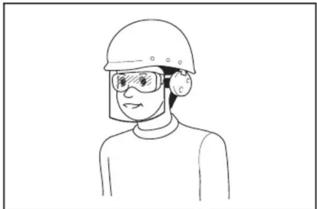
- Always wear protective goggles to protect your eyes from injury when using power tools. The goggles must comply with ANSI Z87.1 in the USA, EN 166 in Europe, or AS/NZS 1336 in Australia/New Zealand. In Australia/New Zealand, it is legally required to wear a face shield to protect your face, too.
natural_image
Line drawing of a person wearing a helmet and safety goggles (no text or symbols)
It is an employer's responsibility to enforce the use of appropriate safety protective equipments by the tool operators and by other persons in the immediate working area.
- The risks to others shall be assessed by the operator.
-
Be careful with tools without workpiece contact as they can be fired unintentionally and injure operator and/or bystander.
-
Ensure tool is always safely engaged on the workpiece and cannot slip.
- Wear hearing protection to protect your ears against exhaust noise and head protection. Also wear light but not loose clothing. Sleeves should be buttoned or rolled up. No necktie should be worn.
Operating hazards
- Hold the tool correctly: be ready to counteract normal or sudden movements such as recoil.
- Maintain a balanced body position and secure footing.
- Appropriate safety glasses shall be used and appropriate gloves and protective clothing are recommended.
- Appropriate hearing protection shall be worn.
- Use the correct energy supply as directed in the instruction manual.
- Do not use the tool on moving platforms or back of trucks. Sudden movement of the platform may lose control of the tool and cause injury.
- Always assume that the tool contains fasteners.
- Do not rush the job or force the tool. Handle the tool carefully.
- Watch your footing and maintain your balance with the tool. Make sure there is no one below when working in high locations, and secure the air hose to prevent danger if there is sudden jerking or catching.
- On rooftops and other high locations, drive fasteners as you move forward. It is easy to lose your footing if you drive fasteners while inching backward. When driving fasteners against perpendicular surface, work from the top to the bottom. You can perform driving operations with less fatigue by doing so.
- A fastener will be bent or the tool can become jammed if you mistakenly drive fastener on top of another fastener or strike a knot in the wood. The fastener may be thrown and hit someone, or the tool itself can react dangerously. Place the fasteners with care.
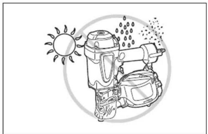
- Do not leave the loaded tool or the air compressor under pressure for a long time out in the sun. Be sure that dust, sand, chips and foreign matter will not enter the tool in the place where you leave it setting.
- Never attempt to drive fasteners from both the inside and outside at the same time. Fasteners may rip through and/or fly off, presenting a grave danger.
Repetitive motions hazards
- When using a tool for long periods, the operator may experience discomfort in the hands, arms, shoulders, neck, or other parts of the body.
- While using a tool, the operator should adopt a suitable but ergonomic posture. Maintain secure footing and avoid awkward or off-balanced postures.
-
If the operator experiences symptoms such as persistent or recurring discomfort, pain, throbbing, aching, tingling, numbness, burning sensation, or stiffness, do not ignore these warning signs. The operator should consult a qualified health professional regarding overall activities.
-
The continuous use of the tool may cause repetitive stain injury due to recoil produced by the tool.
-
To avoid repetitive strain injury, the operator should not overreach or use excessive force. Additionally, the operator should take a rest when feeling fatigue.
-
Conduct a risk assessment regarding repetitive motion hazards. It should focus on muscular-skeletal disorders and be preferentially based on the assumption that decreasing fatigue during work is effective in reducing disorders.
Accessory and consumable hazards
-
Disconnect the energy supply to the tool, such as air or gas or battery as applicable, before changing/replacing accessories such as workpiece contact, or making any adjustments.
-
Use only the sizes and types of accessories that are provided by the manufacturer.
-
Use only lubricants recommended in this manual.
Workplace hazards
-
Slips, trips and falls are major causes of workplace injury. Be aware of slippery surfaces caused by use of the tool and also of trip hazards caused by the air line hose.
-
Proceed with additional care in unfamiliar surroundings. Hidden hazards may exist, such as electricity or other utility lines.
-
This tool is not intended for use in potentially explosive atmospheres and is not insulated from coming into contact with electric power.
-
Make sure there are no electrical cables, gas pipes etc. that could cause a hazard if damaged by use of the tool.
-
Keep work area clean and well lit. Cluttered or dark areas invite accidents.
-
There may be local regulations concerning noise which must be complied with by keeping noise levels within prescribed limits. In certain cases, shutters should be used to contain noise.
Dust and exhaust hazards
-
Always check your surroundings. The air exhausted from the tool may blow dust or objects and hit operator and/or bystanders.
-
Direct the exhaust so as to minimize disturbance of dust in a dust filled environment.
-
If dust or objects are emitted in the work area, reduce the emission as much as possible to reduce the health hazards and risk of injury.
Noise hazards
-
Unprotected exposure to high noise levels can cause permanent, disabling, hearing loss and other problems such as tinnitus (ringing, buzzing, whistling or humming in the ears).
-
Conduct a risk assessment regarding noise hazards in the work area and implement appropriate controls for these hazards.
-
Appropriate controls to reduce the risk may include actions such as damping materials to prevent workpieces from "ringing".
-
Use appropriate hearing protection.
-
Operate and maintain the tool as recommended in these instructions, to prevent an unnecessary increase in noise levels.
-
Take noise reduction measures, for example placing workpieces on sound damping supports.
Vibration hazards
- The vibration emission during operation depends on the gripping force, the contact pressure force, the working direction, the adjustment of energy supply, the workpiece, the workpiece support. Conduct a risk assessment regarding vibration hazards and implement appropriate controls for these hazards.
- Exposure to vibration can cause disabling damage to the nerves and blood supply of the hands and arms.
- Wear warm clothing when working in cold conditions, keep your hands warm and dry.
- If you experience numbness, tingling, pain or whitening of the skin in your fingers or hands, seek medical advice from a qualified occupational health professional regarding overall activities.
- Operate and maintain the tool as recommended in these instructions, to prevent an unnecessary increase in vibration levels.
- Hold the tool with a light, but safe, grip because the risk from vibration is generally greater when the grip force is higher.
-
Compressed air can cause severe injury.
-
Always shut off air supply, and disconnect tool from air supply when not in use.
-
Always disconnect the tool from the compressed air supply before changing accessories, making adjustments and/or repairs, when moving away from an operating area to a different area.
-
Keep fingers away from trigger when not operating the tool and when moving from one operating position to another.
-
Never direct compressed air at yourself or anyone else.
-
Whipping hoses can cause severe injury. Always check for damaged or loose hoses or fittings.
-
Never carry a pneumatic tool by its hose.
-
Never drag a pneumatic tool by its hose.
-
When using pneumatic tools, do not exceed the maximum operating pressure ps max.
-
Pneumatic tools should only be powered by compressed air at the lowest pressure required for the work process to reduce noise and vibration, and minimize wear.
- Using oxygen or combustible gases for operating pneumatic tools creates a fire and explosion hazard.
- Be careful when using pneumatic tools as the tool could become cold, affecting grip and control.
Additional warnings for tools with contact actuation capability
- Do not rest your finger on the trigger when picking up the tool, moving between operating areas and positions or walking, as resting finger on trigger can lead to inadvertent operation. For tools with selective actuation, always check the tool before use to ascertain the correct mode is selected.
- This tool has either selective actuation for contact actuation or continuous contact actuation by actuation mode selectors or is a contact actuation or continuous actuation contact tool and has been marked with the symbol above. Its intended uses are for production applications such as pallets, furniture, manufactured housing, upholstery and sheathing.
- If using this tool in selective actuation mode, always ensure it is in the correct actuation setting.
- Do not use this tool in contact actuation for applications such as closing boxes or crates and fitting transportation safety systems on trailers and lorries.
- Be careful when changing from one driving location to another.
Safety devices
- Make sure all safety systems are in working order before operation. The tool must not operate if only the trigger is pulled or if only the contact arm is pressed against the wood. It must work only when both actions are performed. Test for possible faulty operation with fasteners unloaded and the pusher in fully pulled position.
- Securing the trigger in the ON position is very dangerous. Never attempt to fasten the trigger.
- Do not attempt to keep the contact element depressed with tape or wire. Death or serious injury may occur.
- Always check contact element as instructed in this manual. Fasteners may be driven accidentally if the safety mechanism is not working correctly.
Service
- Perform cleaning and maintenance right after finishing the job. Keep the tool in tip-top condition. Lubricate moving parts to prevent rusting and minimize friction-related wear. Wipe off all dust from the parts.
- Ask Makita authorized service center for periodical inspection of the tool.
- To maintain product SAFETY and RELIABILITY, maintenance and repairs should be performed by Makita Authorized Service Centers, always using Makita replacement parts.
- Follow local regulations when disposing of the tool.
SAVE THESE INSTRUCTIONS.
⚠ WARNING: DO NOT let comfort or familiarity with product (gained from repeated use) replace strict adherence to safety rules for the subject product. MISUSE or failure to follow the safety rules stated in this instruction manual may cause serious personal injury.
PARTS DESCRIPTION (Fig. 1)
INSTALLATION
Selecting compressor
line
| Nailing frequency (times/min) | Compressor air output per minute (L/min) |
| ----------------------------- | ---------------------------------------- |
| 40 | 83 |
| 60 | 79 |
| 60 | 68 |
| 60 | 59 |
The air compressor must comply with the requirements of EN60335-2-34.
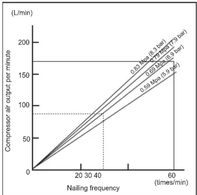
Select a compressor that has ample pressure and air output to assure cost-efficient operation. The graph shows the relation between nailing frequency, applicable pressure and compressor air output.
Thus, for example, if nailing takes place at a rate of approximately 30 times per minute at a compression of 0.69 MPa (6.9 bar), a compressor with an air output over 80 L/minute is required.
Pressure regulators must be used to limit air pressure to the rated pressure of the tool where air supply pressure exceeds the tool's rated pressure. Failure to do so may result in serious injury to tool operator or persons in the vicinity.
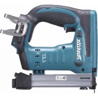
Selecting air hose (Fig. 2)
Use an air hose as large and as short as possible to assure continuous, efficient nailing operation. With an air pressure of 0.49 MPa (4.9 bar), an air hose with an internal diameter of over 6.5 mm and a length of less than 20 m is recommended when the interval between each nailing is 0.5 seconds. Air supply hoses shall have a minimum working pressure rating of 1.03 MPa (10.3 bar) or 150 percent of the maximum pressure produced in the system whichever is higher.
CAUTION:
- Low air output of the compressor, or a long or smaller diameter air hose in relation to the nailing frequency may cause a decrease in the driving capability of the tool.
Lubrication
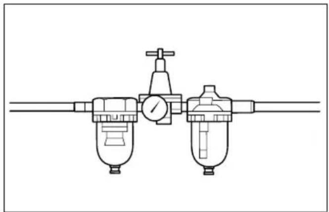
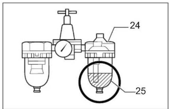
To insure maximum performance, install an air set (oiler, regulator, air filter) as close as possible to the tool. Adjust the oiler so that one drop of oil will be provided for every 30 nails. (Fig. 3)
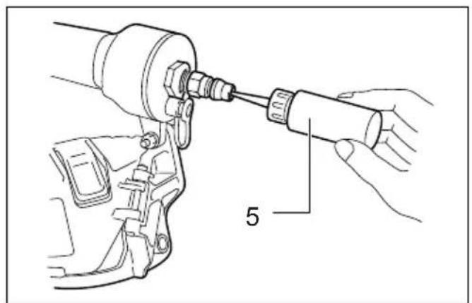
When an air set is not used, oil the tool with pneumatic tool oil by placing 2 (two) or 3 (three) drops into the air fitting. This should be done before and after use. For proper lubrication, the tool must be fired a couple of times after pneumatic tool oil is introduced. (Fig. 4)
FUNCTIONAL DESCRIPTION
CAUTION:
- Always disconnect the air hose before adjusting or checking function on the tool.
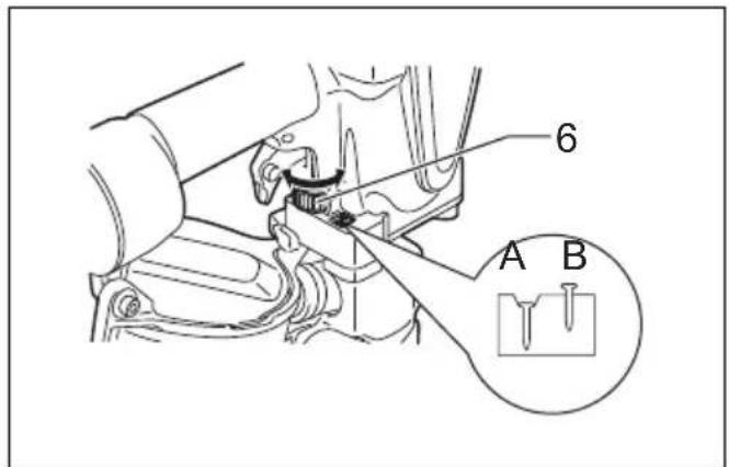
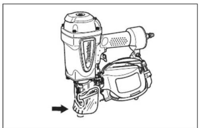
Adjusting depth of nailing (Fig. 5)
To adjust the depth of nailing, turn the adjuster. The depth of nailing is the deepest when the adjuster is turned fully in the A direction shown in the figure. It will become shallower as the adjuster is turned in the B direction. If nails cannot be driven deep enough even when the adjuster is turned fully in the A direction, increase the air pressure. If nails are driven too deep even when the adjuster is turned fully in the B direction, decrease the air pressure. Generally speaking, the tool service life will be longer when the tool is used with lower air pressure and the adjuster set to a lower depth of nail driving.
CAUTION:
• Always disconnect the hose before adjusting the depth of nailing.
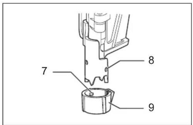
Use the nose adapter (Fig. 6)
CAUTION:
- Always disconnect the hose before installing or removing the nose adapter.
If you like to protect the surface of workpiece, attach the nose adapter of contact element.
When nailing workpieces with easily-marred surfaces, use the nose adapter. To attach the nose adapter to the contact element, press it onto the contact element until the protrusion in three places inside the nose adapter fit in three holes in the contact element.
ASSEMBLY
CAUTION:
• Always disconnect the air hose before carrying out any work on the tool.
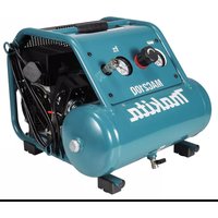
Loading nailer
Select nails suitable for your work. Depress the latch lever and open the door. And then open the magazine cap. (Fig. 7)
Lift and turn the coil support plate so that the arrow with nail size indicated on the coil support plate will point to the corresponding graduation increment marked on the magazine. If the tool is operated with the coil support plate set to the wrong step, poor nail feed or malfunction of the tool may result. (Fig. 8)
Place the nail coil over the coil support plate. Uncoil enough nails to reach the feed claw. Place the first nail in the driver channel and the second nail in the feed claw. Place other uncoiled nails on feeder body. Close the magazine cap after checking to see that the nail coil is set properly in the magazine. (Fig. 9)
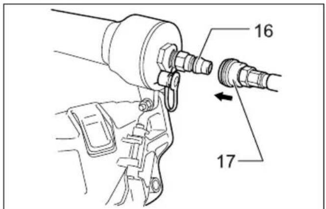
Connecting air hose (Fig. 10)
Slip the air socket of the air hose onto the air fitting on the nailer. Be sure that the air socket locks firmly into position when installed onto the air fitting. A hose coupling must be installed on or near the tool in such a way that the pressure reservoir will discharge at the time the air supply coupling is disconnected.
OPERATION
CAUTION:
- Make sure all safety systems are in working order before operation.
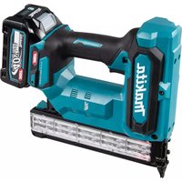
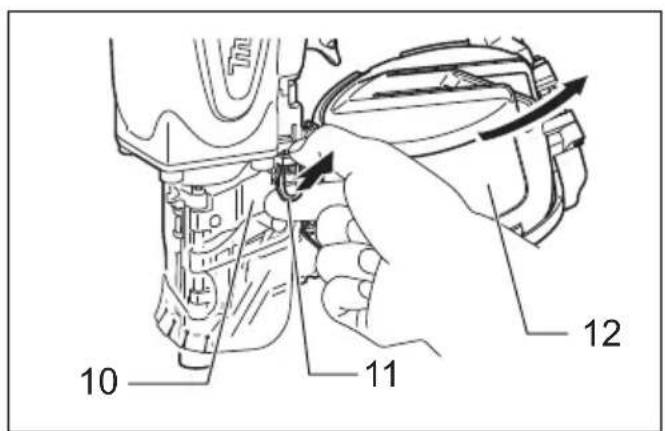
Selecting the operation mode
CAUTION:
- Always make sure that the change lever is properly set to the position for the desired nailing mode before nailing.
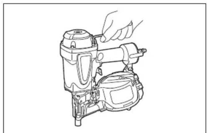
This tool is equipped with the change lever. You can select either the single sequential actuation mode or the contact actuation mode with it. (Fig. 11)
Single sequential actuation mode:
You can drive one nail by one sequential operation. Select this mode when driving a nail carefully and accurately.
To choose this mode, set the change lever to the position.
You can drive nails repetitively by placing the contact element with the trigger held.
To choose this mode, set the change lever to the position.
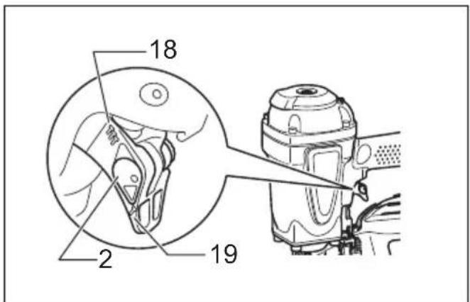
Checking proper action before operation
Before operation, always check following points.
- Make sure that the tool does not operate only by connecting the air hose.
- Make sure that the tool does not operate only by pulling the trigger.
- Make sure that the tool does not operate only by placing the contact element against the workpiece without pulling the trigger.
- In single sequential actuation mode, make sure that the tool does not operate when pulling the trigger first and then placing the contact element against the workpiece.
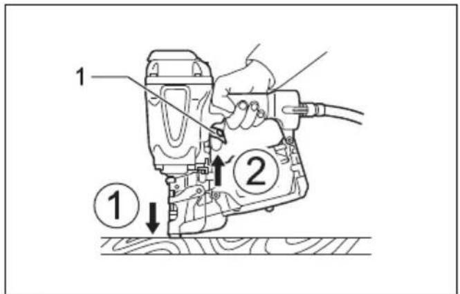
Single sequential actuation
Place the contact element against the workpiece and pull the trigger fully.
After nailing, release the contact element, and then release the trigger. (Fig. 12)
CAUTION:
- Do not place the contact element against the workpiece with excessive force. Also, pull the trigger fully and hold it on for 1-2 seconds after nailing. Even in the "Single sequential actuation" mode, half-pulled trigger causes an unexpected nailing, when the contact element recontacts the workpiece.
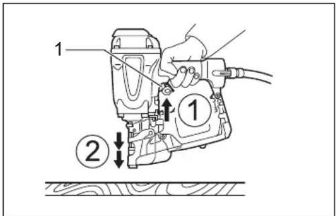
Pull the trigger first and then place the contact element against the workpiece. (Fig. 13)
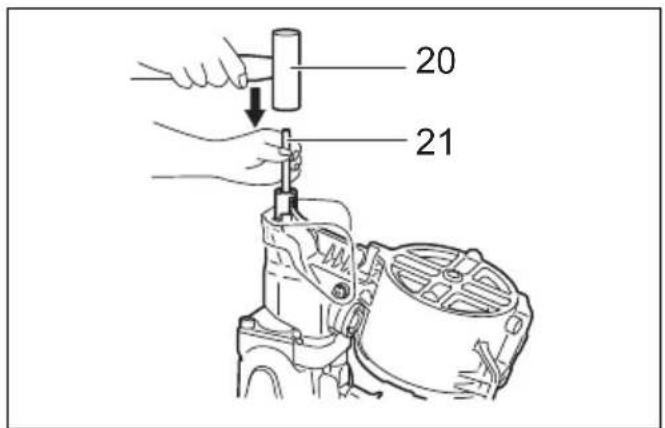
Jammed nailer (Fig. 14)
CAUTION:
• Always disconnect the air hose and remove the nails from the magazine before cleaning a jam.
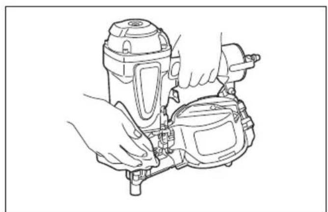
When the nailer becomes jammed, do as follows:
Open the magazine cap and remove the nail coil. Insert a small rod or the like into the ejection port and tap it with a hammer to drive out the nail jamming from the ejection port. Reset the nail coil and close the magazine cap.
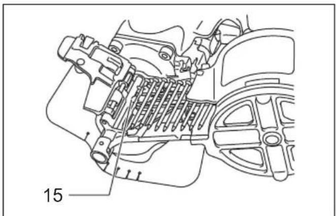
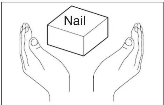
Nails
Handle nail coils and their box carefully. If the nail coils have been handled roughly, they may be out of shape or their connector breaks, causing poor nail feed. (Fig. 15)
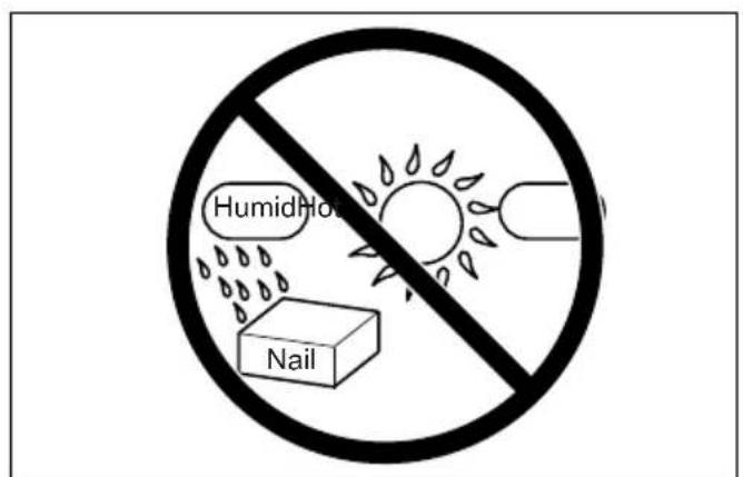
Avoid storing nails in a very humid or hot place or place exposed to direct sunlight. (Fig. 16)
MAINTENANCE
CAUTION:
- Always disconnect the air hose from the tool before attempting to perform inspection or maintenance.
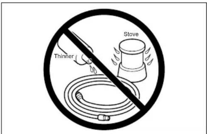
- Never use gasoline, benzine, thinner, alcohol or the like. Discoloration, deformation or cracks may result.
Maintenance of nailer
Always check the tool for its overall condition and loose screws before operation. Tighten as required. (Fig. 17)
With tool disconnected, make daily inspection to assure free movement of the contact element and trigger. Do not use tool if the contact element or trigger sticks or binds. (Fig. 18)
When the tool is not to be used for an extended period of time, lubricate the tool using pneumatic tool oil and store the tool in a safe place. Avoid exposure to direct sunlight and/or humid or hot environment. (Fig. 19 & 20)
Maintenance of compressor, air set and air hose
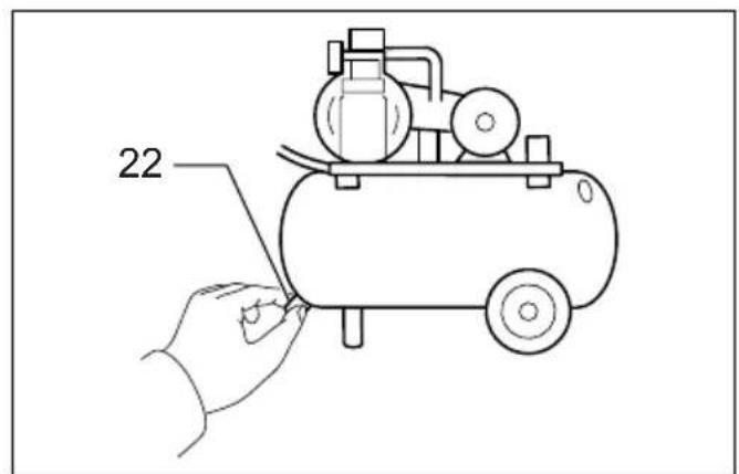
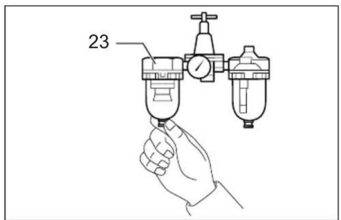
After operation, always drain the compressor tank and the air filter. If moisture is allowed to enter the tool, it may result in poor performance and possible tool failure.
(Fig. 21 & 22)
Check regularly to see if there is sufficient pneumatic oil in the oiler of the air set. Failure to maintain sufficient lubrication will cause O-rings to wear quickly. (Fig. 23)
Keep the air hose away from heat (over 60^ C, over 140^ F), away from chemicals (thinner, strong acids or alkalis). Also, route the hose away from obstacles which it may become dangerously caught on during operation. Hoses must also be directed away from sharp edges and areas which may lead to damage or abrasion to the hose. (Fig. 24)
To maintain product SAFETY and RELIABILITY, repairs, any other maintenance or adjustment should be performed by Makita Authorized Service Centers, always using Makita replacement parts.
OPTIONAL ACCESSORIES
CAUTION:
• These accessories or attachments are recommended for use with your Makita tool specified in this manual. The use of any other accessories or attachments might present a risk of injury to persons. Only use accessory or attachment for its stated purpose.
If you need any assistance for more details regarding these accessories, ask your local Makita Service Center.
- Nails
- Air hoses
NOTE:
- Some items in the list may be included in the tool package as standard accessories. They may differ from country to country.
ENG905-1
Noise
The typical A-weighted noise level determined according to EN ISO 11148-13:
Sound pressure level ( L_pA ): 98.3 dB (A)
Sound power level ( L_WA ): 98.9 dB (A)
Uncertainty (K): 2.5 dB (A)
Wear ear protection
ENG904-2
Vibration
The vibration total value determined according to EN ISO 11148-13:
Vibration emission (a _h ): 2.52 m/s ^2
Uncertainty (K): 1.26 m/s ^4
ENG901-1
- The declared vibration emission value has been measured in accordance with the standard test method and may be used for comparing one tool with another.
- The declared vibration emission value may also be used in a preliminary assessment of exposure.
WARNING:
- The vibration emission during actual use of the power tool can differ from the declared emission value depending on the ways in which the tool is used.
- Be sure to identify safety measures to protect the operator that are based on an estimation of exposure in the actual conditions of use (taking account of all parts of the operating cycle such as the times when the tool is switched off and when it is running idle in addition to the trigger time).
For European countries only
The EC declaration of conformity is included as Annex A to this instruction manual.
Descriptif
natural_image
Line drawing of a person wearing a hard hat and safety goggles (no text or symbols)
natural_image
Line drawing of a person wearing a hard hat and safety goggles (no text or symbols)
natural_image
Line drawing of a person wearing a hard hat and safety goggles (no text or symbols)
line
| Freqenza di chiodatura (volte/min.) | Uscita aria compressore al minuto (L/min.) |
|---|---|
| 0 | 0 |
| 203040 | 83 Mpa (8.3 bar) |
| 203040 | 79 Mpa (7.9 bar) |
| 203040 | 69 Mpa (6.9 bar) |
| 60 | 59 Mpa (5.9 bar) |
The chart displays a linear relationship between the frequency of chiodatura and the compressore compressore for each pressure level. The data points are annotated with their respective pressure values in Mpa and bar length. There is no additional data series present in the chart.
natural_image
Line drawing of a person wearing a hard hat and safety goggles (no text or symbols)
OPTIONELE ACCESSOIRES
LET OP:
natural_image
Line drawing of a person wearing a hard hat and safety goggles (no text or symbols)
natural_image
Line drawing of a person wearing a hard hat and safety goggles (no text or symbols)
natural_image
Line drawing of a person wearing a helmet and safety goggles (no text or symbols)
natural_image
Line drawing of a person wearing a hard hat and safety goggles (no text or symbols)
natural_image
Line drawing of a person wearing a hard hat and safety goggles (no text or symbols)
natural_image
Line drawing of a person wearing a hard hat and safety goggles (no text or symbols)
natural_image
Line drawing of a person wearing a hard hat and safety goggles (no text or symbols)
natural_image
Line drawing of a person wearing a hard hat and safety goggles (no text or symbols)
natural_image
Line drawing of a person wearing a hard hat and safety goggles (no text or symbols)
natural_image
Line drawing of a person wearing a helmet and safety goggles (no text or symbols)
WYPOSAŻENIE DODATKOWE

PRZESTROGA:
natural_image
Line drawing of a person wearing a helmet and safety goggles (no text or symbols)
TYTO POKYNY USCHOVEJTE.
VOLITELNÉ PŘÍSLUŠENSTVÍ
⚠ UPOZORNĚNÍ:
natural_image
Line drawing of a person wearing a hard hat and safety goggles (no text or symbols)
TIETO POKYNY USCHOVAJTE.
natural_image
Line drawing of a person wearing a hard hat and safety goggles (no text or symbols)
natural_image
Line drawing of a person wearing a hard hat and safety goggles (no text or symbols)
natural_image
Line drawing of a person wearing a hard hat and safety goggles (no text or symbols)