FN001G - Electric stapler MAKITA - Free user manual and instructions
Find the device manual for free FN001G MAKITA in PDF.
| Brand | Makita |
| Model | FN001G |
| Product type | Cordless electric stapler |
| Intended use | Interior and furniture work |
| Dimensions (L × W × H, without hook) | 265 mm × 86 mm × 243 mm |
| Net weight (depending on battery) | 2.6 kg to 3.8 kg |
| Rated voltage | DC 36 V - 40 V max. |
| Nail size | 18 Ga × 15, 20, 25, 30, 35, 40 mm |
| Magazine capacity | 100 nails |
| Compatible batteries | BL4020*, BL4025*, BL4040, BL4040F, BL4050F, BL4080F |
| Compatible chargers | DC40RA, DC40RB, DC40RC, DC40WA, BCC01, BCC02 |
| Sound pressure level (LpA) | 81 dB(A) |
| Sound power level (LWA) | 92 dB(A) |
| Vibrations (ah) | 2.5 m/s² or less |
| Depth adjustment | Up to 2.5 mm |
| Lighting | Integrated LED light |
| Safety mechanism | Trigger lock button, contact element, dry-fire lockout |
| Included accessories | Nozzle adapter, hex key, suspension hook |
| Maintenance | Regular cleaning, repair by Makita authorized center |
Frequently Asked Questions - FN001G MAKITA
User questions about FN001G MAKITA
0 question about this device. Answer the ones you know or ask your own.
Ask a new question about this device
Download the instructions for your Electric stapler in PDF format for free! Find your manual FN001G - MAKITA and take your electronic device back in hand. On this page are published all the documents necessary for the use of your device. FN001G by MAKITA.
USER MANUAL FN001G MAKITA
natural_image
Technical line drawing of a mechanical assembly with internal components (no text or symbols)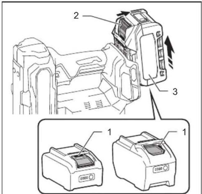
text_image
Technical diagram showing three labeled components of a device with directional arrows indicating movement or assembly.Fig.1
text_image
B A 1Fig.5
text_image
Diagram showing a device with control panel and battery, labeled with components 1 and 2Fig.2
text_image
1 2 3Fig.6
text_image
Fig.3 1 2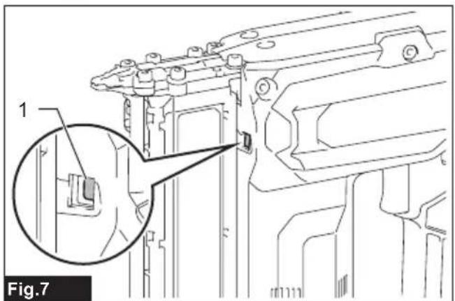
natural_image
Technical line drawing of a mechanical component with an inset magnified detail (no text or symbols)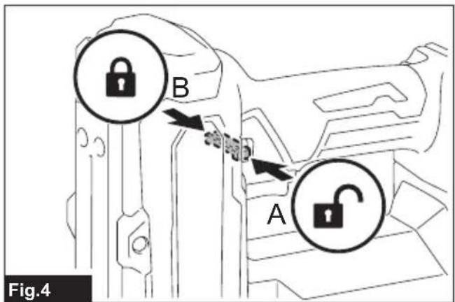
text_image
B A Fig.4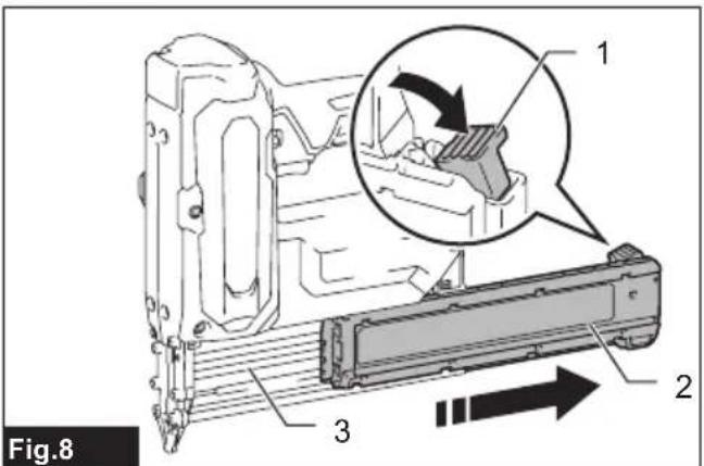
text_image
Fig.8 1 2 3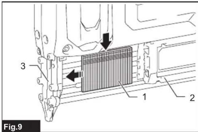
text_image
Fig.9 1 2 3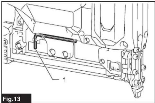
text_image
1 Fig.13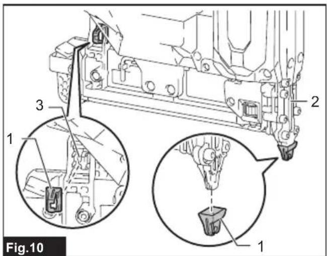
text_image
Fig.10 1 2 3 1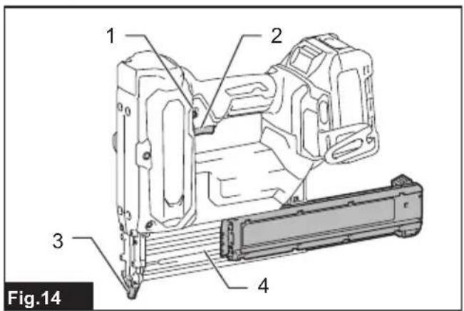
text_image
Fig.14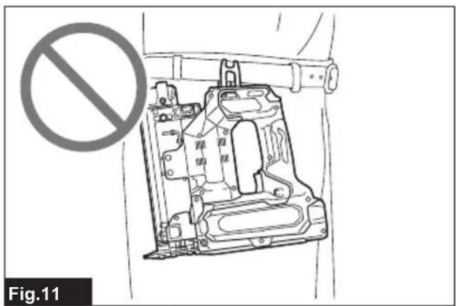
natural_image
Technical line drawing of a mechanical assembly with a no-smoking symbol (no text or labels present)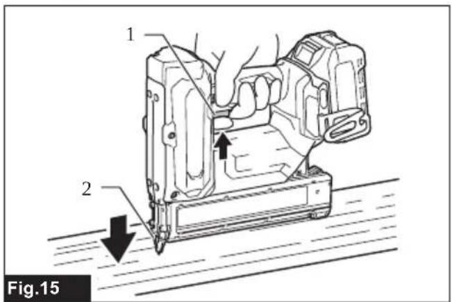
text_image
1 2 Fig.15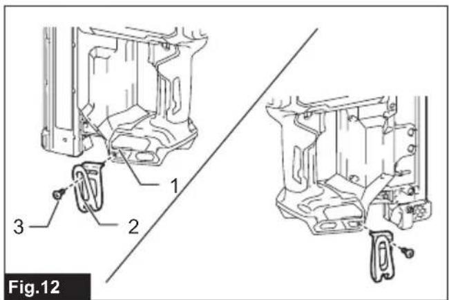
text_image
Fig.12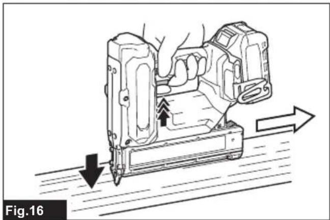
natural_image
Technical line drawing of a mechanical assembly with directional arrows indicating movement (no text or symbols)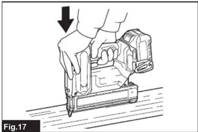
natural_image
Illustration of hands using a power tool to press or install a device, with a downward arrow indicating compression (no text or symbols present)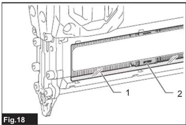
text_image
Fig.18 1 2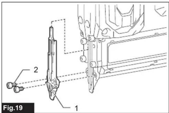
text_image
Fig.19 1 2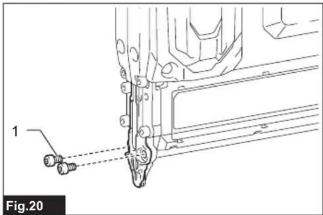
natural_image
Technical line drawing of a mechanical assembly with labeled component '1' and dashed alignment lines (no text or symbols beyond labels)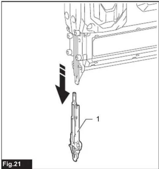
text_image
Fig.21 1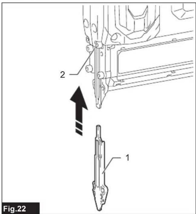
text_image
Fig.22 1 2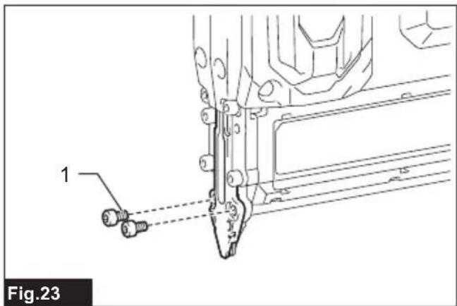
text_image
1 Fig.23SPECIFICATIONS
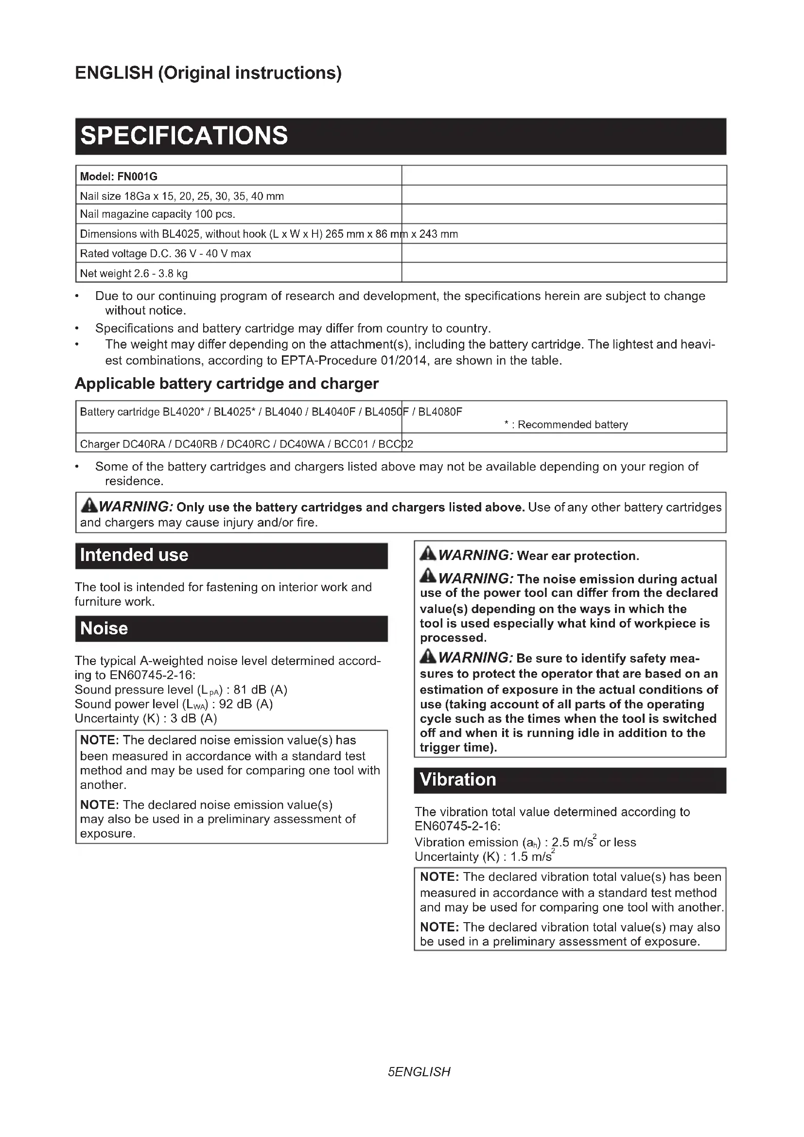
| Model: FN001G | |
| Nail size 18Ga x 15, 20, 25, 30, 35, 40 mm | |
| Nail magazine capacity 100 pcs. | |
| Dimensions with BL4025, without hook (L x W x H) 265 mm x 86 mm x 243 mm | |
| Rated voltage D.C. 36 V - 40 V max | |
| Net weight 2.6 - 3.8 kg | |
- Due to our continuing program of research and development, the specifications herein are subject to change without notice.
- Specifications and battery cartridge may differ from country to country.
- The weight may differ depending on the attachment(s), including the battery cartridge. The lightest and heaviest combinations, according to EPTA-Procedure 01/2014, are shown in the table.
Applicable battery cartridge and charger
| Battery cartridge BL4020* / BL4025* / BL4040 / BL4040F / BL4050F / BL4080F | *: Recommended battery |
| Charger DC40RA / DC40RB / DC40RC / DC40WA / BCC01 / BCC02 |
- Some of the battery cartridges and chargers listed above may not be available depending on your region of residence.
WARNING: Only use the battery cartridges and chargers listed above. Use of any other battery cartridges and chargers may cause injury and/or fire.
Intended use
The tool is intended for fastening on interior work and furniture work.
Noise
The typical A-weighted noise level determined according to EN60745-2-16: Sound pressure level ( L_pA ): 81 dB (A) Sound power level ( L_WA ): 92 dB (A) Uncertainty (K): 3 dB (A)
NOTE: The declared noise emission value(s) has been measured in accordance with a standard test method and may be used for comparing one tool with another.
NOTE: The declared noise emission value(s) may also be used in a preliminary assessment of exposure.
WARNING: Wear ear protection.
WARNING: The noise emission during actual use of the power tool can differ from the declared value(s) depending on the ways in which the tool is used especially what kind of workpiece is processed.
WARNING: Be sure to identify safety measures to protect the operator that are based on an estimation of exposure in the actual conditions of use (taking account of all parts of the operating cycle such as the times when the tool is switched off and when it is running idle in addition to the trigger time).
Vibration
The vibration total value determined according to EN60745-2-16:
Vibration emission ( a_h ): 2.5 m/s ^2 or less
Uncertainty (K) : 1.5 m/s ^4
NOTE: The declared vibration total value(s) has been measured in accordance with a standard test method and may be used for comparing one tool with another.
NOTE: The declared vibration total value(s) may also be used in a preliminary assessment of exposure.
WARNING: The vibration emission during actual use of the power tool can differ from the declared value(s) depending on the ways in which the tool is used especially what kind of workpiece is processed.
WARNING: Be sure to identify safety measures to protect the operator that are based on an estimation of exposure in the actual conditions of use (taking account of all parts of the operating cycle such as the times when the tool is switched off and when it is running idle in addition to the trigger time).
For European countries only
The Declarations of conformity are included in Annex A to this instruction manual.
WARNING Read all safety warnings, instructions, illustrations and specifications provided with this power tool. Failure to follow all instructions listed below may result in electric shock, fire and/or serious injury.
Save all warnings and instructions for future reference.
The term "power tool" in the warnings refers to your mains-operated (corded) power tool or battery-operated (cordless) power tool.
- Always assume that the tool contains fasteners. Careless handling of the nailer can result in unexpected firing of fasteners and personal injury.
- Do not point the tool towards yourself or anyone nearby. Unexpected triggering will discharge the fastener causing an injury.
- Do not actuate the tool unless the tool is placed firmly against the workpiece. If the tool is not in contact with the workpiece, the fastener may be deflected away from your target.
- Disconnect the tool from the power source when the fastener jams in the tool. While removing a jammed fastener, the nailer may be accidentally activated if it is plugged in.
- Use caution while removing a jammed fastener. The mechanism may be under compression and the fastener may be forcefully discharged while attempting to free a jammed condition.
-
Do not use this nailer for fastening electrical cables. It is not designed for electric cable installation and may damage the insulation of electric cables thereby causing electric shock or fire hazards.
-
Keep hands and feet away from the ejection
port area.
- Follow instruction for lubricating and changing accessories.
- Always remove the battery cartridge before loading the fasteners, adjustment, inspection, maintenance or after operation is over.
- Make sure no one is nearby before operation. Never attempt to drive fasteners from both the inside and outside of wall at the same time. Fasteners may rip through and/or fly off, presenting a grave danger.
- Watch your footing and maintain your balance with the tool. Make sure there is no one below when working in high locations.
- Never use fastener driving tools marked with the symbol "Do not use on scaffoldings, ladders" for specific application for example:
- when changing one driving location to another involves the use of scaffoldings, stairs, ladders, or ladder alike constructions, e.g. roof laths;
• closing boxes or crates;
- fitting transportation safety systems e.g. on vehicles and wagons.
-
Check walls, ceilings, floors, roofing and the like carefully to avoid possible electrical shock, gas leakage, explosions, etc. caused by stapling into live wires, conduits or gas pipes.
-
Use only fasteners specified in this manual. The use of any other fasteners may cause malfunction of the tool.
-
Do not tamper with the tool or attempt to use it for other than driving fasteners.
-
Do not operate the tool without fasteners. It shortens the service life of the tool.
-
Stop driving operations immediately if you notice something wrong or out of the ordinary with the tool.
-
Never fasten into any materials which may allow the fastener to puncture and fly through as a projectile.
-
Never actuate the switch trigger and contact element at the same time until you are prepared to fasten workpieces. Allow the workpiece to depress the contact element. Never defeat its purpose by securing the contact element back or by depressing it by hand.
-
Never tamper with the contact element. Check the contact element frequently for proper operations.
- Always remove fasteners from the tool when not in use.
SAVE THESE INSTRUCTIONS.
WARNING: DO NOT let comfort or familiarity with product (gained from repeated use) replace strict adherence to safety rules for the subject product. MISUSE or failure to follow the safety rules stated in this instruction manual may cause serious personal injury.
Important safety instructions for battery cartridge
- Before using battery cartridge, read all instructions and cautionary markings on (1) battery charger, (2) battery, and (3) product using battery.
- Do not disassemble or tamper with the battery cartridge. It may result in a fire, excessive heat, or explosion.
- If operating time has become excessively shorter, stop operating immediately. It may result in a risk of overheating, possible burns and even an explosion.
-
If electrolyte gets into your eyes, rinse them out with clear water and seek medical attention right away. It may result in loss of your eyesight.
-
Do not short the battery cartridge:
(1) Do not touch the terminals with any conductive material.
(2) Avoid storing battery cartridge in a container with other metal objects such as nails, coins, etc.
(3) Do not expose battery cartridge to water or rain.
A battery short can cause a large current flow, overheating, possible burns and even a breakdown.
-
Do not store and use the tool and battery cartridge in locations where the temperature may reach or exceed 50 °C (122 °F).
-
Do not incinerate the battery cartridge even if it is severely damaged or is completely worn out. The battery cartridge can explode in a fire.
-
Do not nail, cut, crush, throw, drop the battery cartridge, or hit against a hard object to the battery cartridge. Such conduct may result in a fire, excessive heat, or explosion.
-
Do not use a damaged battery.
-
The contained lithium-ion batteries are subject to the Dangerous Goods Legislation requirements.
For commercial transports e.g. by third parties, forwarding agents, special requirement on packaging and labeling must be observed.
For preparation of the item being shipped, consulting an expert for hazardous material is required.
Please also observe possibly more detailed national regulations.
Tape or mask off open contacts and pack up the battery in such a manner that it cannot move around in the packaging.
-
When disposing the battery cartridge, remove it from the tool and dispose of it in a safe place. Follow your local regulations relating to disposal of battery.
-
Use the batteries only with the products specified by Makita. Installing the batteries to non-compliant products may result in a fire, excessive heat, explosion, or leak of electrolyte.
-
If the tool is not used for a long period of time, the battery must be removed from the tool.
-
During and after use, the battery cartridge may
take on heat which can cause burns or low temperature burns. Pay attention to the handling of hot battery cartridges.
-
Do not touch the terminal of the tool immediately after use as it may get hot enough to cause burns.
-
Do not allow chips, dust, or soil stuck into the terminals, holes, and grooves of the battery cartridge. It may cause heating, catching fire, burst and malfunction of the tool or battery cartridge, resulting in burns or personal injury.
-
Unless the tool supports the use near high-voltage electrical power lines, do not use the battery cartridge near high-voltage electrical power lines. It may result in a malfunction or breakdown of the tool or battery cartridge.
-
Keep the battery away from children.
SAVE THESE INSTRUCTIONS.

CAUTION: Only use genuine Makita batteries.
Use of non-genuine Makita batteries, or batteries that have been altered, may result in the battery bursting causing fires, personal injury and damage. It will also void the Makita warranty for the Makita tool and charger.
Tips for maintaining maximum battery life
- Charge the battery cartridge before completely discharged. Always stop tool operation and charge the battery cartridge when you notice less tool power.
- Never recharge a fully charged battery cartridge. Overcharging shortens the battery service life.
- Charge the battery cartridge with room temperature at 10 °C - 40 °C (50 °F - 104 °F). Let a hot battery cartridge cool down before charging it.
- When not using the battery cartridge, remove it from the tool or the charger.
- Charge the battery cartridge if you do not use it for a long period (more than six months).
FUNCTIONAL DESCRIPTION

CAUTION: Always be sure that the tool is itched off and the battery cartridge is removed fore adjusting or checking function on the tool.
Installing or removing battery cartridge
⚠️CAUTION: Always switch off the tool before installing or removing of the battery cartridge.
⚠️CAUTION: Hold the tool and the battery cartridge firmly when installing or removing battery cartridge. Failure to hold the tool and the battery cartridge firmly may cause them to slip off your hands and result in damage to the tool and battery cartridge and a personal injury.
To install the battery cartridge, align the tongue on the battery cartridge with the groove in the housing and slip it into place. Insert it all the way until it locks in place with a little click. If you can see the red indicator as shown in the figure, it is not locked completely.
To remove the battery cartridge, slide it from the tool while sliding the button on the front of the cartridge.
▶ Fig.1: 1. Red indicator 2. Button 3. Battery cartridge
⚠CAUTION: Always install the battery cartridge fully until the red indicator cannot be seen. If not, it may accidentally fall out of the tool, causing injury to you or someone around you.
⚠️CAUTION: Do not install the battery cartridge forcibly. If the cartridge does not slide in easily, it is not being inserted correctly.
Tool / battery protection system
The tool is equipped with a tool/battery protection system. This system automatically cuts off power to the motor to extend tool and battery life. The tool will automatically stop during operation if the tool or battery is placed under one of the following conditions:
Overload protection
When the tool/battery is operated in a manner that causes it to draw an abnormally high current, the tool automatically stops without any indication. In this situation, turn the tool off and stop the application that caused the tool to become overloaded. Then turn the tool on to restart.
Overheat protection
When the tool/battery is overheated, the tool stops automatically. In this situation, let the tool/battery cool before turning the tool on again.
Overdischarge protection
When the battery capacity is not enough, the tool stops automatically. In this case, remove the battery from the tool and charge the battery.
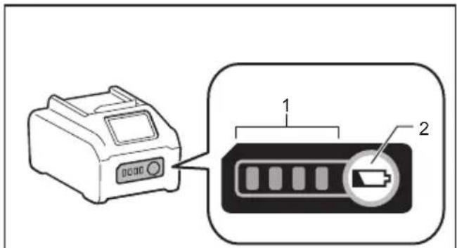
Indicating the remaining battery capacity
Press the check button on the battery cartridge to indicate the remaining battery capacity. The indicator lamps light up for a few seconds.
▶ Fig.2: 1. Indicator lamps 2. Check button
| Indicator lamps Remaining | capacity | ||
| Lighted Off | Blinking | ||
| 75% to 100% | |||
| 50% to 75% | |||
| 25% to 50% | |||
| 0% to 25% | |||
| Charge the battery. | |||
| The battery may have malfunctioned. | |||
NOTE: Depending on the conditions of use and the ambient temperature, the indication may differ slightly from the actual capacity.
NOTE: The first (far left) indicator lamp will blink when the battery protection system works.
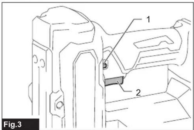
Trigger-lock button
CAUTION: Before installing the battery cartridge into the tool, always check to see that the switch trigger actuates properly and returns to the "OFF" position when released.
CAUTION: When not operating the tool, depress the trigger-lock button from B side to lock the switch trigger in the OFF position.
▶ Fig.3: 1. Trigger-lock button 2. Switch trigger
▶ Fig.4
To prevent the switch trigger from accidentally pulled, the trigger-lock button is provided. To pull the switch trigger, depress the trigger-lock button from A side.
After use, always press in the trigger-lock button from B side.
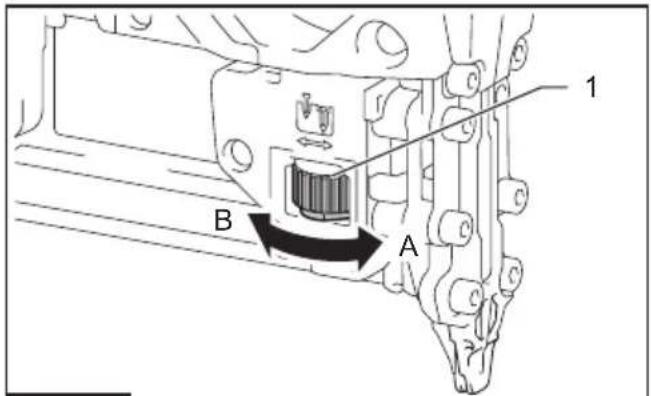
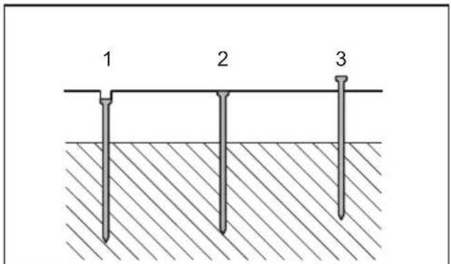
Adjusting the depth of nailing
WARNING: Always make sure that your fingers are not placed on the switch trigger or the contact element and the battery cartridge is removed before adjusting the depth of nailing.
Depth of nailing can be adjusted by turning the adjuster on the tool. A nail drives deeper as you turn the adjuster in the A direction shown in the figure, and shallower in the B direction, within a range of up to 2.5 mm.
▶ Fig.5: 1. Adjuster
▶ Fig.6: 1. Too deep 2. Right depth 3. Too shallow
CAUTION: Do not look in the light or see the source of light directly.
Pull the switch trigger or actuate the contact element to light up the lamp. The lamp remains lit for up to 60 seconds while pulling the switch trigger or actuating the contact element. The lamp goes out approximately 10 seconds after releasing the switch trigger and the contact element.
▶ Fig.7: 1. Lamp
NOTICE: Use a dry cloth to wipe the dirt o the of the lamp. Be careful not to scratch the lens of lamp, or it may lower the illumination.
NOTICE: Even in the lamp lights up when the battery power residual gets small, nailer may not re nails. In this case, charge the battery cartridge.
NOTICE: When the tool is overheated, the light ashes. In this case, release the switch trigger and contact element, and then cool down the tool/battery before operating again.
NOTICE: The lamp starts blinking if the nailer detects an error during driving the nail. In this case, bring the nailer to a Factory Service Center.
CAUTION: Always make sure that your fingers are not placed on the switch trigger or the contact element and the battery cartridge is removed before carrying out any work on the nailer.
CAUTION: Always make sure that your fingers are not placed on the trigger and the battery cartridge is removed before loading nails.
CAUTION: Do not abruptly slide the slide door of the nailer loaded with nails. Accidentally dropping nails especially when working in high places may cause personal injuries.
CAUTION: Load nails in the correct direction. Loading in wrong direction may cause premature wear and tear of the driver and damage of the other parts.
CAUTION: Do not use deformed nail strips.
Use nails speci ed in this manual. Using nails other than those speci ed may cause nail jamming and breakage of the nailer.
- Press the lock lever and open the slide door of the magazine.
▶ Fig.8: 1. Lock lever 2. Slide door 3. Magazine
- Set a nail strip so that the nail tips touch the bottom of the magazine and slide the nail strip toward the driver guide.
▶ Fig.9: 1. Nails 2. Slide door 3. Driver guide
- Return the slide door to the original position until the lock lever locks it.
To remove the nails, press the lock lever and slide the slide door. Take out nails from the magazine.
CAUTION: Always make sure that your fingers are not placed on the switch trigger or the contact element and the battery cartridge is removed before installing the nose adapter.
lens When ring nails on the material with easily-marred surfaces, use the nose adapter. Put the adapter onto the pointed end of the driver guide.
You can store the nose adapter in the holder at the back end of the magazine to keep it from being lost.
▶ Fig.10: 1. Nose adapter 2. Driver guide 3. Holder
CAUTION: When installing the hook, always secure it with the screw firmly. If not, the hook
may come o from the tool and result in the personal injury.
CAUTION: Use the hanging/mounting parts for their intended purposes only. Using for unintended purpose may cause accident or personal injury.
CAUTION: Do not hang the hook from the
waist belt. Dropping the nailer, which is caused by the hook accidentally coming out of place, may cause unintentional ring and result in personal injuries.
▶ Fig.11
The hook is convenient for temporarily hanging the tool.
This can be installed on either side of the tool.
To install the hook, insert it into a groove in the tool housing on either side and then secure it with a screw.
To remove, loosen the screw and then take it out.
▶ Fig.12: 1. Groove 2. Hook 3. Screw
When not in use, store the hex wrench as shown in the gure to keep it from being lost.
▶ Fig.13: 1. Hex wrench
WARNING: Make sure all safety systems are working order before operation. Failure to do may cause personal injuries.
Fig.14: 1. Trigger-lock button 2. Switch trigger 3. Contact element 4. Magazine
Test safety systems as follows for possible fault before
operation.
- Unload nails from the tool and keep the magazine opened.
- Install the battery cartridge and release the trigger lock.
- Pull the switch trigger without touching the contact element against the material.
- Touch the contact element against the material without pulling the switch trigger.
If the tool operates in the case of 3 or 4 above, the safety systems are faulty. Stop using the tool immediately and ask your local service center.
Driving nails
WARNING: Do not use this nailer for fastening electrical cables. It is not designed for electric cable installation and may damage the insulation of electric cables thereby causing electric shock or fire hazards.
WARNING: Continue to place the contact element firmly on the material until the nail is driven completely. Unintentional firing may cause personal injuries.
⚠️CAUTION: Hold the tool firmly during operation.
- Release the trigger lock.
- Place flat the contact element on the material.
- Pull the switch trigger fully to drive a nail.
- To drive the next nail, release your finger from the switch trigger once, and then repeat the step 2 and 3 above.
▶ Fig.15: 1. Switch trigger 2. Contact element
You can also drive the nails when dragging the tool to the next area with the contact element pressed against the material and pulling the switch trigger.
▶ Fig.16
If the head of the nail remains above the workpiece surface, drive the nail while holding the nailer head firmly against the workpiece.
▶ Fig.17
NOTE: If the head of the nail still remains above the workpiece even you hold the nail head, the material may not be suitable for the nailer. Continuing to use the nailer on such material may result in a damage to the driver of the nailer and/or nailer jamming.
Anti dry fire mechanism
WARNING: Always make sure that your fingers are not placed on the switch trigger or the contact element and the battery cartridge is removed before loading the nailer.
When the number of remaining nail strips in the magazine is empty, the switch trigger can no longer be pulled. At this time, insert a new nail strip in the magazine. The switch trigger can be pulled again.
Checking remaining nails
You can check the amount of remaining nails through the sight window.
The red indicator moves toward firing opening as the amount of remaining nails becomes smaller.
▶ Fig.18: 1. Sight window 2. Indicator
Removing jammed nails
WARNING: Always make sure that the trigger is released, and the battery cartridge and nails are removed before removing jammed nails.
⚠️ CAUTION: Do not remove the jammed nails with bare hands. The nail may jump out of the magazine and cause an injury.
Remove the hex bolts on the driver guide using the hex wrench.
Take the jammed nails from the nail guide groove with a slotted screwdriver.
Secure the driver guide with the hex bolts.
▶ Fig.19: 1. Driver guide 2. Hex bolt
NOTE: After securing the driver guide, always make sure that it actuates properly. If not, remove hex bolts and install the driver guide again.
MAINTENANCE
CAUTION: Always be sure that the tool is switched off and the battery cartridge is removed before attempting to perform inspection or maintenance.
NOTICE: Never use gasoline, benzine, thinner, alcohol or the like. Discoloration, deformation or cracks may result.
To maintain product SAFETY and RELIABILITY, repairs, any other maintenance or adjustment should be performed by Makita Authorized or Factory Service Centers, always using Makita replacement parts.
Replacing driver guide
Optional accessory
Replace the standard-equipped driver guide with the optional driver guide better suited for fastening chamfer strip.
- Remove the hex bolts on the driver guide using the hex wrench.
▶ Fig.20: 1. Hex bolt
- Pull off the standard-equipped driver guide downward.
▶ Fig.21: 1. Standard-equipped driver guide
- Install the optional driver guide by pushing it upward into the guide slot.
▶ Fig.22: 1. Optional driver guide 2. Guide slot
- Secure the optional driver guide with the hex bolts.
▶ Fig.23: 1. Hex bolt
OPTIONAL ACCESSORIES
⚠️CAUTION: These accessories or attachments are recommended for use with your Makita tool specified in this manual. The use of any other accessories or attachments might present a risk of injury to persons. Only use accessory or attachment for its stated purpose.
If you need any assistance for more details regarding these accessories, ask your local Makita Service Center.
- Nails
- Driver guide (for fastening chamfer strip)
• Makita genuine battery and charger
NOTE: Some items in the list may be included in the tool package as standard accessories. They may differ from country to country.
SPÉCIFICATIONS
▶ Abb.13: 1. Inbusschlüssel
BETRIEB
VEILIGHEIDSWAAR- SCHUWINGEN
▶ Fig.20: 1. Inbusbout
▶ Fig.23: 1. Inbusbout
OPTIONELE ACCESSOIRES
▶ Fig.13: 1. Chave hexagonal
OPERAÇÃO
▶ Fig.20: 1. Perno hexagonal
▶ Fig.23: 1. Perno hexagonal
ACESSÓRIOS OPCIONAIS
▶ Eik.13: 1. Κλειδί άλεν