LLCDI18022L - Drill RYOBI - Free user manual and instructions
Find the device manual for free LLCDI18022L RYOBI in PDF.
User questions about LLCDI18022L RYOBI
0 question about this device. Answer the ones you know or ask your own.
Ask a new question about this device
Download the instructions for your Drill in PDF format for free! Find your manual LLCDI18022L - RYOBI and take your electronic device back in hand. On this page are published all the documents necessary for the use of your device. LLCDI18022L by RYOBI.
USER MANUAL LLCDI18022L RYOBI
natural_image
Line drawing of a handheld electric drill press (no text or symbols)
text_image
Technical diagram of a handheld electric drill with numbered parts labeled for identification.Fig. 1
text_image
23 24 6 10 8 9 10 Fig. 2
text_image
13 14 25 15 Fig. 4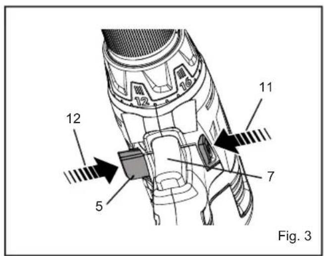
text_image
12 11 5 7 Fig. 3
text_image
LO 2 HI 16 4 17 Fig. 5
text_image
18 19 20 3 20 18 19 Fig. 6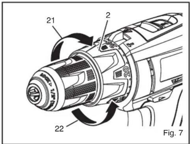
text_image
21 2 20 22 Fig. 7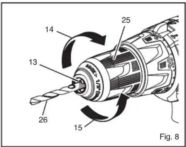
text_image
14 25 13 26 15 Fig. 8Important! It is essential that you read the instructions in this manual before operating this machine.
■ Wear ear protectors. Exposure to noise can cause hearing loss.
■ Use auxiliar y handle(s), if supplied with the tool. Loss of control can cause personal injury.
- Hold power tool by insulated gripping surfaces, when performing an operation where the cutting accessory may contact hidden wiring. Cutting accessory contacting a «live» wire may make exposed metal parts of the power tool «live» and could give the operator an electric shock.
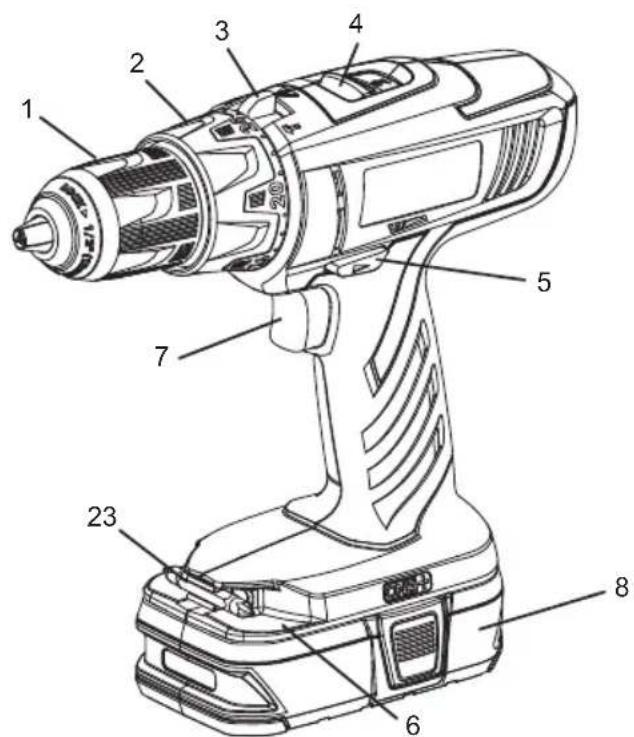
DESCRIPTION
- Keyless chuck
- Torque adjustment ring
- Quick mode selector
- Two-speed gear train
- Rotation selector (forward/reverse/center lock)
- Bit storage
- Switch trigger
- Battery pack (Not included)
- Latches
- Depress latches to release battery pack
- Reverse
- Forward
- Chuck jaws
- Lock (tighten)
- Unlock (release)
- Low speed
- High speed
- Drive mode
- Drill mode
- Hammer mode
- To increase torque
- To decrease torque
- Bit
- Bit holder
- Chuck sleeve
- Drill bit
SPECIFICATIONS
| Voltage | --- |
| Chuck | 2-13 mm |
| Switch | Variable speed |
| No load speed (Drill mode): | |
| -Lo speed | 0-400 min ^-1 |
| -Hi speed | 0-1550 min ^-1 |
| Hammer speed (Blows per minute): | |
| -Lo speed | 0-5200 min ^-1 |
| -Hi speed | 0-20150 min ^-1 |
| Max. torque | 40 Nm |
| Weight (not incl. battery pack) | 1.38 Kg |
| MODEL | COMPATIBLE BATTERY PACK | COMPATIBLE CHARGER |
| LLCDI1802 | BPL-1820BPL-1815 | BCL-1800BCS618BCL1418BCL14181HBCL14183H |
| BPP-1815BPP-1815MBPP-1817BPP-1817M | BC-1815SBC-1800BCL-1800BCS618BCL1418BCL14181HBCL14183H |
English
OPERATION

RNING
Do not allow familiarity with products to make you careless. Remember that a careless fr action of a second is sufficient to inflict serious injury.

RNING
Always wear safety goggles or safety glasses with side shields when operating products. Failure to do so could result in objects being thrown into your eyes, resulting in possible serious injury.

WARNING
Do not use any attachments or accessories not recommended by the manufacturer of this product. The use of attachments or accessories not recommended can result in serious personal injury.
APPLICATIONS
You may use this product for the purposes listed below:
■ Drilling in all types of wood products (lumber, plywood, panelling, composition board, and hard board)
■ Drilling in ceramics, plastics, fiberglass, and laminates
■ Drilling in metals
■ Driving screws
■ Hammer drilling in concrete, brick, or other masonry
This product will accept R YOBI One+ 18 V lithium-ion battery packs and R YOBI One+ 18 V nickel-cadmium battery packs.
BATTERY PROTECTION FEATURES
RYOBI 18 V lithium-ion batteries are designed with features that protect the lithium-ion cells and maximize battery life. Under some operating conditions, these built-in features may cause the battery y and the tool it is powering to act differently from nickel-cadmium batteries. During some applications, the battery y electronics may signal the battery y to shut down, and cause the tool to stop running. To reset the battery y and tool, release the trigger and resume normal operation.
NOTE: To prevent further shut down of the battery, avoid forcing the tool.
If releasing the trigger does not reset the battery and tool, the battery pack is depleted. If depleted, the battery pack will begin charging when placed on the lithium-ion charger.
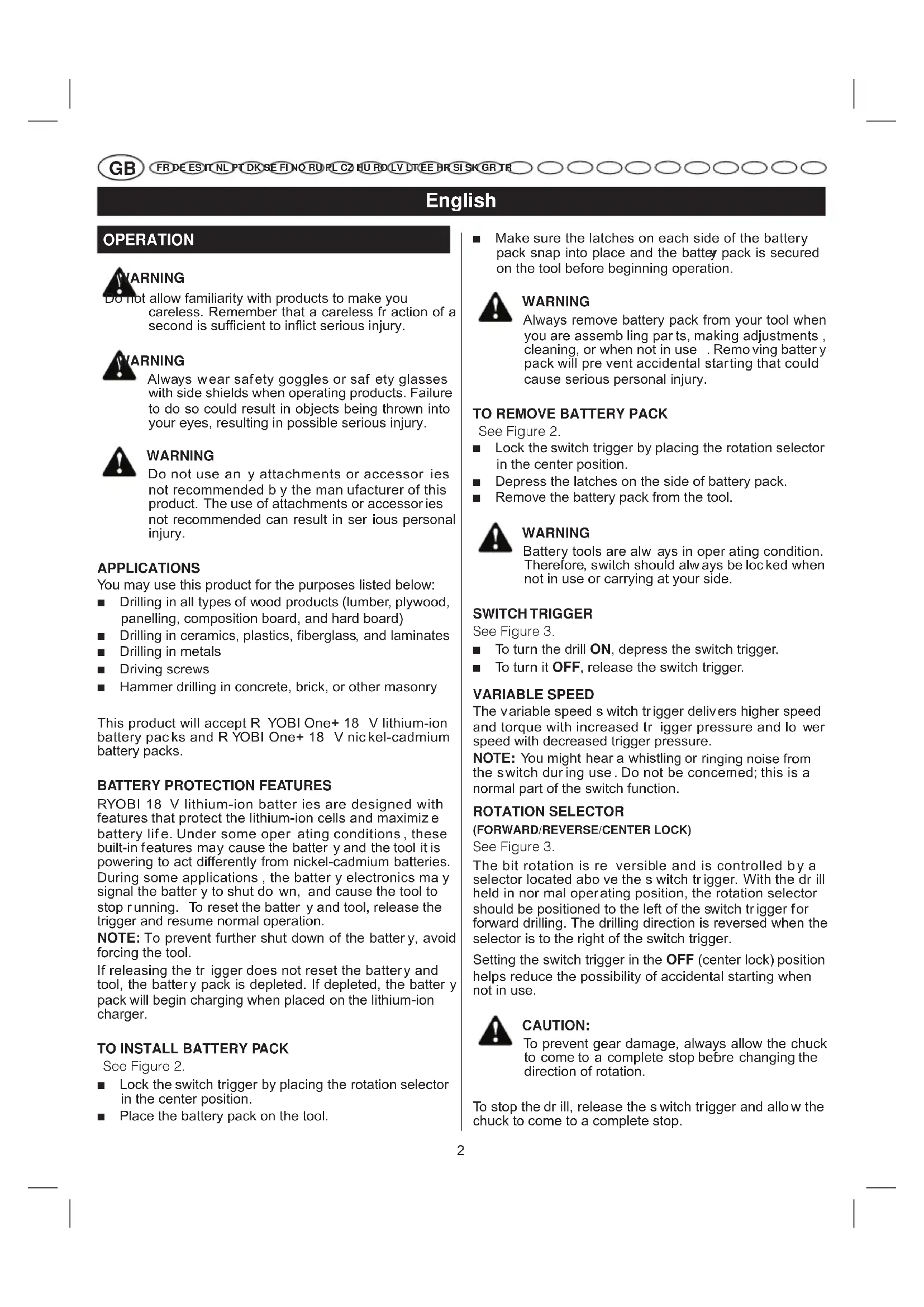
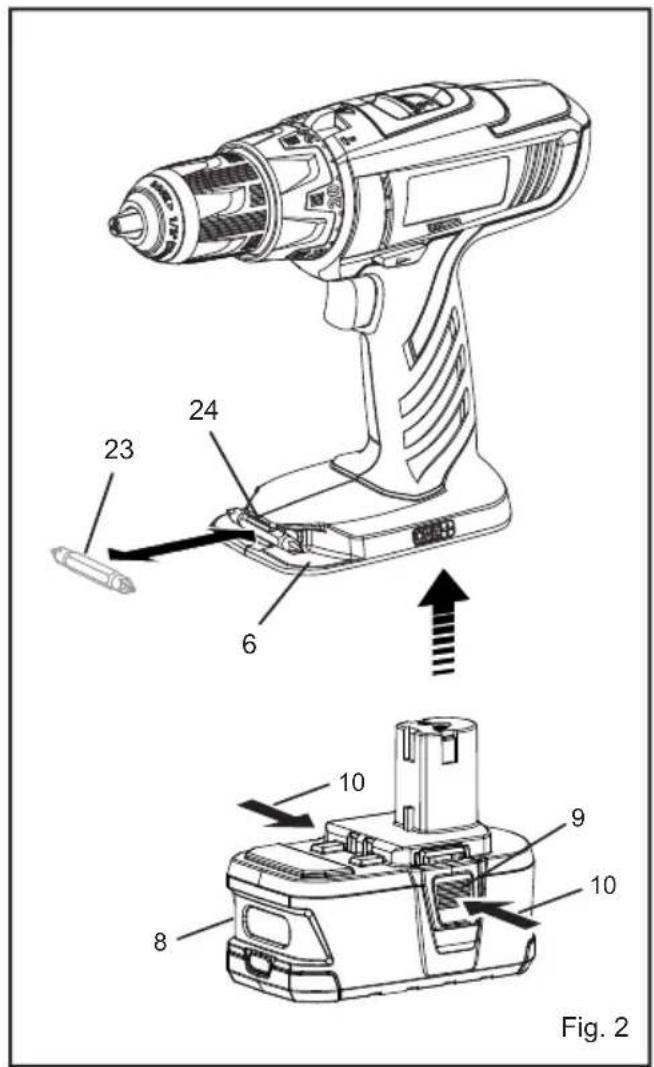
TO INSTALL BATTERY PACK
See Figure 2.
■ Lock the switch trigger by placing the rotation selector in the center position.
■ Place the battery pack on the tool.
■ Make sure the latches on each side of the battery pack snap into place and the battery pack is secured on the tool before beginning operation.

WARNING
Always remove battery pack from your tool when you are assemb ling parts, making adjustments, cleaning, or when not in use. Removing battery y pack will pre vent accidental starting that could cause serious personal injury.
TO REMOVE BATTERY PACK
See Figure 2.
■ Lock the switch trigger by placing the rotation selector in the center position.
■ Depress the latches on the side of battery pack.
■ Remove the battery pack from the tool.

WARNING
Battery tools are always in operating condition. Therefore, switch should always be locked when not in use or carrying at your side.
SWITCH TRIGGER
See Figure 3.
■ To turn the drill ON, depress the switch trigger.
■ To turn it OFF, release the switch trigger.
VARIABLE SPEED
The variable speed s witch trigger delivers higher speed and torque with increased trigger pressure and lo wer speed with decreased trigger pressure.
NOTE: You might hear a whistling or ringing noise from the switch during use. Do not be concerned; this is a normal part of the switch function.
ROTATION SELECTOR
(FORWARD/REVERSE/CENTER LOCK)
See Figure 3.
The bit rotation is reversible and is controlled by a selector located abo ve the s witch trigger. With the drill held in nor mal operating position, the rotation selector should be positioned to the left of the switch trigger for forward drilling. The drilling direction is reversed when the selector is to the right of the switch trigger.
Setting the switch trigger in the OFF (center lock) position helps reduce the possibility of accidental starting when not in use.

CAUTION:
To prevent gear damage, always allow the chuck to come to a complete stop before changing the direction of rotation.
To stop the dr ill, release the switch trigger and allow the chuck to come to a complete stop.
English
OPERATION
NOTE: The drill will not run unless the rotation selector is pushed fully to the left or right.
Avoid running the drill at low speeds for extended periods of time. Running at low speeds under constant usage may cause the drill to become a verheated. If this occurs cool the drill by running it without a load and at full speed.
The inter nal spindle loc k allows the user single-handed control of chuck adjustments and bit changes. Squeezing the chuck body stops the chuc k jaws from turning. For bit changes and chuc k adjustments, squeeze the chuc k body and turn.
KEYLESS CHUCK
See Figure 4.
The dr ill has a k eyless chuck to tighten or release dr bits in the chuc k jaws. The arrows on the chuc k indicate which direction to rotate the chuck body in order to LOCK (tighten) or UNLOCK (release) the drill bit.

WARNING
Do not hold the chuck with one hand and use the power of the drill to tighten the chuck jaws on the drill bit. The chuck body could slip in y our hand, or your hand could slip and come in contact with the rotating drill bit. This could cause an accident resulting in serious personal injury.
TWO-SPEED GEAR TRAIN (HI-LO)
See Figure 5.
The drill has a two-speed gear train designed for drilling or driving at LO (1) or HI (2) speeds. A slide switch is
located on top of the drill to select either LO (1) or HI (2) speed. When using drill in the LO (1) speed range, speed will decrease and unit will have more power and torque. When using drill in the HI (2) speed range, speed will increase and unit will have less power and torque. Use LO (1) speed for high power and torque applications and HI (2) speed for fast drilling or driving applications.
NOTE: If you have difficulty changing from one gear range to the other, turn the chuck by hand until the gears engage.

CAUTION:
Never change gears while the tool is running. Failure to obey this caution could result in serious damage to the drill.
QUICK MODE SELECTOR
See Figure 6.
The Quick Mode Selector allo ws you to quick kly switch from drill mode to drive mode.
In general, dr ill mode should be used f or dr illing and other heavy duty applications. Dr ive mode should be used for driving screws. Hammer mode should be used for impact drilling.
SELECTING DRIVE OR DRILL SETTING
See Figure 5-6.
Using the chart belo w, choose correct speed and mode the type of bit, fastener, and material you will be using.
■ Choose your APPLICATION
■ Choose the correct SPEED: (1/LOW or 2/HIGH)
■ Choose the correct MODE: (DRIVE, DRILL, OR HAMMER)
| 1. APPLICATION | 2. SPEED | 3. MODE |
| Lag screws up to 9.5 mm dia. by 38.1 mm longHole saw up to 50.8 mmSpade bits up to 38.1 mmDrill bits up to 12.7 mmDrilling into metalConcrete screws | 1/LOW | DRILL MODE(TORQUE ADJUSMENT NOT ACTIVE)[6238] |
| 2/HIGH | ||
| Drill bits up to 6.4 mmDeck or wood screws up to 76.2 mm longSelf tapping screws | 1/LOW | DRIVE MODE[SAGA] |
| Deck or wood screws up to 76.2 mm longSmall screws or delicate work that requires more control | 2/HIGH | |
| Masonry bit up to 12.7 mm | 1/LOW | HAMMER MODE(TORQUE ADJUSMENT NOT ACTIVE) |
| 2/HIGH |
English
OPERATION
TORQUE ADJUSTMENT
See Figure 7.
When using the drill-driver for various driving applications, it becomes necessary to increase or decrease the torque in order to help pre vent the possibility of damaging screw heads, threads, workpiece, etc. In general, torque intensity should correspond to the screw diameter. If the torque is too high or the screws too small, the screws may be damaged or broken.
The torque is adjusted by rotating the torque adjustment ring. The torque is greater when the torque adjusting is set on a higher setting. The torque is less when the torque adjustment ring is set on a lower setting.
The proper setting depends on the type of material and the size of screw you are using.
BIT STORAGE
See Figure 2.
When not in use, bits provided with the drill can be placed in the storage areas located on the base of the drill.
INSTALLING BITS
See Figure 8.
■ Lock the switch trigger by placing the rotation selector in the center position.
■ Open or close the chuck jaws to a point where the opening is slightly larger than the bit size you intend to use. Also, raise the front of the drill slightly to keep the bit from falling out of the chuck jaws.
■ Insert the drill bit.
■ Tighten the chuck jaws on the drill bit.

WARNING:
Make sure to insert the dr ill bit str aight into the chuck jaws. Do not inset the drill bit into the chuck jaws at an angle then tighten. This could cause the drill bit to be thrown from the drill, resulting in possib le serious personal injur y or damage to the chuck.
NOTE: Rotate the chuck body in the direction of the arrow mar ked LOCK to tighten the chuck jaws. Do not use a wrench to tighten or loosen the chuck jaws.
REMOVING BITS
See Figure 8.
■ Lock the switch trigger by placing the rotation selector in the center position.
■ Open the chuck jaws.
NOTE: Rotate the chuc k body in the direction of the arrow marked UNLOCK to loosen the chuck jaws. Do not use a wrench to tighten or loosen the chuck jaws.
■ Remove the drill bit.
DRILLING
■ Check the rotation selector for the correct setting (forward or reverse).
- Secure the material to be drilled in a vise or with clamps to keep it from turning as the drill bit rotates.
■ Hold the drill firmly and place the bit at the point to be drilled.
English
OPERATION
■ Depress the switch trigger to start the drill.
■ Move the drill bit into the workpiece, applying only enough pressure to keep the bit cutting. Do not force the drill or apply side pressure to elongate a hole. Let the tool do the work.

WARNING:
repared f or binding at bit breakthrough.
When these situations occur, drill has a tendency to grab and kick opposite to the direction of rotation and could cause loss of control when breaking through material. If not prepared, this loss of control can result in possible serious injury.
■ When drilling hard, smooth surf aces, use a center punch to mar k the desired hole location. This will prevent the drill bit from slipping off-center as the hole is started.
■ When drilling metals, use a light oil on the drill bit to keep it from overheating. The oil will prolong the life of the bit and increase the drilling action.
If the bit jams in the workpiece or if the drill stalls, stop the tool immediately. Remove the bit from the workpiece and determine the reason for jamming.
NOTE: This drill has an electric brake. When the switch trigger is released, the chuck stops turning. When the brake is functioning properly, sparks will be visible through the vent slots on the housing. This is normal and is the action of the brake.
MAINTENANCE

WARNING
When servicing, use only identical RYOBI replacement parts. Use of any other pas may create a hazard or cause product damage.
Avoid using solvents when cleaning plastic parts. Most plastics are susceptible to damage from various types of commercial solvents and may be damaged by their use. Use clean cloths to remove dirt, dust, oil, grease, etc.

WARNING
Do not at an y time let br ake fluids, gasoline, petroleumbased products, penetrating oils, etc., come in contact with plastic parts. Chemicals can damage, weaken or destro y plastic which ma y result in serious personal injury.
Do not abuse power tools. Abusive practices can damage tool as well as workpiece.

WARNING
Do not attempt to modify this tool or create accessories not recommended for use with this tool. Any such alteration or modification is misuse and could result in a hazardous condition leading to possible serious personal injury.
ENVIRONMENTAL PROTECTION
Recycle raw materials instead of disposing as waste. The machine, accessories and packaging should be sorted for environmental-friendly recycling.
SYMBOLS

Safety Alert
V
Volts
min-1
Revolutions or reciprocations per minute
...
Direct current

CE Conformity

Please read the instructions carefully before starting the machine.

Recycle unwanted

Waste electrical products should not be disposed of with household waste. Please recycle where facilities exist. Check with your Local Authority or retailer for recycling advice.
Français
RÈGLES PARTICULIÈRES DE SÉCURITÉ
| MODEL | BATTERI (delete -ENHED) | KOMPATIBEL OPLADER (medfølger ikke) |
| LLCDI1802 | BPL-1820 BPL-1815 | BCL-1800 BCS618 BCL1418 BCL14181H BCL14183H |
| BPP-1815 BPP-1815M BPP-1817 BPP-1817M | BCL-1800 BCS618 BC-1815S BC-1800 BCL1418 BCL14181H BCL14183H |
SÅDAN G∅R DU

ADVARSEL
(FOROVER, BAKOVER, MIDTSTILLINGSLÅS)
Se Fig. 3.
Greutate (fără accumulator) 1,38 Kg
Română
SPECIFICATII
| MODEL | ACUMULATOR(neinclus) | ÎNCĂRCĂTORCOMPATIBIL(neinclus) |
| LLCDI1802 | BPL-1820BPL-1815 | BCL-1800BCS618BCL1418BCL14181HBCL14183H |
| BPP-1815BPP-1815MBPP-1817BPP-1817M | BCL-1800BCS618BC-1815SBC-1800BCL1418BCL14181HBCL14183H |
OPERAREA

AVERTISMENT
C. Alegeti MODUL corect: (ANGRENARE, GÄURIRE SAU PERFORARE)
Română
OPERAREA
POSEBNA SIGURNOSNA PRAVILA
(SOL/SAĞ/ORTA KİLIT)
Bakınız Şekil 3.
GB Conformance to technical regulations
FR Conformité aux normes techniques
All Ryobi products are guaranteed against man ufacturing defects and defective parts for a period of twenty four (24) months from the date stated on the original invoice drawn up by the retailer and given to the end user. Deterioration caused by normal wear and tear, unauthorised or improper use or maintenance, or overload are excluded from this guarantee as are accessories such as battery packs, light bulbs, blades, fittings, bags, etc. In the event of malfunction during the warranty period, please take the NON-DISMANTLED product, along with the proof of purchase, to your retailer or nearest Authorised Ryobi Service Centre.
This warranty in no way affects your legal rights concerning defective products.
FR
GARANTIE - CONDITIONS
The vibration emission level given in this information sheet has been measured in accordance with a standardised test given in EN 60745 and may be used to compare one tool with another. It may be used for a preliminary assessment of exposure. The declared vibration emission level represents the main applications of the tool. However if the tool is used for different applications, with different accessories or poorly maintained, the vibration emission may differ. This may significantly increase the exposure level over the total working period.
An estimation of the level of exposure to vibration should also take into account the times when the tool is switched of f or when it is running but not actually doing the job. This may signif cantly reduce the exposure level over the total working period. Identify additional safety measures to protect the operator from the ef fects of vibration such as: maintain the tool and the accessories, keep the hands warm, organisation of work patterns.
FR
AVERTISSEMENT
DECLARATION OF CONFORMITY
We declare under our sole responsibility that this product is in conformity with the following standards or standardized documents.
2011/65/EU, 2006/42/EC, 2004/108/EC, EN 60745-1:2009+A11:2010, EN 60745-2-1:2010, EN 60745-2-2:2010, EN 55014-1:2006+A1:2009+
A2:2011, EN 55014-2:1997+A2:2008.
Sound pressure level (K=3 dB(A)) 88.5 dB(A) Sound power level (K=3 dB(A)) 99.5 dB(A)
Weighted root mean
The vibration total values(triax vector sum) determined according to EN60745:
Drilling into metal, vibration emission value ah, D=1.4 m/s² (Uncertainty K=1.5 m/s²)
Impact drilling into concrete, vibration emission value ah, ID=15.0 m/s ^2
(Uncertainty K = 1.5 m/s ^2 )
Screwdriving without impact, vibration emission value ah = 0.7 m/s ^2
(Uncertainty K = 1.5 m/s ^2 )
FR
DÉCLARATION DE CONFORMITÉ
Techtronic Product Development Limited
24/F, CDW Building, 388 Castle Peak Road, Tsuen Wan, Hong Kong

Brian Ellis
Vice President - Engineering
Oct. 15, 2010
Authorised to compile the technical file:
James Dickinson
Techtronic Industries (UK) Limited
Medina House, Fieldhouse Lane, Marlow, Bucks, SL7 1TB, United Kingdom