
SmartLine Laser 360 - Laser pointer Laserliner - Free user manual and instructions
Find the device manual for free SmartLine Laser 360 Laserliner in PDF.
| Product type | Cross-line laser level with self-leveling |
| Brand | Laserliner |
| Model | SmartLine Laser 360 |
| Laser class | 2 (EN 60825-1:2007-10) |
| Laser wavelength | 635 nm |
| Laser output power | < 1 mW |
| Working range (without receiver) | 20 m |
| Range with manual receiver | 10 – 30 m |
| Self-leveling range | ± 5° |
| Leveling accuracy | ± 0.4 mm/m |
| Power supply | 4 AA alkaline batteries (1.5 V, LR6) |
| Battery life | Approximately 35 hours |
| Dimensions (L x H x D) | 75 x 130 x 100 mm |
| Weight (batteries included) | 525 g |
| Operating temperature | 0 °C to +40 °C |
| Storage temperature | -10 °C to +70 °C |
| Tripod thread | 5/8" |
| Main functions | Horizontal and vertical self-leveling, manual receiver mode, tilt mode, transport lock |
| LED indicators | Green (leveling active), Red (leveling disabled or out of range) |
| Cleaning and maintenance | Clean with a soft, dry cloth. Regularly check calibration. |
| Safety | Class 2 laser – do not look into the beam. Keep out of reach of children. |
| Repairability | Have it checked by a professional if defective. Contact UMAREX-LASERLINER customer service. |
| Warranty and disposal | WEEE compliant. Mandatory selective collection. See www.laserliner.com/info |
Frequently Asked Questions - SmartLine Laser 360 Laserliner
User questions about SmartLine Laser 360 Laserliner
0 question about this device. Answer the ones you know or ask your own.
Ask a new question about this device
Download the instructions for your Laser pointer in PDF format for free! Find your manual SmartLine Laser 360 - Laserliner and take your electronic device back in hand. On this page are published all the documents necessary for the use of your device. SmartLine Laser 360 by Laserliner.
USER MANUAL SmartLine Laser 360 Laserliner
Read the operating instructions and the enclosed brochure „ Guarantee and additional notices“ completely. Follow the instructions they contain. Safely keep these documents for future reference.
The automatic cross-line laser with integrated hand receiver mode for aligning tiles, wall studding, windows, doors etc.
General safety instructions
Laser radiation!
Do not stare into the beam!
Class 2 laser
<1 mw·635 nm
EN 60825-1:2007-10
Caution: Do not look directly into the beam. Lasers must be kept out of reach of children. Never intentionally aim the device at people. This is a quality laser measuring device and is 100% factory adjusted within the stated tolerance. For reasons of product liability, we must also draw your attention to the following: Regularly check the calibration before use, after transport and after extended periods of storage. We also wish to point out that absolute calibration is only possible in a specialist workshop. Calibration by yourself is only approximate and the accuracy of the calibration will depend on the care with which you proceed.
Always turn off all lasers and latch the pendulum in place before transporting, ON/OFF switch in its „ OFF“ position!
1 Inserting batteries
Open the battery compartment and insert batteries (4 x type AA) according to the symbols. Be sure to pay attention to polarity.


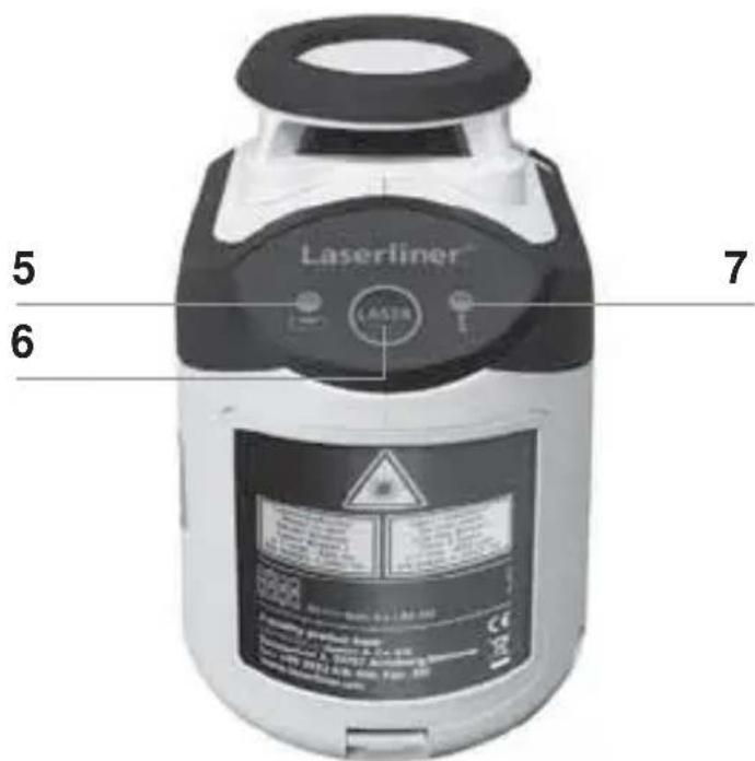
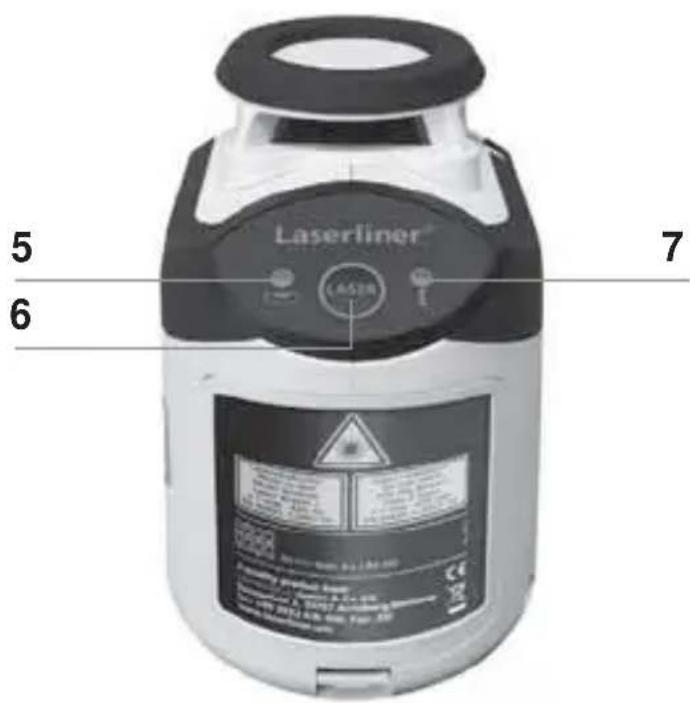
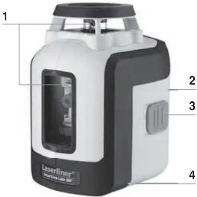
1 Laser output windows
4 5/8" tripod threads (bottom)
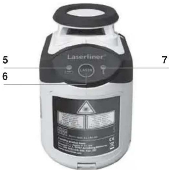
6 Laser line selection button; Hand receiver mode on/off
2 Battery compartment (backside)
5 LED levelling red: levelling off green: levelling on
7 LED hand receiver mode
3 ON/OFF switch; transport retainer
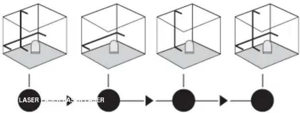
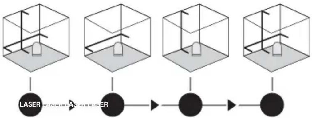
2 Horizontal and vertical levelling
Release the transport restraint, set the ON/OFF switch to „ ON“. The laser cross will appear. The laser lines can be switched individually with the selection button.
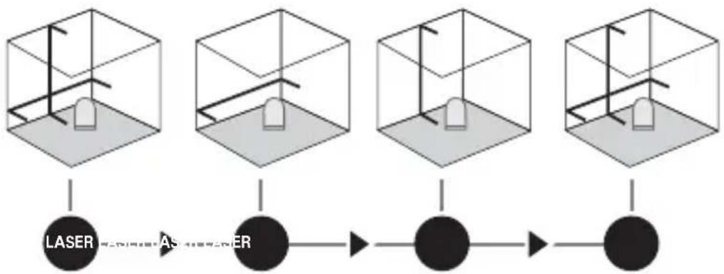

The transport restraint must be released for horizontal and vertical levelling. The laser lines flash and the LED lights red as soon as the device is outside the automatic levelling range of 5^ . Position the device such that it is within the levelling range. The LED switches back to green and the laser lines stop flashing (steady light).
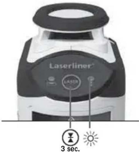
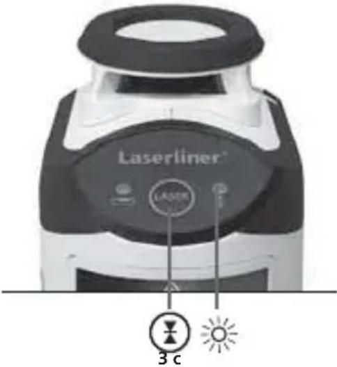
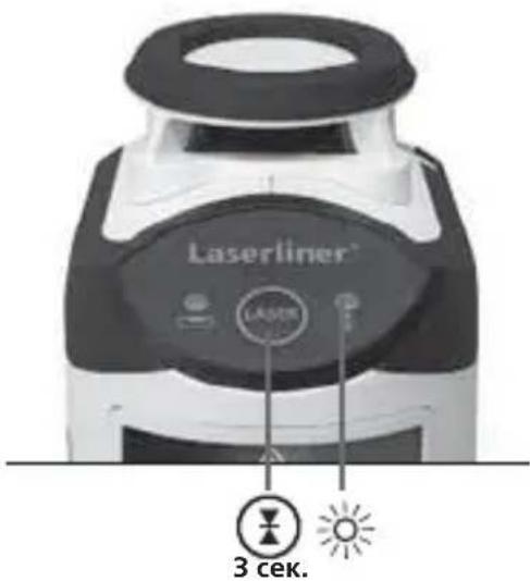
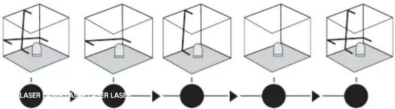
3 Hand receiver mode
Optional: Working with the laser receiver RX
Use an RX laser receiver (optional) to carry out levelling at great distances or when the laser lines are no longer visible. To work with a laser receiver, switch the line laser to hand-held receiver mode by keeping button 6 (hand-held receiver mode on / off) pressed. The laser lines will now pulsate with high frequency, making the laser lines darker. The laser receiver can detect these pulsating laser lines.

Observe the laser receiver's operating instructions for line lasers.

Due to the special optics required to generate a continuous 360^ laser line, the underlying technology may cause differences in brightness in different areas of the line. This may lead to different ranges in hand receiver mode.
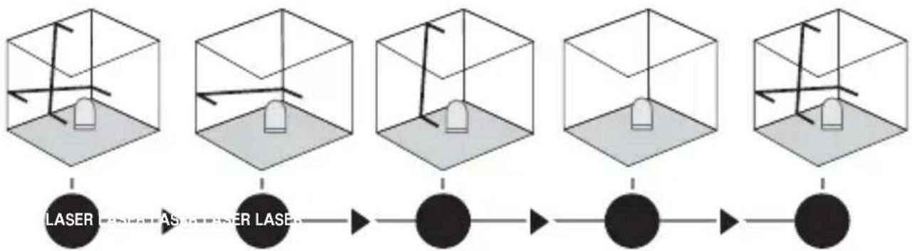
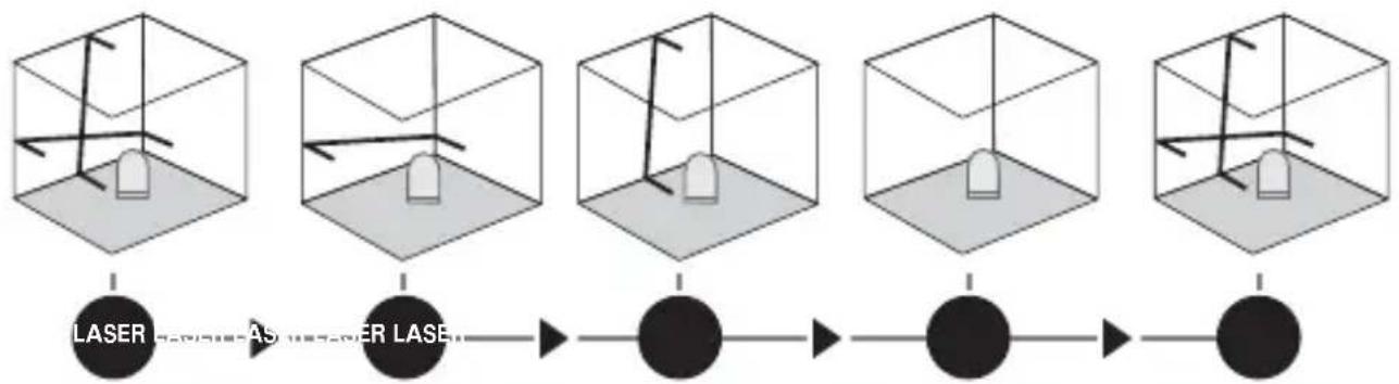
4 Slope mode
Do not release the transport restraint, set the ON/OFF switch to „ OFF". Select and switch on the laser with the selection button. Sloping planes can now be measured. This mode cannot be used to perform horizontal or vertical levelling as the laser lines are no longer aligned automatically. The LED lights constantly red.
Technical data
| Self-levelling range ± 5° | |
| Accuracy ± 0.4 mm / m | |
| Operating range (depending on room illumination) 20 m | |
| Working range with hand receiver (depends on how the technology affects the difference in brightness) | 10 - 30 m |
| Laser wavelength 635 nm | |
| Laser class / line laser output power 2 / < 1 mW | |
| Power supply | 4 x 1.5V alkaline batteries (type AA, LR6) |
| Operating time approx. 35 hours | |
| Operating temperature 0°C ... +40 °C | |
| Storage temperature -10°C ... +70 °C | |
| Dimensions (W x H x D) 75 x 130 x 100 mm | |
| Weight (incl. batteries) | 525 g |
Subject to technical changes without notice. 04.2013
Preparing the calibration check
It is possible for you to check the calibration of the laser. To do this, position the device midway between 2 walls, which must be at least 5 metres apart. Switch the device on (Laser cross ON). The best calibration results are achieved if the device is mounted on a tripod.
-
Mark point A1 on the wall.
-
Turn the device through 180^ and mark point A2. You now have a horizontal reference between points A1 and A2.
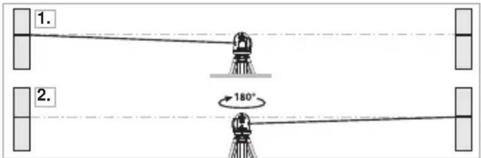
Performing the calibration check
- Position the device as near as possible to the wall at the height of point A1.
- Turn the device through 180^ and mark point A3. The difference between points A2 and A3 is the tolerance.
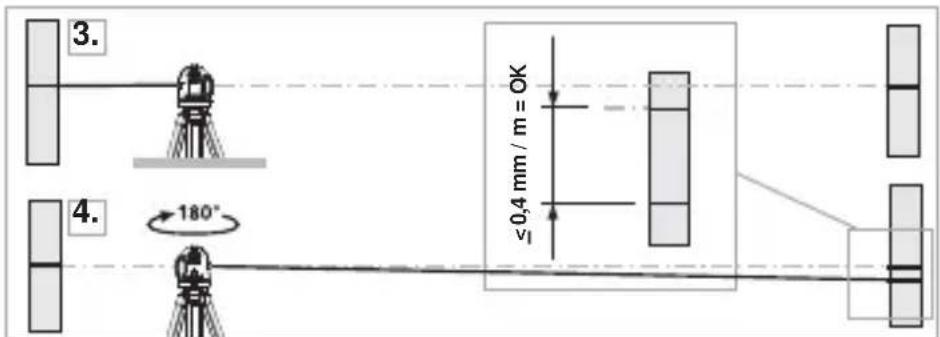

If points A2 and A3 are more than 0.4mm / m , the device is in need of calibration. Contact your authorised dealer or else the UMAREX-LASERLINER Service Department.
Checking the vertical line
Position the device about 5m from a wall. Fix a plumb bob with a line of 2.5m length on the wall, making sure that the bob can swing freely. Switch on the device and align the vertical laser to the plumb line. The precision is within the specified tolerance if the deviation between the laser line and the plumb line is not greater than ± 1.5mm .
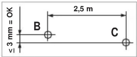
Checking the horizontal line
Position the device about 5m from a wall and switch on the cross laser. Mark point B on the wall. Turn the laser cross approx. 2.5m to the right and mark point C. Check whether the horizontal line from point C is level with point B to within ± 3mm . Repeat the process by turning the laser to the left.

Regularly check the calibration before use, after transport and after extended periods of storage.
Guarantee, product care and disposal
This device complies with all necessary standards for the free movement of goods within the EU.
This product is an electric device and must be collected separately for disposal according to the European Directive on waste electrical and electronic equipment.
Further safety and supplementary notices at:
www.laserliner.com/info

PoiroToBka K npOBepke KaII6pOBKn
BbI moKeTe npOBepnTb kaJIb6pOBky Ia3epa.ДЯ 3TOrO nOmeCTnte npi6op pOBHo nocepEnHe MeJdy 2 cTeHAM, pacCToHne MeJdy KOtOpbIMN DOJXHO 6bITb He MeHee 5 M. BkIIOHTe np6Op, ocBO6OuINB dJa 3TOrO fIKCaTOP dJa TpaHCnOPTnPOBKn (la3epHbI KpeCT BKIOUyeH).HaNJyUWe pe3yJIbTaTbI KaJIb6pOBKn MoxHO nOlyuHTb, ecJI np6Op yCTaHOBJeH Ha IStaTINB.
A B T O M A T N H N I P E X P E C H N I a3e p i 3 n epeI6aueH N M p e j K M O M p u H O R O p r i M a u d l a B u p i B H I O B a H N R I P L I T O K, C T i N O K, B i K O H, D V e p e T O S O.
3araIbHI Bka3iBKN no 6e3neci
Лаэрпевироминоваян!
He cnpraMOByBaTn noIJIa
Ha npomHb!
Ia3ep Knacy 2
<1 MBT·635 HM
EN 60825-1:2007-10
Ybara: He nBtbc npmo Ha na3epn npomnb! Na3ep He nobHHe nTpann B pyk ditei! He hnpabn T npnaad Ha IIOe 6e3 Heo6xidnocti. Ppnilad E kichm Bmipobalhnm la3epnmpnaIOM i Ha 100% HanaTobyCTbCn Ha 3aOdi Ha Bka3aHy ToHicTB. Lc stocyeTbCrapaHTII Ha npodyKT, XoYeMo Bka3aTH Ha Hactynhe: CiiD peryJnpho nepeBiprtn KaIbpyBaHHn Ppnilady nepei noro BVKOpncTahnM, nCJIa TpaHCnoptyBaHH Ta TpNbAloro 36epirAHN. Kpim toro, MIn Bka3yEmo Ha Te, 0o abcoIOTHe kaIbpyBaHH moXJIVe JnWe B cneiaIizOBaHm MaNCtepHi. BaWe kaIbpyBaHH MoKe 6yTu NnWe np6bn3Hm, i ToHicTb KaIbpyBaHH 3aJeKntb BiD CTapaHHocTi.
!
1 BctaHOBNTnakymyIaTOPN
BikpnBicikIg6atapeoK i BklaCTn 6atapeyn (4xTtn AA) 3rIO 3cIMBOJAMN.CiIKyBaTN 3a PJIAPHICTIO.


1 OTBipДЯВихODу Ia3epHOrO
4 5TAtnBHa pi3b6a 5/8" (HnxnCTopoHa)
6 KhonkaB6opy na3epnX liHi; YbIMKHeHH/ BmKHeHHpeKmMy pyHOrO npImMaaya
2 Bičík Дьla 6aTapešoK (3aДнЯ CTOpOHa)
5 CbitIOiOHe HIBeJIIOBaHHaHepBOHn: HIBeJIIOBaHHaBIMK. 3eJHn: HIBeJIIOBaHHaYBIMK.
7 CД-iHДиKaTOp peKIMy BnKOpNCTaHHa pyuHOrO npiMaHa
3 KHOIIKa BBIMKHeHHBIMKHeHH;BIOkyBaHH
2 TOpn3oHTaJIbHe i BepTnKaJIbHe HiBeJIIOBaHHa
Po3φikcyiTe TpaHcnpTHe cToNopiHHa, BCTaHOBITb BmNKaU yBIMKHeHHa/BmKHeHHa Ha «ON». 3'ЯВtbcra Na3epHe nepexpectra. KhoNkoU Bn6Opy MoXHa BMkKatu Na3epHi LiHii NooDInHci.

Дя gropиоюньно i Вертукально HIBeIOBahн Heo6xIDH O3ФICyBaTN TpaHCnOpTHe CTOnOpiHH. NocTiHNO CBITNbCz 3eJIeHn CBITNoIod.у pa3i BnxOdy 3a Mexi DiiaNa3OHy aBTOMaTHHO HIBeIOBahN, 70 cTaHOBtB 5°, La3epHi LiHII NOUHaOTb 6LIMaTn, a CBITNoIodHIn IHINKaTOp 3aRopAETbcry cepBOHm CBITlOM. Po3TaUyTe npINAad TaK, 706 BiH NOTpAnVB y Mexi DiiaNa3OHy aBTOMaTHHO HIBeIOBAHN. CBITNoI 3HOBy 3MiHNTb KOLip Ha 3eJIeHn, a La3epHi LiHII 3aRopAETbcr CTaIIM CBITlOM.
3 Pexim BnKopncTaNHpyHOro npiMaaya DoaTKOBO: ppaioe 3 Ja3epHm npiMaayem RX
Ipn BeNknx BiDcTaHx a6o KoJn Ia3epHi liHII
IOraHO BnDHO, CKOpNCtAaTeCra Ia3epHM npiMaueM
RX (He BXoDntb do cTaNdApTHoro KOMnJIeKTy).Uo6
IpaOBAtu 3 Ia3epHM npiMaueM, liHInHn
Ia3ep cIiD nepeMKHyTu B peKm pyHoro npiMaaya
TpNBaIIM HaTnCKaHHa KHONK 6 (yBIMKHeHH/
BIMKHeHHa pexmmy puHoro npiMaaya).Ipn
Zbomy Ia3epHi liHII nybcyBatmMyt b 3 6ilbwoIO
YactOTOIO, a RcKpaBicTB Ia3epHX liHIn 3MeHNITbcra.
3a DoNOMorOIO uix imnybcIB Ia3epHn npiMaay
po3Pi3Hae Ia3epHi liHII.

O6OB'3KOBO DoTpIMyIeCb nopAky ekCnnyatauII na3epHoro npiMaHa dIa IHHORo Ia3epa.

Yepe3 BnKOpNCTaHn CneuaJIbHOI ONTIKn IJRA NO6yIDOBn 6e3pepeBHOI Na3epHOI liHII Ha 360^ rckpaBicTB ocTaHHboI Ha pIHnx dIJIHKax MOxE pI3HNTsc, IIO o6ymoBJIeHO texHiuHmN npuHAmN. Lc MoXe PpIN3BOINTn Do KOJIINBaHb DaJIbHOCTi II B peXmI pyHOrO npInMaHa.
4 Pexim 3aBdaHnHaXnIy
He 3Himaoun 3 TpaHCnOpTHoro CtonopinH, BCTaHOBITb BmNKauch yBIMKHeHH/ BMKHeHHHa «OFF». YBIMKHITb Ia3epn KhoNkoIO Bn6Opy n o6epitb peKIM. Tepe moKHa 6yDyBaTN noxnlI pIoUHN. U cIbOMy peKMI He MOKHa 3dInChrTn rOpN3oHTaJIbHe a6o BePTnKaJIbHe HIBeJIIOBaHH, TOMy Ioo Ia3epHi IiHII BXe aBTOMaTHNo He BnpiBHIOTbcra. CBiTIOJIOHN iHINkATOp CBiTNTb chePBOHm CBiTLOM, He 6LIMAoun.
TexhiuHidahi
1 NoctabrayHa 6aTeepn
OTBOpTe THe3IOTO 3a 6atepnn n noctabete 6atepnnte (4xTnAA) cnopei nHCTaIauOnHHNTe CmBOJI. Pn TOBa CneJeTe 3a npaBnHa NOLpHOCT.

1 I3xoJen npo3opeu Ha Jana3epa
4 Pe36a Ha cTaTnBa 5/8" (OJHa cTpHa)
6 ByToH3a npeBkIIOUbaHe Ha Ia3epHn JInHn; BKn/IN3KHa peXnMa Ha pbueH npneMHNK
2 BaTePnIHo OTJeJIeHne (O6paTHa cTpaHa)
5 LED HnBeIipaHe cepBHeO: HnBeIipaHe n3KJI 3eJeHO: HnBeIpaHe BkJ
7 LED PeknM PbueH npneMHNK
3 IpeBkIIOUbaTeJI BKJ/IN3KJI; TpaHCnOpTHO o6e3oNaCBAHe
2 Xopn3oHTaJIHo n BepTnKaJIHo HnBeJnpaHe
Ocbo6oTe o6e3oNaC8BaHeTo npn TpaHcnpT, noCTaBeTe npeBknUoyBaTeJr AN/ AUS (BKJI/N3KJI) Ha "ON" (BKJI). NopBraBa ce na3epHnT Kpbct. Ype3 6yToHa 3a npBkIIOuBaHe MoKe Da Ce BKJIIOuBaT NOOTdEHNHO na3epHnTe JInHn.

3a xopn3oHTaJIHo n BepTnKaJIHo HnBeJInpaHe Tp86Ba Da ce ocBo6OJn TpaHcnpTo o6e3oJacraBaHe. LED cBETn noCToJHNO B 3eJeHO. LOM ypeIbT Ce HAMIPA N3BbN 30HaTa Ha aBTOMaTNUHO HnBeJInpaHe 5^ , JIa3epHnte JInHm MIRAT n LED cBETBa B cepBeHO. IOniNoHpaTe ypeDa TaKa, Ye da Ce HAMIPA BbTpE B 30HaTa Ha HnBeJInpaHe. LED OTHOBn PpeBKnIOUyBa Ha 3eJeHO n Ja3epHnte JInHm CBeTAY NOCToJHNO.
3 Pexim PbyeH PnemHK Po n36op: Pa60Tu c Ja3epHnA npneMHK RX
3a HnBeJIpaHe Ha roJeMn pa3cToHnI nn npi Beue HeBnIMn Ia3epHn IINHN n3IOJ3BaIte Ia3epeH npemHK RX (no n36op). 3a pa6ota c Ia3epHn npemHK BKIOUOte IINHeHHra Ia3ep 4pe3 dblro HATNCKaHe Ha 6yTOH 6 (peKm Ha pbueH npemHK Bk / n3Kn) B peKm Ha pbueH npemHK. Cera Ia3epHnTe IINHN nyLCnP aT C BnCoka YeCTOTA n Ia3epHnTe IINHN CTaBA T NO-TbMHn. Ia3epHnT npemHK pa3No3HaBA qpe3 TOBa nYlncpaHe Ia3epHnTe IINHN.

B3eMeTe npEiBnD PbKOBoIcTBOTO 3a eKcPiOaTaunHa Ja3epHnI npHeMnK 3a JInHeen Ja3ep.

Iopadn cneuaHata onTka 3a reHepipaHe Ha HnpeKbchata 360° Ia3epHa nnHna, MoKe Da ce nOBaT pa3NkB B npKOCTTa B pa3nnuHn 3OHN Ha nnHraTa, KOINTo Ca TexHnueckn oBycNoBeHn. ToBa moKe da IOBeDe Do pa3nnuHn paDnucn Ha DeiCTBne B peXm Ha pbYeH npneMHNK.
4 PekimHaKJIOH
He ocbo6oxdaBaIte oBe3OpacraBaHeto npTpaHcnpT, noCTaBeTe npeBknOuBaTeIe BkJI/N3KJI Ha "OFF" (N3KJI). BkIoute Te Ia3epnte c 6yToHa 3a npeBknIOUbaHe n 136epete. Cera Moxe da ce 3aIadat NaKIOHeH paBHHn. B To3n peXm He moKe Da Ce HnBeJInpa XOpN3OHTaJIHO, CbOTB. BePTNKaJIHO, Tb' KaTO Ja3epHnte JInHn Beue He ce HacOuBat aBTOMaTHNo. LED CBETn NOCToRHHo B cepBeHo.
TexHnueckxapaKTepeNCTnKN
- The automatic cross-line laser with integrated hand receiver mode for aligning tiles, wall studding, windows, doors etc.
- General safety instructions
- Inserting batteries
- Horizontal and vertical levelling
- Hand receiver mode
- Optional: Working with the laser receiver RX
- Slope mode
- Preparing the calibration check
- Performing the calibration check
- Checking the vertical line
- Checking the horizontal line
- Guarantee, product care and disposal
- PoiroToBka K npOBepke KaII6pOBKn
- A B T O M A T N H N I P E X P E C H N I a3e p i 3 n epeI6aueH N M p e j K M O M p u H O R O p r i M a u d l a B u p i B H I O B a H N R I P L I T O K, C T i N O K, B i K O H, D V e p e T O S O.
- 3araIbHI Bka3iBKN no 6e3neci
- BctaHOBNTnakymyIaTOPN
- TOpn3oHTaJIbHe i BepTnKaJIbHe HiBeJIIOBaHHa
- Pexim BnKopncTaNHpyHOro npiMaaya DoaTKOBO: ppaioe 3 Ja3epHm npiMaayem RX
- Pexim 3aBdaHnHaXnIy
- NoctabrayHa 6aTeepn
- Xopn3oHTaJIHo n BepTnKaJIHo HnBeJnpaHe
- Pexim PbyeH PnemHK Po n36op: Pa60Tu c Ja3epHnA npneMHK RX
- PekimHaKJIOH
Brand : Laserliner
Model : SmartLine Laser 360
Category : Laser pointer