
EW2051H - Water pump MAKITA - Free user manual and instructions
Find the device manual for free EW2051H MAKITA in PDF.
| Product type | Self-priming water pump for semi-loaded water |
| Brand | Makita |
| Model | EW2051H |
| Suction diameter × discharge | 50 × 50 mm |
| Total head | 32 m |
| Max discharge flow rate | 700 L/min |
| Suction height | 8.0 m |
| Engine type | Air-cooled 4-stroke gasoline engine with overhead camshaft |
| Engine model | EX16 |
| Fuel | Unleaded automotive gasoline (max 10% ethanol or 15% MTBE) |
| Fuel tank volume | 3.2 L |
| Engine oil tank volume | 0.6 L |
| Engine oil type | Detergent 4-stroke oil API SE or higher (SG, SH, SJ), viscosity according to temperature |
| Spark plug | TORCH E6RC or NGK BR-6HS |
| Starting system | Recoil starter |
| Dimensions (L × W × H) | 527 × 368 × 417 mm |
| Net weight | 24.9 kg |
| Mechanical seal material | Silicon carbide |
| Sound pressure level | 87 dB(A) |
| Guaranteed sound power level | 103 dB(A) |
| Included accessories | Engine tools, strainer, hose fittings (2 sets), hose clamps (3), hex wrench, instruction manual |
Frequently Asked Questions - EW2051H MAKITA
User questions about EW2051H MAKITA
0 question about this device. Answer the ones you know or ask your own.
Ask a new question about this device
Download the instructions for your Water pump in PDF format for free! Find your manual EW2051H - MAKITA and take your electronic device back in hand. On this page are published all the documents necessary for the use of your device. EW2051H by MAKITA.
USER MANUAL EW2051H MAKITA
natural_image
Technical line drawing of a mechanical pump or generator unit (no text or symbols visible)1
2
①

natural_image
Technical line drawing of a mechanical pump assembly with hoses and fittings (no text or symbols)②
natural_image
Technical line drawing of a mechanical pump assembly with hoses and tubing (no text or symbols)③
bar
| Grade | Temperature Range (°C) | |---|---| | Single grade | -20 to 0 | | Single grade | -4 to 0 | | Single grade | 0 to 30 | | Single grade | 30 to 68 | | Single grade | 68 to 86 | | Single grade | 86 to 104 | | Single grade | 104 to 120 | | Single grade | 120 to 140 | | Single grade | 140 to 160 | | Single grade | 160 to 180 | | Single grade | 180 to 200 | | Single grade | 200 to 220 | | Single grade | 220 to 240 | | Single grade | 240 to 260 | | Single grade | 260 to 280 | | Single grade | 280 to 300 | | Single grade | 300 to 320 | | Single grade | 320 to 340 | | Single grade | 340 to 360 | | Single grade | 360 to 380 | | Single grade | 380 to 400 | | Multi grade | -20 to 0 | | Multi grade | -4 to 0 | | Multi grade | 0 to 30 | | Multi grade | 30 to 68 | | Multi grade | 68 to 86 | | Multi grade | 86 to 104 | | Multi grade | 104 to 120 | | Multi grade | 120 to 140 | | Multi grade | 140 to 160 | | Multi grade | 160 to 180 | | Multi grade | 180 to 200 | | Multi grade | 200 to 220 | | Multi grade | 220 to 240 | | Multi grade | 240 to 260 | | Multi grade | 260 to 280 | | Multi grade | 280 to 300 | | Multi grade | 300 to 320 | | Multi grade | 320 to 340 | | Multi grade | 340 to 360 | | Multi grade | 360 to 380 | | Multi grade | 380 to 400 | Ambient temperature: -20 to -4 Ambient temperature: -4 to -14 Ambient temperature: -14 to -32 Ambient temperature: -32 to -50 Ambient temperature: -50 to -68 Ambient temperature: -68 to -86 Ambient temperature: -86 to -104 Ambient temperature: -104 to -120 Ambient temperature: -120 to -140 Ambient temperature: -140 to -160 Ambient temperature: -160 to -180 Ambient temperature: -180 to -200 Ambient temperature: -200 to -220 Ambient temperature: -220 to -240 Ambient temperature: -240 to -260 Ambient temperature: -260 to -280 Ambient temperature: -280 to -300 Ambient temperature: -300 to -320 Ambient temperature: -320 to -340 Ambient temperature: -340 to -360 Ambient temperature: -360 to -380 Ambient temperature: -380 to -400 Ambient temperature: -400 to -420 Ambient temperature: -420 to -440 Ambient temperature: -440 to -460 Ambient temperature: -460 to -480 Ambient temperature: -480 to -500 Ambient temperature: -500 to -520 Ambient temperature: -520 to -540 Ambient temperature: -540 to -560 Ambient temperature: -560 to -580 Ambient temperature: -580 to -600 Ambient temperature: -600 to -620 Ambient temperature: -620 to -640 Ambient temperature: -640 to -660 Ambient temperature: -660 to -680 Ambient temperature: -680 to -700 Ambient temperature: -700 to -720 Ambient temperature: -720 to -740 Ambient temperature: -740 to -760 Ambient temperature: -760 to -780 Ambient temperature: -780 to -800 Ambient temperature: -800 to -820 Ambient temperature: -820 to -840 Ambient temperature: -840 to -860 Ambient temperature: -860 to -880 Ambient temperature: -880 to -900 Ambient temperature: -900 to -920 Ambient temperature: -920 to -940 Ambient temperature: -940 to -960 Ambient temperature: -960 to -980 Ambient temperature: -980 to -100 Ambient temperature: -1.1 (F) or above④
⑤
⑥
natural_image
Illustration of two workers operating a portable industrial machine (no text or symbols visible)⑦
natural_image
Mechanical assembly diagram showing a lever lifting a component (no text or symbols visible)3
①
②
③
natural_image
Line drawing of a car interior showing hand positioning and gear shift (no text or symbols)④
5
natural_image
Illustration of a hand using a tool to adjust or install a mechanical component (no text or symbols visible)⑥
natural_image
Line drawing of a car interior showing hand positioning and valve mechanism (no text or symbols)4
①
②

5
①
②
③
④
natural_image
Illustration of a hand turning a mechanical component with a circular housing (no text or symbols)6

7
①
②

natural_image
Technical line drawing of a mechanical assembly with no visible text or symbols③
natural_image
Line drawing of a hand operating a mechanical device with no visible text or symbols④
5
6
natural_image
Line drawing of a hand using a tool to adjust or install a mechanical component (no text or symbols visible)8
natural_image
Mechanical assembly diagram showing fluid flow from a pump into a tank (no text or symbols)⑦
natural_image
Technical line drawing of a mechanical assembly with a magnified inset showing a tool (no text or symbols present)②
natural_image
Technical illustration of a mechanical assembly with a motor and baseplate (no text or symbols)⑧
natural_image
Technical line drawing of a mechanical assembly with no visible text or symbols③
natural_image
Illustration of two workers operating a portable water heater, one holding a tool and gesturing, the other gesturing with open hands (no text or symbols present)⑨
10
natural_image
Technical line drawing of a mechanical assembly with no visible text or symbolsEnglish (Original instructions)
FOREWORD
Thank you very much for purchasing a MAKITA PUMP.
This manual covers operation and maintenance of MAKITA PUMP.
All information in this publication is based on the latest product information available at the time of approval for printing. Please read this manual carefully before operating.
Please take a moment to familiarize yourself with the proper operation and maintenance procedures in order to maximize the safe and efficient use of this product.
Keep this owner's manual at hand, so that you can refer to it at any time.
Due to constant efforts to improve our products, certain procedures and specifications are subjected to change without notice.
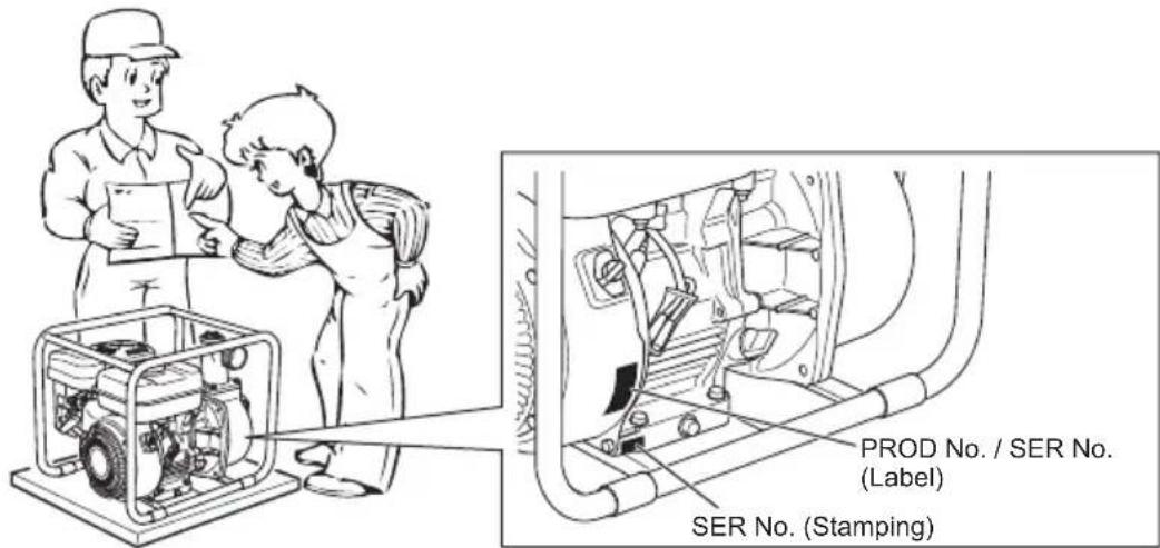
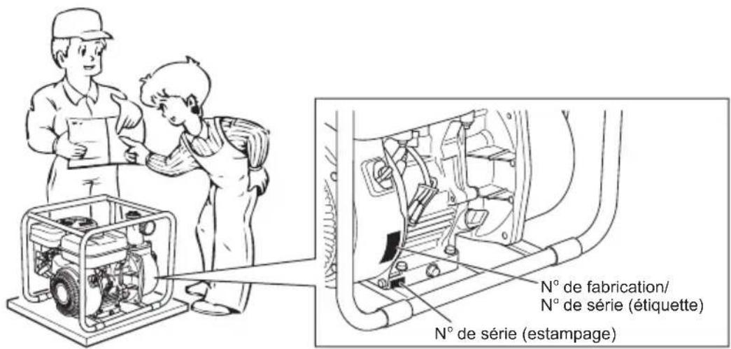
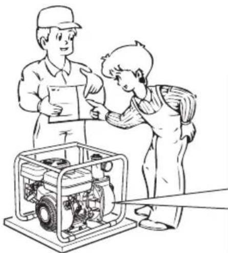
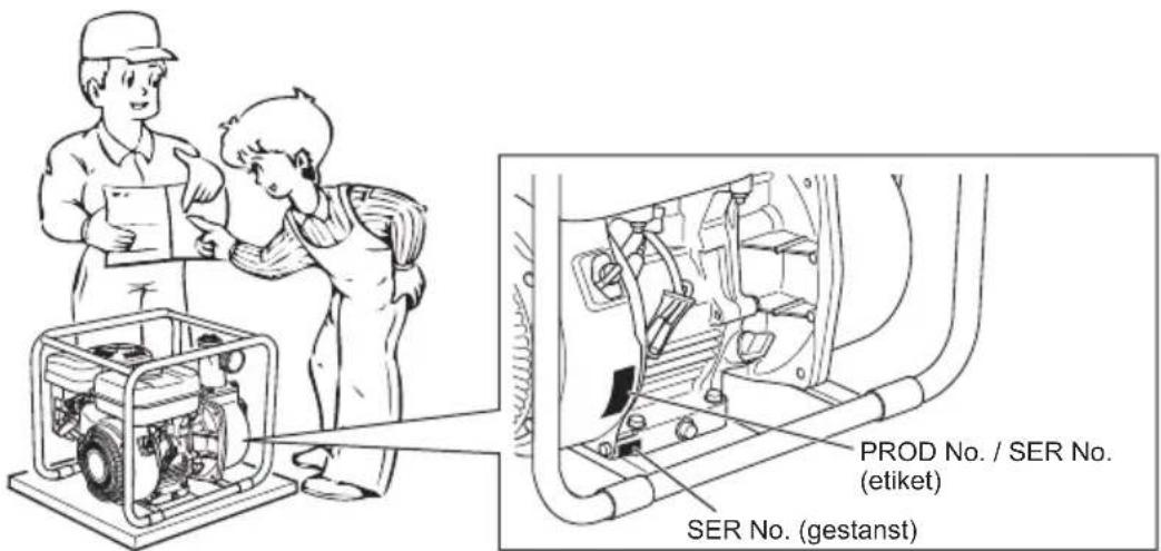
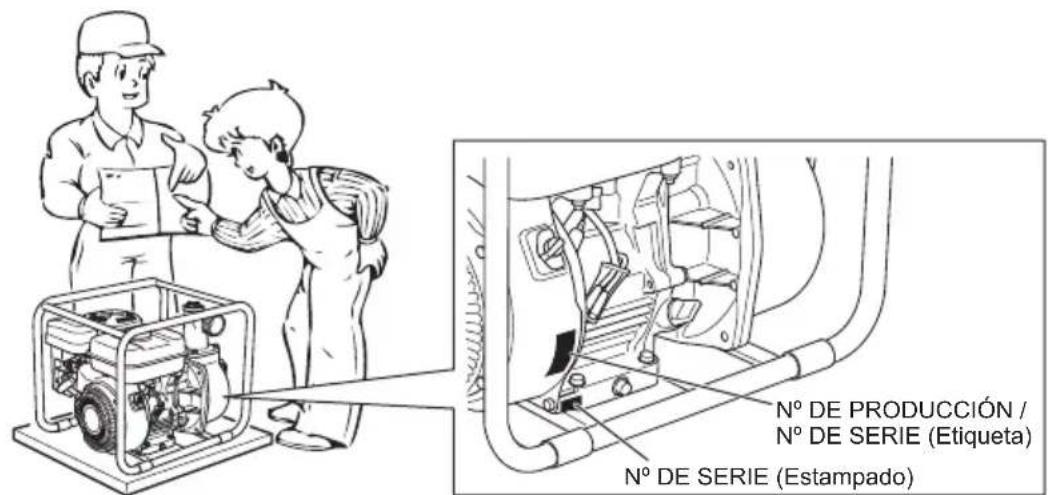
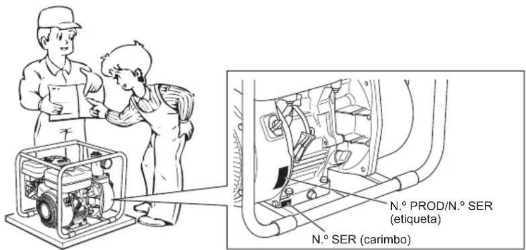
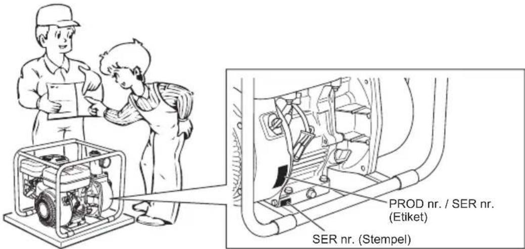
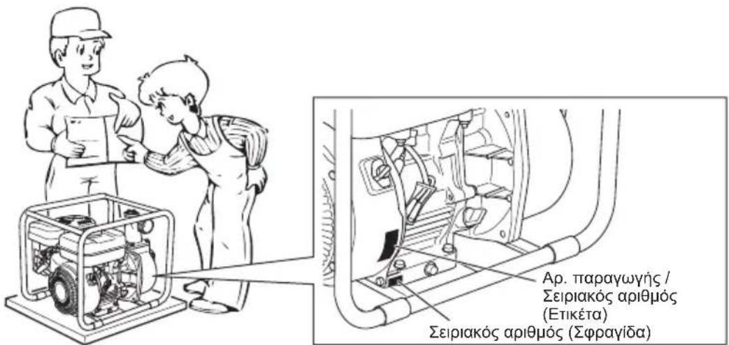
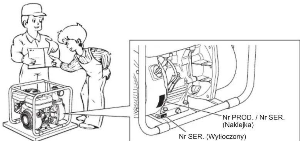
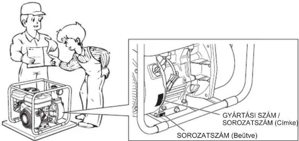
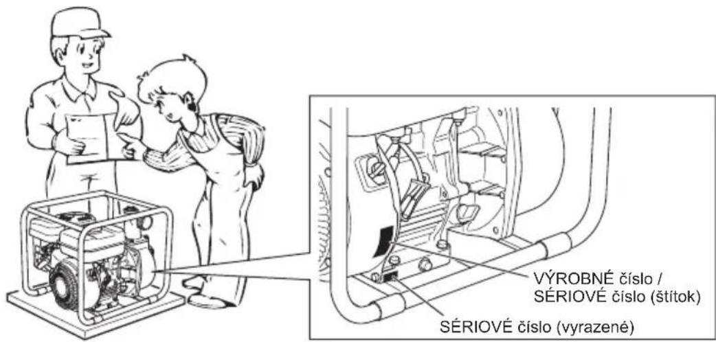
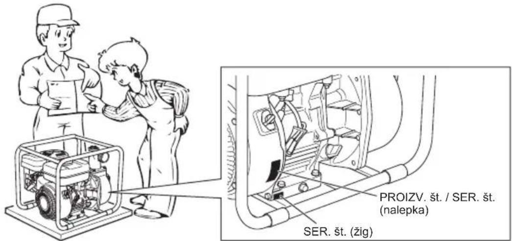
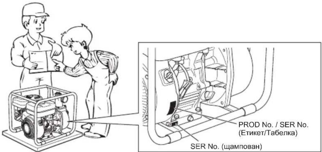
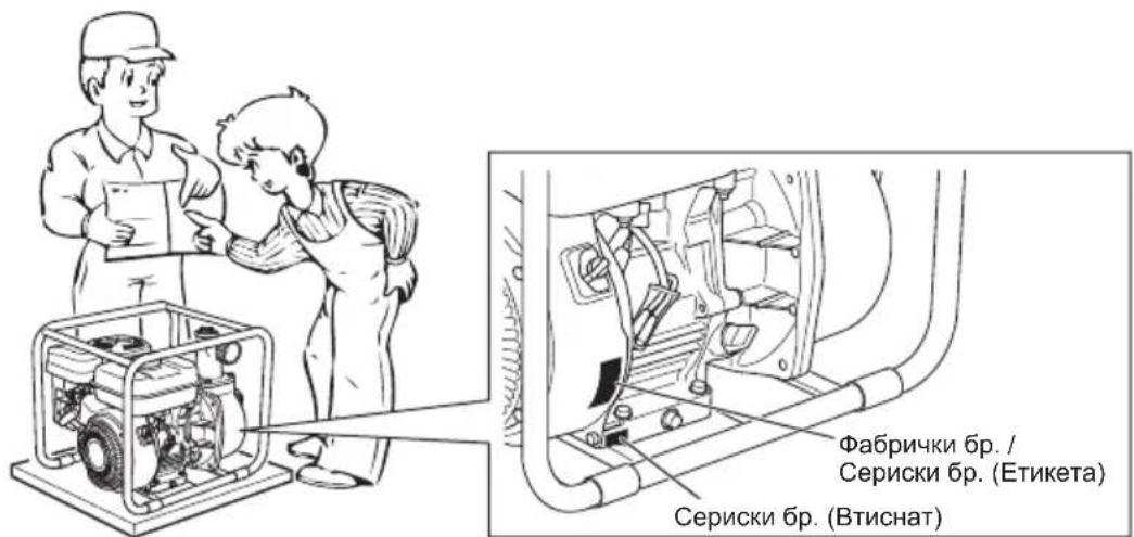
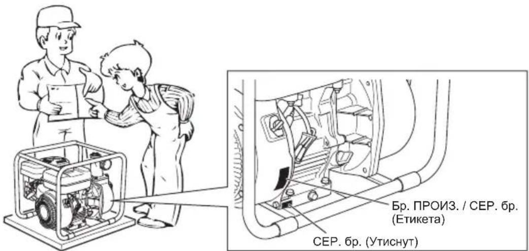
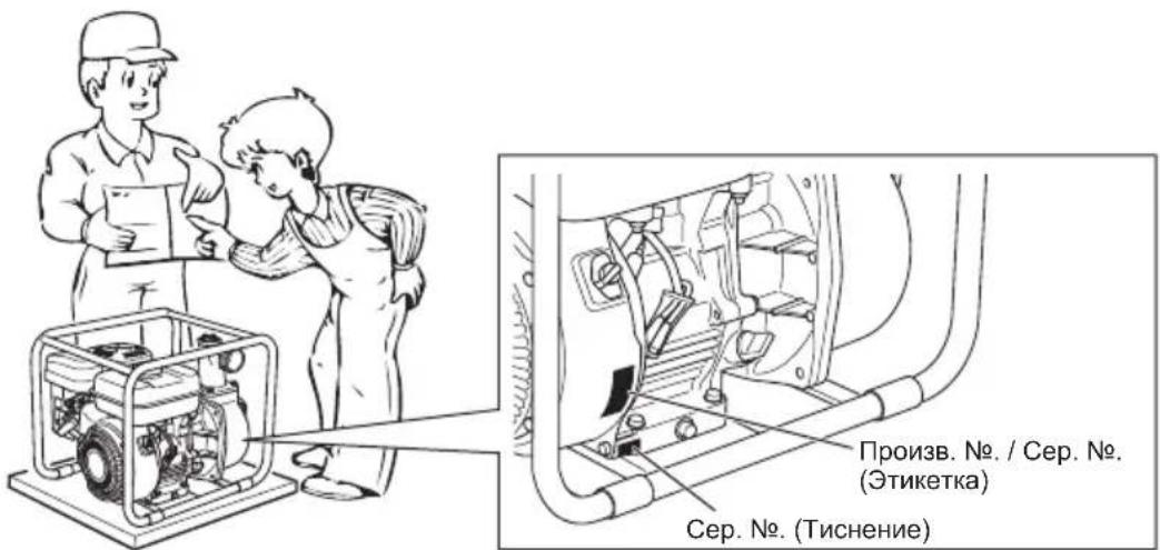
When ordering spare parts, always give us the MODEL, PRODUCTION NUMBER and SERIAL NUMBER of your pump.
Please fill in the following blanks after checking the production number on your pump. (Location of label is different depending on the product specification.)

CONTENTS
Page
-
SAFETY PRECAUTIONS 2
-
COMPONENTS....4
-
PRE-OPERATION FOR STARTING 5
-
OPERATING YOUR PUMP....6
-
MAINTENANCE 6
-
PREPARATIONS FOR STORAGE 9
-
OIL SENSOR INSTRUCTIONS....9
-
EASY TROUBLESHOOTING 10
-
SPECIFICATIONS....11
-
EC DECLARATION OF CONFORMITY ..... 11
NOTE
Please refer to the illustrations on the back page of the front cover for Fig. 1 to indicated in the sentence.
1. SAFETY PRECAUTIONS
Please make sure you review each precaution carefully.
Pay special attention to statement preceded by the following words.
WARNING
"WARNING" indicates a strong possibility of severe personal injury or loss of life if instructions are not followed.
CAUTION
"CAUTION" indicates a possibility of personal injury or equipment damage if instructions are not followed.
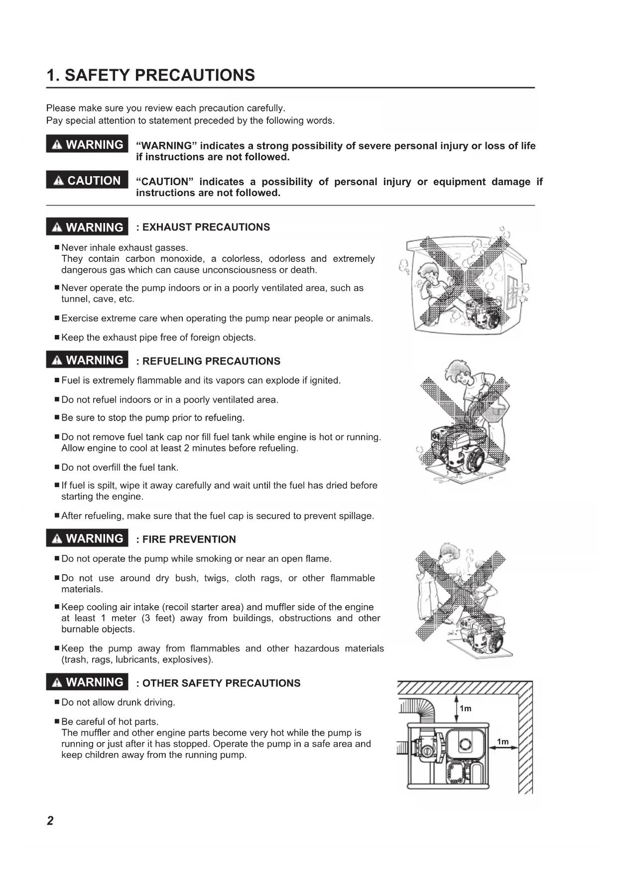
WARNING : EXHAUST PRECAUTIONS
■ Never inhale exhaust gasses.
They contain carbon monoxide, a colorless, odorless and extremely dangerous gas which can cause unconsciousness or death.
■ Never operate the pump indoors or in a poorly ventilated area, such as tunnel, cave, etc.
■ Exercise extreme care when operating the pump near people or animals.
- Keep the exhaust pipe free of foreign objects.
WARNING : REFUELING PRECAUTIONS
■ Fuel is extremely flammable and its vapors can explode if ignited.
■ Do not refuel indoors or in a poorly ventilated area.
■ Be sure to stop the pump prior to refueling.
■ Do not remove fuel tank cap nor fill fuel tank while engine is hot or running. Allow engine to cool at least 2 minutes before refueling.
■ Do not overfill the fuel tank.
■ If fuel is spilt, wipe it away carefully and wait until the fuel has dried before starting the engine.
■ After refueling, make sure that the fuel cap is secured to prevent spillage.
WARNING : FIRE PREVENTION
■ Do not operate the pump while smoking or near an open flame.
■ Do not use around dry bush, twigs, cloth rags, or other flammable materials.
- Keep cooling air intake (recoil starter area) and muffler side of the engine at least 1 meter (3 feet) away from buildings, obstructions and other burnable objects.
- Keep the pump away from flammables and other hazardous materials (trash, rags, lubricants, explosives).
WARNING : OTHER SAFETY PRECAUTIONS
■ Do not allow drunk driving.
■ Be careful of hot parts.
The muffler and other engine parts become very hot while the pump is running or just after it has stopped. Operate the pump in a safe area and keep children away from the running pump.

natural_image
Illustration of a child inside a building with smoke and dust clouds (no text or symbols)
natural_image
Illustration of a person operating a small wheeled robot with wheels, surrounded by geometric patterns (no text or symbols)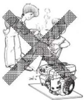
natural_image
Illustration of a person washing clothes next to a machine (no text or symbols visible)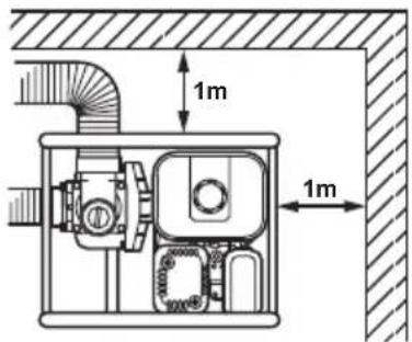
■ Do not touch the ignition cable when starting and operating the engine.
■ Operate the pump on a stable, level surface. If the engine is tilted, fuel spillage may result.
NOTE
Operating the pump at a steep incline may cause seizure due to improper lubrication even with a maximum oil level.
■ Do not transport the pump with fuel in tank or with fuel strainer valve open.
- Keep the unit dry (do not operate it in rainy conditions).

WARNING : PRE-OPERATION CHECKS
■ Carefully check fuel hoses and joints for looseness and fuel leakage. Leaked fuel creates a potentially dangerous situation.
■ Check bolts and nuts for looseness. A loose bolt or nut may cause serious engine trouble.
■ Check the engine oil and refill if necessary.
■ Check the fuel level and refill if necessary. Take care not to overfill the tank.
- Keep cylinder fins and recoil starter free of dirt, grass and other debris.
■ Wear snug fitting working clothes when operating the engine.
Loose aprons, towels, belt, etc., may be caught in the engine or drive train, causing a dangerous situation.

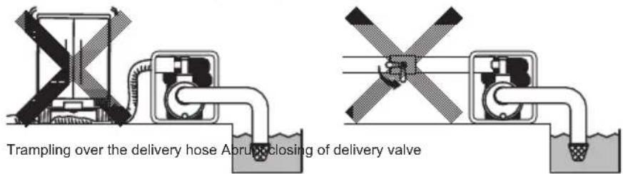
CAUTION : BEWARE OF WATER-HAMMERING
- Do not allow the delivery hose to be trampled over by a vehicle's wheel, or do not close the delivery valve abruptly otherwise a water-hammer occurs which may result heavy damage to the pump.
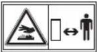
SYMBOLS
 | Read manual. |  | Shut off fuel valve when the engine is not in use. |
 | Stay clear of the hot surface. |  | Check for leakage from hose and fittings. |
 | Exhaust gas is poisonous.Do not operate in an unventilated room or enclosed area. |  | Fire, open flame and smoking prohibited. |
 | Stop the engine before refueling. |  | HOT, avoid touching the hot area. |
| On (Run) | Engine start(Electric start) | Fuel (gasoline) Primer | |||||
 ) Engine stop ) Engine stop |  | Fuel (diesel) Push primer | |||||
 il Cold engine Fuel shut-off il Cold engine Fuel shut-off | [008X] | Do not push primer | |||||
 Add oil Warm engine Add oil Warm engine |  | Fuel systemfailure / malfunction | 2X | Two times | |||
 | Electrical preheat(Low temperature start aid) | [264H] | Choke | ||||
| [KKSY] position |  | Plus ;positive polarity | |||||
 position position |  | Minus ;negative polarity | |||||
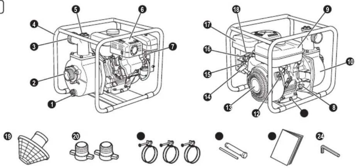
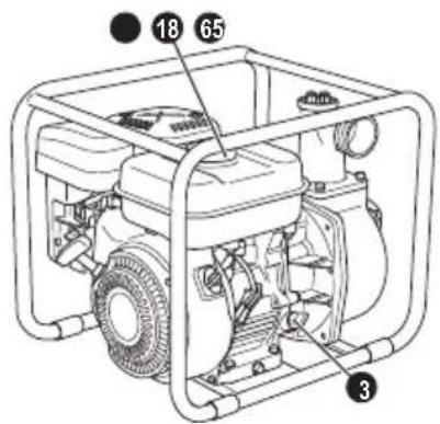
2. COMPONENTS
(See Fig.)
NOTE
Please refer to the illustrations on the back page of the front cover or back cover for Fig. 1 to 8 indicated in the sentence.
1 Plug (drain)
② Suction
3 Delivery
4 Frame
⑤ Plug (priming)
6 Muffler
⑦ Spark plug
8 Oil filler (with oil guage)
9 Fuel tank
10 Casing cover
Drain plug (at two places)
12 Stop Switch
13 Recoil starter
14 Recoil Starter handle
15 Fuel valve
16 Chocke lever
17 Air cleaner
18 Speed control lever
19 Strainer
20 Hose coupling
21 Hose band
22 Tools
23 Instruction for use (This publication)
24 Hexagon wrench (Semi trash pump only)
3. PRE-OPERATION FOR STARTING
(See Fig. 2)
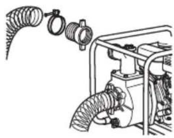
1. CONNECT SUCTION HOSE (See Fig. 2)①
Use a reinforced-wall or wire braided hose to prevent suction collapse. Since the pump self-priming time is directly proportional to hose length, a short hose is recommended.
CAUTION
Always use a strainer with the suction hose. Gravel or debris sucked into the pump will cause serious damage to the impeller and the pump casing.
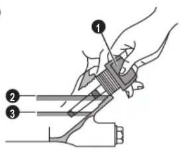
2. CONNECT DELIVERY HOSE (See Fig.2-2)
When using a fabric hose, always use a hose band to prevent the hose from disconnecting under high pressure.
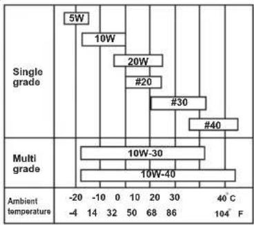
3. CHECK ENGINE OIL (See Fig. 2)④
Before checking or refilling engine oil, be sure the engine is located on stable, level surface and stopped.
■ Do not screw the oil gauge into the oil filler neck to check oil level. If the oil level is low, refill to the upper level with the following recommended oil.
■ Use 4-stroke automotive detergent oil of API service class SE or higher grade (SG, SH or SJ is recommended).
■ Select the viscosity based on the air temperature at the time of operation as shown in the table.
(See Fig. 2-3)
Explanation of Fig. 2④
① Oil Gauge Upper Level
3 Lower Level
| Model Oil capacity | |
| EW2050H | 0.6 L |
| EW3050H | |
| EW2051H | |
| EW3051H | |
4. CHECK FUEL (See Fig. 2-5)
WARNING
■ Do not refuel while smoking, near an open flame or other such potential fire hazards. Otherwise fire accident may occur.
■ Remove the statistic electricity from your body before refilling the gasoline. Sparking from electrostatic discharge may cause the ignition to the vaporized fuel (gasoline) resulting burns.
Static electricity can be discharged from the body by touching by hand the metal parts of the unit and the fuel dispensing pump.
NOTE THIS ENGINE IS CERTIFIED TO OPERATE ON AUTOMOTIVE UNLEADED GASOLINE.
■ Stop the engine and open the cap.
■ Use automotive unleaded gasoline only.
- Unleaded regular/premium or reformulated gasoline containing no more than 10% Ethanol (E10), or 15% MTBE may also be used.
- Never use gasoline containing ethanol exceeding 10%, or MTBE exceeding 15% because engine or fuel system damage could result.
- Never use stale or contaminated gasoline.
- Use of these non-recommended fuels may result in reduced performance and/or denial of warranty.
Fuel Tank Capacity
| Model | Fuel Tank capacityLitre (U.S.gal) |
| EW2050H | 3.2 (0.85) |
| EW3050H | |
| EW2051H | |
| EW3051H |
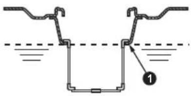
■ Close the fuel valve before filling the fuel tank.
- Do not fill above the top of the fuel filter screen (marked 1), or the fuel may overflow when it heats up later and expands.
Explanation of Fig. 2 ⑤
① Maximum Fuel level
■ When filling the fuel tank, always use the fuel filter screen.
■ Reattach the fuel cap by turning clockwise until reaching the physical stop (about one quarter turn). Do not attempt to turn past the physical stop or the fuel cap may be damaged.
■ Wipe off any spilled fuel before starting the engine. (See Fig. 2-6)
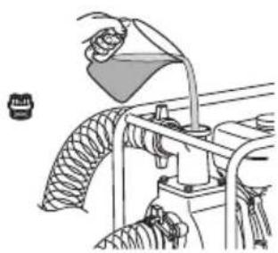
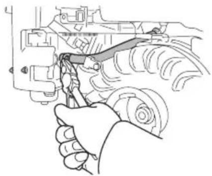
5. CHECK PRIMING WATER (See Fig. 2)⑦
It is recommended that the water chamber of pump casing should be primed with full of water before operating.
WARNING
Never attempt to operate the pump without priming water or the pump will overheat. Extended dry operation will destroy the mechanical seal.
If the unit has been operated dry, stop the engine immediately and allow the pump to cool before adding priming water.
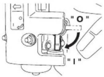
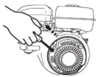
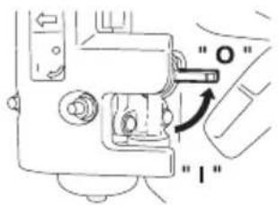
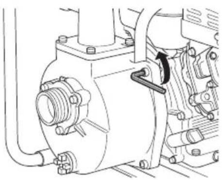
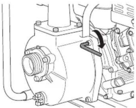
(1) Open the fuel valve. (See Fig. 3)①
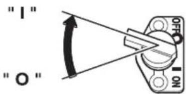
(2) Turn the STOP SWITCH to the position "I" (ON). (See Fig. 3-2)
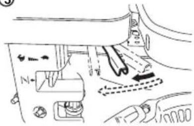
(3) Set the speed control lever 1/3 of the way towards the high speed position. (See Fig. 3-3)
(4) Close the choke lever. (See Fig. 3-4)
■ If the engine is cold or the ambient temperature is low, close the choke lever fully.
■ If the engine is warm or the ambient temperature is high, open the choke lever half-way, or keep it fully open.
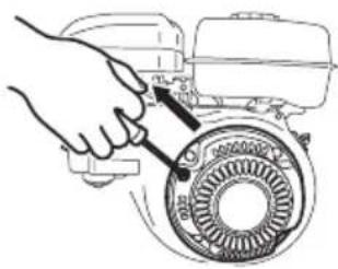
(5) Pull the starter handle slowly until resistance is felt. This is the "compression" point. Return the handle to its original position and pull swiftly. Do not pull out the rope all the way. After starting the engine, allow the starter handle to return to its original position while still holding the handle. (See Fig.3-5)
(6) After starting the engine, gradually open choke by turning the choke lever and finally keep it fully opened. Do not fully open the choke lever immediately when the engine is cold or the ambient temperature is low, because the engine may stop. (See Fig. 3-6)
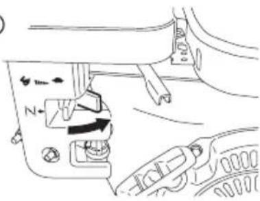
2. RUNNING (See Fig. 4)
(1) After the engine starts, set the speed control lever at the low speed position (L) and warm it up without load for a few minutes. (See Fig. 4-①)
(2) Gradually move the speed control lever toward the high speed position (H) and set it at the required engine speed. (See Fig. 4-2)
■ Whenever high speed operation is not required, slow the engine down (idle) by moving the speed control lever to save fuel and extend engine life.
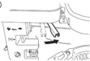
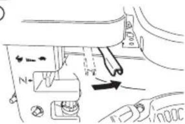
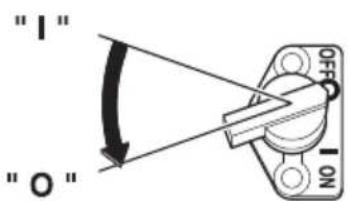
3. STOPPING (See Fig. 5)
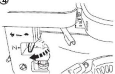
(1) Set the speed control lever at the low speed position and allow the engine to run at low speed for 1 or 2 minutes before stopping. (See Fig. 5-1)
(2) Turn the STOP SWITCH counterclockwise to the position "O" (OFF). (See Fig. 5)②
(3) Close the fuel valve. (See Fig. 5-3)
(4) Pull the starter handle slowly and return the handle to its original position when resistance is felt. This operation is necessary to prevent outside moist air from intruding into the combustion chamber.
(See Fig. 5-4)
※ STOPPING ENGINE WITH THE FUEL VALVE
Close the fuel valve and wait for a while until the engine stops. Avoid to let the fuel remain in the carburetor over long periods, or the passages of the carburetor may become clogged with impurities, and malfunctions may result.
5. MAINTENANCE
(See Fig. 8)
1. DAILY INSPECTION
Before running the engine, check the following service items.
① Loose or broken bolts and nuts
② Clean air cleaner element
③ Enough clean engine oil
④ Leakage of gasoline and engine oil
⑤ Enough gasoline
6 Safe surroundings
⑦ Check the priming water
8 Excessive vibration, noise
2. PERIODIC INSPECTION
Periodic maintenance is vital to the safe and efficient operation of your pump.
Check the table below for periodic maintenance intervals.
The below chart is based on the normal product operation schedule.
CAUTION
Replace rubber pipes for fuel passage every two years. If fuel leakage is found, replace the pipe immediately.
Periodic Maintenance Schedule table
| Maintenance Items Every 8 hours | (Daily) | Every 50 hours (Weekly) | Every 200 hours (Monthly) | Every 300 hours | Every 500 hours | Every 1000 hours |
| CLEAN PUMP SET AND CHECK BOLTS AND NUTS | ● (Daily) | |||||
| CHECK FOR LEAKAGE FROM HOSES AND FITTING | ● (Daily) | |||||
| CHECK AND REFILL ENGINE OIL | ● (Refill daily up to upper level) | |||||
| CHANGE ENGINE OIL | ● (Initial 20 hours) | ● (Every 100 hours) | ||||
| CLEAN SPARK PLUG | ● (Every 100 hours) | |||||
| CLEAN AIR CLEANER | ● | |||||
| REMOVE THE PUMP CASING AND CLEAN | ● | |||||
| CLEAN FUEL STRAINER | ● | |||||
| CLEAN AND ADJUST SPARK PLUG AND ELECTRODES | ● | |||||
| CHECK AND ADJUST VALVE CLEARANCE | ● | |||||
| REMOVE CARBON FROM CYLINDER HEAD | ● | |||||
| CLEAN AND ADJUST CARBURETOR | ● | |||||
| REPLACE FUEL HOSE | ● (Every 2 years) | |||||
| OVERHAUL ENGINE IF NECESSARY | ● | |||||
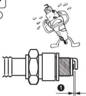
3. INSPECTING THE SPARK PLUG
(See Fig. 7)①
(1) Clean off carbon deposits on the spark plug electrode using a plug cleaner or wire brush.
(2) Check electrode gap. The gap should be 0.6 mm to 0.7 mm (0.02 inch.-0.03 inch.). Adjust the gap, if necessary, by carefully bending the side electrode.
Recommended Spark Plug: E6RC (TORCH) or BR-6HS (NGK)
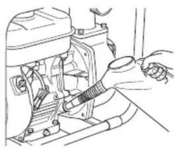
4. ENGINE OIL CHANGE (See Fig. 7, 2) ③
Initial oil change : After 20 hours of operation Thereafter : Every 100 hours of operation
(1) When changing oil, stop the engine and loosen the drain plug. Drain the used oil while the engine is warm. Warm oil drains quickly and completely.
CAUTION
To prevent injury, pay attention to the hot oil. Make sure the fuel cap is tightly secured to avoid spillage.
(2) Re-install the drain plug before refilling oil.
| Model Oil capacity | |
| EW2050H | 0.6 L |
| EW3050H | |
| EW2051H | |
| EW3051H | |
(3) Refer to page 5 for the recommended oil.
■ Always use the best grade and clean oil. Contaminated oil, poor quality oil and shortage of oil cause damage to engine or shorten the engine life.
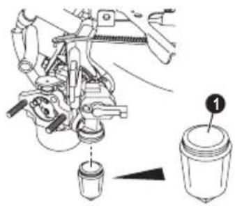
5. CLEANING FUEL CUP (See Fig. 7)④

WARNING
Flame Prohibited
WARNING
Remove the statistic electricity from your body before refilling the gasoline.
Sparking from electrostatic discharge may cause the ignition to the vaporized fuel (gasoline) resulting burns.
Static electricity can be discharged from the body by touching by hand the metal parts of the unit.
(1) Inspect fuel cup for water and dirt. (See Fig. 7-4)①
(2) To remove water and dirt, close the fuel valve and remove the fuel cup.
(3) After removing dirt and water, wash the fuel cup with kerosene or gasoline. Reinstall securely to prevent leakage.
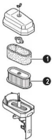
6. CLEANING AIR CLEANER (See Fig. 7)⑤
A dirty air cleaner element will cause starting difficulty, power loss, engine malfunctions, and shorten engine life extremely.
Always keep the air cleaner element clean.
WARNING
Flame Prohibited
■ Urethane Foam cleaning (See Fig. 7-5) 2 Wash and clean the urethane foam with detergent. After cleaning, dry it. Clean the urethane foam element every 50 hours.
■ Second element (See Fig. 7-5) Clean by tapping gently to remove dirt and blow off dust. Never use oil. Clean the paper element every 50 hours of operation, and replace element set every 200 hours.
NOTE
Clean and replace air cleaner elements more often when operating in dusty environments. Replace the element in case that dirt or dust can not be removed and/or that the element is deformed or deteriorated.
7. FUEL HOSE REPLACEMENT (See Fig. 7)⑥
WARNING
■ Take extreme caution when replacing fuel hose; gasoline is extremely flammable.
■ Remove the statistic electricity from your body before refilling the gasoline.
Sparking from electrostatic discharge may cause the ignition to the vaporized fuel (gasoline) resulting burns.
Static electricity can be discharged from the body by touching by hand the metal parts of the unit.
Replace the fuel hose every 1,000 hours or every 2 years.
If fuel leaks from fuel hose, replace the fuel hose immediately.
8. CHECKING BOLTS, NUTS AND SCREWS
■ Retighten loose bolts and nuts.
■ Check for fuel and oil leaks.
■ Replace damaged parts with new ones.
9. CLEANING PUMP INSIDE
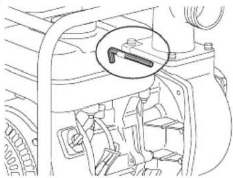
(See Fig. 7-7) 10
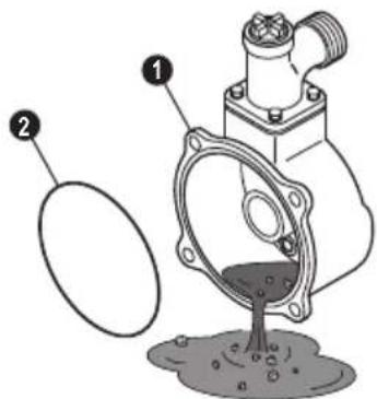
If the inside of the pump is plugged up with small rocks or if the inside of the pump has to be cleaned, you can clean the inside of the pump by removing the casing cover using the Hexagon wrench that comes with the pump.
The accessory Hexagon wrench (8 mm) is attached to the upper part of the casing. (See Fig. 7-7)
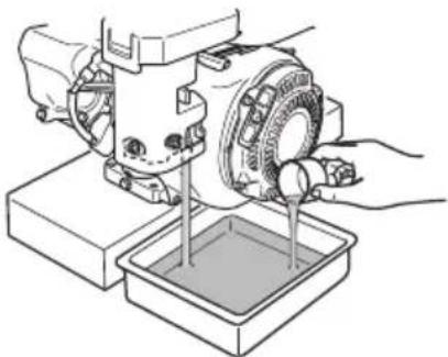
(1) Removal of the casing cover (See Fig. 7-8) Remove the 4 socket bolts.
(2) Cleaning the inside of the pump (See Fig. 7-9) After removing the pebbles and dirt from the inside of the pump, rinse it out with clean water.
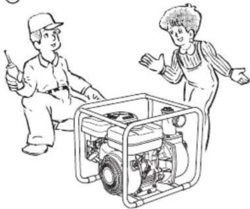
Explanation of Fig. 7 ⑨
① Casing cover O-Ring ②
Make sure not to damage the O-ring as this will cause water leakage.
If the O-ring is deteriorated or damaged, replace it with a new one.
(3) Reattaching the casing cover (See Fig. 7-10) Tighten the 4 socket bolts.
6. PREPARATIONS FOR STORAGE
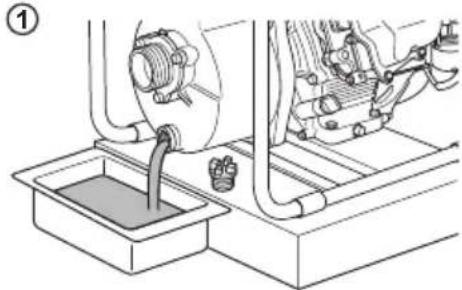
1. WATER (See Fig. 8)①
Drain all water from the drain plug.
CAUTION
When retightening drain plug, be sure to clean the drain plug and the thread of casing. Otherwise, the thread may be damaged.
2. DISCONNECT THE DELIVERY HOSE
Tilt the pump and drain all water from delivery hole. Severe damage to pump may result if water freezes in the pumping chamber.
3. DISCHARGE FUEL
(See Fig. 8)②
WARNING
Flame Prohibited
If you do not use the engine more than 1 month, discharge fuel to prevent gum in the fuel system and carburetor parts.
WARNING
Remove the statistic electricity from your body before refilling the gasoline. Sparking from electrostatic discharge may cause the ignition to the vaporized fuel (gasoline) resulting burns.
Static electricity can be discharged from the body by touching by hand the meta parts of the unit.
Always store/carry the fuel (gasoline) with metallic portable tank to prevent fire.
■ Remove the strainer cup, place the strainer over a container and open the strainer valve to discharge fuel from the fuel tank.
■ Remove the drain screw of the carburetor float chamber and discharge fuel.
4. ENGINE OIL (See Fig. 8)③
■ Change the engine oil with fresh oil.
■ Remove the spark plug, pour about 5 cc of engine oil into the cylinder, slowly pull the starter handle of the recoil starter 2 or 3 times, and reinstall the spark plug.
5. CLEAN AND STORE
■ Slowly pull the recoil starter handle until resistance is felt and leave it in that position.
■ Clean the pump thoroughly with an oiled cloth, put the cover on, and store the pump indoors in a well ventilated, low humidity area.
7. OIL SENSOR INSTRUCTIONS
1. FUNCTION OF OIL SENSOR
The engine will stop automatically when the oil level falls below the safety limit. The engine cannot be started unless the level is raised above the prescribed limit. (See Fig. 2-4)
2. RESTARTING
(1) Fill the crankcase with oil up to the proper level.
(2) As for restarting and operating the engine, refer to section "4. OPERATING YOUR PUMP" on page 6.
- Check the wire connector from the engine. It must be connected securely to the wire from oil sensor.
■ When selecting the engine oil, refer to page 5 for the recommended oil.
8. EASY TROUBLESHOOTING
1. PUMP DOES NOT RUN.
■ Engine dose not start.
(See "8.-6. WHEN ENGINE DOES NOT START")
■ Sticking of impeller (Disassemble and clean.)
2. PUMPING VOLUME IS SMALL.
■ Sucking air at suction side. (Check piping at suction side.)
■ Drop off engine output.
(Consult your nearest dealer.)
■ Breakage of mechanical seal. (Consult your nearest dealer.)
■ High suction lift (Lower.)
■ Suction hose is too long or thin.
(Use a thick hose in minimum length.)
■ Leak of water from water passage. (Stop leaking.)
■ Clogging of foreign substance in impeller. (Disassemble and clean.)
■ Wear of impeller.
■ Strainer is clogged. (Clean.)
■ Engine speed is too low.
(Consult your nearest dealer.)
3. PUMP DOES NOT SELFPRIME.
■ Suction of air at suction side. (Check piping at suction side.)
■ Insufficient priming water inside pump casing. (Prime fully.)
■ Imperfect tightening of drain plug. (Tighten the plugs completely.)
■ Engine speed is too low.
(Consult your nearest dealer.)
■ Sucking air from mechanical seal. (Consult your nearest dealer.)
4. DELIVERY HOSE DOES NOT STAY ON COUPLING.
■ Hose may be kinked or discharge end may be blocked or clogged. (Straighten or clean.)
5. PUMP SUDDENLY STOPS.
■ Solid object preventing pump-rod from completing stroke. (Disassemble and clean.)
6. WHEN ENGINE DOES NOT START:
Perform the following checks before you take the pump to your Makita dealer. If you still have trouble after completing the checks, take the pump to your nearest Makita dealer.
(1) Is there a strong spark across the electrode?
■ Is the stop switch at position "I" (ON)?
■ Remove and inspect the spark plug.
If the electrode is fouled, clean or replace it with new one.
■ Remove the spark plug and connect it to the plug cap. Pull the starter handle while grounding spark plug against engine body. Try with a new spark plug if the spark is weak or there is no spark.
The ignition system is faulty if there is no spark with a new spark plug.
WARNING
Wipe out spilled fuel carefully before testing. Place spark plug as far away from spark plug hole as possible.
Do not hold spark plug by hand while pulling recoil starter.
NOTE
The engine with oil sensor will stop automatically when the oil level falls below the prescribed limit. Unless the oil level is raised above the prescribed limit, the engine will stop immediately after starting.
(2) Is there enough compression?
Pull the starter handle slowly and check if resistance is felt.
If little force is required to pull the starter handle, check if the spark plug is tightened firmly. If the spark plug is loose, tighten it.
(3) Is the spark plug wet with gasoline?
■ Is the fuel valve opened?
- Choke (close choke lever) and pull the starter handle five or six times. Remove the plug and check if its electrode is wet. If the electrode is wet, fuel is well supplied to your engine.
■ When the electrode is dry, check where the fuel stops. (Check the fuel intake of the carburetor.)
■ In case the engine does not start with well supplied fuel, try using fresh fuel.
9. SPECIFICATIONS
| Model EW2050H EW305 | 50H EW2051H EW305 | 1H | |||
| PUMP | Type Self-priming, Centrifugal pump | Self-priming, Semi Trash pump | |||
| Suction × Delivery Diameters mm 50 | × 50 76 × 76 50 × 50 | 76 × 76 | |||
| Total Head m 32 23 | |||||
| Maximum Delivery Volume Liter/min | 520 1000 700 | 1000 | |||
| Suction Head m 8.0 | |||||
| Axle Seal Material (Mechanical Seal) | Ceramic - carbon | Silicon - carbide | |||
| ENGINE | Model EX16 EX17 | EX16 | EX17 | ||
| Type | Air-Cooled, 4-cycle, OHC, Gasoline Engine | ||||
| Lubricant | Automotive detergent oil(API / SE or higher grade, SG, SH or SJ is recommended. SAE / 10W-30 etc.) | ||||
| Oil Capacity Liter 0.6 | |||||
| Fuel | Automotive unleaded gasoline | ||||
| Fuel Tank Capacity Liter 3.2 | |||||
| Spark plug | TORCH E6RC or NGK BR-6HS | ||||
| Starting system | Recoil starter | ||||
| Dimensions (L × W × H) mm | 527 × 368 × 417 | ||||
| Net Weight kg | 24.9 26.1 24.9 26.1 | ||||
| Standard accessories | Engine tool kit (1 set), Strainer (1 pc.), Hose coupling (2 set), Hose band (3 pcs.), Instruction for use (1 pc.) | Engine tool kit (1 set), Strainer (1 pc.), Hose coupling (2 set), Hose band (3 pcs.), Instruction for use (1 pc.), Hexagon wrench (1 pc.) | |||
- Specifications are subject to change without notice.
10. EC DECLARATION OF CONFORMITY
For European countries only
The EC declaration of conformity is included as Annex A to this instruction manual.
Noise
- Sound pressure level at workstation. (2006/42/EC)
| Brand Name Sound pressure level | The operating condition of the machinery during measurement and the measuring method |
| EW2050H 86 dB(A)EW3050H 89 dB(A)EW2051H 87 dB(A)EW3051H 90 dB(A) | Operating condition: @ 75% loadMeasuring method: At a distance of 1m from the surface of the machinery and at a height of 1.6m from the floor. And the sound pressure value of the direction used as the maximum sound pressure is shown.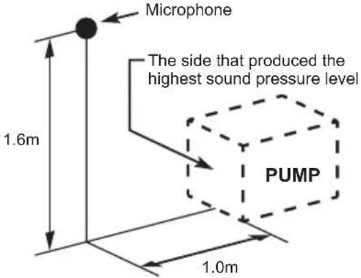 |
- Sound power level (2000/14/EC-2005/88/EC)
| Brand Name Me | Measured Sound Power Level Guaranteed Sound Power Level |
| EW2050H 100 | dB(A) 101 dB(A) |
| EW3050H 103 | dB(A) 103 dB(A) |
| EW2051H 101 | dB(A) 103 dB(A) |
| EW3051H 104 | dB(A) 105 dB(A) |
These noise levels do not necessarily showed a safe working level. However, the user will enable better evaluation of hazard and risk using this information.
Note: The noise level changes with specifications. Specifications may be changed without a preliminary announcement.
Français (Instructions originales)
AVANT-PROPOS
natural_image
Illustration of a person inside a building with smoke and dust clouds (no text or symbols)AVERTISSEMENT
: PRÉCAUTIONS RELATIVES AU PLEIN DE CARBURANT
natural_image
Illustration of a person operating a robotic device with visible gears and wiring (no text or symbols)AVERTISSEMENT
natural_image
Illustration of a person operating a mechanical device with a cross-shaped band (no text or symbols)AVERTISSEMENT
: AUTRES CONSIGNES DE SÉCURITÉ
natural_image
Cartoon illustration of a person falling off a slope with a helmet and gear (no text or symbols)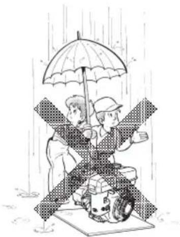
natural_image
Illustration of two people sitting on a platform under an umbrella in the rain (no text or symbols)
natural_image
Cartoon character holding a wrench and a mechanical device (no text or symbols)ATTENTION
: PRENEZ GARDE AUX COUPS DE BÉLIER

natural_image
Illustration of two workers assembling a portable industrial machine (no text or symbols visible)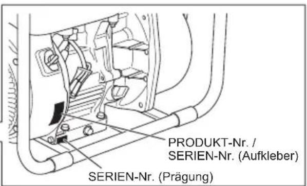
natural_image
Illustration of a person inside a large industrial structure with smoke and dust clouds (no text or symbols)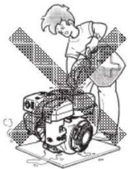
natural_image
Illustration of a person operating a robotic device with rotating wheels (no text or symbols visible)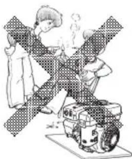
natural_image
Illustration of two people operating a machine with steam rising (no text or symbols)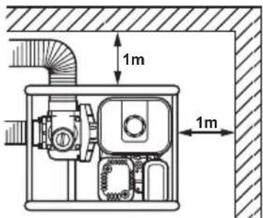
natural_image
Illustration of a person climbing a slope with a helmet and gear (no text or symbols)
natural_image
Illustration of two people under an umbrella in rain, one seated on a vehicle while the other stands (no text or symbols)
natural_image
Cartoon character holding a wrench and a wrench, smiling with open mouth (no text or symbols)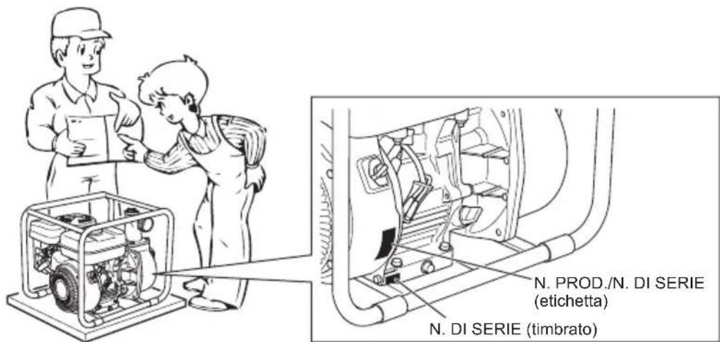
INDICE
Pagina
-
PRECAUZIONI PER LA SICUREZZA....40
-
COMPONENTI 42
-
OPERAZIONI PRELIMINARI PER L'AVVIO ....43
-
USO DELLA POMPA....44
-
MANUTENZIONE 45
-
PREPARATIVI PER LA CONSERVAZIONE 47
-
ISTRUZIONI PER IL SENSORE OLIO 48
-
RISOLUZIONE DEI PROBLEMI SEMPLICI ....48
-
DATI TECNICI 50
-
DICHIARAZIONE DI CONFORMITÀ CE....50
NOTA
natural_image
Illustration of a person inside a large industrial container with smoke rising (no text or symbols)AVVERTIMENTO
: PRECAUZIONI PER IL RIFORNIMENTO DI CARBURANTE
natural_image
Illustration of a person operating a robotic arm with a gear-like structure (no text or symbols visible)AVVERTIMENTO
natural_image
Illustration of a person operating a mechanical device with crossed arms (no text or symbols)AVVERTIMENTO
: ALTRE PRECAUZIONI PER LA SICUREZZA
natural_image
Cartoon illustration of a person falling off a slope with a helmet and gear (no text or symbols)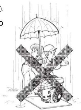
natural_image
Illustration of two people under an umbrella in rain, one holding a large umbrella and the other operating a tractor (no text or symbols)
natural_image
Cartoon character holding a wrench and a wrench, smiling with open mouth (no text or symbols)
INHOUD
Pagina
-
VEILIGHEIDSVOORZORGSMAATREGELEN 53
-
COMPONENTEN 55
-
VOORBEREIDINGEN VOOR HET STARTEN 56
-
DE POMP BEDIENEN....57
-
ONDERHOUD....58
-
VOORBEREIDINGEN VOOR OPSLAG 60
-
INSTRUCTIES VOOR OLIESENSOR....61
-
EENVOUDIG STORINGZOEKEN....61
-
TECHNISCHE GEGEVENS 63
-
EG-VERKLARING VAN CONFORMITEIT 63
OPMERKING
natural_image
Illustration of a person inside a house with smoke and debris, no text or symbols presentWAARSCHUWING
: VEILIGHEIDSVOORZORGSMAATREGELEN BIJ HET TANKEN
natural_image
Illustration of a person working on a robotic device with no visible text or symbolsWAARSCHUWING
: BRANDPREVENTIE
natural_image
Illustration of two people operating a mechanical device with a sprayer, no text or symbols presentWAARSCHUWING
: OVERIGE VEILIGHEIDSVOORZORGSMAATREGELEN
WAARSCHUWING : OPSTARTCONTROLES
natural_image
Illustration of a person climbing a slope with a helmet and gear (no text or symbols)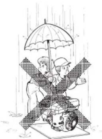
natural_image
Illustration of two people sitting on a vehicle under an umbrella in the rain (no text or symbols)
natural_image
Cartoon character holding a wrench and a mechanical device (no text or symbols)LET OP : KIJK UIT VOOR WATERSLAG
1. WERKING VAN OLIESENSOR
natural_image
Illustration of a person inside a house with smoke and dust clouds (no text or symbols)
ADVERTENCIA
: PRECAUCIONES PARA REPOSTAR
natural_image
Illustration of a person operating a robotic device with visible gears and blades (no text or symbols)
ADVERTENCIA
natural_image
Illustration of a person crossed with a large mechanical device, no text or symbols present
ADVERTENCIA
natural_image
Cartoon illustration of a person falling off a slope with a helmet and gear (no text or symbols)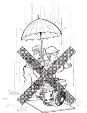
natural_image
Illustration of two people under an umbrella in the rain, one standing and one seated on a platform (no text or symbols)
natural_image
Cartoon character holding a wrench and a mechanical device (no text or symbols)
PRECAUCIÓN
natural_image
Illustration of a person inside a house with smoke and debris, no text or symbols presentAVISO
natural_image
Illustration of a person operating a robotic vehicle with a gear-like structure (no text or symbols visible)AVISO
natural_image
Illustration of two people operating a mechanical device with no visible text or symbolsAVISO
: OUTRAS PRECAUÇÕES DE SEGURANÇA
natural_image
Illustration of a person climbing a slope with a helmet and gear (no text or symbols)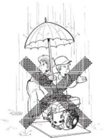
natural_image
Illustration of two children playing with an umbrella in the rain, one standing on a mat and the other holding a tablet (no text or symbols)
natural_image
Cartoon character holding a wrench and a wrench, smiling with open mouth (no text or symbols)PRECAUÇÃO
: TENHA ATENÇÃO AOS GOLPES DE ARÍETE
INDHOLD
Side
-
SIKKERHEDSFORSKRIFTER 92
-
KOMPONENTER 94
-
FORBETJENING TIL START 95
-
BETJENING AF PUMPEN....96
-
VEDLIGEHOLDELSE 97
-
FORBEREDELSE TIL OPBEVARING....99
-
INSTRUKTIONER TIL OLIESENSOR....100
-
NEM FEJLFINDING 100
-
SPECIFICATIONER 102
-
EF-OVERENSSTEMMELSESERKLÆRING.... 102
BEMÆRK
natural_image
Illustration of a person inside a greenhouse with smoke and dust clouds (no text or symbols)ADVARSEL
: FORSKRIFTER VEDR∅RENDE BRÆNDSTOFPÅFYLDNING
natural_image
Illustration of a person operating a robotic device with visible wheels and antenna (no text or symbols)ADVARSEL
: FOREBYGGELSE AF BRAND
natural_image
Illustration of a person operating a mechanical device with crossed bars (no text or symbols)ADVARSEL
: ANDRE SIKKERHEDSFORSKRIFTER
natural_image
Cartoon illustration of a person falling off a slope with a helmet and gear (no text or symbols)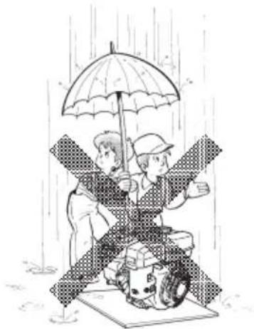
natural_image
Illustration of two people sitting on a platform under an umbrella in the rain (no text or symbols)
natural_image
Cartoon character holding a wrench and a hard hat, smiling with one hand raised (no text or symbols)▲ FORSIGTIG : PAS PÅ VANDSLAG

natural_image
Illustration of a person running inside a house with smoke and debris (no text or symbols)
natural_image
Illustration of a person operating a robotic device with visible gears and blades (no text or symbols)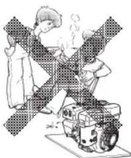
natural_image
Illustration of two people operating a robotic device with a warning symbol (no text or symbols present)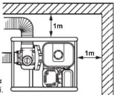
natural_image
Illustration of a person climbing a slope with a helmet and gear (no text or symbols)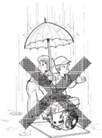
natural_image
Illustration of two people under an umbrella in rain, one holding a motorcycle and the other standing on a platform (no text or symbols)
natural_image
Cartoon character holding a wrench and a mechanical device (no text or symbols)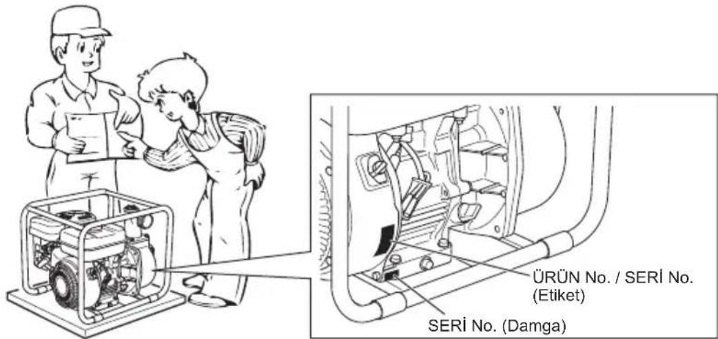
iÇİNDEKİLER
Sayfa
natural_image
Illustration of a person inside a damaged structure with smoke and debris, no text or symbols present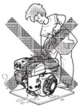
natural_image
Illustration of a person operating a robotic device with a gear-like structure (no text or symbols visible)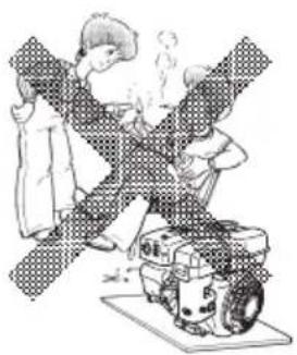
natural_image
Illustration of a person in a suit operating a mechanical device with motion lines (no text or symbols)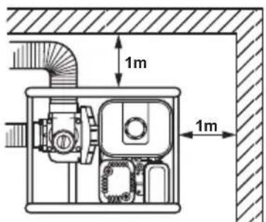
⚠ UYARI : DİĞER GÜVENLİK UYARILARI
natural_image
Cartoon illustration of a person falling off a slope with a helmet and gear (no text or symbols)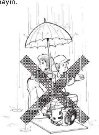
natural_image
Illustration of two people on a robot under an umbrella in the rain (no text or symbols)
natural_image
Cartoon character holding a wrench and a wrench, smiling with open mouth (no text or symbols)⚠ DİKKAT : SU DARBESİNE KARŞI DİKKATLİ OLUN
natural_image
Illustration of a person inside a building with smoke and debris, no text or symbols present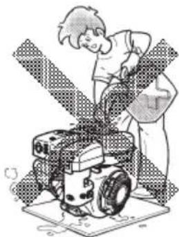
natural_image
Illustration of a person operating a robotic device with wheels and a sensor array (no text or symbols)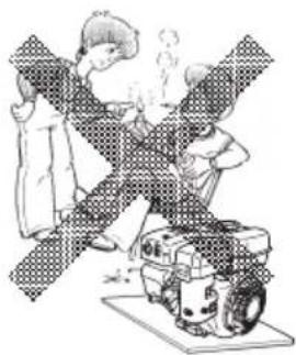
natural_image
Illustration of a person operating a mechanical device with steam rising (no text or symbols)
⚠ OSTRZEŻENIE : POZOSTAŁE ZASADY BEZPIECZEŃSTWA
natural_image
Cartoon illustration of a person climbing a slope with directional arrows (no text or symbols)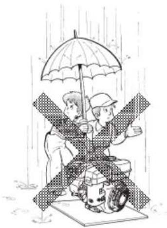
natural_image
Illustration of two people under an umbrella in the rain, one holding a tractor and the other standing on a platform (no text or symbols)
natural_image
Cartoon character holding a wrench and a wrench, smiling with open mouth (no text or symbols)
natural_image
Illustration of a person climbing a slope with scaffolding (no text or symbols)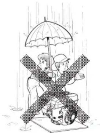
natural_image
Illustration of two people under an umbrella in rain, one seated on a platform with a vehicle nearby (no text or symbols)
natural_image
Cartoon illustration of a smiling robot holding a wrench, no text or symbols presentFIGYELEM! : ELÓZZE MEG A VÍZÜTÉS KIALAKULÁSÁT
natural_image
Illustration of a person inside a house with smoke and debris, no text or symbols present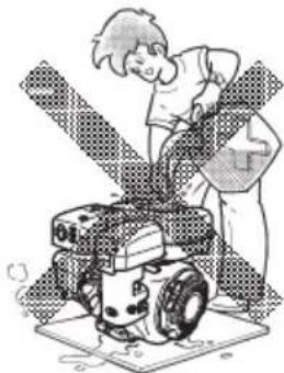
natural_image
Illustration of a person operating a robotic device with visible gears and wheels (no text or symbols)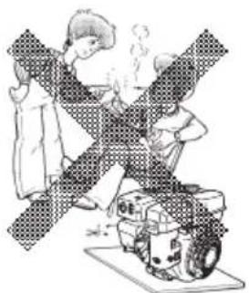
natural_image
Illustration of two people crossed over a machine with steam rising (no text or symbols)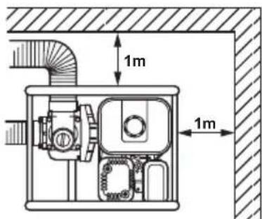

VÝSTRAHA
: ĐALŠIE BEZPEČNOSTNÉ POKYNY
■ Nedovol'te obsluhovat' zariadenie opitým osobám.
■ Dávajte pozor na horúce časti.
natural_image
Cartoon illustration of a person falling off a slope with a vehicle in the background (no text or symbols)natural_image
Illustration of two people under an umbrella in rain, one seated on a vehicle and the other standing, with no visible text or symbols.
natural_image
Cartoon character holding a wrench and a mechanical device (no text or symbols)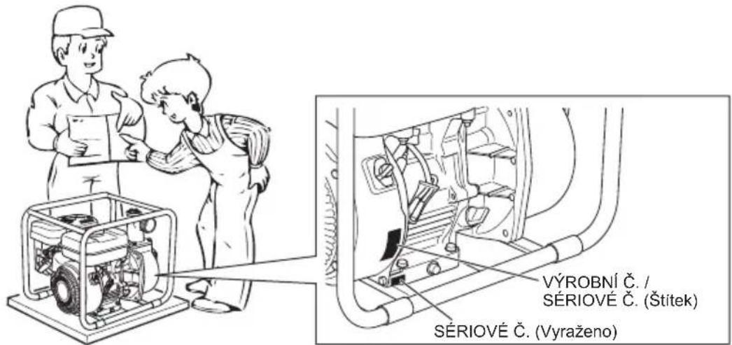
natural_image
Illustration of a person inside a house with smoke and steam rising (no text or symbols)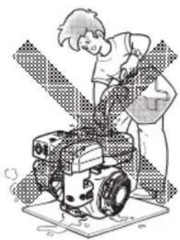
natural_image
Illustration of a person operating a tracked robot with gear and wheels (no text or symbols)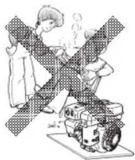
natural_image
Illustration of two people working on a mechanical device with motion lines indicating movement (no text or symbols)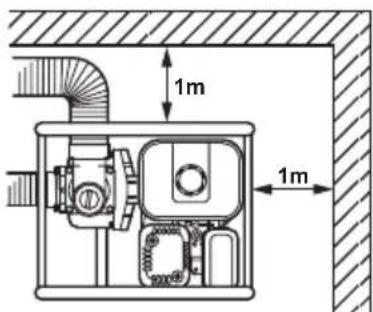
VAROVÁNÍ
: DALŠÍ BEZPEČNOSTNÍ OPATŘENÍ
natural_image
Cartoon illustration of a person in motion with arms raised, surrounded by abstract geometric shapes (no text or symbols)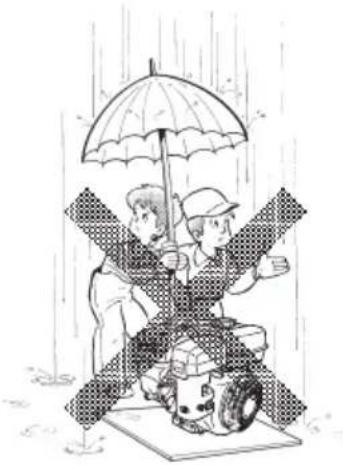
natural_image
Illustration of two people on a tractor under an umbrella in the rain (no text or symbols)
natural_image
Cartoon character holding a wrench and a wrench, smiling with open mouth (no text or symbols)SYMBOLY
6. KDYŽ MOTOR NESTARTUJE:
natural_image
Illustration of a person inside a house with smoke and debris, no text or symbols present
natural_image
Illustration of a person operating a robotic device with a gear-like structure (no text or symbols visible)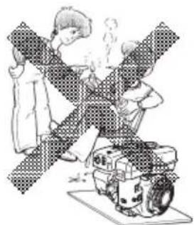
natural_image
Illustration of a person operating a mechanical device with crossed-out beams (no text or symbols)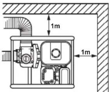
OPOZORILO : DRUGI VARNOSTNI UKREPI
natural_image
Illustration of a person in a seatbelt with arms crossed, no text or symbols presentnatural_image
Illustration of two people sitting on a platform under an umbrella in the rain (no text or symbols)
natural_image
Cartoon character holding a wrench and a mechanical device (no text or symbols)⚠️ POZOR : PREPREČITE VODNI SUNEK

PËRMBAJTJA
Faqja
- MASA PARAPRAKE TË SIGURISË 193
- PJESËT PËRBËRËSE 195
- PARAPËRGATITJA PËR NDEZJE. 196
- PËRDORIMI I POMPËS 197
- MIRËMBAJTJA 198
- PËRGATITJET PËR MAGAZINIM....200
- UDHËZIMET PËR SENSORIN E VAJIT .....200
8.ZGJIDHJA E LEHTË E PROBLEMEVE 201 - SPECIFIKIMET 202
- DEKLARATA E KONFORMITETIT ME KE-NË 202
SHËNIM
natural_image
Illustration of a person inside a house with smoke and debris, no text or symbols present
natural_image
Illustration of a person operating a robotic device with wheels and a gear (no text or symbols)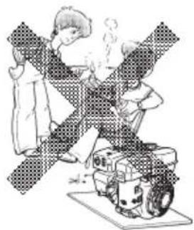
natural_image
Illustration of two people operating a machine with steam rising (no text or symbols)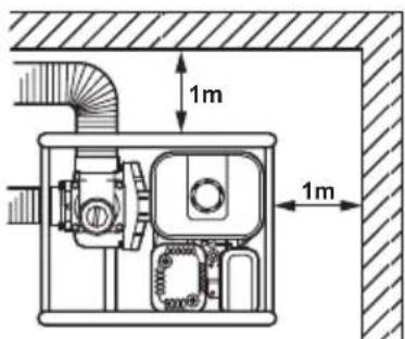
⚠️ PARALAJMËRIM : MASA PARAPRAKE SIGURIE TË TJERA
KUJDES : RUHUNI NGA GODITJA E UJIT
natural_image
Illustration of a person in motion with arms crossed, no text or symbols present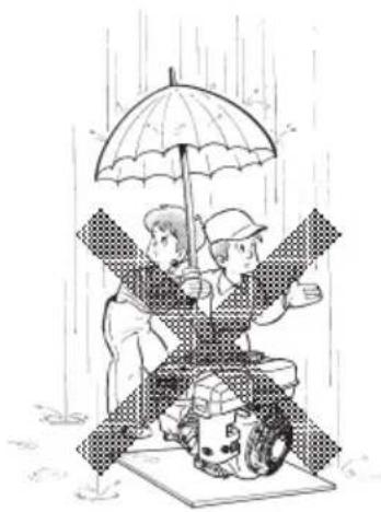
natural_image
Illustration of two people under an umbrella in the rain, one seated on a tractor and the other standing (no text or symbols)
natural_image
Cartoon character holding a wrench and a wrench, smiling with open mouth (no text or symbols)
СЪДЪРЖАНИЕ
Страница
natural_image
Illustration of a person inside a house with smoke and debris, no text or symbols present
natural_image
Illustration of a person operating a robotic device with a gear-like structure (no text or symbols visible)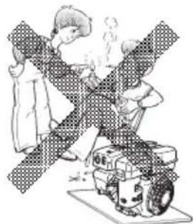
natural_image
Illustration of two people operating a mechanical device with a cross-shaped structure (no text or symbols)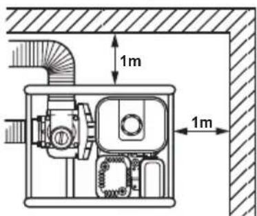
natural_image
Cartoon illustration of a person falling off a slope with a flag, no text or symbols present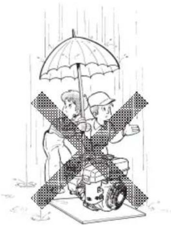
natural_image
Illustration of two people sitting on a robot under an umbrella in the rain (no text or symbols)
natural_image
Cartoon character holding a wrench and a hard hat, smiling with open arms (no text or symbols)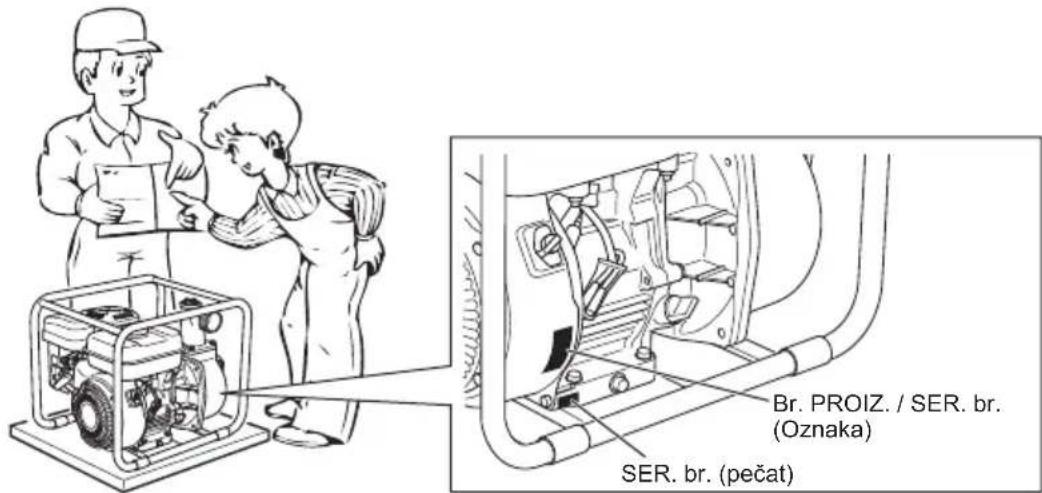
SADRŽAJ
Stranica
- MJERE PREDOSTROŽNOSTI .....218
- DIJELOVI....220
- PREDRADNJE ZA POKRETANJE .....221
- RUKOVANJE CRPKOM .....222
- ODRŽAVANJE....223
- PRIPREME ZA POHRANJIVANJE .....225
- UPUTE ZA SENZOR ZA ULJE .....225
- RJEŠAVANJE JEDNOSTAVNIH PROBLEMA....226
- SPECIFIKACIJE .....227
- EZ IZJAVA O SUKLADNOSTI .....227
NAPOMENA
Pogledajte ilustracije na poleđini naslovnice za slike 1 do 8 navedene u rečenici.
natural_image
Illustration of a person inside a house with smoke and steam rising (no text or symbols)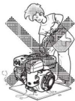
natural_image
Illustration of a person operating a tracked robot with a radar dish (no text or symbols visible)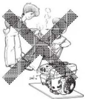
natural_image
Illustration of a person assembling or repairing a mechanical device with a crossed-out band (no text or symbols)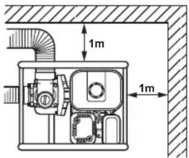
⚠ UPOZORENJE : OSTALE MJERE PREDOSTROŽNOSTI
natural_image
Cartoon illustration of a person climbing a slope with a helmet and gear (no text or symbols)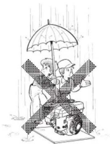
natural_image
Illustration of two people under an umbrella in rain, one seated on a platform with a vehicle, the other standing nearby (no text or symbols)
natural_image
Cartoon character holding a wrench and a hard hat, smiling with open arms (no text or symbols)SIMBOLI
 | Pročitajte priručnik. |  | Isključite ventil za gorivo kad se motor ne koristi. |
 | Držite se podalje od vruće površine. | 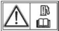 | Provjerite cure li crijevo i spojni dijelovi. |
| Ispušni plin je otrovan.Nemojte raditi u neprovjetrenoj prostoriji ili zatvorenom području. |  | Vatra, otvoreni plamen i pušenje je prečistač. |
| Motor zaustavite prije dolijevanja goriva. | | VRUĆE, nemojte dodirivati vrući dio. |
| Uključeno(Pokretanje) | Pokretanjemotora (električnopokretanje) | Gorivo (benzin) Startna pumpa | |||||
 | Isklj. (Stop) |  | Zaustavljanjemotora |  | Gorivo (dizel) |  | Pritisni startnupumpu |
 | Motorno ulje Hladan m |  |  | Isključivanjedovoda goriva |  | Ne pritišći startnupumpu | |
 | Dodavanje ulja Topao |  r r |  | Kvar / neispravnostsustava za gorivo |  | Dva puta | |
 | Baterija |  | Električno predgrijavanje(Pomoć za pokretanjekod niske temperature) |  | Čok | ||
 | Brzo |  | Položaj zapokretanje |  | Plus;pozitivni pol | ||
 | Sporo |  | Položaj zazaustavljanje |  | Minus;negativni pol |
2. DIJELOVI
(Pogledajte sliku)
NAPOMENA
Pogledajte ilustracije na poledini naslovnice za slike 1 do 8 navedene u rečenici.
5. CRPKA SE NAGLO ZAUSTAVLJA.
natural_image
Illustration of a person inside a house with smoke and debris, no text or symbols presentПРЕДУПРЕДУВАЊЕ
natural_image
Illustration of a person operating a robotic device with visible gears and wheels (no text or symbols)ПРЕДУПРЕДУВАЊЕ
: СПРЕЧУВАЊЕ ПОЖАР
natural_image
Illustration of a person operating a machine with a large cross-shaped device (no text or symbols visible)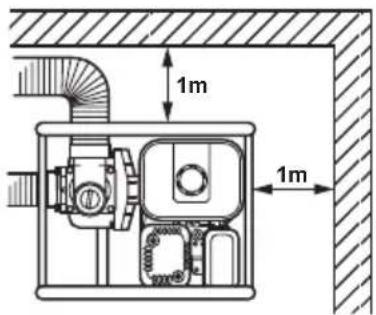
ПРЕДУПРЕДУВАЊЕ
natural_image
Illustration of a person climbing a slope with directional arrows, no text or symbols present
natural_image
Illustration of two people under an umbrella in the rain, one standing on a vehicle and the other holding a tablet (no text or symbols present)
natural_image
Cartoon character holding a wrench and a mechanical device (no text or symbols)

natural_image
Cartoon illustration of a person inside a house with smoke and debris, no text or symbols present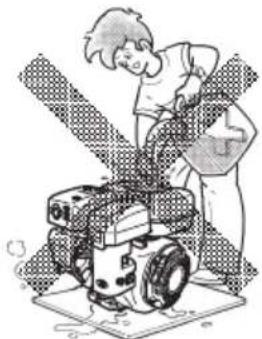
natural_image
Illustration of a person operating a robotic device with visible gears and wheels (no text or symbols)
natural_image
Illustration of two people working on a mechanical device with no visible text or symbols
AVERTISMENT : ALTE MĂSURI DE SIGURANTĂ
natural_image
Cartoon illustration of a person climbing a slope with a helmet and gear (no text or symbols)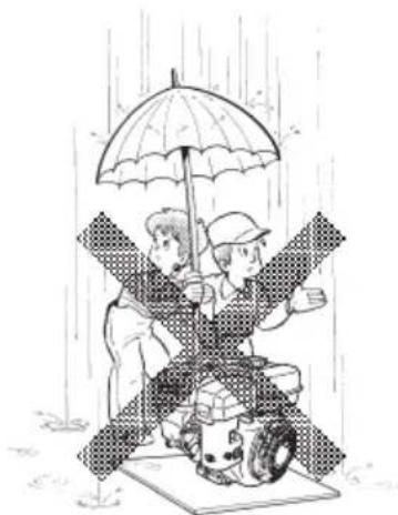
natural_image
Illustration of two people under an umbrella in rain, one holding a large umbrella and the other sitting on a tractor (no text or symbols)
natural_image
Cartoon illustration of a smiling robot holding a wrench and a wrench, with no text or symbols present.
САДРЖАЈ
Страна
-
БЕЗБЕДНОСНЕ МЕРЕ ПРЕДОСТРОЖНОСТИ.... 255
-
KOMПОНЕНТЕ.... 257
-
РАДЊЕ ПРЕ ПОКРЕТАЊА 258
-
РУКОВАЊЕ ПУМПОМ.... 259
-
ОДРЖАВАНЬЕ..... 260
-
ПРИПРЕМЕ ЗА СКЛАДИШТЕЊЕ.... 262
-
УПУСТВА ЗА СЕНЗОР УЛЬА 262
-
ЈЕДНОСТАВНО РЕШАВАЊЕ ПРОБЛЕМА 263
-
СПЕЦИФИКАЦИЈЕ....264
-
ЕЗ ДЕКЛАРАЦИЈА О УСКЛАЂЕНОСТИ. 264
НАПОМЕНА
natural_image
Cartoon illustration of a person inside a house with smoke rising from the windows (no text or symbols)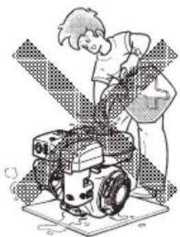
natural_image
Illustration of a person operating a robotic device with visible gears and wheels (no text or symbols)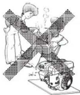
natural_image
Illustration of a person operating a robotic device with smoke, no text or symbols present
⚠️ УПОЗОРЕЊЕ : ДРУГЕ МЕРЕ ПРЕДОСТРОЖНОСТИ
natural_image
Illustration of a person in motion with arms crossed, no text or symbols present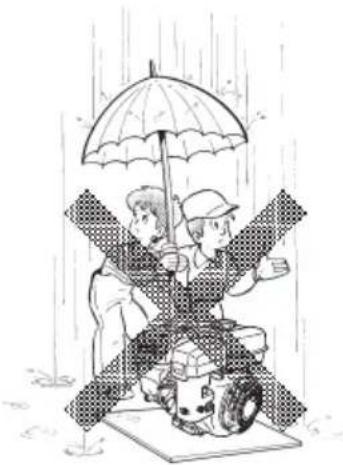
natural_image
Illustration of two people sitting on a platform under an umbrella in the rain (no text or symbols)
natural_image
Cartoon character holding a wrench and a wrench, smiling with open mouth (no text or symbols)⚠️ ОПРЕЗ : ПАЗИТЕ НА ХИДРАУЛИЧНИ УДАР
natural_image
Illustration of a person inside a house with smoke and steam rising (no text or symbols)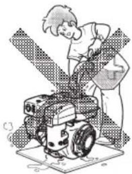
natural_image
Illustration of a person operating a robotic device with a gear-like structure (no text or symbols visible)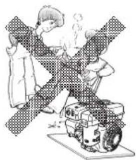
natural_image
Illustration of a person operating a machine with steam rising (no text or symbols)
natural_image
Cartoon illustration of a person climbing a slope with arms crossed (no text or symbols)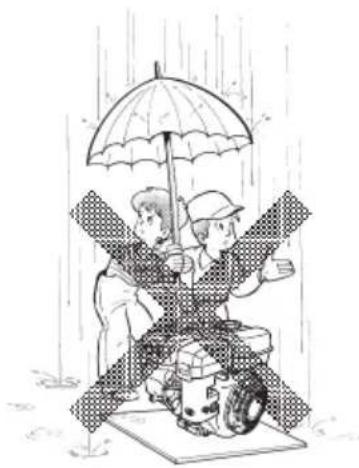
natural_image
Illustration of two people sitting on a wet surface under an umbrella, with a vehicle nearby (no text or symbols)
natural_image
Cartoon character holding a wrench and a mechanical device (no text or symbols)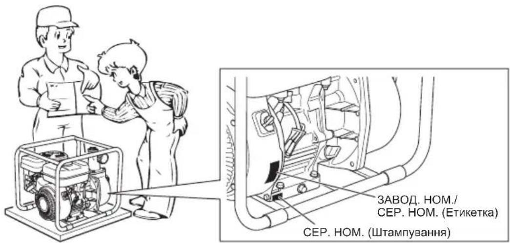
3MICT
Сторінка
natural_image
Illustration of a person inside a building with smoke and dust clouds (no text or symbols)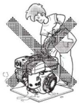
natural_image
Illustration of a person operating a small wheeled robot on a mat (no text or symbols visible)
natural_image
Illustration of a person operating a mechanical device with a warning symbol (no text or symbols present)
ПОПЕРЕДЖЕННЯ
natural_image
Cartoon illustration of a person falling off a slope with a vehicle in the background (no text or symbols)
natural_image
Illustration of two people sitting on a vehicle under an umbrella in heavy rain (no text or symbols)
natural_image
Cartoon character holding a wrench and a hard hat, smiling with one hand raised (no text or symbols)3-11-8, Sumiyoshi-cho,
Anjo, Aichi 446-8502 Japan
EW2050H-23L-0216
www.makita.com
IDE


- English (Original instructions)
- FOREWORD
- CONTENTS
- Page
- NOTE
- SAFETY PRECAUTIONS
- WARNING
- CAUTION
- WARNING : EXHAUST PRECAUTIONS
- WARNING : REFUELING PRECAUTIONS
- WARNING : FIRE PREVENTION
- WARNING : OTHER SAFETY PRECAUTIONS
- WARNING : PRE-OPERATION CHECKS
- CAUTION : BEWARE OF WATER-HAMMERING
- SYMBOLS
- COMPONENTS
- (See Fig.)
- PRE-OPERATION FOR STARTING
- (See Fig. 2)
- CONNECT SUCTION HOSE (See Fig. 2)①
- CONNECT DELIVERY HOSE (See Fig.2-2)
- CHECK ENGINE OIL (See Fig. 2)④
- Explanation of Fig. 2④
- CHECK FUEL (See Fig. 2-5)
- NOTE THIS ENGINE IS CERTIFIED TO OPERATE ON AUTOMOTIVE UNLEADED GASOLINE.
- Explanation of Fig. 2 ⑤
- CHECK PRIMING WATER (See Fig. 2)⑦
- RUNNING (See Fig. 4)
- STOPPING (See Fig. 5)
- ※ STOPPING ENGINE WITH THE FUEL VALVE
- MAINTENANCE
- (See Fig. 8)
- DAILY INSPECTION
- PERIODIC INSPECTION
- INSPECTING THE SPARK PLUG
- ENGINE OIL CHANGE (See Fig. 7, 2) ③
- CLEANING FUEL CUP (See Fig. 7)④
- Flame Prohibited
- CLEANING AIR CLEANER (See Fig. 7)⑤
- FUEL HOSE REPLACEMENT (See Fig. 7)⑥
- CHECKING BOLTS, NUTS AND SCREWS
- CLEANING PUMP INSIDE
- PREPARATIONS FOR STORAGE
- WATER (See Fig. 8)①
- DISCONNECT THE DELIVERY HOSE
- DISCHARGE FUEL
- ENGINE OIL (See Fig. 8)③
- CLEAN AND STORE
- OIL SENSOR INSTRUCTIONS
- FUNCTION OF OIL SENSOR
- RESTARTING
- EASY TROUBLESHOOTING
- PUMP DOES NOT RUN.
- PUMPING VOLUME IS SMALL.
- PUMP DOES NOT SELFPRIME.
- DELIVERY HOSE DOES NOT STAY ON COUPLING.
- PUMP SUDDENLY STOPS.
- WHEN ENGINE DOES NOT START:
- Is there a strong spark across the electrode?
- Is there enough compression?
- Is the spark plug wet with gasoline?
- SPECIFICATIONS
- EC DECLARATION OF CONFORMITY
- Noise
- Français (Instructions originales)
- AVANT-PROPOS
- AVERTISSEMENT
- : PRÉCAUTIONS RELATIVES AU PLEIN DE CARBURANT
- : AUTRES CONSIGNES DE SÉCURITÉ
- ATTENTION
- : PRENEZ GARDE AUX COUPS DE BÉLIER
- INDICE
- NOTA
- AVVERTIMENTO
- : PRECAUZIONI PER IL RIFORNIMENTO DI CARBURANTE
- : ALTRE PRECAUZIONI PER LA SICUREZZA
- INHOUD
- OPMERKING
- WAARSCHUWING
- : VEILIGHEIDSVOORZORGSMAATREGELEN BIJ HET TANKEN
- : BRANDPREVENTIE
- : OVERIGE VEILIGHEIDSVOORZORGSMAATREGELEN
- WAARSCHUWING : OPSTARTCONTROLES
- LET OP : KIJK UIT VOOR WATERSLAG
- WERKING VAN OLIESENSOR
- ADVERTENCIA
- : PRECAUCIONES PARA REPOSTAR
- PRECAUCIÓN
- AVISO
- : OUTRAS PRECAUÇÕES DE SEGURANÇA
- PRECAUÇÃO
- : TENHA ATENÇÃO AOS GOLPES DE ARÍETE
- INDHOLD
- Side
- BEMÆRK
- ADVARSEL
- : FORSKRIFTER VEDR∅RENDE BRÆNDSTOFPÅFYLDNING
- : FOREBYGGELSE AF BRAND
- : ANDRE SIKKERHEDSFORSKRIFTER
- ▲ FORSIGTIG : PAS PÅ VANDSLAG
- iÇİNDEKİLER
- Sayfa
- ⚠ UYARI : DİĞER GÜVENLİK UYARILARI
- ⚠ DİKKAT : SU DARBESİNE KARŞI DİKKATLİ OLUN
- ⚠ OSTRZEŻENIE : POZOSTAŁE ZASADY BEZPIECZEŃSTWA
- FIGYELEM! : ELÓZZE MEG A VÍZÜTÉS KIALAKULÁSÁT
- VÝSTRAHA
- : ĐALŠIE BEZPEČNOSTNÉ POKYNY
- VAROVÁNÍ
- : DALŠÍ BEZPEČNOSTNÍ OPATŘENÍ
- SYMBOLY
- KDYŽ MOTOR NESTARTUJE:
- OPOZORILO : DRUGI VARNOSTNI UKREPI
- ⚠️ POZOR : PREPREČITE VODNI SUNEK
- PËRMBAJTJA
- Faqja
- SHËNIM
- ⚠️ PARALAJMËRIM : MASA PARAPRAKE SIGURIE TË TJERA
- KUJDES : RUHUNI NGA GODITJA E UJIT
- СЪДЪРЖАНИЕ
- SADRŽAJ
- Stranica
- NAPOMENA
- ⚠ UPOZORENJE : OSTALE MJERE PREDOSTROŽNOSTI
- SIMBOLI
- DIJELOVI
- (Pogledajte sliku)
- CRPKA SE NAGLO ZAUSTAVLJA.
- ПРЕДУПРЕДУВАЊЕ
- : СПРЕЧУВАЊЕ ПОЖАР
- AVERTISMENT : ALTE MĂSURI DE SIGURANTĂ
- САДРЖАЈ
- Страна
- НАПОМЕНА
- ⚠️ УПОЗОРЕЊЕ : ДРУГЕ МЕРЕ ПРЕДОСТРОЖНОСТИ
- ⚠️ ОПРЕЗ : ПАЗИТЕ НА ХИДРАУЛИЧНИ УДАР
- 3MICT
- Сторінка
- ПОПЕРЕДЖЕННЯ
Brand : MAKITA
Model : EW2051H
Category : Water pump