Master 700 - Saw WOLFCRAFT - Free user manual and instructions
Find the device manual for free Master 700 WOLFCRAFT in PDF.
User questions about Master 700 WOLFCRAFT
0 question about this device. Answer the ones you know or ask your own.
Ask a new question about this device
Download the instructions for your Saw in PDF format for free! Find your manual Master 700 - WOLFCRAFT and take your electronic device back in hand. On this page are published all the documents necessary for the use of your device. Master 700 by WOLFCRAFT.
USER MANUAL Master 700 WOLFCRAFT
- CAUTION! Read all the safety information and instructions that were supplied with the MASTER 700 and the power tools used.
Failure to comply with safety information and instructions can lead to electric shock, fire and/or serious injury. - Keep the manual in a safe place for future reference.
TECHNICAL DATA
Dimensions when fully assembled: 680 × 585 × 780 - 950 mm (width x depth x height)
Dimensions when folded up: 680 × 180 × 950 ~mm
Tilt of table surface: 0^ - max. 70^
Clamping area between clamping jaws: max. 130 mm
Bore diameter of clamping bores: 20.2mm
Maximum load: 150 kg
Weight: 14.8kg
SYMBOLS AND MEANINGS

Warning of general danger

General information

Read instructions/information.

Do not apply weight unevenly.

Wear safety goggles.

Maximum load: 150kg

Wear ear protection.

Do not use as a seat, ladder or support.

Wear a dust mask.

Do not stand on the working table.

Pull out mains plug
ASSEMBLY TOOL

2 Allen keys: SW 4 (included in scope of delivery)

1 screwdriver: PH 2 (not included in scope of delivery)

2 hexagonal key: SW 10, 13 (not included in scope of delivery)
INTENDED USE
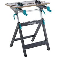
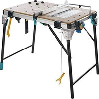
The MASTER 700 is a height-adjustable clamping and working table.
- It is suitable for use as a working table for machining workpieces (e.g. drilling, sanding, etc.).
- The working table allows workpieces to be clamped between the clamping jaws.
- The additional clamping boards allow larger workpieces to be clamped.
The height of the working table can be adjusted between 780 and 950mm and the tilt of the table top can be varied between 0^ and max. 70^ . - Mitre saws or drill stands may only be mounted on the working table using the fastening screws supplied.
CAUTION: It is only possible to use machines on which the workpiece is processed vertically from top to bottom.
CAUTION: Machines that apply lateral pressure to the working table should not be mounted. - Observe the manufacturer's safety instructions for the machines used, as well as the safety instructions for the working table.
- When disposing of the MASTER 700, please observe local disposal regulations.
The user is liable for any damage or accidents resulting from improper use.
SAFETY INFORMATION
- Assemble the working table correctly and check that all the handle screws and screw joints are tight before starting to work. Correct assembly ensures that the table does not fold up and the table plate does not tilt unintentionally.
- Never use your working table improperly or for an unintended purpose!
- Remove all items that are surplus to requirements from the working table.
Make sure that your hands do not get caught in the folding, sliding or tilting parts of the working table. Risk of injury! - Never work with a defective working table!
- Clamp the workpiece to be processed firmly!
- Make sure that all screws and handle screws are tight during transport.
- Place the working table on a firm, level and horizontal surface. If the working table can slip or wobble, the workpiece or power tool cannot be controlled evenly and safely.
- Make sure that both eccentric levers are always tightened so that the height of the table cannot change.
- Assemble the working table correctly before mounting the power tool.
- Fasten the power tool securely on the working table before using it. If the power tool slips on the working table, this can lead to loss of control.
Make sure that the power tool is mounted centrally on the working table. If the power tool is not centred on the working table, this can mean the centre of gravity of the power tool does not align with the centre of gravity of the working table, so that the table can tip over.
Make sure that long workpieces do not bring the working table out of balance. Long workpieces must be supported at the free end. - Wear suitable personal protective equipment: ear protection, safety goggles, dust mask (if the work generates dust), protective gloves when working with rough materials and when changing tools.
- Do not store the working table outdoors or in a damp environment. There is a risk of corrosion and the work top may warp.
- Make sure to follow the instructions and safety information supplied in the original operating instructions for the power tool used. The machines used must comply with DIN EN 60745-1. Devices manufactured after 1995 must carry a CE symbol.
- Keep your work area clean and well lit. Untidy or dark work areas can lead to accidents.
- Keep children and other persons at a safe distance when using the working table. If you are distracted, you may lose control of the device.
- Remove the adjusting tools or spanners before switching on the power tool. A tool or spanner left behind in a rotating part of the device can cause injury.
- Wear suitable clothing. Never wear loose clothing or jewellery. Keep hair, clothing and gloves away from moving parts. Loose clothing, jewellery or long hair can get caught in moving parts.
- Before starting work, check that the devices and tools are operational. Never work with damaged or blunt tools.
- Disconnect the plug from the electric socket and/or remove the battery pack from the power tool before adjusting the tool or changing the accessories. Accidents may occur if the power tool is started unintentionally.
- Avoid overloading the working table and never use it as a seat, ladder or support. Placing excess weight on the machine table or even standing on it can cause the centre of gravity of the table to shift, so that it tips over.
- Loose fragments, chips or similar materials should not be removed by hand from the area around the moving saw blade.
- Make sure that there are no objects on the worktop each time you start sawing.
- Saw blades must not be stopped by applying lateral pressure after switching off the drive mechanism!
- Only use tools for their actual intended purpose.
- Only use saw blades that are in perfect condition.
- Only use genuine wolfcraft spare parts.
- CAUTION: There is a risk of tipping in the case of protruding workpieces.
SCOPE OF DELIVERY
Take the MASTER 700 out of the cardboard box and check whether the contents are complete and all illustrated parts are included (Fig. 1).
ASSEMBLY
Place the lower section of the table on a flat, clean surface (Fig. 2.1). - Make sure that both eccentric levers on the table legs are pressed down, so that the telescopic adjustment is fixed. Then open the footpiece as far as possible until the two securing pins engage (Fig. 2.2).
CAUTION: Make sure that both securing pins are engaged before starting work, so that the table cannot fold up.
CAUTION: Make sure that both eccentric levers are pressed down before starting work, so that the worktop is fixed in place!
Insert the two end stops in the telescopic tubes. Mount the two cross bars as shown. The screw joints with sleeve nut, allen screw and washer should only be tightened enough to allow the cross bars still to pivot. Then mount the two handle screws, washers and screws. Tighten the two handle screws (Figs. 2.3 - 2.5).
CAUTION: Before starting work or making adjustments, make sure that both handle screws are tight so that the tiltable worktop plate cannot slip.
Mount the front table plate as illustrated. Only tighten the screws enough to allow the table plate to be adjusted using the hand cranks (Fig. 2.6).
Fit the rear table plate as illustrated (Fig. 2.7). Position the table plate with the 4 spacers on the cross bars. Then fasten the two rear screw joints. Insert the two screws and washers into the front bores.
Tilt the worktop plate by first loosening the two handle screws, then tilting the table plate to the limit stop and then tightening the two handle screws again (Figs. 2.8 - 2.9).
Fit the two remaining screws using the two washers and nuts (Fig. 2.10).
Now bring the table plate into the horizontal position again by loosening the two handle screws, then tilting the table plate to the limit stop and then tightening the two handle screws again to fix the table plate. Attach the four cover caps (Figs. 2.11 - 2.13). The table is now ready for use.
CAUTION: Before starting work, always make sure that the two eccentric levers for adjusting the height are fastened, the two handle screws for tilting the table plate are tightened and the two securing pins for folding up the table are engaged.
OPERATION
Folding up the table
Press down both eccentric levers on the table legs, so that the height adjustment is fixed. Then loosen the two handle screws and tilt the worktop as far as the limit stop. Tighten the two handle screws again (Figs. 3.1 - 3.2). Now pull the release bar upwards in the direction of the arrow as shown to unlock the locking mechanism. Fold the footpiece against the table legs to the limit stop (Figs. 3.3 - 3.4). The table can be carried with one hand in the middle of the grip bar. For storage, lean the table against a wall at a slight angle to prevent it from falling over (Figs. 3.5 - 3.6).
Folding out the table
Check that both eccentric levers are pressed down, so that the height adjustment is fixed. Then check that the two handle screws for tilting the worktop are tightened (Fig. 4.1). Fold out the footpiece to the limit stop. The right and left securing pins must engage in front of the traverse and telescope, so that the table cannot fold up (Fig. 4.2).
CAUTION: Before starting work, make sure that the footpiece is folded out fully and the two securing pins are engaged.
Then loosen the two handle screws to tilt the table plate. Pivot the worktop to the limit stop and then tighten the two handle screws again (Figs. 4.3 and 4.4).
CAUTION: Before starting work, make sure that both handle screws are tightened so that the worktop cannot tilt and is securely fixed.
Table height adjustment
First check that the two handle screws are tightened. Loosen both eccentric levers in the direction of shown by the arrow (Fig. 5.1). You can now adjust the table to five different positions at a height of between 780 and 950mm . Pull the worktop towards you until the positioning bores of the securing screws are free. The worktop can then After this, the table top can be adjusted to the required height. Reattach the worktop in the positioning bores and press down the two eccentric levers onto the table legs to fix the worktop (figures 5.2 - 5.5).
Tilting the table plate
CAUTION: Any mounted devices, tools and workpieces must be removed from the working table before tilting the table plate.
First make sure that both eccentric levers for adjusting the height are tightened so that the height of the table cannot change. Loosen the two handle screws. The worktop can now be tilted at an angle of between 0^ and 70^ . To fix the worktop, tighten the two handle screws again (Figs. 6.1 and 6.3).
Operating functions
Turn the two hand cranks clockwise to clamp a workpiece. Turn the two hand cranks anti-clockwise to release the workpiece.
The clamping boards included in the scope of delivery offer you a wide range of clamping and support options for workpieces (Fig. 7).
The four additional support tips are inserted into the clamping boards as shown and secured by twisting them to the side.
Device assembly
CAUTION: Before mounting devices, the table plate must be in the horizontal position and firmly fixed with both handle screws. No devices should be installed if the table plate is set at an angle.
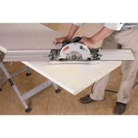
Mitre saws may be mounted on the working table using the fastening screws in the scope of delivery. Place the litre saw in the centre of the table with the mounting bores aligned with the slots of the two table plates. The front table plate can be extended or retracted until the slots are positioned beneath the front mounting bores. Now secure the litre saw. To do this insert the four screws and the four small washers through the mounting bores and table plates from above. Fasten it from below using the large washers and nuts. Check once again that the litre saw is mounted in the centre of the table, so that the centre of gravity of the saw is in the middle and the table cannot tip over (Fig. 8).
CAUTION: Before starting work, always check that all four screw joints are securely fastened.
Height compensation
The height of the table can be adjusted by approx. + / - 3.5mm on uneven surfaces. To achieve this, adjust the height of the two milled screws until the table stands firm and does not wobble (Fig. 9).
CAUTION: Before starting work, make sure that the footpiece is folded out fully and the two securing pins are engaged.
Then loosen the two handle screws to tilt the table plate. Pivot the worktop to the limit stop and then tighten the two handle screws again (Figs. 4.3 and 4.4).
CAUTION: Before starting work, make sure that both handle screws are tightened so that the worktop cannot tilt and is securely fixed.
Table height adjustment
First check that the two handle screws are tightened. Loosen both eccentric levers in the direction of shown by the arrow (Fig. 5.1). You can now adjust the table to five different positions at a height of between 780 and 950mm . Pull the worktop towards you until the positioning bores of the securing screws are free. The worktop can then After this, the table top can be adjusted to the required height. Reattach the worktop in the positioning bores and press down the two eccentric levers onto the table legs to fix the worktop (figures 5.2 - 5.5).
Tilting the table plate
CAUTION: Any mounted devices, tools and workpieces must be removed from the working table before tilting the table plate.
First make sure that both eccentric levers for adjusting the height are tightened so that the height of the table cannot change. Loosen the two handle screws. The worktop can now be tilted at an angle of between 0^ and 70^ . To fix the worktop, tighten the two handle screws again (Figs. 6.1 and 6.3).
Operating functions
Turn the two hand cranks clockwise to clamp a workpiece. Turn the two hand cranks anti-clockwise to release the workpiece. The clamping boards included in the scope of delivery offer you a wide range of clamping and support options for workpieces (Fig. 7). The four additional support tips are inserted into the clamping boards as shown and secured by twisting them to the side.
Device assembly
CAUTION: Before mounting devices, the table plate must be in the horizontal position and firmly fixed with both handle screws. No devices should be installed if the table plate is set at an angle.
Mitre saws may be mounted on the working table using the fastening screws in the scope of delivery. Place the litre saw in the centre of the table with the mounting bores aligned with the slots of the two table plates. The front table plate can be extended or retracted until the slots are positioned beneath the front mounting bores. Now secure the litre saw. To do this insert the four screws and the four small washers through the mounting bores and table plates from above. Fasten it from below using the large washers and nuts. Check once again that the litre saw is mounted in the centre of the table, so that the centre of gravity of the saw is in the middle and the table cannot tip over (Fig. 8).
CAUTION: Before starting work, always check that all four screw joints are securely fastened.
Height compensation
The height of the table can be adjusted by approx. + / - 3.5mm on uneven surfaces. To achieve this, adjust the height of the two milled screws until the table stands firm and does not wobble (Fig. 9).
Maintenance and cleaning instructions
Before starting work, always check that all permanent screw joints are securely fastened.
- Before starting work, always check that all screw joints installed for folding the table, are only tightened to such an extent that the table can be folded up with resistance.
After working, always clean the clamping and working table using a dry cloth.
- Moveable parts must be regularly lubricated with commercially available machine oil.
Warranty statement
Dear DIY enthusiast,
You have purchased a high-quality wolfcraft appliance which we know you will enjoy using.
welfcrt t t t t t t t t t t t t t t t t t t t t t t t t t t t t t t t t t t t t t t t t t t t t t t t t t t t e r r r r r r r r r r r r r r r r r r r r r r r r r r r r r r r r r r r r r r r r r r r r r r r r r r
This warranty only covers damage to the object of purchase itself and only such damage that is attributable to material or manufacturing defects. This guarantee does not cover defects or damage attributable to improper operation or inadequate maintenance of the appliance. Moreover, the guarantee does not include the effects of normal wear, or defects or damage known to the customer upon conclusion of the purchase contract. Guarantee claims can only be asserted upon submission of the invoice/proof of purchase. The guarantee granted by wolfcraft does not restrict your legal rights as a consumer (supplementary performance, rescission or reduction, compensation for damages or expenses).
Warranty claims should be addressed to:
wolfcraft GmbH
Wolffstraße 1
56746 Kempenich
Germany
INTRODUCTION
Varning for allman fara

Allman information

SYMBOLIT JA NIIDEN MERKITY5

Yleisvaroitus

Yleisiä tietoja

Lue ohjeet.

Ipooyete HnHCTpyKunTe/yka3aHaTaIa

He hatoBapBaIte caMo ot eHaTa cTpaHa!

HocTe 3aunTHn Ouyna.

MakcImaHNo HaToBapBaHe: 150 kg

Hocete 3aunta 3a cnyxa.

He n3non3BaIte npodykta kato cedalka, CTb16a nnckene!

HocTe npaxo3aunTHa MaKa.

He noctabnTe Bbpxy pa6oTHata Maca!

I3BaTe 电eCenela
MHCTPYMEHTN 3A MOHTAK

2Γ-06pa3Hn 电ctorpamnKJIIOa:SW4(BKIOUeEHN B KOMIIeKTa)

1 OTBePTKa: PH 2 (He e BKJIIOUeHa B KOMJIneKtA)

2 WecToPamHn KJIIOHa: SW 10, 13 (He Ca BKJIIOUeHN B KOMNJIeKTA)
YIOTPE6A NO IPEDA3HAUHHE
MASTER 700 e Maca 3a 3aTgAHe n pa6oTa C Bb3MOXHOCCT 3a peYIlnpaHe Ha BnCOUHaTa.
Tae npdoxodya 3a ynoptpe6a kato pa6oTHa Maca 3a o6pa6oTBaHe (hanp. npo6nBaHe, wnaHfane H np.) Ha pa3nnHn DeTaN.
- 06pa6oTBaHnTe DeTaNIM ORaT Da ce 3aTgat MeKJy YeJIHOCTNe Ha pa6oTHaTa Maca.
C NOMOHTa Ha DonbHInTeJINHe npxBaTn MoRat Da ce 3aTgat No-roJIemn Opb6oTBaHn DetaiJin.
BvocuHnHaTa Ha pa6oTHaMa Ca MoKe da ce perylnpa ot 780 do 950 mm, a HauKIOHbT Ha rOpHaTu N AcT - ot 0^ do MaKc. 70^
Bbpxy pa6oTHata Maca Morat da ce MOHTnpaT cAmO bIIOBN UINn CToNk 3a 6OpMaUNHa C NOMOHTa Ha BKJIoueHNTe B KOMNIeKTA KpenexHH 60JTOBe.
BHUMAHNE: Moke da ce 3n013BaT caMo MaunH, npKoTo DeaIInTe ce 6pa6oTBat BepTKaJIHO ot rope HaOJy. BHUMAHNE: 3a6paHeO e MOHTnpaHToHa MaunH, npKoTo ce npJaTaPAne H aTNCB bpy pa6oTHaT MaCa!
TpaBa da ce cna3BaT daHHnTe Ha npOn3BOUnteY yKa3aHnTa 3a 6e3oNaCHoc3 a H3no3BaHnTe MaunHn, KaKTo n yKa3aHnTa 3a 6e3oNaCHoc3 3a paOHTa Mca.
- Pn n3xBpIHe Ha MASTER 700 cna3BaIte MeCTHIe pa3nopei6n 3a n3xBbPJIHe Ha OTnabu.
Iotpe6nteHT Hoc OTROBOPHOCT 3a 8ETN 3JIOJyKN, Bb3HKnHaJIIN BCJeCTBHe Ha ynoTpe6a He no npdeHa3HaueHne.
YKA3AHN 3A BE30IACHOCT
- MoHTnpaIte pa6oTHata Maca IpaBUNHO IN ppeIN pa6Ota BnHArN IpoBepraBte DaJIb BCNU BnHTOBe CpBkoXBtKa N BoTOBu CbeHNHeHna Ca 3papBO 3aterHaTI. PpaBUNHRT MOHTAK IpeDToBpaTBA PNCKA OT CbBaHe Ha Macata NIM 3aBbPtaHe Ha IIOTA.
- HnKora He n3non3BaIte pa6oTHaTa Maca HnpaBnHO nJH He no npedHa3HaueHHe!
- OTCpaHete BCNUK HEnyXHN IpeDMETN OT MacaTa.
BHNMaBaTe PbUeTe Bn Da He NpAnHaT B MeCtTa Ha CbBaHe, N3TeRJaHe NJN 3aBbPtaHe Ha pa6OthA maca. CbueCTByBa onaCHOCT OT HapaHbAbe! - HNKORA He pa60TeC c Hen3npaBA pa60Ha Maca!
-3aTgAte 3dpaBO o6pa6oTBaHnTe TeaIIN! - YBepeTe ce, Ye BCnKn 6oNTOBe n BnHTOBe c pbKOXBaTKa ca 3dpaBO 3aTeHaT npi TpaHCnopTpnpaHe.
- PocTabe pa60THaMa Maca Bpxy TBpda, paBHa N XOpH3OHTaHa NoBbpxHOCT. Ako NMa B3MOXHOCT pa60THaMa Maca da Ce N3MeCTBa NIn KJATN, 6pa60TbaHnT Detai JIN ENEKTPnuecknT nHcTpymEn He MoRa T da Ce NOBBeKdTa U npabIbRaT paBHOMepHo N 6e3OnaCHO.
- YBepete ce, ye Dbata ekcueHTpKOBU loCTa ca BnHaR 3aTeHATN, 3a da He MoKe Macata da Ce N3MeCtIN BeptNKaJIHO.
Crtno6e npabunho pa6oTHata Maca, npedn da MoHTnpate Bbpxy He enektpueckn HcHcTpyMeH.
3akpenete do6pe eIektpueckn HNCTpymEnb bpxy paobTHata Maca, npedn da ro n3no13Bate. 3meCTbaHTo Ha eIektpueckn HNCTpymEnb bpxy paobTHata Maca MoKe Da DoBee Do 3ary6a Ha KOHTpOJ.
YBepTe Ce,Ye MOHTpauHnT eEeKTPuueckn INHCTpyMeH T npabunHO CEHTpnpaH Bbpxy pa6oTHata Maca. Ako eEeKTPuuecknT INHCTpyMeH T neO6pe CEHTpnpaH npi MOHTaKa, cHtbpTa Ha TeXecTTa Ha INHCTpyMeH Ta Hma Da CbBnada C To3n Ha pa6oTHata Maca, KoETO MoKe da IOBeDe do pne6pbuaneHa MaCata. - YBepeTe Ce, Ye DJIITne O6pa6oTBaHn DeTaN He HApyUbaT paBHOBeCneTo Ha pa6oTHaTa Maca. OTKbM CBO6OHaTa CTpaHa Ha Iblrnte 6pa6oTBaHn DeTaN Tp6Ba Da ce NoCTABN NIOIIOXKa NIN NIOIopa.
HocTe NpOxOaIuNn Pnpa3Hn CpeCTBa: 3auNTHa Clyxa, 3auNTnOuyla, npOTNBONpaXOBa MACKa npn DeHocTn, Cbbp3AHn C o6pa3yBaHe Ha npax, PpeNa3Hn pbkABuN pnpo6pa60Ka Ha rpyb MaTePnaHn npn cMaHa Ha detaJIInTe. - He cbxpaHbAaTe pa6oTHaTa Maca Ha OTKpntO IIN BvB BnaXHa cpea. CbueCTByBa ONachocT OT Kopo3nI pa3dyBaHe Ha pa6oTHnI pIoT.
3aBnKTeHNO CnAbaTe NocOeHHe TaHHN yKa3aHaTtA 3a 6e3oNaCHO B opmHaHtHO yNbTBaHe 3a yNoTpeBa Ha n3no3BaHn EneKtpueckn HcTpymENT. hnon3BaHte Maunn Tp6Ba da OTroBaprHa DIN EN 60745-1.Maunn, npon3BeHeu cIed 1995 r., Tp6Ba da mMat 3hak CE. - PoiIbpxaIte 30HaT, KbTeO pa6OTne, UcTa n Do6pe OCBeteHa. Be3npaBkBT mH Heo6pe ocBeteHaTa pa6Otha 30Ha MoRaT da DoBeDaTdo 3JIOJyKn.
He DonyckaTe Deua N DpyrN LIna 6n3o Do pa6OHaT MaCa, OkaTo r n3NoI3BaTe. Ako ce pa3ceTe, MoKeTe da 3ary6nte KOHTpOIN Bbpxy MaunHata.
- OCTpaHETe IHCTpyMeHTte 3a peryIIMpaHe IIN OTBepTKITE, IpEIN Da BKNIOHTe eNEKTPueCKaTa MaUNHa. HCTpyMeHTn IIN KIOUOBe, OCTaHaII BBB BpTaIa Ce Yact Ha MaUNHaT, MORa T da DOBeaT Do HapaHbAHIA.
Hocete noxno okeNo. He hocete npokn dpexn nn haKNT. Na3e T Kcata, dpxnte n pbkabunite cn ot noBHXHTe qactn. Wnpokoto 6bkeN, BncauTne HAKTN nn Dblrata koca Morat da 6bdat 3axBaHtN OT noBHXHTe qactn.
- Ppei Da 3aOnuehe Pa6oTa, npOBepTe n3npabHTo cyHKcnoHnPaHe Ha MaunHIne n HcTpymEnTte. Hnkora He pa6oTe c nobpehen nn TbN nHcTpymEnT.
- 3BaTeIeCenaOT KOthKaTaNJNAnkyMlyaToPbHATA6aTepeN OTEKTPueckn INHCTpyMeHT, PpeN Da N3BbPbBaTe HAcTpoKn NO INHCTpyMeHaNIN DoJIbHnTeHNITE npHaDnEHXOCTN. HeBOJHOTo 3aDbXkBaHe HA EJEKTPueckn INHCTpyMeHT MoKe Da CTae IpuHaHa 3a 3JIOJNYka.
He npetobapbaite pa6oTHata Maca n He n3no13BaTe KaTo cedJaKa, CTbI6a nn CKeJe. PnpeTobapbaHTo uNtOeHTo Bbpxy pa6oTHata Maca MoKe Da IOBeDe IIO N3MeCTBaHa HcHTbpa Ha TeXecTtA m No HeHOTOppe6pbuahe.
-OTdeneHn Tpeckn, CtpyKnn N npyn noo6Hn Yactn OT MaTePnaIIne 6n3o Do DnBxkeu nce pekeu nnck He Tp8Ba Da ce OTCpaHbAr c pbKa!
- YBepete ce, Ye npdi NaHauanoTo Ha BcAko p3aHe Hma npdeMeTn Bbpxy pa60THnI nnot.
CneI 3KIOUbaHe Ha 3aBnKBaHTo peKeuTe DnCKOBe He Tp6Ba Da ce cnnpaT qpe3 npntckAe OTCpaH!
- IN3noIN3BaIte INHCTpyMeHTIe cMo IIO npEINHa3NaueHne.
- 13noJI3BaIte cAmO 13npaBHN peKeuI duCKOBe.
- IN3noI3BaIte cAmO opuINHaJIHn pe3epBHN uactn Ha wolfcraft.
BHIMAHHE: Pn n3nbKaHn deTaan cbueCTByBa pnc ot npoe6pbuahe.
OKOMJIKTKOBKA
PazonakobaiTe KaioHa cMAster 700 n npoBepe Taan cbdpka BCnKn uactn, noKa3aHn Ha nHypata (m1.
MOHTAK
Iocabete dohata yact Ha macata Bbpxy paBn u ncta ochoba (frr. 2.1). Ybepete ce, ye daTa ekcuetpknobn loCTa ca npntchatKbM KpaKaTa Ha Macata 3a fncupaHe Ha TeleckonuHOTo n3TeTnerHe Ha Macata. CneToBa pa3rhe ToDkpaOCHOBa, DOKato DaBata OcnpyptenH6oJta ce fncnpaT (frr. 2.2).
BHIMAHHE: Ppe npabota Bnarn Ce yBepaBae, Ye dba Tocnpnten HbTa ca qKcnpaHn 3a da He MoKe Macata da ce CbHe!
BHMMAHNE: Ipei pa6oTa BnHa rCe yBepBaIe, Ye DbTa eKcEHTpIKOBN loCTa Ca npTnCHaTI KbM KpaKaTa 3a fHKnPaHe Ha roPHaTa qact Ha macata!
IocTabeTe DbTA KpaHn OrpauHnue TBe TeneckOnuHnTe Tpb6n. MoTHnpaTe DbTa HApueHnka, KaKTo e NOKa3aHo Ha qHpyata. MoHTnpaTe 6oBtOBte CbeHHeHn C BtynkOBa TaRka, 6oTa C BbTpWeH WeCTOcte H uB6bTa Taka, Ye HApueHnnte Da Morat da Ce Bbptr. CneTob a MOHTnpaTe DbTA BnHTa C pBkoXBtKa, uB6bTe n 6oBtobe. 3aTeHHeTe DbTA BnHTa C pBkoXBtKa (fmr. 2.3 - 2.5).
BHIMAHHE: Ipeu paobota Hacptpoika BnHaHr ce yBepBaIte, Ye DbATA BnHTa C pkoxBaTKa ca 3pabo 3aterHaT, 3a da He MoKe BbpTaTaCe roha hact Ha Macata da Ce n3MeCTn!
MOHTnpaTne npenHnna Hn MacaTa, KaKTo e nok3aHo Ha nrgpata. 3aterhe6oIbTe cmo doToKOBa, Ye nIObT Ha macata da MoKe da ce npemecBa C MaHBeJIte (fNr.2.6).
MOHTnpaTHe 3aHnIe Ha macata, KaKTo e NOKa3aHO Ha fHypata (fNr.2.7). NoCTabTe IIOta Ha macata C 4-Te Dnctanuapun enemeHa Bpy HAnpeuHnIte.Cled ToBa MOHTnpaIte cTabHIO dBeTe 3aHn 6oITOBu CbeHN HeHn. PbXHete DaTa 6oTaN u DBeTe 7aHbN B npEnHnTe OTBOpN.
3aBbptete rohata qact Ha Macata, KaTo HauHappe paBnTe DbaTa BnHTa CpbkoXBaTKa, CIEJ KOeTO 3aBbPTNTe IIOta Ha Macata do OrpaHHTeIy H 3aterhe oTHOBO DaTBA BnHTa C pbKOXBaTKa (fmr.2.8-2.9).
3aBnTe ocTaHaHNTe Db6oTc aDBeTe 7ai6n rAaKn (fmr.2.10).
Iocabete IIOta Ha Macata OTHOB B XOpIN3OHTaJIHO NOLOXKeHne, KATO pa3BHeTe DbTA BnHTa C pKoXBaTKa, CNeI KOeTO 3AbbpTnte IIOta Ha Macata Do ORpaHmHTeJ N 3aterHeTe OTHOB DBA TBA BnHTa C pKoXBaTKa 3a FIKCnPae H nIOta. PbXHeTe OTrope YetnpTE 3aTbapuTaN Tann (fHr.2.11-2.13). Cera Macata e roToBa 3a pa60Ta.
BHIMAHHE: PpeiBcKa pa6Ota 3aBbKInTeHcCe yBepe, Ye DbTa EKcEHTpKOBn loCTa 3a peryIinaHe Ha BICoHNHaTa ca 3aTeHAtn, DbTa BnHTa CpbkoXBtKa 3a 3aBbPteHa He MaCaTa Ca 3dpabo 3aBnHTeHn NDbTa OCnpynteHn 60JTA 3a CrBbaHe Ha Macata ca FmKnCnpaH!
EKCNIIOATALU
CrbBaHe Ha MacaTa
PnTCHeTbAteKcEHTpKOBHIOCTaKbM KpaKaTaHaMaCata3aФHKCupeHa HperylnpHaToNoBICOuHaHaMacata.CedToBaPaBnTe DbTA BnHTa CpbKOXBtKa 3aBbptete TropHata cHt Ha Macata do ORPAHNHTe.3aTERHete OTHBO DaBtA BnHTa CpbKOXBtKa (frr.3.1-3.2). Cera nTERHeTae OCB6oKDaBaunIoc No NocKaHa CtpEnkata, KaKTo e NOKa3Ho Ha fNpyta, 3a da OCBO6oNTe ppeNa3Te 3a CbbBaHe. 3aTbOpBeDokpaH OChOBa KbM KpaKaHa Ma Macata (frr.3.3-3.4). Macata MozeJa cpeHac C enHa pbKa 3a CpeDaHa NaocTa 3a XbaUaHe. 3a CxbpAHHe NoDnpTe Macata MaNKo NOD Brbl KbM CTeHata, 3a Ha He MoKe da naHe (frr.3.5-3.6).
Pa3rBaHe Ha MacaTa
YbepTe ce, ye DbTa EKcEHTPknOB NIOCTa Ca PnITNCHATN KbM KpaKaTa 3a FKNCpHaHe Ha perynipHaTe NO BnCOHn Ha Macata. CneTobabe yBepTe, ye DbTa BNHTa CpbKOXBtKa 3a 3aBpTaHe Ha rOpHATA qACT Ha Macata ca 3dpabo 3aterHAtn (fur. 4.1). Pa3bHete DOKpaOCHOBaT. DeCNrT nLeBnT OcHpynteHH 6oIbToBe TpA6Ba 3aBbJXnTeJIHO da Ce FHKnPap TpeDn BpTAAta ce Kylnca, 3a da He MoKe MaCata da ce crbHe (fur. 4.2).
BHIMAHNE: Ppei BcKa paOta ce yBepTe, ye ochoBaTa e HanbIHO pa3bHaT a I DbA T OcnypnteHn 6oTtca c HKnpaHn.
3a 3aBbPtaHe Ha IIOTa Ha Macata pa3BnTe DbTa BnHTa C pbKoXBtKa. 3aBbPteTe rOpHata qact Ha Macata Do orpaHHnteI N OTHOB 3aterheTc 3dpabo DbaTa BnTA C pbKoXBtKa (ΦIr. 4.3 - 4.4).
BHIMAHHE: Ppei BcKa paOta ce yBepTe, Ye DbTa BnHTa C pKoXBtKa ca 3dpabo 3aTeHaTn 3a CnpyHoo FIKCnpaHe Ha rOpHaTa YAcT Ha Macata, Taka Ye Da He MoKe da Ce 3abbpTu.
Perynipane Ha BncoHHaTa Ha MacaTa
HaHnpeCe yBepTe, Ye DbTa BnHTCa 3pkoBtKa ca 3paO b03aTeHAt. OcbObeTe Dbata EKcEHTPknOBn loCTa no nocoka Ha cTpeNkata (fnr.5.1). Cera HMaTe BB3MOXHOCT Da peryIpaTe BnCOUHATA Ha Macata B Nt NOIOXHeH-OT 780 do 950 mm. PnpDpnaite Jeko KbM Bac rOpHaT aact Ha Macata, Dokato Ce oCboOgTb OTbOPte 3a fIKCpuAe Ha NoIOXHeHTo. Cled ToBa rOpHaT aact Ha Macata MoKe da ce peryIpaHa Ha JeJaHaTa BnCOUHt. 3aKaueTe OTHBO rOpHa Tact Ha Macata B OTbOPte 3a fIKCpuAe Ha NoIOXHeHTo HATNCHeTe Dbata EKCHeTPKnOBu IOCTa KbM KpaKaTa Ha Macata Ta 3a fIKCpuAe Ha rOpHa Tact Ha Macata (fnr.5.2-5.5).
NcnoB3yIeOuKc C3aHTbIM NOKpbITHeM

MaKcImaIbHaH Harpzka: 150 Kr

IcnoB3yTe 6epuun.

He caHtbc, He nCnOJb3OBaTb B KaueCTBe NOHOXXK, Tpana nn NOMoCTa!

IcnoB3yIe npOTnBOJNEBOI peCnnpaTOp.

Ha cTOn He cTaHOBNTbc!

BbpeHnTe wTekep
HCTPYMEHTbI JnMoHTAXA

2 TopoBbix WeCTnIpaHbIX raehbIX KIOUa: SW 4 (BKIOUeHbI B KOMJIJEKT NOCTABK)

1 wypynobepr: PH 2 (B KOMNJIeKT NocTaBKN He BXOJNT)

2 TopoBbix HacaHbIX IecTnIpaHHbIX KIOUa: SW 10, 13 (B KOMJIeKT NOCTaBKn He BXOJNT)
LJIIEBOE IIPIMHEHNE
MASTER 700-3axmmno npabocn cTOn c perynpemyoBbicoToi.
- PnpHa3NaueHdIy IcnoIb3oBaHnB KaueCTBe pa6oery cTOna dIy o6pa60Ku DeTaeN (HanpMep, dIy CBepeHn, uInΦoBaHn n T. d.)
- DeTANI MOrYT 6bITb 3aKpeNJIeHbI Ha CTOJI MExJy 3aXIMHbIMn JIaIKaMn.
- Pn nOMOuI dONOIHTeNbHbIX 3aXIMHBIX NaOK MOXHO 3aKpeNtB DeTaN 6oJbWero pa3Mepa.
- BbICota pa6oeryo cTOna peRyInnpyeTcB Dmana3OHe 780 - 950 MM, a HAKIOH BepxHne Yactn cTOna - B Dmana3OHe ot 0^ do MaKc. 70^
Ha cToJe MOXHO yCTaHaBJIbBaT bToIbKO TOpCEBbIE NIIbI I NIIbI dIpe3Kn NOy rJOMOuBO BXoJxuB KOMnIeK T NoCTabKn 6oITOB KpennneHna. BHIMAHNE! Pa3peWaaetc HcNoIb3ObaTa ToIbKO Te HcHTpyMeHTbl, npNcNoJIb3ObaHm KoTobix Detaln O6pa6aTbBAOTc BEptnKaJIbHo CBepxv BHNs!
BHIMAHHE! 3anpeuaetc yctahabnBaBt IHCTpyMeHbI, OKa3bBAIOUne HepaBHOmePHe DaBHeHae Ha Ody CTOpOHy pa6oHero cTona!
Heo6xmo yuHTbTa TaHHble, npEOCTaBnREMbI pON3BOJTeNEM, IN BblNOHrYyKa3AHNo TExNHKe 6e3OnaCHOCTN, DeNCTByIOUne DnA nCNOb3yeMbIX MaUNH, aTAKKHe yKa3AHnNo TExNHKe 6e3OnaCHOCTN, NcETByIOUne DnPa6OyoTe CToNA.
- Pnp ytnn3aunn cTOna MASTER 700 cnedyte MeCTHBIM HOpMa n no ytnn3aunn.
Ioiib3oBaTeIb Hecet OTBETCTBeHHocTb 3a yIep6 N HeCuaTHbIe CnyaH B CnyaHe HeueJeBOrO IcNoJIb3oBAHnA.
MHCTPYKUNI NO TEXHNIKE BE30NACHOCTN
PpabunbHO MOHTnpyuTe pa6ouH CTOn I Bcerda nepeHaayamop pa6oT yOCTOBepaTEcB, YTO BNHTbI IN BUNTOBbIE COeHNHeHNA Tyro 3aTHyTbI. PpaunbHaar c60pKa npenrTCTByet CKJaBbAHNIO CTOna NIN paKaNBAHNO NNNTbI CTOna.
He nnoj3yTe pa6oH CTJ HeHaJIeXaIIM 06pa3OM Hn Hn Ha3HaueHIO!
- Y6npaTte co cToJa BCE HeHyXHbIe npEdMeTbI.
- He donyckaIte nonaHaHry BK CklaIbIbAIOUHcEa, BblBnXHbIe NII NOBapuNBAIOUHcEa cTn pa6oOero cToJa. 3TO MOKET pINBecrK TpaBMam!
He pa6oTaIe Ha HeNCpPaBHom pa6oem cToJe!
Kpenko 3axmmaTe o6pa6aTbIbAmble Detaln!
CneTe 3a TEM, TTo6bI npn TpaHcnpTnpOBKe BCE 60ntbI N BHTbl 6blIN TYro 3aTAYHyTbI.
Pa3meaIte pa6oHn CTol Ha npOHO, POBHO I rOp30HTaJIbHO NOBepxHOCTN. ECL nToI haoDITcB HeycToHOB mnoXeHN, paBHOMepHa 6pa6oTka Detanl N 6e3OAnCHOE nCIOJb3OBAHHe 3JeKTPONHCTpyMeHTa HeBO3MOXHO.
Cneute 3a Tem, yto6bI o6a kceHtpnKOBbIX pbiHa r 6blnn 3aTayHtbl, yto6bI He donyctntb N3MeHeHH BbICotbl CTona.
- Ipejd yctaHOBKOn 3JeKTPoUNHCTpyMeHTa npaBnBHO pa3NoXnTe cToJ.
- Ipeen HcnoJIb3OBAHnEM 3JekTPOINHCTpyMeHTa npoHNO 3akpenIe erHa pa6oem cToJe. CockaJIb3bIBAHne 3JekTPOINHCTpyMeHTa c pa6oery cToJa MOKET pInBecNT K notepe KOHTpON.
- Y6eintecb, cyTo 3JeKTPoHnCTpyMeHT yCtHoBHeH no cTtpy pa6oery cTolA. EcIn 3JeKTPoHnCTpyMeHT yCtHaBnBaetc H No cTtpy pa6oery cTolA, cHTp TReKeCTn 3JeKTPoHnCTpyMeHT He COBnaaet C cTepm TReKeCTn pa6oery cTolA, 4TO MoKET npBecT N O pOkoDbHaHIO CTolA.
CneHte 3a Tem, TTo6bl dHHbIe DeTaN He HapuHaPi paBHObecn paBOOero cToJa. CBOOHNbIe KOHcI dHHbIX DeTaJIe Heo6xmoNoepKmBaTB NIN NOkNlaDbBaTb NOD HIX YTO-N60. - NcnoJb3yIe COOTBETCTBYUHnE HINBnDyAIBHbIe CpeTBA 3aunTbI: 6epu, OOKN C 3aunTHbIM NOKpbITMe, peCnnpatop npn npoBeHn nblhbx pa60T, 3aunTHbIe nepaATkN npn pa60Te c wepoxOBaTBIM MaepnaJaMn npn 3ame He DeTanei.
- Hexpanthe paoboun CTon HA OTKpbTOM BO3dyxe nnB cbtpbIX MeCTax. 3TO MOKeT npNBecTN K Koppo3nn nn pa36yxaHIO pa6Oey nnITbl.
Bcerda cIeynTe HCTpyKzmaH No Texnke 6e3oNaChOCTnoOpunHaJIbHOrO pyKOBoCTBaNoIb3OBeTEn IcNol3yEmOr OJKeKpOnHCTpyMeHTa. NcIOJIb3yEmble np6obpyd oJxHbI COOTBETCTBOBaTb CTAHapTy DIN EN 60745-1. Pnp6opbl, BbInyueHHbIe nocne 1995,doJXHbIMetb MapKnipOBky CE.
CobnDnTne HCTOy n ObecneuBaTe xopouee ocBeueHne pa6oey 30hbl. BcnpaOK n HeocBeeHHbI pa6oue 30hbl MOrY T npNBecTN K HeCuaTHbIM CnyaM.
He onnyckaIte n npyrnx nnK pa6oyemy cTOny BO BpeM erO nCnOJIb3OBAHn. EcnB bI 6yTe OTBnEkaTbcra, To MoXeTe NOTePrtb KOHTpOJIb NaH INCTpyMeHToM.
IpeBkIOUeHHeM 3eKtpOnHCTpyMeHTa y6epTe peryIpOboHyIe IpncnOcObeHn IIN raeyHbE KIOuN. IonaAHaNE peryIpOBOyHoropnpCnOcOBeHn IIN raeHOr O KIOuN.
HaedeBaIe COOBETCTBIOUO OJekny. He HaeBaIte CBO6oHoi OJekDbl Nm YkpaSeHn. BOnocbl, OJekDa n IepuATKn DOJXHb HaxoNTbcn Ha pacctoHn OT DBNxyuXxca TaCeTc. CBO6oHna OJekDa, YkpaSeHn Nm paCnyuEHHbe BONocbl Mory T nonactb B DnNxyuuece CaCTn. - Npeed hauaIom pa6oTbI npobepbTe nCnpabHocTb npnbopOB u INcTpymeHTOB. Hn B KOem cnyae He pa6oTaTe C HeNCpapBbIMN uIN 3aTyNBWMMCn INcTpymeHTAMN.
- PeneyctahOBKOn npn6OpOB uHIN 3ameHOJ DeTaeBbIepHNTE WTeKepeNkTPoHnCTpyMeHTa n3 po3eTKu N/IN IN3BJIeKNte aKKyMylrTOp. Cnyayhbl nyck 3neKTPoHnCTpyMeHTa MoKET cTaTB npnuHoi HeCuaCTHO rCyua.
He noDBepraTe paobOuI cTol cnUkOM 6oJIbIoH Harpz3Ke, a TaKxke caNTecb Ha Hero, He nCIOJIb3yTe ero B KaueCTBe Tpana NnN NMOcTa. Upe3MepHaHarpz3Ka, INCIOJIb3OBAHHe CTOna IIN CTaHKOB B KaueCTBe NMOCTa MOXe TpNBecTN K CMEUeHNIO CEHTpa TAKeCTN ONPOKNDbIBAHNO CTOna. - 3anpeuetaetydaIayb pykam uenkn, ctpxkni npouhe nctn deTaleB6bn3n DnBxuyeroa nonoTHa nblb!
CneIte 3a TeM, TTo6bI npEe KaKDbIM npoxoDM nnblHa pa6Oey naHeJeJkaNo HnKaKnx npedMeTOB. - 3anpeaaetc0ctaHaBnBaTb NOItoHO NJIbI, OKa3bBaH Ho Hero nonepeuHoe daBHeHne nocle OTKIOUeHn rntaHn!
- INcNoJIb3yIte IHCTpyMeHTbl TOJbKO no Ha3HaYeHIO.
- Icnojbl3yTe ToIbKO nCnpaBhbie NoIIOtha.
- История Толбко opгиналыные заимся経лcf.
BHIMAHHE! DnBbIcTynaIOxuX 3arotOBOK cyueCTBye pCK onpOKnDbHaHn.
KOMNJIeKT NIOCTABKN
I3BnkeKte cToI MASTER 700 n Kopo6kn n npoBpe TnoHoe HauHne BceX DeTaneY, yKa3aHHbIX Ha pCnyHKax (pnc.1).
MOHTAK
YCTaHOBtne NOCTABKc CTJHa POBHbYIO NCHTyIO NOBepXHOCTb (pnc. 2.1). Y6eINTeCb, YTO o6a EKcUeHTPnKOBbIX PbIHa HOnkXcTcJIa, TPOKbI 3aΦNcCInPOBaTb IN NIOJOeHHe. 3aTeMa p3NOXKeTE OCHOBaHHe Do yOpA, YTO6bI O6a IpeDOxpaHHTeBbHbIX BnHTa OKaANmCB B n3ax (pnc. 2.2).
BHIMAHHE! KaXdbi pa3 neped hauanom pa6oT y6eHntecb, yTo o6a npedeoxpaHNTbHbIX 6oJTa BOUIN B na3bl, yTo6bl n36exKaTb cKlaDbBaHn crOla!
BHIMAHNE! KaKdbi pa3 nepeH hauanom pa6oT y6eHntecb, YTO o6a 3KcUeHTpNKOBbIX 6O7I npXKaTb I YTO BepXHa YacTb CTOna 3aФИКСИРОВА!
BCTaBtBe 06a KOHcEByx ynpa B TeLeckOnuueckne Tpy6b. YCTaHOBnTe 06e TpaBepcb, KaK NOKa3aHo Ha PcyHKe. 3aФNKcNpyIe BHTOBbe coEINHeHc NOMOUsbToAek, BNHTOB u Wai6 TaK, UTO6b MoXHO 6bIIO NOBOPaYBaTb TpaBepcb. IpncOeINHb OB a BHTa C pyKoRTkAMN, yCTaHOBnTe BnHTb u Wai6b. 3aTaNHE 06a BnHTa C pyKoRTkAMn (PNC.2.3-2.5).
BHIMAHHE! KaKdbi pa3 nepeH hauaIom pa6ot n yctaHOBko INCTpyMeHTa y6eNTecb, YTO o6a BNHTa c pyKoRTkAMN 3aTAYtbi, YTO6bl He DOnyCTNTb N3MeHeHH noLoXeHH BepxHe qACTn CTota!
YcTaHOBnTe nepeHIOI pINTy cTOna, KaK nok3aHO Ha pncyHKe. 3aTAHnTE BnHTbI TaK, YTO6bl MoXHO 6blNO OTpeRyIpOBAbT bNoXKeHne PnNTbI CTOna C NOMOsbIO KpINBOuINHnOH pyKoTKn (PNC.2.6.).
YcTaHOBtE 3aHIOI pHTy cTOnA, KaK poka3aHO Ha pucyHke 2.7. YcTaHOBtE pHTy cTOnA Ha TpaBepcax C NOMOuBIO 4 pacnopok. YcTaHOBv Obe pHTb, 3aTaNITE BNTOBblce CoeHNHeHH BCTabBe O6a BNTa Hsaibb I nepeDnne OTBepCTnI.
POBepHnTe BepxHIOu cactb cToJa, cnpBa ocIa6NB BuHTbI C pyKoTkAMN, 3aTeM POBepHnTe PINTy cToJa Do yIopA u CHOBA 3aTHe nTe oBa BuHTa C pyKoTkAMn (pnc.2.8-2.9).
3aKpEnIte Dba OCTaBUNXc BnHTa C NOMOuBIO Raek N wai6 (pnc. 2.10).
CHOBa IpebeIte TnITy CTOna B rOpH3OTaNbHOe NIOJKeHne. DnTOrO OcJIa6BeTe Oba BNHTa C pyKoRTKaMn, 3aTeM NOBepHNTe PnITy Do yNopa n CHOBa 3aTHNE Oba BNHTa C pyKoRTKaMn, YTO6bl 3aФNKcnpOBaTB NITy. BCTABbTe YeTbIpe KONNAka (pnc.2.11-2.13).CToI rOtob K paBoTe.
BHIMAHHE! KaKdbi pa3 nepeH hauanom pa6ot y6eHntecb, cyo 06a 3KcUeHTPnKOBbix pbuara dIy peryNnPOBKn BbcOTb 3aHKNCnPOBaHbl, o6a BNHTa C pyKOATkAMn dIy Nobopota nITbI cTOna Tyro 3aTHybl, a 06a npdeoxpahnteJIbHbIX 60NTa dIy cKnaDbIBaHnCTOna HaxOJrTCB n3ax!
OBCLYKUBAHNE
CklaIbBaHne cTOna
3aΦnKcpyTe o6a KcCtprKOBbix PbUarHa HoKkax CToJa, YTO6bI 3aΦnKcnpOBA Tb erO BlicOTy. 3aTeM ocJb6Te 6oBa BNHTa c pyKoTkaMn n NOBepHte Do yNopa BepXHIO qACTb CT0Ja. CHOba 3aTAYNTe 6oBa BNHTa C pyKoTkaMn (pnc. 3.1 - 3.2). NotHInTe yOpHbte 60JIb, Ka NOKaHO Ha PcsyHke, B HApabHeHH, yKa3aHOM CTpeJIKO, YTO6bI pa3bNOKpOBA Tb pEdoxpaHInTe. NobepHte OCHOBAHne Do yNopa B HAnpaBHeHH HOKe CT0Ja (pnc. 3.3 - 3.4). CToJ MoXHO TpaHCnOPTpOBA Tb B3AusbChb ODHOpyKoNocepeDHe CneuaJIbHO Cko6bl. Dn XpaHeHH NoCTaBBTe CToJ B CnErKa HAKLOHOM NIOJOKeHH K CTHe, YTO6bI OH He yPnA (pnc. 3.5 - 3.6).
PaklaabHne cToJas
Y6eNTecb, yTo 06a 3KcUeTpIKOBbIX pblara npNkTaI, yTO6bI 3aPfKcnpoBaTb BbcOTy cTOna. 3aTeM y6eNTecb, yTo 06a BNHTc pyKoRTKaMn dIy NOBOPoTA BePxHey aCTTu TcToA 3aTAYHbTI (pnc. 4.1). Pa3IOXKe OCHOBAHne, NOBepHyB erO do yNopa. IpaBBi N JEBBI PpeOxAHTeNBhIE BOITb DOJXHbHO BOITN B na3bl, npeDTBpaaa CklaDbIBAHne cToJa (pnc. 4.2).
BHIMAHNE! KaJbI pa3 nepeH naJOM pa6OT y6eHITecb, YTO OCHOBHHe CTOna NnHOCTbIO pa3IOXeHO nYTO oBa npedoxpaHHTeJIbHbIX 60JIa HaxoJrTcB Na3aX.
Ocna6bTe 06a BnHTa C pykoTkAMN, yTO6bl NOBepHyb PINTy CTOnla. NOBepHnTe BepxHOU qACTb CTOnla n CHOba Tyro 3aTHHe O6a BnHTa C pyKoRTkAMN (pnc.4.3-4.4).
BHIMAHHE! KaKdbi pa3 nepeid hauanom pa6oT y6eDntecb, yTO o6a BNHTa c pyKOYkAMN 3aTAYtbi, yTO6bl He DOnyCTNTb N3MeHeHHI NOLOXKeHHBepxHey qactn CTona!
PerynpoBkA BbICOTbl CToJa
Chayana y6eHNTcB, 0To o6a BnHTa C pyKoTkAMN Tyro 3aTAYHb. Ocna6bTe 06a 3KcEHTpNKOBx bpuHa, NotyB H anpaBHeHH, Yka3AHOM cTpeKoB (puc.5.1). Tenebp y Bacct Bo3MOXHOCT Bb6paTb ONoH m nIPOXeHn cTOnA B dAna3OHe ot 780 do 950 MM. NotHnTe BepXHOo cTcTa h Ce6a, 7TO6b yDpEXKBAIOUe BnTB bblnn n3 OTBepCTn. Nocne 3TOrO MOxHO OTpyENPObaTb Jeaemyo BbcOTy BepXHe qactn cTOnA. Bb6peRc TnoLOXeHne BepXHe qactn C nOMOuBO TOBepCTn dner peryINpOBKn I NOXeHn n 3axMnTe o6a KcCeHTpNKOBbx pbHara Ha HOKKAX cTOnA, 7TO6b3 a4mKcnpOBaTb BepXHOIO qactb cTOnA (puc.5.2-5.5).
TnBOpOT nntbctOla
BHHMAHNE! Npeid NOBOPOTOM IINtbl CTOna Heo6xOIMo y6paTb C Hero yCTAHOBHeHhbe np6Opbl, HHTpyMeNTbl n DeTaJI.
Chayana y6eHNTc6, yTO o6a 3KcEHTpNKOBbIX pbYar aI pyerynIOBKN BbICOTb IIOHO npNXaTb, yTO6bI npeoTbpATMbN3MeHeHHBbICOTb cToNA. Ocna6bTe o6a BNHTa C pyKoTkAMn. Tenepb HAKNOH BepXHeJ qACTn CTOna MOxHO N3MeHHTb B dHaNa3OHe OT 0° Do 70°. CHOba Tyro 3aTaHInTe o6a BNHTa C pyKoTkAMn, yTO6bI 3aFHKCINPOBaTB BepXHOU qACTb CTOna (PNC.6.1-6.3).
Pa6oueФyHkUu
PobepHnTe o6e KpBouHnHbIX pyKoAaTKn no yacOBoCtpeJIke, YTo6bl 3akpenTb DeTaJIb. YTo6bl ocIa6ntb 3axIM, NOBepHnTe pyKoAaTKn npOTNB acOBo CtpeJIkn.
C NOMOJI BxOJUHX B KOMTJIeK T NOCTBKN 3aXIMHbIX JAnOK Bbl MoXeTe NIO6paTb OINH N3 MHOXeCTBa BapnaHTOB 3aKpeJIeHn I paCIOLOXeHn
IeTANI (pnc.7).YeTbe DOnONHITeNBHbIX rOLOBKn IJIpeYLIuPobKN IOLOXeHn BCTABJIaHOTcB 3aXIMHbIE JAnK, KaK NOKa3aHo Ha pcyHKe,
NfIKCNpyOTc C NOMOJIIO PpOKpyHbAHn.
MOHTAX yCTpojCTBa
BHIMAHNE! Npeed MOHTaXOM yCTpoIcTBA pINTA cTOLa DOJIXHa HAXOITbC B ROpIN3oHTaJIbHOM NOIOXeHN, a O6a BnHTa C pyKoRTKaMn DOJIXHbI 6bIb Tyro 3aTAYbI. 3AnpeuAetcMoHTnpOBaTB yCTPOIcTBO, eCIn PNTa cTOLa HAXOITcB HAKIOHOM NOIOXeHN.
C NOMOJIbBxOJMyH B KOMTJIeK T NOCTaBKN KpeENKbIX BnHTOB Bbl MOKeTe yCTaHOBtB Ha CTone TopcEble NINbI I INbI dIpe3Kn NDyIOM. POMeCTITNE NIOcepeDInHe CTOnA Ta, T OTo6bl MOHTAXHbIe OTBepTBA OKa3aIMCb NaIa3AMN OBeHX NINT CToNA. NIOXeHMe nepeHne NIINTb CTOnA MoKeT pI INeO6XIOMTOCTb BbTB OTPeryLNPoBaHO TaKIM Opa3OM, YTO6bl Na3b Oka3aImb NC NEpeHNMM MOnTAKHBIM NTBepCTnM. 3aKePNeT E NIL. JIa 3TOrO pONyCTNE CBepY Pe3 MOATXHbIE OTBepCTNa I NIIbTI cTOnA QtebPe BnHTA, NIOIOXB NND HIX 60JIbWe NIOKIAOCHBE WAIbSI. Ee paa yDOCTOBepBtEc, YTO nIIa YCTaHOBHeHa NocpeDInHe CTOnA II ee eHTp TAAKecTn PaONolaraetc No CEHTpy, YTO6bl He DOnyCTNB ONPOKIDIBAHnna CTOna (pnc.8).
BHNMAHNE! KaKdbn pa3 neped hauJIoM pa60T y6eIInTeCb, 1rO BCE YcE Tbe HHTOBbIX CoeINHeHn rTyro 3aTAYtbl.
BbpaBnBaHne No BbICote
BcIyae,ecn CTOn CTOnrHa HEPOBHOHIOBepxHOCTn,ero BbICOTy MOXHO BbIPoBHbTbpN6bn3nteJbHO Ha +/- 3,5 MM. Jnra 3TOrO OTPeryuPyTe BBICOTy C NMOUBOO BnHTOB C HAKaTko TAK, YTO6bl CTOn BCTaJI PPOHO H He WataTcR (pnc.9).
Hnctpykunno TeXnueckomy 6cnyKbAHIO npemOnTy
KaKdbpa3nepeHauanompa60Ty6eNTecb,TOBCEBHTOBBecoeHHeHnTyro3aTHyTbI.
- Pape IIO6bIM paOToAMY6eHNTecb, yTO Bce BNHTOBBe COeHNHeHnIaKNaDbIBAHnI CTOna 6blnn YCTaHOBJIeHbI N3aTAYbI TaK, yTO CTONMOXHO CNOxNtC cOpOTUBneHem.
- BbItnpaTe 3axmHOn n pa6OuN cToJ cyXoT pAnKoN noCJe KaKDoRo NcNoB3OBaHn.
-ПОДВИЖКБЕЧАТСНЕОБХODIMPOPERYJRAHPOCMa3bIBaTbO6bIKHOBEHHbIMMaUINHHbIMMaCJOM.
TapaHTMnHoe NcMbO
YBaKaembIe XO3aIKN HXO3ReBa, BbINONHIAIOUne pa60TbI NO dOMy!
Bb npno6pei BbICOKoKaueCTBeHHbI npOyKT Wolcraf, KOtOpbI cyuieCTBeHNO 6bnerHT BblOnHeHne pa60T no Domy.
Ipoodykbl wolfcraft cootBetCTByOT BlicOKIM TexHnueckm CTAHapTAM n nepe npdoajeepoxoJr taTeNbHO KOHTpOJIpyeMbIe pa3bI pa3pa60Kn I npOBepKn. BlicOKM yPOBEh KaueCTBa npi cepHOM npoN3BODCTBE n3denn oEcecneuBAeTcN IOCTOHNbIM KOHTpOJIeM n peryIaRbIMn npOBepKaMn. HadeXhble TexHnueckne pa3pa60TKn 3acnyKBaIOUeIOBepra KOHTpOJI kaueCTBa oecneuBAIoT YBepeHHOCtB n PpaBnBHOCTn peWeHnBn3y npno6peTeHnna He npoDyKm. Ha npio6peTeHbIe npoDyKtB wolfcraft pedeocTabAeTcN 10-NetTHra rapaHTn ot daTbI nokynk.
IpaHTnI deCTbYET NCKIOHTeBHO B TOM CNYae, ecnn npOdyKUH NcNOb3yETcN BnBbNOJIHeHna pa6OT no Domy. IpaANTnI paCnpocTpaHReTcN CKIOHTeBHO H NaOBpeXDeHn, CyueCTbYIOUne Ha MOMENT NOKyKN, n ToIbKO HA Te INH, KOTOpBE yKa3bBAOT HA 6pAk MATEPnAJa nn npOn3BOCTBa. HAcToaJra pArTHn He pacNPocTpaHReTcHa DepeKtBu N NOBpeXDeHn, Bo3HNKUme BCNECTBHe HnAdNEXauek EKCNyTAaun mN HeNaIeKxAeO OcLyKuBAHn. IpaHTnTakKe He pacNPocTpaHReTcHa HOpMaJIbHe NpN3HKn N3HOCA n ECTeCTBeHHeO nCTupAnHe, a TaKke Ha DepeKtBu NOBpeXDeHn, O KOTOp KNIEHTy 6blno N3BeCTHO Ha MOMENT 3AKIOUeHH NOROBOPa NOKyKn. IpaHTnHbI nepeTeH3m N IMeOT cNy TOIbKO B Cnyae PnpBbEhNe CteTa-PAkTybl NN YeKa. PnpycMOTpeHHa KOMNAHne Wolfcraft rapaHTn He orpaHNUBaet 3aKOHbIe npBa, npEOctBaJIeMbE Bam KaN oTpeBntEno (npabo HA yCTpaHEHe DEeKTOB, npabo HA OTka3 OT DOROBOPa NN CHNXeHne NOKyHOB CEHb, npabo HA KomNEHCauH IO b6ItKBo IIIN paCXoDOb).
TapaHTnHbIe npTeH3m cJeDyET HapPabJIrTb no aDpecy:
wolfcraft GmbH
Wolffstraße 1
56746 Kempenich
Germaniya (TePmaHnA)
D NL 08
wolfcraft GmbH
Wolffstraße 1
56746 Kempenich
GERMANY
Service-Hotline:
0049(0)265551280
Fax: 00 49 (0) 2655 502 080
technical-service@wod.wolfcraft.com
NL
Tel.: 00 49 (0) 2655 51 324
Fax: 0049 (0) 2655 502 324
customerl@wolfcraft.com
ATRBMT
wolfcraft GmbH
Hauffgasse 3-5
1110 Wien
Tel. 00 43 (1) 7 48 08 08-0
Fax 0043(1)7480808-11
kundendienst@woaut.wolfcraft.com
F B L
wolfcraft s.a.r.l.
1 rue d'Aurion
F-93 118 Rosny sous Bois Cedex
F
Telephone 0033(0)148122930
Telefax 00 33 (0) 1 48 12 15 40
customerservicefrance@wolfcraft.com
B L
Tel.: 0033 148 12 29 43
Fax:0033148121546
customerbelux@wolfcraft.com
CH UE
PUAG AG
Oberebenstrasse 51
CH-5620 Bremgarten
Tel. 0041 (0) 56 648 88 88
Fax 0041 (0) 56 648 88 80
info@puag.ch
CZ
ELNAS s.r.o.
Oblekovice 394
CZ-67181 Znojmo
Tel. 00420 515 220 126
Fax 00420 515 244 347
info@elnas.cz
CZ SK
MPO Distribuce s.r.o.
Novostrašnická 46
CZ-100 00 Praha 10
Tel. 00420 774 543 567
Fax 00420 212 242 399
obchod@mpo-distribuce.cz
①
wolfcraft srl.
Casella Postale 84
Via San Francesco (Centro le Piazze)
22066 Mariano Comense (Co)
Tel. 00 39-31-750 900
Fax 0039-31-750881
(correspondence in English)
E
Mavrofidopoulos S.A.
Salaminos 1 & Mavromihali Str.
GR-185 45 Piraeus
Telefon: 0030 21 0413 6155
Telefax: 0030 21 0413 7692
info@mavrofidopoulos.gr
HR
Manal d.o.o.
Velimira Skorpika 1 a
10090 Zagreb
Telefon: 00385-1-3466400
Telefax: 00385-1-3466412
manal@manal.hr
RO MD
Steinel Distribution S.R.L.
68, Kliment Ohridski Blvd.
BG-1756 Sofia
Telefon: 0035970045454
Telefax: 003594392112
info@tashev-galving.com
SRB MN
Mi-lumen d.o.o.
Dositejeva 176
36000 Kraljevo
Telefon: 00381-36-231081
Telefax: 00381-36-312867
milumen@tron-inter.net
M
FAMOD
Bul. Vidoe Smilevski 5
MK-1000 Skopje
Telefon: 0038922431100
Telefax: 0038922431105
famod@t-home.mk
EST
AS Tooma Töörliest
Manniku tee 107
EE-11215 Tallinn
Telefon: 00372 6 586229
Fax: 00372 6 546725
info@toomatool.ee
BY
UP "18"
Volgogradskaya 13
BY-220049 Minsk
Telefon: 00375 17 2807781
Fax 00375172804854
info@up18.by
RUS
Centro Instrumentalnoj Torgovli
Molodogvardejskaya UI 61
121351 Moskau
Tel.: +7 495 730 80 70
ci@centro-i.ru