MASTER 750 ERGO - Workbench WOLFCRAFT - Free user manual and instructions
Find the device manual for free MASTER 750 ERGO WOLFCRAFT in PDF.

User questions about MASTER 750 ERGO WOLFCRAFT
0 question about this device. Answer the ones you know or ask your own.
Ask a new question about this device
Download the instructions for your Workbench in PDF format for free! Find your manual MASTER 750 ERGO - WOLFCRAFT and take your electronic device back in hand. On this page are published all the documents necessary for the use of your device. MASTER 750 ERGO by WOLFCRAFT.
USER MANUAL MASTER 750 ERGO WOLFCRAFT
EN Translation of the original operating instructions 26
natural_image
Technical line drawing of a bipedal mechanical device with mounting base and lever mechanism (no text or symbols)wolfcraft GmbH
Wolffstraße 1
56746 Kempenich
Germany
www.wolfcraft.com
DE Inhalt
EN Contents
FR Contenu
ES Contenido
NL Inhoud
IT Contenuto
PT Índice
DA Indhold
SV Innehåll
FI Sisältö
NO Innhold
PL Zawartość
EL Περιεχόμενο
TR İçerik
CS Obsah
HU Tartalom
RO Cuprins
BG Съдържание
HR Sadržaj
RU Содержание
1
natural_image
Technical line drawing of a mechanical assembly with mounting holes and a 1x magnified view of a box (no text or symbols)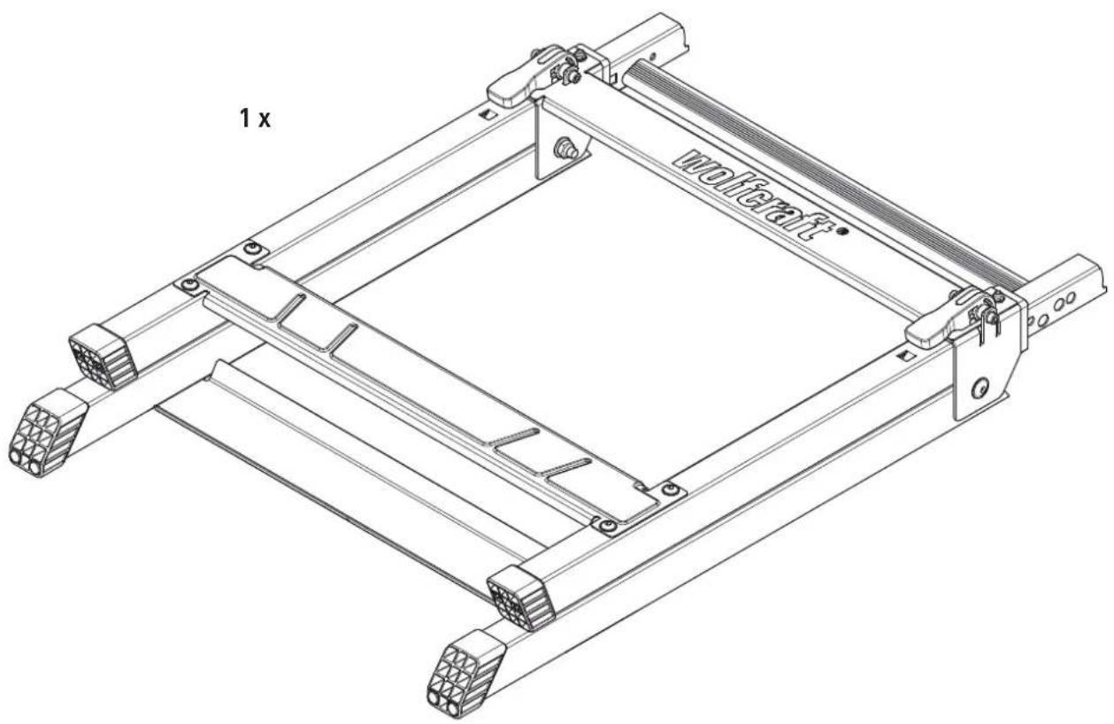
1

119936902
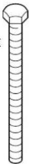
4×4×
M 6 x 80
DIN 931
natural_image
Isometric line drawing of a mechanical component with internal grid structure (no text or symbols)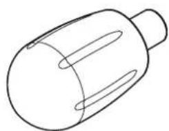
natural_image
Simple line drawing of a cylindrical object with internal oval cutouts (no text or symbols)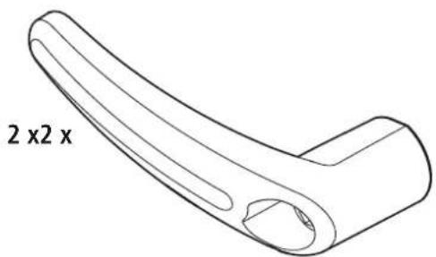
DE Montageanleitung
EN Assembly instructions
EN Height adjustment
FR Hauteur réglable
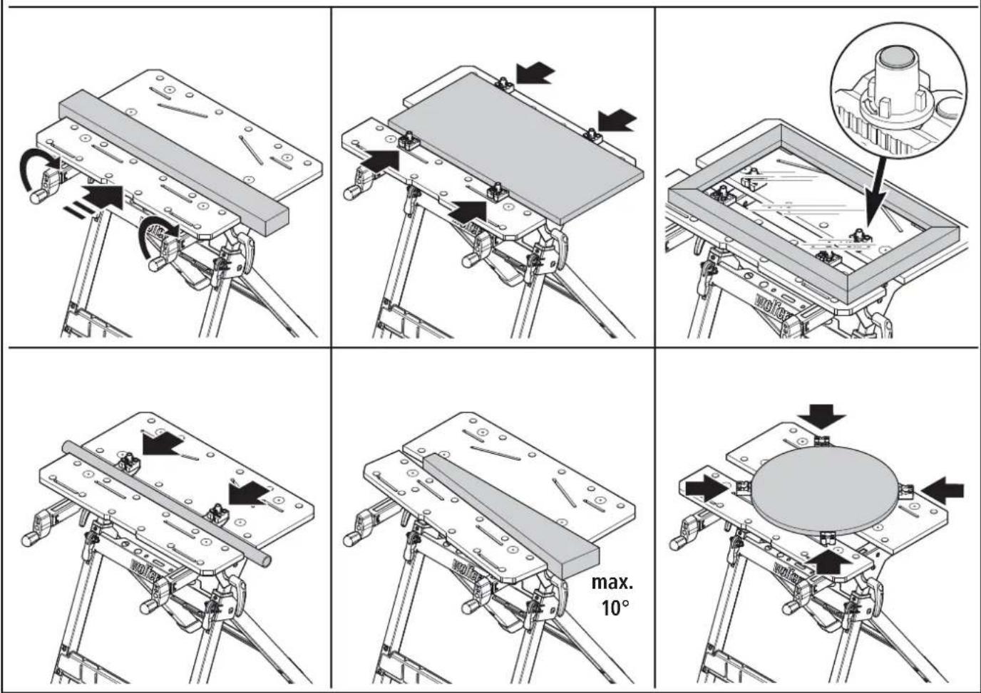
EN Adjusting the worktop
EN Clamping the workpiece
flowchart
graph TD
    A["1. Valve with no weight, 125 kg scale"] --> B["2. Valve with force arrows indicating motion"]
    B --> C["1. Head with no weight, 125 kg scale"]
    C --> D["2. Head with force arrows indicating motion"]
DE Gerätemontage
EN Device assembly
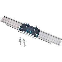
EN Accessories available separately
natural_image
Technical line drawing of a mechanical clamp or fixture assembly (no text or symbols visible)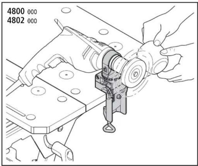
natural_image
Technical line drawing of a mechanical clamp assembly with mounting base (no text or symbols)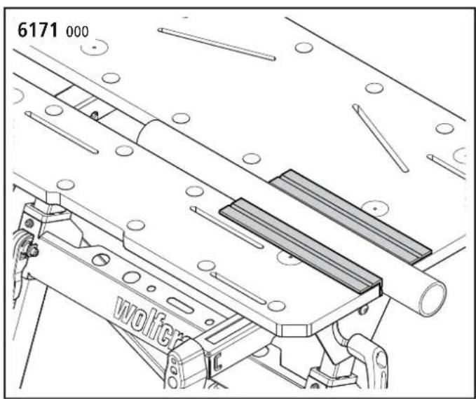
natural_image
Technical line drawing of a mechanical assembly with rollers and a labeled component 'wolfer' (no readable text or symbols beyond label)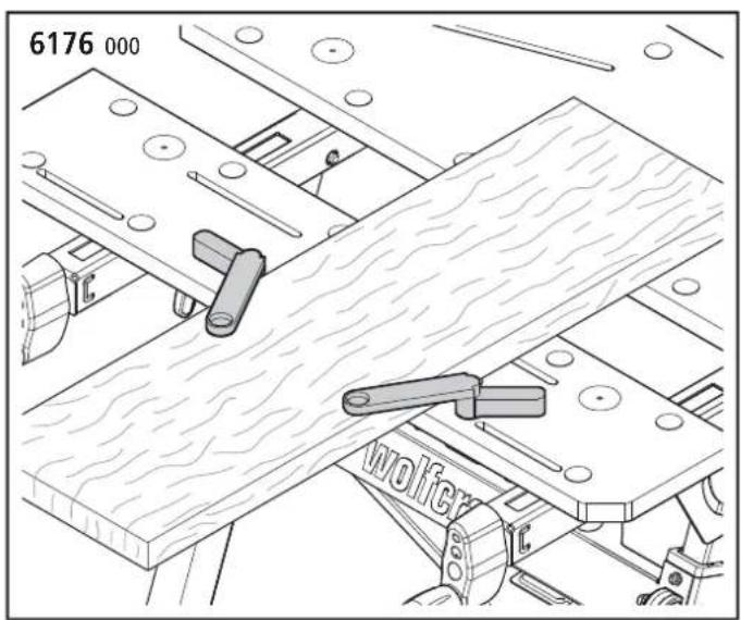
natural_image
Technical line drawing of a wooden plank assembly with levers and bolts (no text or symbols)DE Ersatzteilliste
EN Spare parts list
DE Zubehörbeutel
EN Accessory bag
natural_image
Isometric line drawing of a mechanical component with internal grid structure (no text or symbols)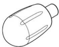
natural_image
Simple line drawing of a cylindrical object with internal oval cutouts (no text or symbols)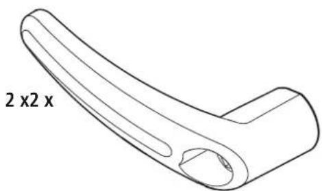
natural_image
Line drawing of a curved mechanical component with two side groups labeled '2 x 2 x' (no other text or symbols)ALLGEMEINE INFORMATIONEN
EINLEITUNG
These operating instructions describe the MASTER 750 L8GO Clamping and Working Table (hereafter also referred to as "Product"). Keep the operating instructions in a safe place for future reference.
The purpose of the figures in this operating manual is to help you better understand the topics and step sequences. The representations in the figures are examples and may deviate slightly from the actual appearance of your product.
SYMBOLS AND MEANINGS

WARNING
WARNING
...means that there is risk of severe to life-threatening injury.

CAUTION
CAUTION
...means that there is risk of minor to moderate injury.
NOTICE
NOTICE
...indicates important information (e.g. risk of property damage), but not hazards.

Info!
This symbol indicates information that helps you to quickly and safely perform your tasks.

Warning of a danger
This symbol indicates a general hazard that, if not avoided, could result in injury.

Risk of crush injuries to hands
This symbol indicates hazardous situations that could result in hand injuries.

Observe instructions!
This symbol indicates that the operating instructions have to be followed.

Wear safety goggles!
This symbol indicates that you have to wear safety goggles.

Wear ear protection!
This symbol indicates that you have to wear ear protection.

Wear protective gloves!
This symbol indicates that you have to wear protective gloves.

Wear protective mask!
This symbol indicates that you have to wear a protective mask.

Unplug from the mains!
This symbol indicates that you have to unplug from the mains.
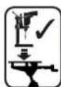
Suitable for use with drill stands
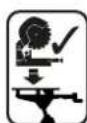
Suitable for use with mitre saws

Do not apply weight unevenly!

Maximum load: 125 kg

Do not use as a seat, ladder or support.

Do not stand on the working table.
SAFETY
GENERAL SAFETY INFORMATION

WARNING
Disregarding the safety information and instructions leads to risk of injury!
Failure to comply with safety information and instructions can lead to electric shock, fire and/or serious injury.
a) By following the safety information and instructions provided in these operating instructions, personal injury and property damage can be prevented when working at or with the product.
b) Before starting any work, read the operating instructions, in particular the Safety chapter and the respective safety instructions. It is important to understand the information that has been read.
Always obey the following safety instructions:
- Assemble the working table correctly and check that all the handle screws and screw joints are tight before beginning work. Correct assembly ensures that the table does not fold up and the table top does not tilt unintentionally.
- Never use your working table improperly or for an unintended purpose! Any use other than the intended use can lead to hazardous situations.
- Keep your work area clean and remove all unnecessary items from the working table. Clutter on the work area can cause accidents.
- Make sure that your hands do not get caught in the folding, sliding or tilting parts of the working table. Risk of injury.
- Never work with a defective working table!
- Clamp the workpiece to be processed firmly! It is safer to hold a workpiece in place with clamping jaws or other clamping devices than with your hand.
- Make sure that all screws and handle screws are tight during transport.
- Place the working table on a firm, level and horizontal surface. If the working table can slip or wobble, the workpiece or power tool cannot be controlled evenly and safely.
- Make sure that both eccentric levers are always tightened so that the height of the table cannot change.
— Set up the working table correctly before mounting the power tool. - Fasten the power tool securely on the working table before using it. If the power tool slips on the working table, this can lead to loss of control.
- Make sure that the power tool is mounted centrally on the working table. If the power tool is not centred on the working table, this can mean the centre of gravity of the power tool does not align with the centre of gravity of the working table, so that the table can tip over.
- Make sure that long workpieces do bring the working table out of balance. Long workpieces must be supported at the free end.
- Wear suitable personal protective equipment: ear protection, safety goggles, dust mask if the work generates dust, protective gloves when working with rough materials and when changing tools.
- Do not store the working table outdoors or in a damp environment. There is a risk of corrosion and the worktop may warp.
- Make sure to follow the instructions and safety information supplied in the original operating manual for the power tool used. The machines used must comply with DIN EN 62841-1 or DIN EN 60745-1. Devices manufactured after 1995 must bear a CE mark.
- Keep your work area clean and well lit. Untidy or dark work areas can lead to accidents.
- Keep children and other persons at a safe distance when using the working table. If you are distracted, you may lose control of the device.
- Remove the adjusting tools or spanners before switching on the power tool. A tool or spanner left in a rotating part of the device can cause injury.
- Wear suitable clothing. Never wear loose clothing or jewellery. Keep hair, clothing and gloves away from moving parts. Loose clothing, jewellery or long hair can get caught in moving parts.
— Before starting work, check that the devices and tools are operational. Never work with damaged or blunt tools.
- Disconnect the plug from the electric socket and/or remove the battery from the power tool before adjusting the tool or changing accessories. Accidents may occur if the power tool is started unintentionally.
- Avoid overloading the working table and never use it as a seat, ladder or support. Placing excess weight on the working table or standing on it can cause the centre of gravity of the table to shift, so that it tips over.
- Never reach into the saw area to remove loose fragments, chips or similar materials from the area around the moving saw blade by hand! There is risk of your hand or arm getting caught in the rotating tool, which could cause severe injury.
- Before each sawing operation, make sure that there are no objects on the worktop.
- Do not stop the saw blade by applying lateral pressure after switching off the drive. This poses risk of damaging the saw blade or causing kickback.
- Only use tools for their actual intended purpose. Using power tools for applications other than the intended use can result in hazardous situations.
- Only use saw blades that are in perfect condition. Saw blades that are blunt, defective or do not fit correctly can cause kickback or loss of control.
– Only use genuine wolfcraft spare parts.
- Additionally support protruding or large workpieces, to prevent risk of tilting, and make sure that lateral clamping and machining of laterally clamped workpieces does not result in the table becoming unbalanced. When workpieces protrude beyond the table, the centre of gravity can shift outward, which can cause damage to the workpiece or risk of injury from tilting.
- If you use mitre saws or drill stands on the working table, they have to be firmly bolted to the table.
- Mount mitre saws or drill stands on the table only when the worktop is in the 90^ position.
- Do not use the working table with a clamped circular handsaw or in combination with a cutting stand.
- Make sure that you do not apply excessive clamping pressure when fastening fragile materials. There is risk of splintering!
- Remove all tools from the tool holders of the table before folding up the table, so that there is no risk of the contained tools falling or damaging the table.
— Take care not to pinch your hands when folding and unfolding the table.
INTENDED USE
The MASTER 750 ^ERGO can be used for the following purposes:
- As a clamping and working table for machining workpieces (e.g. drilling, sanding, etc.).
- For clamping workpieces between the table tops
- For clamping larger workpieces by means of plastic clamping jaws that have been additionally mounted to the working table.
- For mounting mitre saws and drill stands. For this, the supplied fastening bolts have to be used. Observe the manufacturer's safety instructions for the machines used, as well as the safety instructions for the working table.
FORESEEABLE MISUSE
Any use other than that described in the chapter on intended use is considered reasonably foreseeable misuse, e.g.:
— Not observing the safety instructions for this product or the mounted tool.
— Mounting machines that apply lateral pressure to the working table.
- Using the table as work platform or seat.
- Applying a load of more than 125 kg.
- Clamping long workpieces with one end protruding without suitable support, causing the centre of gravity to shift outward, which could result in the working table tilting over.
The manufacturer does not accept any liability for property damage or personal injury resulting from reasonably foreseeable misuse or from failure to observe the operating instructions.
PRODUCT OVERVIEW
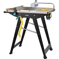
PRODUCT DESCRIPTION
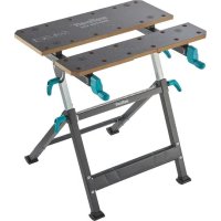
The MASTER 750 ^LPGD is a height-adjustable clamping and working table. It is suitable for use as a working table for machining workpieces (e.g. drilling, sanding, etc.). With the working table, a variety of workpieces can be clamped between the table tops. The additional plastic clamping jaws permit larger workpieces to be clamped. The height of the working table can be adjusted between 725 and 950 mm, in six steps. The tabletop can be variably inclined between 0° and max. 60°. The max. load is 125 kg. Mitre saws or drill stands may be mounted on the working table using the fastening screws supplied; the technical data has to be observed.
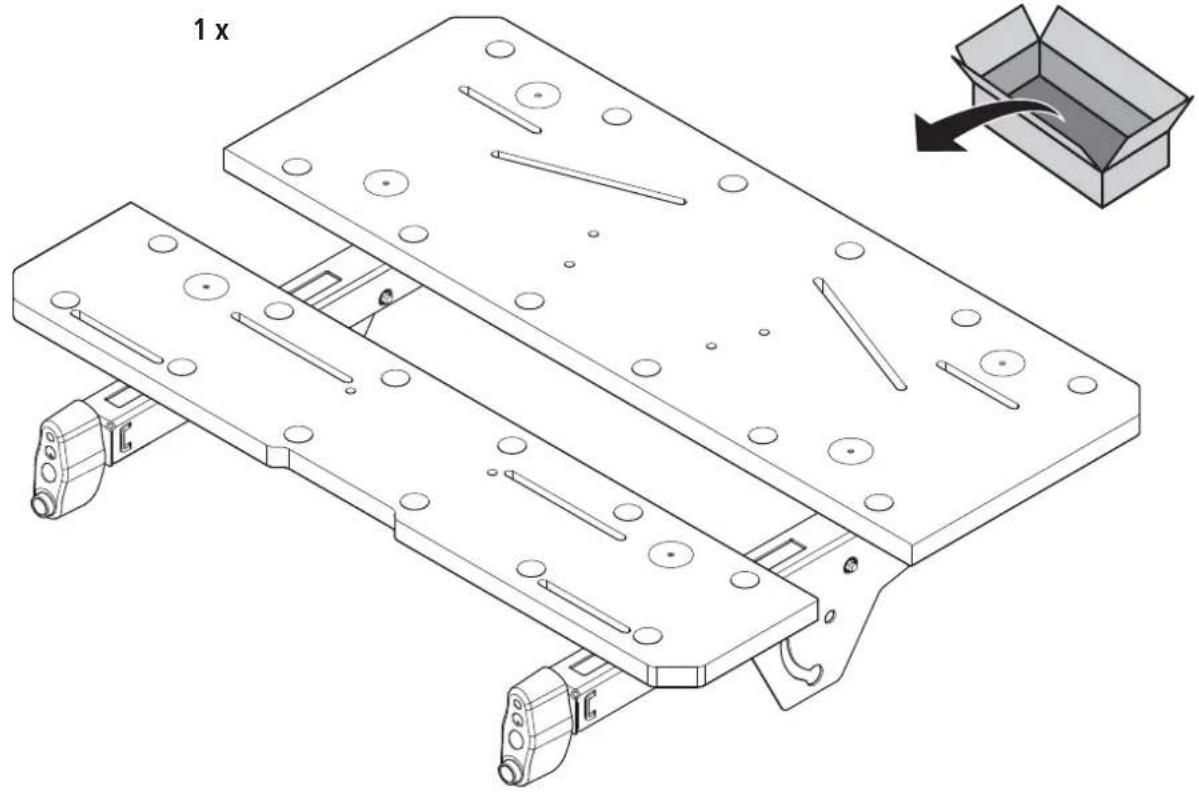
SCOPE OF DELIVERY
Take the MASTER 750 ^ERGO out of the cardboard box and check that the contents are complete and all illustrated parts are included (Fig. 1).
TECHNICAL DATA
| Dimensions when set up for use (width x depth x height): | 680 x 585 x 725 - 950 mm |
| Dimensions when folded up (width x depth x height): | 680 x 190 x 970 mm |
| Tilt of table surface: 0° - 60° | |
| Clamping area between table tops: 130 mm | |
| Clamping area between plastic clamping jaws: | 425 mm |
| Clamping area for long objects that are standing on the floor (Fig. 9.2): | 50 - 110 mm |
| Bore diameter of clamping holes: 20.2 mm | |
| Maximum load: 125 kg | |
| Weight: 13.2 kg | |
ASSEMBLY
ASSEMBLY TOOL
The following assembly tools are required (not included in scope of supply):

Allen key:
A/F 4
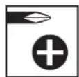
Screwdriver:
PZ 3

Spanner:
A/F 10
ASSEMBLY

CAUTION
Risk of crush injuries to fingers and hands during assembly
When moving parts are being mounted, there is risk of shear movements, especially if the handle screws, which have a securing function, have not been mounted yet.
Pay attention to your hands and the selected holding positions during assembly work. If necessary, ask a second person to assist you.
Place the lower section of the table on a flat, clean surface. Make sure that both eccentric levers are pressed against the table legs, so that the telescopic adjustment is fixed (Fig. 2.1).
Fold out the footpiece to the limit stop (Fig. 2.2) and place the worktop onto the lower section. Make sure that the two pins on the right and left crossbars engage in the slot on the telescopic adjustments of the base frame (Fig. 2.3). Tighten the screw connections consisting of nut, washer, bearing bush and screw only to the
point where the worktop can still be swivelled (Fig. 2.4). Then mount the handle screws, washers and screws. Make sure that the embossing on the washer is aligned correctly. After assembly, tighten both handle screws (Fig. 2.5).
Finally, use the appropriate screws and washers to install the handles on the two hand cranks. (Fig. 2.6).
OPERATION
FOLDING UP THE TABLE
Fold up the table as follows:
Check the height adjustment and set it to the lowest position (if in another position). Also check whether both eccentric levers have been pressed down, so that the height adjustment is fixed. First close the clamping jaws of the working table (Fig. 3.1). At the left and right, release the two handle screws at the crossbar and swivel the worktop until it reaches the limit stop (Fig. 3.2 - Fig. 3.3). To fix the worktop in place, tighten the two handle screws again. Now slightly tilt the table onto the rear feet and fold in the front footpiece until it reaches the stop (Fig. 3.4). The table can be carried with one hand holding it at the cutout in the table top (Fig. 3.5). For storage, lean the table against a wall at a slight angle to prevent it from falling over (Fig. 3.6).
FOLDING OUT THE TABLE

CAUTION
Risk of injury from uncontrolled movements of the working table
If the feet of the working table are not folded out completely, there is risk of uncontrolled table movements.
Before starting work, make sure that the feet have been folded out fully and the working table is standing securely.
Unfold the table as follows:
Make sure that both eccentric levers have been pressed down tightly, so that the height adjustment is fixed, and that both handle screws for swivelling the worktop have been tightened (Fig. 4.1). Fold out the footpiece to the limit stop (Fig. 4.2). At the left and right, release the two handle screws at the crossbar and swivel the tabletop to the horizontal position (Fig. 4.3). Fix the worktop in place by tightening the two handle screws again. Subsequently make sure that the table is standing securely (Fig. 4.4).
TABLE HEIGHT ADJUSTMENT

CAUTION
Risk of injury from uncontrolled movements of the working table
If the eccentric levers at the working table are not pressed tightly against the table legs, there is risk of the worktop sinking down during work.
Before starting any work and after each adjustment of the work height, make sure that the two eccentric levers are pressed tightly against the table legs, so that the worktop cannot tilt and is securely fixed in place.
You can now adjust the working height. There are six possible positions, from 725 to 950 mm. Proceed as follows:
Make sure that both handle screws have been firmly tightened. Release both eccentric levers in the direction of the arrow (Fig. 5.1). Slightly pull the worktop towards you until it is released from the locking positions. The worktop can now be adjusted to the desired height (Fig. 5.2 - Fig. 5.3). Make sure that the worktop has engaged in one of the four locking positions again and close both eccentric levers by pressing them against the table legs to fixate the tabletop (Fig. 5.4 - Fig. 5.5).
TILTING THE TABLE TOP

CAUTION
Risk of injury from falling workpieces or tools
Any mounted devices, tools and workpieces must be removed from the working table before tilting the table top.

CAUTION
Risk of injury from uncontrolled movements of the working table
If the handle screws at the working table are not tightly closed, there is risk of the worktop folding when work is performed on it.
Before starting any work and after each adjustment of the work angle, make sure that both handle screws have been tightened, so that the worktop cannot tilt and is securely fixed in place.
The table top can be tilted at an angle of between 0^ and 60^ . To do so, proceed as follows:
Make sure that both eccentric levers for the height adjustment have been firmly tightened, so that the height of the table cannot change. At the left and right, release the two handle screws at the crossbar and swivel the worktop to the desired position (Fig. 6.1 - Fig. 6.3). To fix the worktop in place, tighten the two handle screws again (Fig. 6.2).
OPERATING FUNCTIONS

CAUTION
Risk of injury from uncontrolled movements of the working table
If the two eccentric levers are not pressing tightly against the table legs or the handle screws of the angle adjustment are loose, there is risk of uncontrolled table movements.
Before starting work, make sure that the handle screws are tight and the two eccentric levers are pressed tightly against the table legs, so that the worktop cannot tilt and is securely fixed.
QUICK ADJUSTER OF THE FRONT TABLE TOP
NOTICE
If the spindles are tensioned, release the tension before using the quick adjuster.
Pull both levers of the quick adjuster outward and hold them in the pulled-out position. Position the front table top by moving it to the desired position. Release the two levers of the quick adjuster and clamp the workpiece with the two hand cranks (Fig. 7.1).

CAUTION
Risk of injury from workpiece that becomes loose
Shifting the table top by means of the quick adjuster does not exert any clamping force on the workpiece yet.
Always tighten both hand cranks to clamp the workpiece in place.
CLAMPING WORKPIECES
The plastic clamping jaws included in the scope of delivery offer a wide range of clamping and support options for workpieces. The four additional support tips are inserted into the clamping jaws as shown and secured by twisting them to the side. (Fig. 7.2).
To clamp a workpiece, insert the clamping jaws (if needed) into the table tops of the working table and position the workpiece between the table tops or clamping jaws. Turn the two hand cranks clockwise to clamp a workpiece. To release the workpiece, turn the two hand cranks anti-clockwise.
DEVICE ASSEMBLY

CAUTION
Risk of injury from a falling device
Before devices are mounted, the table top must be in the horizontal position and firmly fixed with both handle screws. It is not permitted to mount devices if the table top is set at an angle.

WARNING
Risk of injury from improper mounting of a device
Before starting any work, always make sure that all four screw joints between the device and table have been tightened properly.
Mitre saws or drill stands may be mounted on the table using the fastening bolts supplied in the scope of delivery.
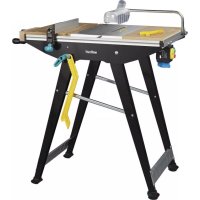
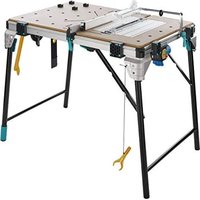
MOUNTING A MITRE SAW
Place the mitre saw in the centre of the table with the mounting bores aligned with the slots of the two table tops. The front table top can be extended or retracted until the slots are positioned beneath the front mounting bores. Now fasten the mitre saw by inserting the four screws and the four small washers through the mounting bores and table tops from above. With the large washers and nuts, firmly tighten the screws from below (Fig. 8.1). Subsequently check that the mitre saw is mounted in the centre of the table, so that the centre of gravity of the saw is in the middle and the table cannot tip over.

Alternative mounting method
When the slotted holes above the spindles are used, the screws have to be inserted from below (Fig. 8.2).
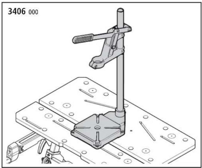
MOUNTING THE WOLFCRAFT 3406 ^000 OR 5027 ^000 DRILL STAND
Place the drill stand in the centre of the table with the mounting bores aligned with the slots of the two table tops. The front table top can be extended or retracted until the slots match the front mounting bores. Insert the four screws and four large washers through the mounting bores from above and tighten them with the small washers and nuts underneath the tabletop (Fig. 8.3).
MAINTENANCE AND CLEANING
- After any work, always clean the clamping and working table using a dry cloth.
— Do not use aggressive and/or abrasive cleaning agents or solvents.
DISASSEMBLY AND DISPOSAL
Dispose of the packaging materials in an environmentally friendly manner. In the event of disposing of the MASTER 750 ERGO, observe local disposal regulations.
WARRANTY CONDITIONS
Dear DIY enthusiast, you have purchased a high-quality wolfcraft® product which we know you will enjoy using. wolfcraft® products are built to high technical standards and undergo intensive development and testing before leaving the factory. Constant checks and regular tests during their production ensure a high standard of quality. Sound technical developments and reliable quality assurance give you the certainty that you have made the right purchase decision. For this wolfcraft product, we grant you a 10 year warranty from the date of purchase, provided it is used exclusively for DIY purposes. This warranty only covers damage to the object of purchase itself and only such damage that is attributable to material or manufacturing defects. This warranty does not cover defects or damage attributable to improper operation or inadequate maintenance of the appliance. Moreover, the warranty does not include the effects of normal wear, or defects or damage known to the customer upon conclusion of the purchase contract. Warranty claims can only be asserted upon submission of the invoice/proof of purchase. The warranty granted by wolfcraft does not restrict your legal rights as a consumer (supplementary performance, rescission or reduction, compensation for damages or expenses).
Address warranty claims to:
wolfcraft GmbH
Wolffstraße 1
56746 Kempenich
Germany
INFORMATIONS GÉNÉRALES
INTRODUCTION
CONDITIONS DE GARANTIE
SYMBOLIT JA NIIDEN MERKITYS

VAROITUS
VAROITUS
DEMONTÁŽ A LIKVIDACE
AZ ASZTALLAP DÖNTÉSE
VIGYÁZAT
customerservice@wolfcraft.com
(correspondence in English)
AT TR BA
wolfcraft GmbH
Hauffgasse 3-5
A-1110 Wien
Tel.: +43 (1) 7 48 08 08-0
Fax: +43 (1) 7 48 08 08-11
kundendienst@woaut.wolfcraft.com
FR BE LU
wolfcraft s.a.r.l.
1 Rue d'Aurion
F-93110 Rosny-sous-Bois
68, Kliment Ohridski Blvd.
BG-1756 Sofia
Telefon: + 359 70045454
Telefax: +359 4392112
info@tashev-galving.com
GR CY
AN Mavrofidopoulos S.A.
Technical & Commercial Company
Salaminos 1 & Mavromihali Str.
GR-185 45 Piraeus
Telefon: + 30 21 0413 6155
Telefax: + 30 21 0413 7692
info@mavrofidopoulos.gr
HR
Manal d.o.o.
Velimira Skorpika 1 a
HR-10090 Zagreb
Telefon: + 385-1-3466400
Telefax: + 385-1-3466412
manal@manal.hr
RO MD
PARTENER SRL
Calea Moinesti, nr.34,
Pavilion Administrativ, et. 3
RO-600281 Bacau
Tel.: + 40 234 588 750
Fax: +40 234 510 081
vanzari@partner.ro
RS ME
Mi-lumen d.o.o.
Tanaska Rajića 10b
RS-36212 Kraljevo-Ratina
Tel. + 381 36 331 081
info@mi-lumen.co.rs
NMK
FAMOD
Bul. Vidoe Smilevski 5
NMK-1000 Skopje
Telefon: + 389 2 2431100
Telefax: + 389 2 2431105
famod@t-home.mk
EE
AS Tooma Tööriist
Männiku tee 107
EE-11215 Tallinn
Telefon: + 372 6 586229
Fax: +372 6 546725
info@toomatool.ee
BY
UP "18"
Kutuzova 15
BY-220049 Minsk
Telefon: + 375 17 3517317
Fax + 375 17 3579676
info@up18.by
RU
Centro Instrumentalnoj Torgovli
Molodogvardejskaya UI 61
RU-121351 Moskau
Tel.: + 7 495 730 80 70
ci@centro-i.ru
MT
ANASTASI & BRIFFA LTD
Quarries Square Street
MT-1752 St. Venera
Tel.: + 356 99 429402
nastas@onvol.net