
PD 2G 18.0EC - Drill Flex - Free user manual and instructions
Find the device manual for free PD 2G 18.0EC Flex in PDF.
| Product Type | Cordless Hammer Drill |
| Brand | Flex |
| Model | PD 2G 18.0EC |
| Battery Voltage | 18 V |
| Battery Type | Lithium-ion (2.5 Ah / 5.0 Ah) |
| No-load speed (speed 1 / 2) | 0-600 min⁻¹ / 0-2300 min⁻¹ |
| Hammer rate (speed 1 / 2) | 0-9600 min⁻¹ / 0-37000 min⁻¹ |
| Maximum torque (hard screwing) | 90 Nm |
| Number of torque positions | 24 + drilling |
| Max drilling diameter (wood / steel / masonry) | 60 mm / 13 mm / 16 mm |
| Chuck capacity | 1.5-13 mm |
| Weight (without battery) | 1.6 kg |
| Work light | LED (turns off after approx. 10 s) |
| Motor brake | Yes |
| Battery charge indicator | LED display on battery |
| Battery protection | Against heat, fire, water and short circuits |
| Compatible charger | CA 10.8/18.0 |
| Maintenance | Clean ventilation slots with dry compressed air |
| Repairs | Flex authorized service center |
| Compliance | CE, EN 62841 |
Frequently Asked Questions - PD 2G 18.0EC Flex
User questions about PD 2G 18.0EC Flex
0 question about this device. Answer the ones you know or ask your own.
Ask a new question about this device
Download the instructions for your Drill in PDF format for free! Find your manual PD 2G 18.0EC - Flex and take your electronic device back in hand. On this page are published all the documents necessary for the use of your device. PD 2G 18.0EC by Flex.
USER MANUAL PD 2G 18.0EC Flex
- AP 10.8 (2,5 Ah),
- AP 18.0 (2,5 Ah),
- AP 10.8 (5,0 Ah),
- AP 18.0 (5,0 Ah).
Klaus Peter Weinper
Head of Quality
Department (QD)
18.12.2017
Symbols used in this manual 17
Symbols on the power tool 17
Important safety information 17
Noise and vibration 19
Technical data 20
Overview 21
Instructions for use 22
Maintenance and care 28
Transport 29
conformity 29
Disposal information 29
Exemption from liability 29
Symbols used in this manual
WARNING!
Denotes impending danger. Non-observance of this warning may result in death or extremely severe injuries.
CAUTION!
Denotes a potentially dangerous situation. Non-observation of this warning may result in injury or damage to property.
i NOTE
Denotes application tips and important information.
Symbols on the power tool

Before switching on the power tool for the first time, read the operating manual.
Wear protective goggles.

Short-circuit-proof safety transformer.
Protect the battery against heat, including prolonged sunshine, and fire. Explosion hazard!.
Do not throw the battery into a fire. Explosion hazard!
The tool is only suitable for use indoors. Do not expose the tool to rain. Store power tools and batteries in dry rooms.
Disposal information (see page 29).
Important safety information
WARNING!
Read all safety warnings, instructions, illustrations and specifications provided with this power tool. Failure to follow all instructions listed below may result in electric shock, fire and/or serious injury. Save all warnings and instructions for future reference.
Before using the power tool, please read the following and act accordingly:
- these operating instructions,
- the "General safety instructions" on the handling of power tools in the enclosed booklet (leaflet no.: 315.915),
- the currently valid site rules and the regulations for the prevention of accidents.
This power tool is state of the art and has been constructed in accordance with the acknowledged safety regulations.
Nevertheless, when in use, the power tool may be a danger to life and limb of the user or a third party, or the power tool or other property may be damaged.
The power tool may be operated only if it is
- for its intended use,
- in perfect working order.
Faults which compromise safety must be repaired immediately.
Intended use
The DD 2G 18.0-EC cordless drill driver is intended
- for commercial use in industry and trade,
- for inserting and releasing screws,
- for drilling in wood, metal, ceramic and plastic.
The PD 2G 18.0-EC cordless percussion drill is intended
- for commercial use in industry and trade,
- for inserting and releasing screws,
- for drilling in wood, metal, ceramic and plastic,
- for impact drilling in brick, masonry and stone.
The IW 1/2" 18.0-EC / ID 1/4" 18.0-EC cordless impact driver is intended
- for commercial use in industry and trade,
- for tightening and releasing nuts and screws in the specified dimensions.
Safety instructions for drills and drivers
Hold the power tool by the insulated gripping surfaces when performing an operation where the cutting accessory or the screw may contact hidden wiring or its own power cord.
The screw contacting a "live" wire may make exposed metal parts of the power tool "live" and cause an electric shock.
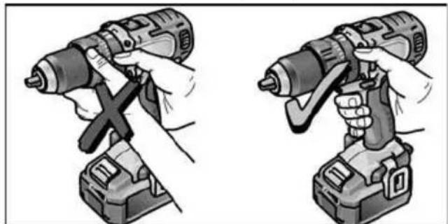
Use auxiliary handles if these are supplied with the power tool. The loss of control may result in injuries.
Use suitable detectors to detect concealed power supply cables or consult your local supply company. Contact with electric cables may result in a fire and/or electric shock. A damaged gas pipe may cause an explosion. Cutting into a water pipe will cause damage to property.
- Switch off the power tool immediately when the cutting accessory jams. Be prepared for high reaction torques which cause kickback. The cutting accessory jams when:
- the power tool is overloaded or
-
it snags in the workpiece to be machined.
-
Maintain a firm grip on the power tool. High reaction torques can occur briefly when screws are tightened and released.
-
Secure the workpiece. A workpiece is held more securely in a clamping device or vice than by hand.
Wait until the power tool has come to a stop before putting it down. The cutting accessory may snag, causing the operator to lose control of the power tool.
Use only original batteries with the voltage indicated on the type plate of your power tool. The use of other batteries, e.g. imitations, reconditioned batteries or other makes, increases the risk of injury and damage to property by exploding batteries.
Additional safety instruction for percussion drill (PD ...)
Wear ear defenders when impact drilling. The effect of noise may result in loss of hearing.
Safety instructions for handling batteries
- Do not open the battery. Short-circuiting hazard!
- Protect the battery against heat, including prolonged sunshine, fire, water and moisture. Explosion hazard!
A damaged or incorrectly used battery may result in the emission of fumes.
Ensure a supply of fresh air and consult a doctor in the event of any physical complications. The fumes may irritate the respiratory tracts.
Liquid may leak out of the battery if the battery is incorrectly used. Avoid contact with such liquid. If contact accidentally occurs, rinse with water. If liquid contacts eyes, seek medical attention.
Liquid discharged from the battery may cause irritation or burns.
Recharge batteries only with chargers recommended by the manufacturer.
A charger that is suitable for one type of battery may create a fire hazard when used with another battery.
The battery may be damaged by pointed objects such as e.g. nails or screwdrivers or by external application of force. This may give rise to an internal short circuit, causing the battery to burn, smoke, explode or overheat.
Charger
Always check whether the mains voltage matches the voltage indicated on the type plate of the charger.
The charger plug must fit in the power socket. Never modify the plug in any way. Do not use any adapter plugs together with earthed (grounded) power tools. Unmodified plugs and matching power sockets will reduce the risk of electric shock.
Only use the charger in dry rooms and avoid all contact with moisture and rain. The ingress of water into the charger increases the risk of electric shock.
- Never use the charger if cables, plugs or the device itself are damaged as a result of external influence. Take the charger to the nearest authorised repair shop.
Under no circumstances open the charger. In the event of a fault, take it to an authorised repair shop.
- Do not place any objects on the charger and do not place the charger on soft surfaces. Fire hazard!
Special safety instructions
Before carrying out any work on the power tool, move the direction preselector switch (2) to the middle position.
Operate the direction preselector switch (2) or torque setting turning dial (5) only when the tool is stopped.
- Identify the power tool with stickers only. Do not drill any holes into the housing.
Noise and vibration

NOTE
The noise and vibration values have been determined in accordance with EN 62841. The values are set out in the "Technical data" table.

WARNING!
The indicated measurements refer to new power tools. Daily use causes the noise and vibration values to change.

NOTE
The vibration emission level given in this information sheet has been measured in accordance with a measurement method standardised in EN 62841 and may be used to compare one tool with another. It may be used for a preliminary assessment of exposure. The specified vibration emission level represents the main applications of the tool.
However, if the tool is used for different applications, with different cutting accessories or poorly maintained, the vibration emission level may differ.
This may significantly increase the exposure level over the total working period. To make an accurate estimation of the vibration exposure level, it is also necessary to take into account the times when the tool is switched off or running but not actually in use. This may significantly decrease the exposure level over the total working period. Identify additional safety measures to protect the operator from the effects of vibration such as: maintain the tool and the cutting accessories, keep the hands warm, organisation of work patterns.

CAUTION!
Wear ear defenders at a sound pressure above 85 dB(A).
Technical data
| Tool DD 2G | 18.0-EC | PD 2G 18.0-EC | IW 1/2" 18.0-EC | ID 1/4" 18.0-EC | |
| Type | Drill driver | Impact drill driver | Impact driver | Impact driver | |
| Battery AP 18.0/2.5 | AP 18.0/5.0 | ||||
| Charging time (depending on state of charge) | |||||
| - AP 18.0/2.5 | min | 0-40 | |||
| - AP 18.0/5.0 | min | 0-45 | |||
| Torque, max. | |||||
| - Soft screwdriving case | Nm | 56 | 56 | - | - |
| - Hard screwdriving case | Nm | 90 | 90 | 250 | 225 |
| Torque settings 20 24 - | |||||
| Idling speed | |||||
| - Stage 1 | r.p.m. | 0...600 | 0...600 | 1500 | 1500 |
| - Stage 2 | r.p.m. | 0...2300 | 0...2300 | 2000 | 2000 |
| - Stage 3 | r.p.m. | - | - | 2500 | 2500 |
| Schlagzahl | |||||
| - Stage 1 | r.p.m. | - | 0...9600 | 1300 | 1300 |
| - Stage 2 | r.p.m. | - | 0...37000 | 2800 | 2800 |
| - Stage 3 | r.p.m. | - | - | 3300 | 3300 |
| Chuck mm 1.5-13 - | |||||
| Max. drill diameter | |||||
| - in wood | mm | 60 | 60 | - | - |
| - in steel | mm | 13 | 13 | - | - |
| - in masonry | mm | 16 | 16 | - | - |
| Weight according to "EPTA Procedure 01/2003" (without battery) | kg 1.5 | 1.6 | 1.1 1.1 | ||
| Weight battery 2.5 Ah | kg | 0.4 | |||
| 5.0 Ah | kg | 0.7 | |||
| A-weighted sound pressure level | |||||
| Sound pressure level LpA | dB(A) 78* | 78* | 95** | 91*** | |
| Sound power level LWA | dB(A) 89* | 89* / 106** | 102*** | 102*** | |
| Uncertainty K | db 3.0 | ||||
| Overall vibration values (vector sum of three directions) | |||||
| Vibration emission value ah when .... | |||||
| - drilling in metal | m/s² | <2.5 | <2.5 | - | - |
| - impact drilling in concrete | m/s² | - | 15.5 | - | - |
| - screwing | m/s² | <2.5 | <2.5 | 18.5*** | 18.5*** |
| Uncertainty K | m/s² | 1.5 | |||
- drilling in metal / ** impact drilling in concrete / *** impact driving
Overview
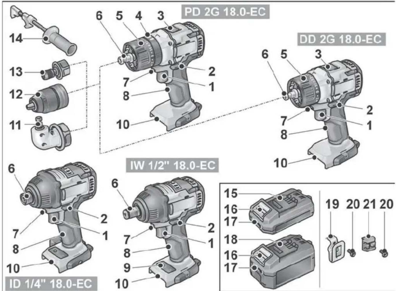
Different electric power tools are described in these instructions. The illustrated electric power tool may differ in detail from the one which you purchased.
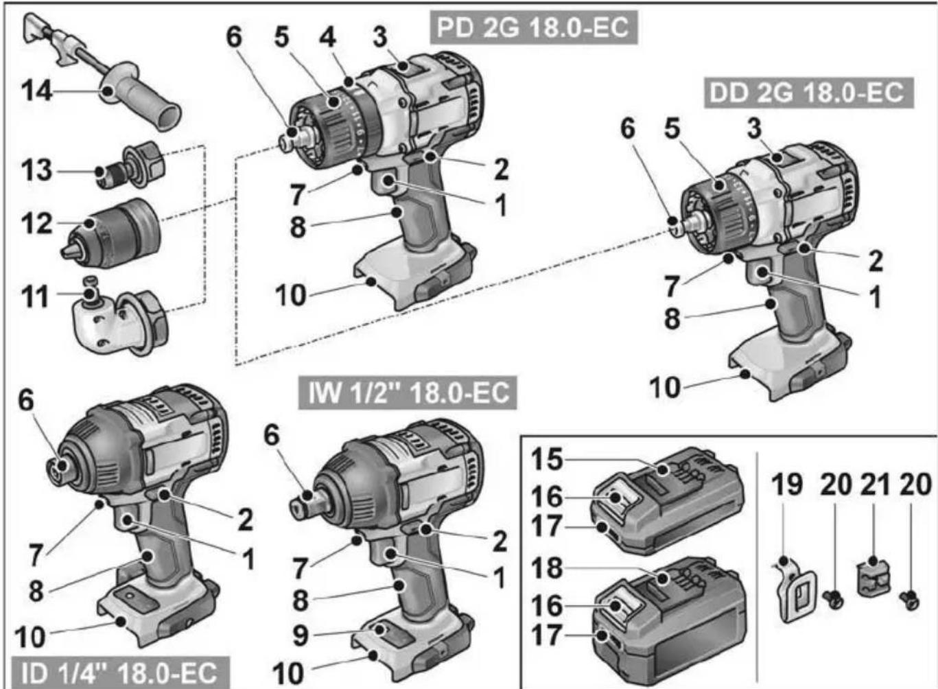
For switching on and off and for accelerating up to maximum rotational speed
1 Trigger switch
2 Direction preselector switch
3 Speed selector switch
4 Turning dial for operating mode (PD... only)
5 Turning dial for torque setting
6 Tool holder
7 Workplace lighting
8 Handle
9 Speed control panel
10 Insertion slot for battery
11 Angle attachment with release ring
12 Exchange chuck with release ring
13 Bit holder attachment with release ring
14 Auxiliary handle
15 Li-ion battery (2.5 Ah)
16 Release button for battery
17 State of charge indicator
18 Li-ion battery (5.0 Ah)
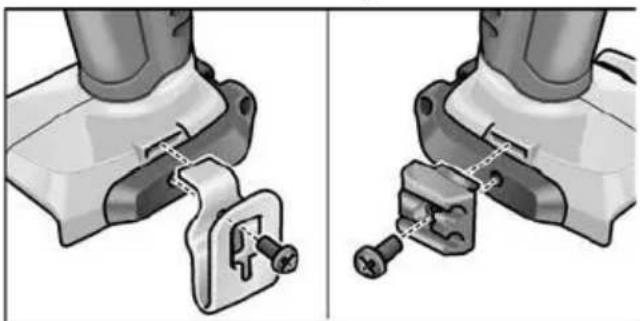
19 Belt clip
20 Fastening screw
21 Bit bracket
Instructions for use
Before initial operation
Unpack the power tool and accessories and check that no parts are missing or damaged.
- Attach the belt clip and bit holder with the enclosed fastening screw.
i NOTE
The batteries are not fully charged on delivery. Prior to initial operation, charge the batteries fully. See "Charger/Charging process".
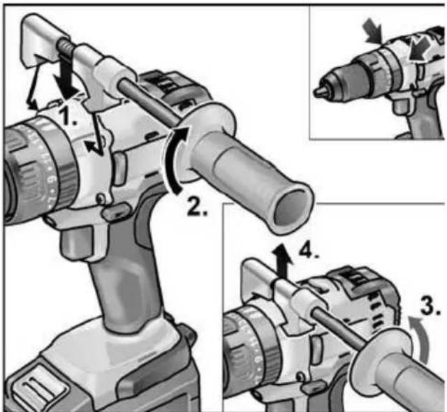
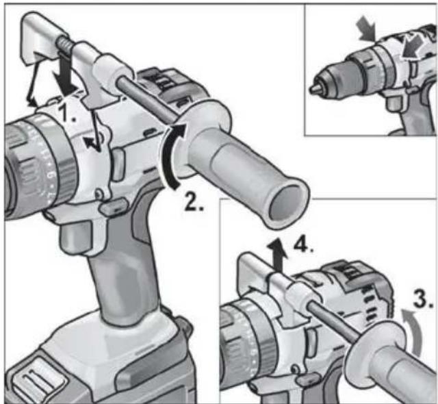
Fitting/removing the auxiliary handle (PD/DD 2G 18.0-EC)
CAUTION!
Use auxiliary handles if these are supplied with the power tool. The loss of control may result in injuries.
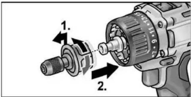
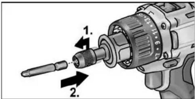
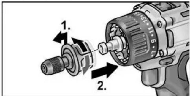
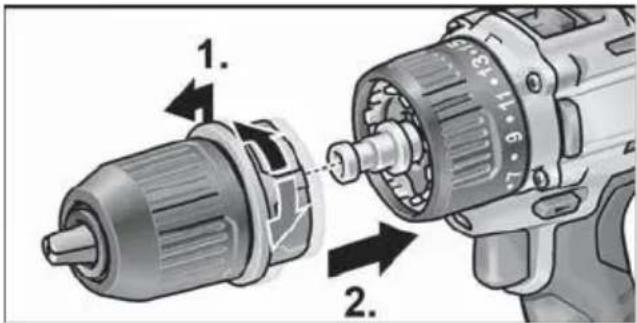
Changeable drill chuck BF 18.0-EC
CAUTION!
Before carrying out any work on the power tool, move the direction preselector switch (2) to the middle position.
Assemble
Pull unlocking ring forwards (1.) and press the drill chuck all the way onto the tool holder (2.).
- Release unlocking ring. Check that the drill chuck is locked in position.

Disassemble
Pull unlocking ring forwards and remove the drill chuck.
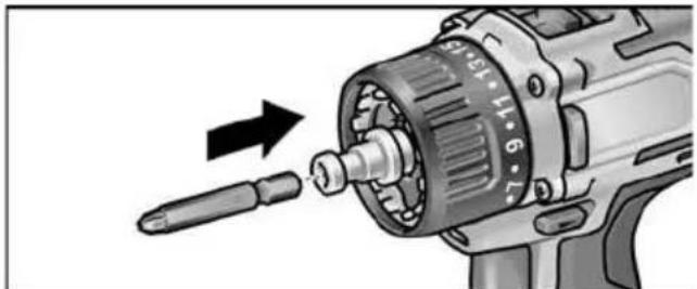
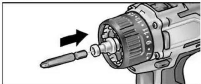
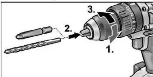
Inserting the tools
Drill bits with a diameter of 1.5 - 13mm 1 / 2 screwdriver bits and 1 / 2 bit holders are securely held in the drill chuck.
Grip the power tool firmly with one hand and turn the chuck with the other hand.
- Turn counterclockwise to open the chuck further.
- Turn clockwise to close the chuck.

Insert the tool.
Close the chuck fully.
i NOTE
Carry out a test run to check that the tool is chucked in the centre.
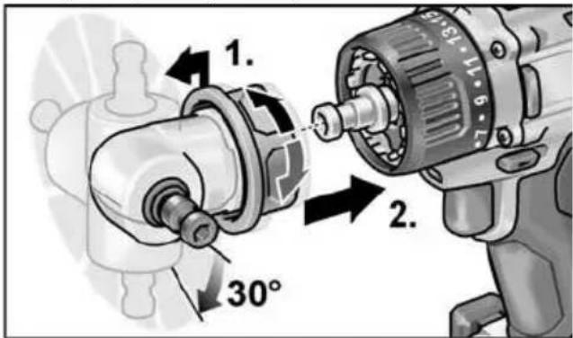
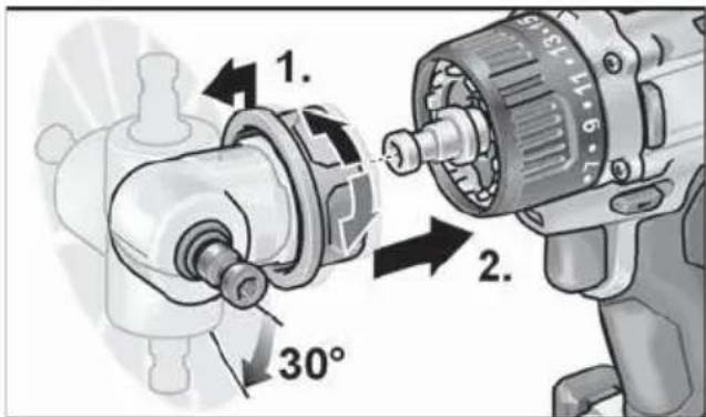
Angle attachment WV 18.0-EC
CAUTION!
Before carrying out any work on the power tool, move the direction preselector switch (2) to the middle position.
The angle attachment facilitates working in places which are difficult to access.
The angle attachment can be locked in different 30^ angular positions.
Assemble
Pull unlocking ring forwards (1.) and press angle attachment all the way onto the tool holder (2.).
Lock angle attachment in the required angular position.
Release unlocking ring. Check that the attachment is locked in position.

Disassemble
Pull unlocking ring forwards and remove angle attachment.
Inserting the tools
The angle attachment has a 12 tool holder. Screwdriver bits and bit holders are securely held in the tool holder.
The keyless chuck (see "Changeable drill chuck BF 18.0-EC") or the bit holder (see "Bit holder attachment BV 18.0-EC") can be mounted on the angle attachment.

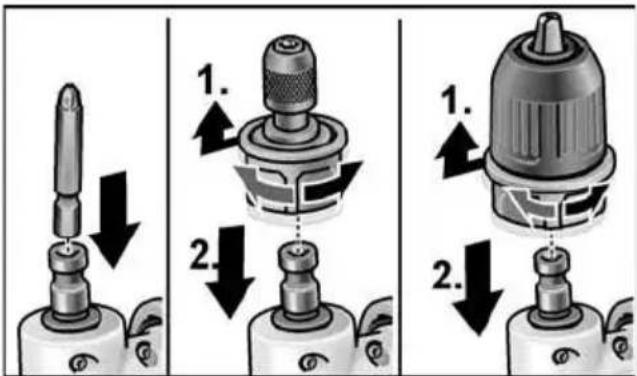
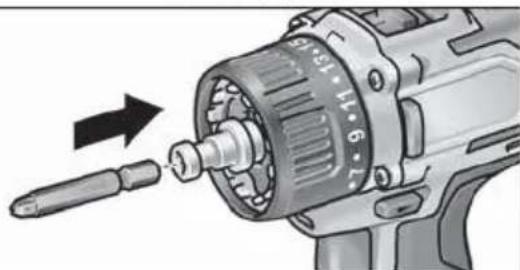
Bit holder attachment BV 18.0-EC
CAUTION!
Before carrying out any work on the power tool, move the direction preselector switch (2) to the middle position.
Assemble
Pull unlocking ring forwards (1.) and press bit holder attachment all the way onto the tool holder (2.).
- Release unlocking ring. Check that the bit holder attachment is locked in position.
Disassemble
Pull unlocking ring forwards and remove bit holder attachment.
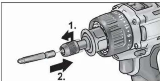
Inserting the tools
The bit holder attachment has a 12 tool holder. Screw-driver bits are securely held in the tool holder.
Pull tool lock forwards (1.) and press in the tool all the way (2.).
Release tool lock.
To remove the tool, pull tool lock backwards.
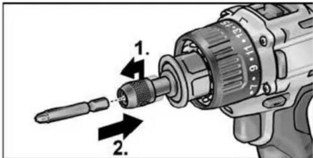
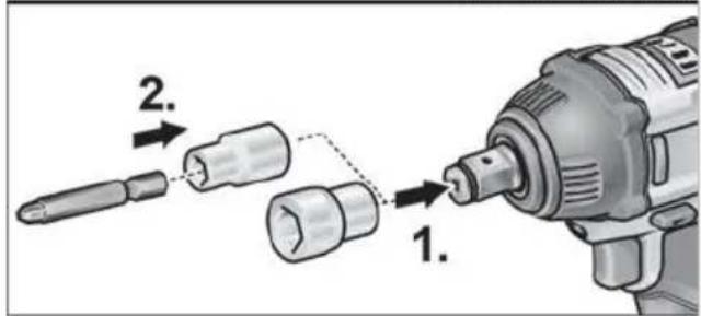
Tool change
CAUTION
Before carrying out any work on the power tool, move the direction preselector switch (2) to the middle position.
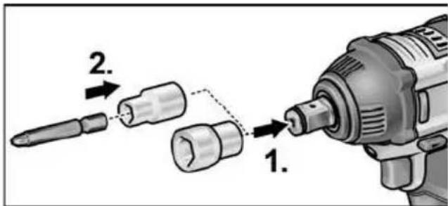
IW 1/2" 18.0-EC:

Push adapter on square drive of impact driver (1.).
Insert tool in adapter (2.).
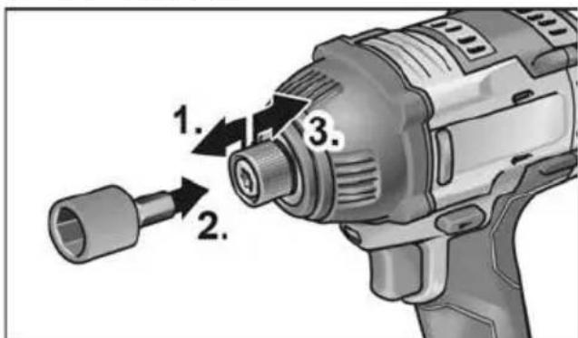
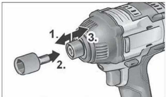
ID 1/4" 18.0-EC:
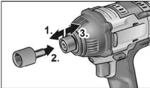
Pull tool lock forwards (1.) and press in the tool all the way (2.).
Release tool lock.
To remove the tool, pull tool lock backwards (3.).
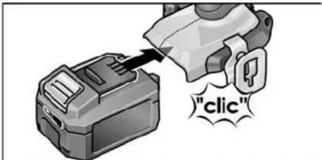
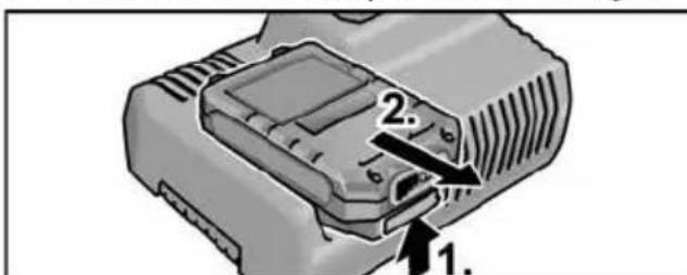
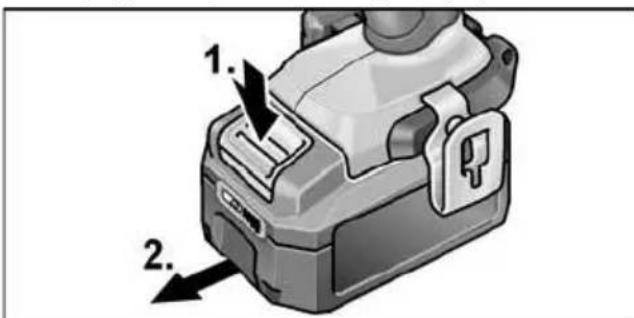
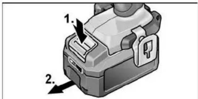
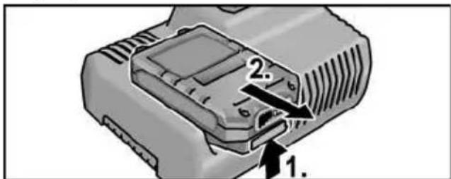
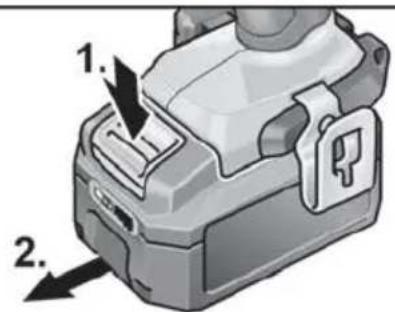
Inserting/replacing the battery
Press the charged battery into the power tool until it clicks into place.
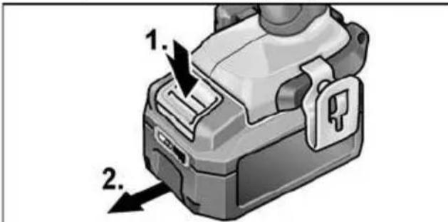
To remove, press the release button (1.) and pull out the battery (2.).
CAUTION!
Protect the battery contacts when the battery is not being used. Loose metal parts may short-circuit the contacts - Explosion and fire hazard!
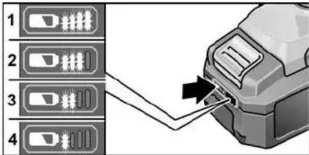
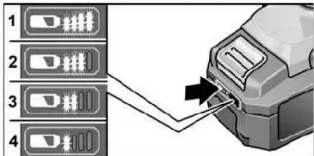
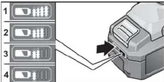
Battery state of charge
Press the button to check the state of charge at the state of charge indicator LEDs.
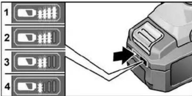
The indicator goes out after 5 seconds. If one of the LEDs flashes, the battery must be recharged. If none of the LEDs light up after the button is pressed, the battery is faulty and must be replaced.
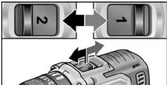
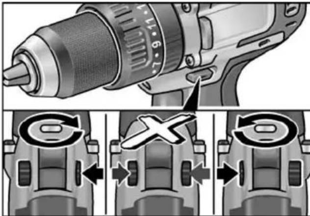
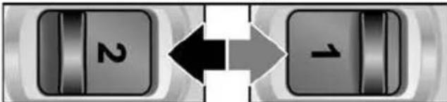
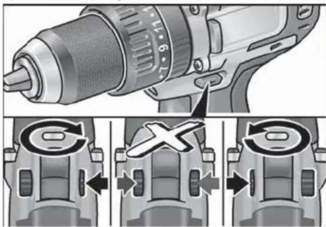
Direction preselection

CAUTION!
Change the direction of rotation only when the power tool is stopped.

Move the direction preselector switch to the required position:
-
Left: counterclockwise (remove screws, release screws)
-
Right: clockwise (drill, insert screws, tighten down screws)
-
Middle: switch-on interlock (tool change, when working on the power tool)
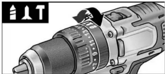
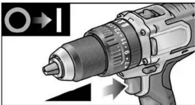
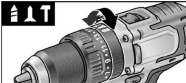
Operating mode (PD 2G 18.0-EC only)

CAUTION!
Change the operating mode only when the power tool is stopped.
Move the operating mode turning dial to the required position.
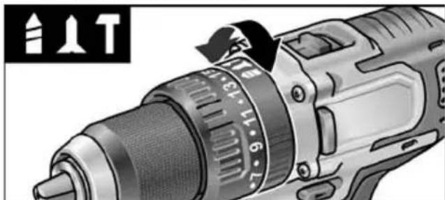

Drilling

Screwing

Impact drilling
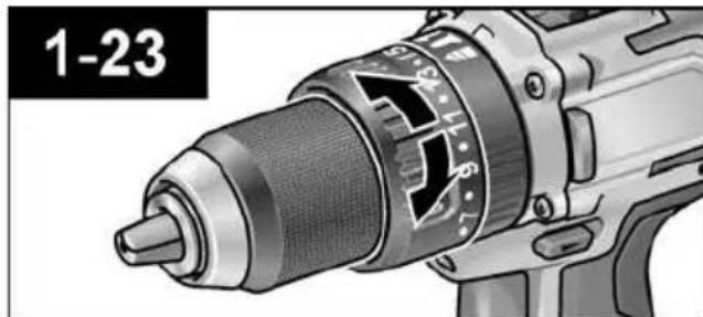
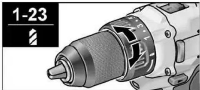
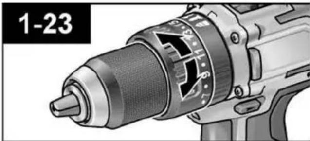
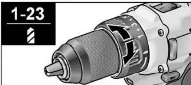
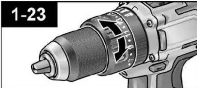
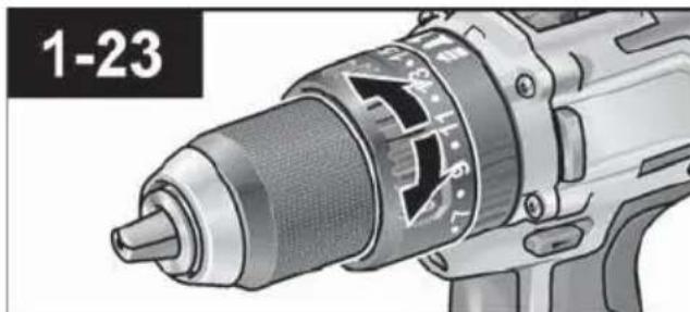
Torque preselection

CAUTION!
Change the torque only when the power tool is stopped.
Move the torque setting turning dial to the required position.
DD 2G 18.0-EC:
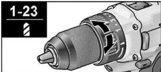
1-23: Screwing

Drilling

NOTE
The safety clutch is deactivated in the
Drilling setting
PD 2G 18.0-EC:
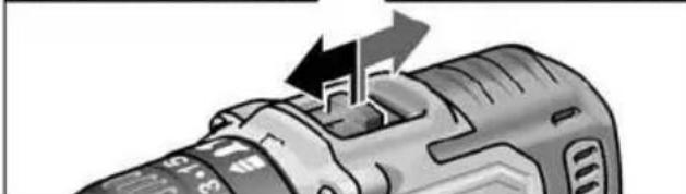
Speed preselection

CAUTION!
Change the speed only when the power tool is stopped.
Move the selector switch to the required stage:
1: Low speed, high torque
2: High speed, low torque
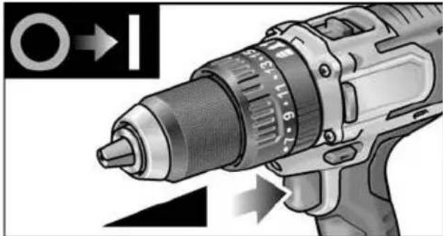
Switching on the power tool
To switch the power tool on:
Press the trigger switch.
The power tool trigger switch allows the operator to increase the speed in increments up to the maximum speed.
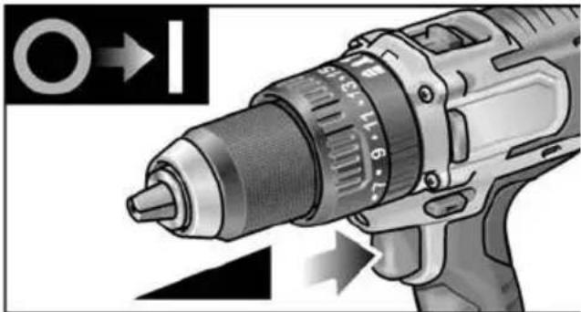
To switch the power tool off:
Release the trigger switch.

NOTE
The power tool is equipped with a brake which stops the cutting accessory as soon as the trigger switch is released.
- When using the power tool continuously, the operator should work primarily with the trigger switch fully depressed.
Workplace lamp on/off switch
- Turn direction of rotation preselector switch (2) to "Forwards" or "Reverse".
- Press electric tool on/off switch (1)
Workplace lamp lights up
- Release electric tool on/off switch (1)
- Workplace lamp goes out automatically after approx. 10 sec.
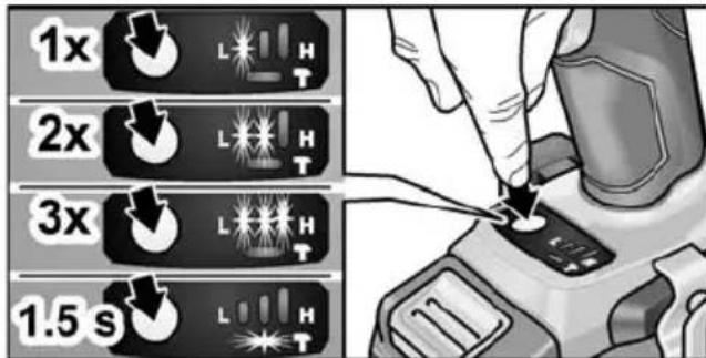
Speed and torque preselector switch IW 1/2" 18.0-EC / ID 1/4" 18.0-EC
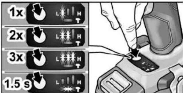
Change speed/torque
- Activate on/off switch (1)
-
Press mode switch briefly (approx. 0.5 sec.).
-
An LED lights up - torque:
| IW 1/2" 18.0-EC: 150 Nm / 1500 rpm |
| ID 1/4" 18.0-EC: 60 Nm / 1500 rpm |
-
Press mode switch briefly
-
Two LEDs light up - torque:
| IW 1/2" 18.0-EC: 180 Nm / 2000 rpm |
| ID 1/4" 18.0-EC: 105 Nm / 2000 rpm |
-
Press mode switch briefly
-
Three LEDs light up - torque:
| IW 1/2" 18.0-EC: 250 Nm / 2500 rpm |
| ID 1/4" 18.0-EC: 225 Nm / 2500 rpm |
-
Press mode switch briefly
-
An LED lights up - torque switches back to:
| IW 1/2" 18.0-EC: 150 Nm |
| ID 1/4" 18.0-EC: 60 Nm |
Torque can be increased again as described. During reverse operation of the electric tool - which only has one speed - the LEDs in the base go out automatically.
Change single impact mode to impact driver mode
Press mode switch for approx.
1.5 seconds.
- LED mode indicator lights up - single impact mode active
- LED mode indicator not lit - impact driver mode active.
Working with the power tool

CAUTION!
Before carrying out any work on the power tool, move the direction preselector switch (2) to the middle position.
i NOTE
To facilitate handling of the appliance when inserting screws, the screwdriver bit can be inserted directly into the tool holder of the appliance.
- Assemble the tool head (drill chuck, angle attachment, bit holder attachment).
- Insert the battery.
- Insert the tool (drill bits, srewdriver bits, bit holders).
- Set operating mode according to the work item (PD ... only).
- Set torque preselection to the required setting.
- Set speed to the required setting.
- Set the required direction of rotation.
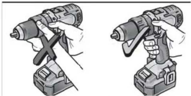
- Hold the power tool with one hand on the handle and assume the working position. If the power tool is running, never actuate the direction preselector switch or torque setting turning dial.

- Switch on the power tool.
At the end of work:
10. Release the trigger switch.
11. Move the direction preselector switch (2) to the middle position.
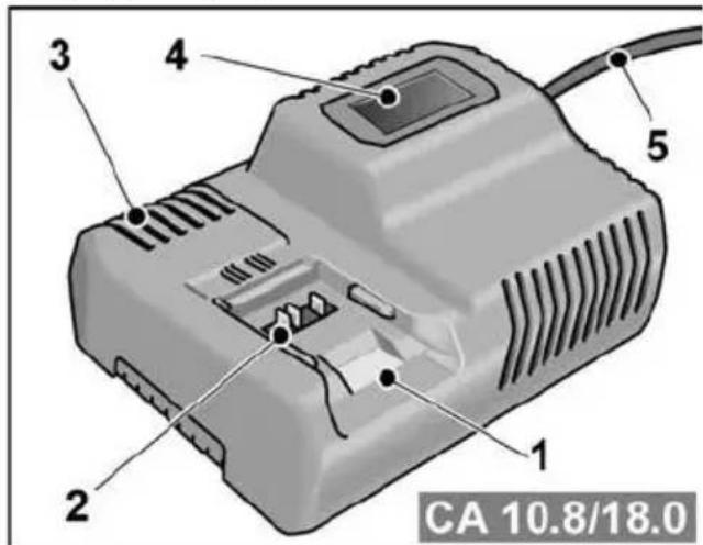
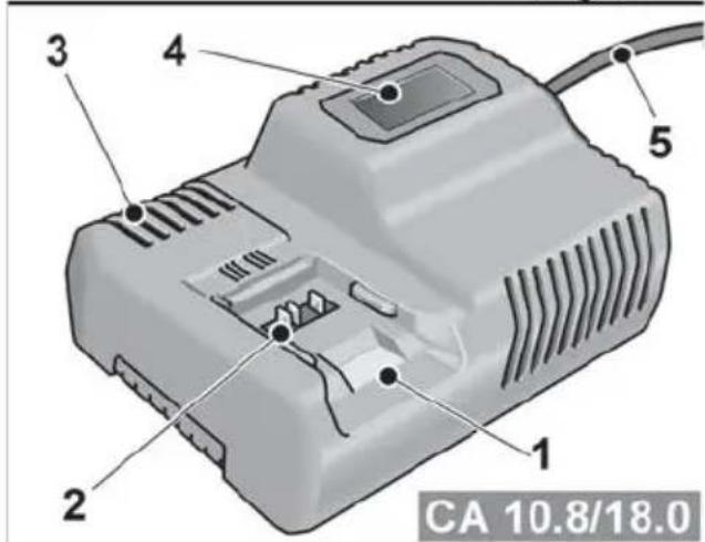
Charger
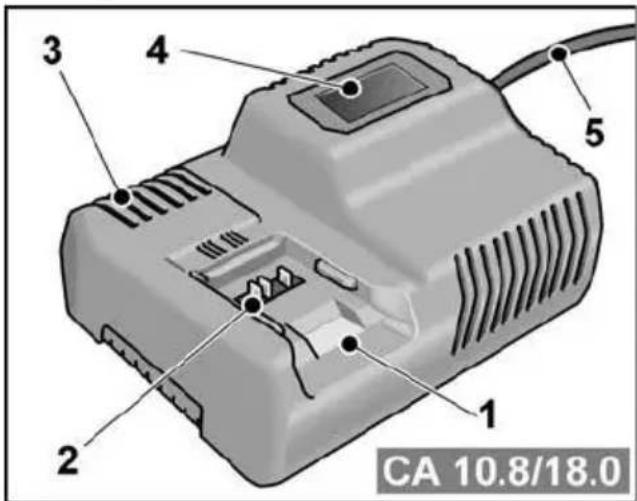
1 Insertion slot for battery
2 Contacts
3 Ventilation slots
4 Operating state display
5 Power cord with mains plug
The CA 10.8/18.0 charger is designed to charge FLEX batteries of the following types
- AP 10.8 (2.5 Ah),
- AP 18.0 (2.5 Ah),
- AP 10.8 (5.0 Ah),
- AP 18.0 (5.0 Ah).
Tips for a long battery service life
CAUTION!
- Never charge batteries at temperatures below 0^ or above 55^ .
- Do not charge batteries in environments with high air humidity or ambient temperature
- Do not cover batteries and the charger during the charging process.
- Pull out the charger mains plug at the end of the charging process.
Battery and charger heat up during the charging process. This is perfectly normal! Lithium-ion batteries do not exhibit the established "memory effect". Nevertheless, a battery should be completely discharged before charging and the charging process should always be fully completed.
If batteries are not used for an extended period of time, store them partially charged in a cool place.
Charging process

CAUTION!
Insert only original batteries in the supplied charger.
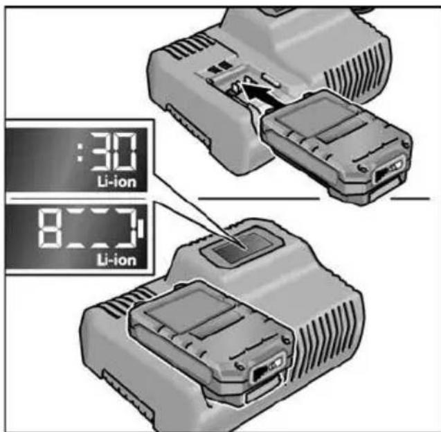
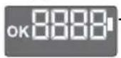
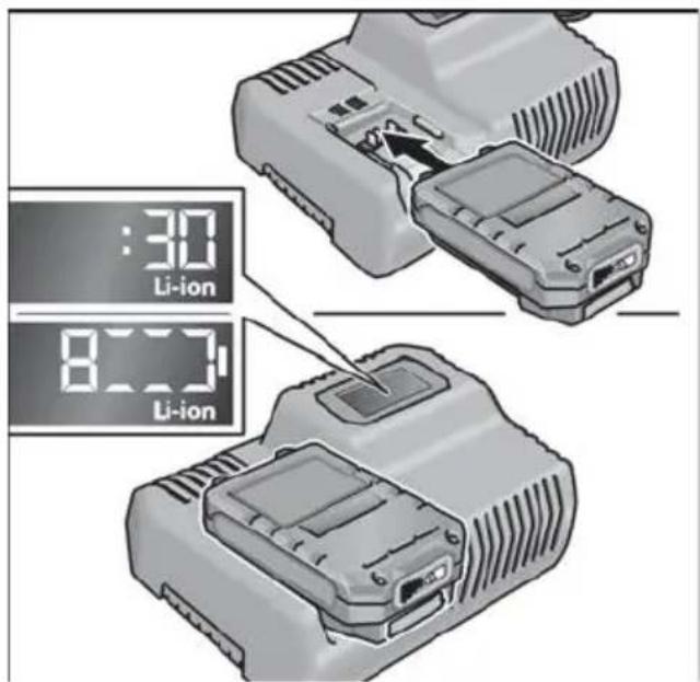
Insert the charger mains plug. The display backlighting lights up green for 2 seconds and then goes out again. OK is displayed.
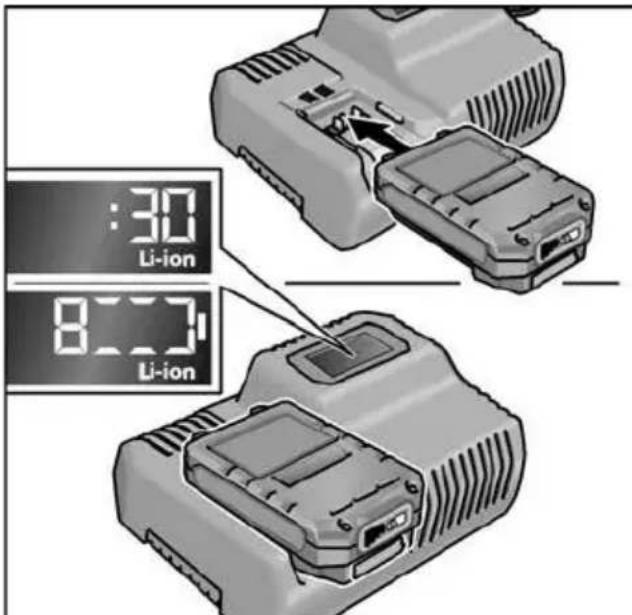
Insert the battery fully into the charger until it clicks into place.
The time remaining in the charging process (until the battery is fully charged) and a graphic representation of the state of charge are shown alternately in the display.
-
The display backlighting lights up orange when the battery is charged less than 80% .
-
When the battery charge reaches 80% the display lights up green and OK is indicated.
The battery is fully charged when the display appears.
The green backlighting goes out after a short time.
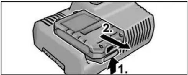
Remove the battery from the charger.
Pull out the mains plug.

NOTE
If the display flashes after the battery is inserted in the charger, there is a fault in the battery or in the charger.
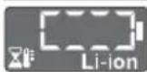
Display flashes slowly. Backlighting orange.
The battery is too hot or too cold. The charging process starts when the battery reaches the charging temperature (0^ 55^)

Display flashes rapidly. Backlighting red.
Remove the battery from the charger and insert again. If the same display persists, the battery is faulty. Replace the battery or have it checked at an authorised repair shop.
If this error message is displayed again with a different battery, this indicates that there is a fault in the charger. Have the charger checked at an authorised repair shop.
Maintenance and care
Cleaning

WARNING!
If metals are worked over a prolonged period, electroconductive dust may become deposited inside the housing. Clean the power tool and ventilation slots at regular intervals. Frequency of cleaning is dependent on the material machined and the duration of use.
Regularly blow out the housing interior and motor with dry compressed air. Keep the power tool running while doing this.
Charger

WARNING!
Before performing any work, pull out the mains plug. Do not use water or liquid detergents.
Remove dirt and dust from the housing with a brush or a dry cloth.
Repairs
Repairs may be carried out by an authorised customer service centre only.
Spare parts and accessories
For other accessories, in particular cutting accessories, please refer to the manufacturer's catalogues.
Exploded drawings and spare-part lists can be found on our homepage: www.flex-tools.com
Transport
The lithium equivalent content of the batteries contained in the scope of delivery is below the relevant limit values. Therefore the battery as a separate component and the power tool with its scope of delivery are not subject to national or international dangerous goods regulations. If several devices containing lithium-ion batteries are transported, these regulations may become relevant and require special safety measures (e.g. for the packaging). In this case acquaint yourself with the regulations that apply to the country of use.
conformity
We declare on our sole responsibility that the product described in "Technical data" conforms to the following standards or normative documents:
EN 62841 according to the provisions of Directives 2014/30/EU, 2006/42/EC, 2011/65/EU.
Responsible for technical documents: FLEX-Elektrowerkzeuge GmbH, R & D Bahnhofstrasse 15, D-71711 Steinheim/Murr


Eckhard Ruhle
Manager Research & Development (R & D)
Klaus Peter Weinper
Head of Quality
Department (QD)
- mains operated power tool by removing the power cord,
battery operated power tool by removing the battery.
EU countries only.
Do not dispose of electric power tools in the household waste! In accordance with the European Directive 2012/19/EU on Waste Electrical and Electronic Equipment and its incorporation into national law, used power tools must be collected separately and recycled in an environmentally friendly manner.
Raw material recovery instead of waste disposal.
Device, accessories and packaging should be recycled in an environmentally friendly manner. Plastic parts are identified for recycling according to material type.
WARNING!
Do not throw batteries into the household waste, fire or water. Do not open disused batteries.
Accumulators/batteries should be collected, recycled or disposed of in an environmentally friendly manner.
EU countries only.
In accordance with the European Directive 2006/66/EC on Waste Electrical and Electronic Equipment and its incorporation into national law, defective or used batteries must be collected separately and recycled in an environmentally friendly manner.
i NOTE
Please ask your dealer about disposal options.
Exemption from liability
The manufacturer and his representative are not liable for any damage and lost profit due to interruption in business caused by the product or by an unusable product. The manufacturer and his representative are not liable for any damage which was caused by improper use of the product or by use of the product with products from other manufacturers.
Table des matieres
Symbolesutilisés 30
-TroisLEDsallument-Couple:
| IW 1/2" 18.0-EC : | 250 Nm / 2500 min-1 |
| ID 1/4" 18.0-EC : | 225 Nm / 2500 min-1 |
- AP 10.8 (2,5 Ah),
- AP 18.0 (2,5 Ah),
- AP 10.8 (5,0 Ah),
- AP 18.0 (5,0 Ah).
Klaus Peter Weinper
Head of Quality
Department (QD)
Manager Research & Development (R & D)
Klaus Peter Weinper
Head of Quality
Department (QD)
18.12.2017
- AP 10.8 (2,5 Ah),
- AP 18.0 (2,5 Ah),
- AP 10.8 (5,0 Ah),
- AP 18.0 (5,0 Ah).

Eckhard Ruhle
Manager Research & Development (R & D)
Klaus Peter Weinper
Head of Quality
Department (QD)
DD 2G 18.0-EC is bested
PD 2G 18.0-EC is bestemd
Manager Research & Development (R & D)
Klaus Peter Weinper
Head of Quality Department (QD)
18.12.2017
- AP 10.8 (2,5 Ah),
- AP 18.0 (2,5 Ah),
- AP 10.8 (5,0 Ah),
- AP 18.0 (5,0 Ah).
Anvisninger for lang akku-levetid

FORSIGTIG!
Montere/demontere tilleggshandtak (PD/DD 2G 18.0-EC)
FORSIKTIG!
- AP 10.8 (2,5 Ah),
- AP 18.0 (2,5 Ah),
- AP 10.8 (5,0 Ah),
- AP 18.0 (5,0 Ah).
Henisninger for lang batteri-levetid

FORSIKTIGI
Lad aldri batterier ved temperaturer under O ^ C ell over 55^
- Lad/DDi kke baterier i omgivelser med hoy luftfuktiget ellher hye omgivelsestemperaturer.
- Dekk wurde tileri og ladeapparat under ladingen.
- Trekk ut nettstopslet til ladeapparatet etter at ladingen er fertig.
Under ladingen blir batteriet og ladeapparatet varmt. Der er normalt!
- AP 10.8 (2,5 Ah),
- AP 18.0 (2,5 Ah),
- AP 10.8 (5,0 Ah),
- AP 18.0 (5,0 Ah).
Klaus Peter Weinper
Head of Quality
Department (QD)
18.12.2017
Endast for EU-stater.
Endast for EU-stater.
- AP 10.8 (2,5 Ah),
- AP 18.0 (2,5 Ah),
- AP 10.8 (5,0 Ah),
- AP 18.0 (5,0 Ah).
Ohjeita akun kestoän pidentämiseen
VARO!
2 Diakottns Tpoetiloyns opac TEPOTPOPHC
3 1 α κ ο π T n
18 Mntatapia ivvov vioiou (5,0 Ah)
19 ravzoc avaptnngns 6wv
20 Biδαστερεωσηξ
21 YtOdoxn mUTns BiDomega
Oδnyiες xρήσης
Piv t n 0eon o e λeitoupyia
Meta to TeLoos Tns Epyaoiaic:
- Aφησετον διακόπητη ελεύθερο.
- TupioTe To diakottn TpoeTIAoynC opac TepiotpOoNc (2) Otn mEoaia theon.
Σuσκευή φόρτιας

- AP 10.8 (2,5 Ah),
- AP 18.0 (2,5 Ah),
- AP 10.8 (5,0 Ah),
- AP 18.0 (5,0 Ah).
Ytioeicysia eyaan diapkeia zwo n ts mntatapiac

PIPOEOXH!
Klaus Peter Weinper
Head of Quality
Department (QD)
18.12.2017
- Mod salterine kisa sure basin -iki LED yanar -tork:
| IW 1/2" 18.0-EC: | 180 Nm / 2000 dev/dak |
| ID 1/4" 18.0-EC: 105 Nm / 2000 dev/dak | |
4.Mod salterine kisa sure basin -UCLED yanar-tork:
| IW 1/2" 18.0-EC: 250 Nm / 2500 dev/dak |
| ID 1/4" 18.0-EC: 225 Nm / 2500 dev/dak |
- Mod Şalterine kisa sure basin
- Bir LED yanar - tork yeniden olur:
| IW 1/2" 18.0-EC: 150 Nm |
| ID 1/4" 18.0-EC: 60 Nm |
Klaus Peter Weinper
Head of Quality
Department (QD)
- AP 10.8 (2,5 Ah),
- AP 18.0 (2,5 Ah),
- AP 10.8 (5,0 Ah),
- AP 18.0 (5,0 Ah).
Klaus Peter Weinper
Head of Quality
Department (QD)
18.12.2017
Klaus Peter Weinper
Head of Quality
Department (QD)
-
- 18.
- AP 10.8 (2,5 Ah),
- AP 18.0 (2,5 Ah),
- AP 10.8 (5,0 Ah),
- AP 18.0 (5,0 Ah).
Klaus Peter Weinper
Head of Quality
Department (QD)
18.12.2017
Klaus Peter Weinper
Head of Quality
Department (QD)
18.12.2017
- AP 10.8 (2,5 Ah),
- AP 18.0 (2,5 Ah),
- AP 10.8 (5,0 Ah),
- AP 18.0 (5,0 Ah).
Klaus Peter Weinper
Head of Quality
Department (QD)
18.12.2017
- AP 10.8 (2,5 Ah),
- AP 18.0 (2,5 Ah),
- AP 10.8 (5,0 Ah),
- AP 18.0 (5,0 Ah).
Nasveti za dolgoŽivljenjsko dobo akumulatorske baterije
POZORI
Klaus Peter Weinper
Head of Quality
Department (QD)
18.12.2017
Introducerea sculelor
Introducerea sculelor
Introducerea sculelor
Introduci completeness of the system.
EN 62841 conform prevederilor
Directivei 2014/30/UE, 2006/42/CE, 2011/65/UE.
Responsabili pentru documento tehnice: FLEX-Elektrowerkzeuge GmbH, R & D Bahnhofstrasse 15, D-71711 Steinheim/Murr


Eckhard Ruhle
Manager Research & Development (R & D)
Klaus Peter Weinper
Head of Quality
Department (QD)
18.12.2017
Noctabraye/cmraHa ha akymylaTophata 6aTepey
HaTnchete 3apeHeHaTa akymyIaTOPHa 6aTePnI Do IbJIHOTo fIKCupaHe B eJek- TPOINHCTpyMeHTa.

3a cBaJIaHe HaTnChTe 6yToHa 3a De6JIOKupane (1.) n N3TerIeTe akymyIaTOPHata 6aTePna (2.).

BHIMAHVE!
Пи ИиЗПОЛЗВаHe OБеЗОпаСЕТ КОТАКТITE Ha akIMyIaTOpHaTа bATEрИ. XЯбавITEMetaJIHnЧаCTN MOrATДa 3akbCrt KOHTAKTITE,IMa ONaCHOCT OT EKcIIIO3NЯ NNoXap!
CbctoHne Ha 3apeKdaHe Ha akymylaTopa
Upe3 HaTnCKaHe Ha 6yToHa nO CBeTO- DIOIte Ha INDkATOpa 3a CBCTOARHeTO Ha aKymJaTOpHata 6aTePnA MoKe Da ce npOBepn CBCTOARHeTO Ha 3apeJdaHe.
HndkaTopbYracBa cneI 5 cekyHn. Ako eINH OT CBeToNDOnTe Mna, akymyNaTopHaTa 6aTePn Tp6Ba Da ce 3apeiN.AKO cIeH HATnCKaHeTO Ha 6yToHa He CBeTHe CBeToND,akymyNaTopHaTa 6aTePn E DeEeKTHa N Tp6Ba Da ce CMeHN.
I36op Ha nocoka Ha BbptHe
BHIMAHHE!
PpomeHnTe Nocokata Ha BbptHe cAmO npN CnpraNo NonoJxHne Ha eNeKTPONHCTpyMeHTa.

I NocTabete npeBknHouBaTeTn 3a H36Op Ha Nocoka Ha BbptHe Ha HyxHaTa No3nU:
- BЯBO: cpeu yacOBHnKOBaTa CTeJIka (pa3BnBaHe Ha BNHTOBe, pa3Xna6BaHe Ha BNHTOBe)
- BdЯсно: no yacOBHnKOBaTa CTpeNka (npo6BaHe, 3aBnBaHe Ha BnHTObe, 3aTЯRaHe Ha BnHTObe)
- B cpeata: 6IOKupaHe Ha BKIOUcBaHeto (CMraHa Ha INCTpyMeHT, pRn BCRAKBN DeINHOCTn PO eNEKTPOINHCTpyMeHTa)
Pexim Ha pa6oTa (cAmO PD 2G 18.0-EC)
BHIMAHHE!
PpomHeIte pexima Ha paobota cmo npn cnprn eNekTpOHCTpyMeHT.
IocTabete BbpTua npbcteh 3a pexmHa paOta Ha HyxHaTa No3uia.
1: npo6nBaHe
N:3aBnHTBaHe
T: ydapHo npo6nBaHe
I36op Ha BbptTmOMeHT
BHUMAHVEI
PpomeHnTe BbptAunMoneH CAmO npn cnpan eNekTpOHCTpyMeHT.
IocTaBete BbptTnna npbCTeH 3a HactpoKa Ha BbptTnna MOMeHT Ha HyxHaTa N03nra.
DD 2G 18.0-EC:
1-23:3aBnHTBaHe
B: npo6nBaHe
i YKA3AHHE
B no3nua 3a npo6uBaHe cOpNKUHOHnT CbeDnHTeI e DeakTNBnpaH.
PD 2G 18.0-EC:
U360p Ha ckopoCT

BHIMAHVE!
PpomeHnTe cKOpocTtca cMo npCnpaI eNeKTponHCTpyMeHT.

IocTaBeTe npeBkJIIOuBaTeIa 3a I36Op Ha Heo6xOIMMaTcTeNEH:
1:6abha ckopoCT, BnCOK BbPTaMOMeHT
2:6bp3aCKOPOCT, HNCbK BbpTAA MOMEHT
BknIOUcBaHe Ha eNeKtpOnHcTpymeHTa
BknuBaHe Ha ypea:
HaTnCHTe npeBKnIOyBaTeJIa. PpeBKnIOyBaTeJIaT Ha eNEKTPoINHCTpyMeHTa N03BOJRA Ba 6e3CTeNEHNO yBeNlUaBaHe Ha o6OpOTnte DO MaKcImaJIHa CToIHOCT.
N3KJIIOUyBaHe Ha ypeJa:
OTnycHete npeBkIIOUbaTeNa.
i YKA3AHVE
- EneKtpOnHcTpymeHTbT pa3nonara cbc CnnpaUka, KOrTO BeHara Cnnpa N3N0N3BaHnU HcTpymeHT CneI OTnyckaHTo Ha npeBknIOuBaTeJI.
- Pn IbIro n3noJ3BaHe Ha eNeKtpOnHCTpyMeHTa Tp8Ba Da ce pa6OTN pEnMuyEcTBeHO C HATNCHaT DOKpaN pEBKNIOyBaTeJ.
BkIIOUbaHe/IN3KJIIOUbaHe Ha OCBETJIeHNeTo Ha pa6OTHO MRCTO
- Превкючete КОЧЕТо 3a ИЗБОР Ha посока淘汰 Вьртейн (2) в положене "Haнред" Или "Haэд".
- HaTnchHeTe KOnYeTo 3a BKnIouYBaHe/ n3KJIIOUyBaHe (1)Ha eJKeKTPoINHCTpyMeHTa -OcBETJeHNeTo Ha pa6OTHOTo MrcTO CBETN
- OTnycheTe KOnyeTo 3a BKnIOUbaHe/ n3KnOuBaHe (1) Ha eJIeKTPoINHCTpyMeHTa -OcBETIeHneTo Ha pa6OTHO To mAcTo aBTOMaTNUHO yracBa cIed OKoJIo 10 cek
I36op Ha o6opOTn IN BbPTaMOMeHT IW 1/2" 18.0-EC / ID 1/4" 18.0-EC
IpeBknHoyBaHe Ha o6OpOTNe / BbptTnMOMeHT:
- BkIIOUeTe KOJIeTo 3a BkJIIOUBaHe / n3KJIIOUBaHe (1)
-
HatncheTe 3a kpaTko konyeTo 3a peXIM (ok.0,5 cek).
-
EAnH CBeToIOnOcCBeTn - BbPTruMOMeHT:
| IW 1/2" 18.0-EC: | 150 Nm / 1500 min-1 |
| ID 1/4" 18.0-EC: | 60 Nm / 1500 min-1 |
- HaTnCHeTe 3a KpaTKO KOnyeTo 3a peXIM -Ba CBeTOndoJa CBET- BbPTaM MOMENT:
| IW 1/2" 18.0-EC: | 180 Nm / 2000 min-1 |
| ID 1/4" 18.0-EC: | 105 Nm / 2000 min-1 |
- HatncheTe 3a KpaTko KonyeTo 3a peXIM - TpN CBeToOnoJa CBeTt - BbPTruM MOMENT:
| IW 1/2" 18.0-EC: | 250 Nm / 2500 min-1 |
| ID 1/4" 18.0-EC: | 225 Nm / 2500 min-1 |
- Hatnche 3a KpaTko KonyeTo 3a peXnM -EINH CBeToNDIOcBETN -BbPTaUNr MOMENT Ce BpbUca O6paTHO Ha:
| IW 1/2" 18.0-EC: 150 Nm |
| ID 1/4" 18.0-EC: 60 Nm |
BbptraaT MOMENT MOKe Da ce yBeJIuH OTHOBO CnopeI ONIcaHOTo.
Korato eIeKtpOnHCTpyMeHTbT pa60Tu Ha 3aJeH XoI, ToI IMa cAmO eHa HAcTpOJa Ha 06OpOTte N HampaUTe Ce B OCHOBaTa CBToIDNoY rAcBaT aBTOMaTNUHO.
IpeBknIOUbaHe OT pexnM Ha eINHueh ynap B pexnM Ha ydapeH BNHTOBbPT:
HaTnCHete KOnyeTo 3a peXIM 3a OK.1,5 cek.
-CBeToIIOHaTa HINKaun 3a peKIM CBETN -peKIM Ha eINHueyDap aKTINBEH
-CBeToIIOHaTa HnIkaCnJa 3a peKIM He CBETN -peKIM Ha yIapeH BnHTOBbPT aKTINBEH.
Pa6ota c eNeKtpOnHcTpymeHTa
BHIMAHVEI
IpeHn BCNUKn DeHOCTu NO eNKeTPOHHCTpymeHTa NocTabrYe IpeBKnUyBaTeY3a N36Op Ha Nocoka Ha BbPteHe (2)B CpeHNO NIOXKeHne.
i YKA3AHVE
3a da MoKe pa6oTaT a npu 3aBnHTBaHe da e IIO-JeChA, 6NTbT 3a BnHTOBep T MoKe da CE NOCTABrT INpeKTHO B NocTabKaTa 3a INHcTpymEHT Ha ypeDa.
- MoNTpaIte Hocaya Ha INHCTpyMeHTa (CmeHraCe NaTPOHHK, bTNOBa npNCTaBka, npNCTaBka 3a DbpxaHu ha 6nTOBe).
- NocTaBete akymylaTophata 6aTePnra.
- NocTaBeTe INHCTpymeHT (6ypn, 6NTOBE 3a BNHTOBePT, nbpkaHa 6NTOBE).
- HactpoTe peKIma Ha pa6Ota cbrIaCHO pa6OTHaTata 3aDaay (cAmo PD...).
- HacptpoTe n36opa Ha BbptraM MOMENT Ha Heo6xOaMaTa CTepeH.
- HactpoTe cKOpocTtHa Heo6XoIMaTa CTenH.
- HactpoIte Heo6xOIMaTa nocoka Ha BbptHe.
- XBaHete eNeKTPoHnCTpyMeHTa C eHa pKa 3a pbKOXBaTKaTa N 3aEmTe paOTha No3nUra.
Pn pa6oTeu MOTOp HNKora He 3aDeIcTBaIe IpeBknIOyBaTeJIa 3a 36Op Ha Nocoka Ha BbptHe, pecn. HAcTPOiKaTa Ha BbPTaIu Momet!
- BkIIOUeTe ypeJa.
CneKpaHa pa6oTaTa: - OTnycheTe npBkIIOUbaTeIa.
- Пoctabete npeBknHouBaTeJЯ 3a n36Op Ha nocoka Ha BbPteHe (2)В cpeHNo nOLOXKeHne.
3apraHNO yCTpOiCTBO
1 OTbOp 3a BkapBaHe Ha akymyIaTOPHaTa 6aTePnIa
2 K O H T a K T n
3 BeHTnlaZnOHeH OTBOp
4Диспелза пoka3BaHe Ha pa6OTHOTO CbCTOHHe
5 EneKtpnueckn Ka6eJ c uencen
3apndHOTO yCTpOncTBO CA 10.8/18.0 e nped-Ha3NaueHo 3a 3apeXdaHe Ha FLEX akymyIaTOPn6aTePNOT MOneJInte
-
AP 10.8 (2,5 Ah),
-
AP 18.0 (2,5 Ah),
-
AP 10.8 (5,0 Ah),
-
AP 18.0 (5,0 Ah).
Yka3aHna 3a dIbIbI eKcNIOaTauNoHe HxNBOT Ha aKymyNaTOPHaTa 6aTepy

BHVMAHVE!
- Hukora He 3apejdaite akyMynatopHnTe 6atepn np Temnepatyp npd 0^ pecn. Na 55^
He 3apejdaTe aKymyIaTOPHnTe 6atepnB CpeDa C BucOKa BlaxHOCT Ha Bb3dyxa IIN BUCOKa TEMepaTypa.
He nokpnbaiTe akyMylatopHnTe 6aTeepuN u 3apAHHOT yCTpoiCTBO NO BpeMe Ha npOceca Ha 3apeXdaHe. - Ⅲternayte uencena Ha 3apdHOTO yctpoiCTBO cneI kpaHa npoceca Ha 3apekdahe.
IIO Bpeme Ha npoueca Ha 3apekdahe akyMylaTOPHaTa 6aTePnN 3apdHOTO yCTpoiCTBO ce HarpBaT. Toba e HopMaJIHo!
IITHeBO-IOHHTe aKymlaTopn He noka3BaT u3BeCTHnra "Membp" epeKT. BbnpkToBa akymlyaTophata 6aTeprna Tp8Ba Da ce n3ToUdOKpaN ppeN 3apeXdaHeTO nPpoecbT Ha 3apeXdaHe BnHaRn Tp8Ba Da ce 3aBbPwBa DoKpaN.
Ako akymylnatopnTe 6aTeepn Hma da ce n3no3BaT NO-DbIro BpeMe, 3apeTe rN qactuHNO I rN CbXpaHraBaTe Ha XnaHO.
Ppoec Ha 3apeKdaHe
BHIMAHHE!
BdoctabeHOTo 3apraHOn yCTpOncTB0 nocTabaIte cAmO opuHaJIHN aKymyIaTOPn batepn.
BkapaTe 7eNcena Ha 3apAHOTo yCTpoIcTBO. OHOBOTO OCBeTJIeHne Ha IINCIIeR CBETn 3a 2 CeKHyDn B 3eJEno n CNeI TOBa OTHOBO yracBa. Noka3Ba ce OK.
IocTaBete akymyNaTopHaTa 6aTePnra doФИКСираHTo I B 3aprAnHOTo yCTpOInCTBO.
-Последователно на диспег с
нока3ВAT OCTaTBHOTO Вретраени
На пpoцурарази заразжданe (do
пьното заразжданe
akymулалорна заразери) и графчнo
праздравяны Нссытогиeto Ha
зразжданe.
-ФОHOBOTO OCBETJIENHe HaДИСПЛЯ CBETN B OPAHKeBO, aKO akymlyaTOPHaTa 6aTePnE 3apeDeHa HaNo-MaNKo OT 80%
-OT 80% akymylaTopeH 3apd DnCnJIeT CBETN B 3eJIeHO n Ce noka3Ba OK.
AkymylaTopHaTa 6aTepe nHaNbJIHO 3apeJeHa, aKO ce NOKa3Ba INHnKaCnTa

3eHTo oHOBO OCBtJeHne yracBa cIeKpaTKO.
I3BaTeAkyMylaTopHata6aTePnO 3apAnHOTo yCTpOiCTBO.
N3ternete uencena.
i YKA3AHMEIS
Ako cnei noctabraHTo Ha akymyIaTophata
6atepna B 3apdHOTO yCTPOcTBO dncnneT
Mira, HAnuie e rpeWka B akymyIaTophata
6atepna nn no 3apdHOTo yCTPOcTBO.
ДиСпгЯТ MURAбавно.ФОHOBOTOCBETПЕHNEeOpaHKeBO.
AkyMnyatopnata 6atepna e TBbpde TOnna, pecn. TBbpde ctydeHa. Korato akyMnyatopnata 6atepna doCTnHe TemnepaTypata Ha 3apeKdahe (0^ 55^) npocbT Ha 3apeKdahe 3anoYBa.

ДиСПЕТ MИRA 6БР30.ФОНБОТO OCBETПЕHIEe uepBeHo.
I3BaTe N OTHOB CNOXeTe aKymyNaTOPHaTa 6aTePnO rT 3apAnHOTO yCTPOINCTBO.AKO INDnKaunra TocAHe cbuata,akymyNaTOPHaTa 6aTePnE e deFekTHa.CmeHete akymyNaTOPHaTa 6aTePnN IINr 3aHeceTe 3a npOBepKa B CneuaJIIN3npaH cepBn3.
Ako cbltoTo cboobseHne 3a rpeuka ce NOKa3Ba n Cdpyra akymylatopha batepna, 3apnHOTO yCTPOIcTBo e depeKTHO. 3aHeceTe 3apnHOTO yCTPOIcTBo 3a npOBepKa B CneuaNn3npaH cepBn3.
O6cnyXBaHe n noDprbXka
NouchTaHe
IPEyIPEXHEHNE!
IpnOcbpaobTaHHeToHaMetaII npn HHTeH3INBHO N3IOJ3BaHe BbB BbTpew-HocTTa Ha KOpnyCa MoKe Da Ce HATpyna npoBODIM npax. NoucTbaIte ypeDa n Bb3dUuHInTe OTBOPn peDOBHO.YecTOTata 3aBnCnOT OcbpaobTaHHeMaTePnaNnOT IpoDbJIxNtEJIHoCTTa Ha N3IOJ3BaHe.
N3dyXbaIe BbTppeuHocTtHa KOpnyCa C MOTOPa Cbc Cyx Bb3dYx.
3apraHNO yCTPOIcTBO
IPEyIPEXHEHME!
PpeiBcKaKbN DeHocTH u3TeTnIte 1e enceHa. He n3no3BaIte Boda nn TeHNOCTBaO CpeIcTBO.
OTctpaHbAte MpbcotnTa n npaxTa OT KopnyCa C YeTnca Nn Cyx NapzaJ.
PemOHn
I3BbPbBaItepeMOHTNcMoBOTOpn3npaHNOPTpOu3BOIDITeJIcneuaIIIN3npaHNCepBu3N.
Pe3epBn qactn npHaJLeXHOCTN
IOnbJIHnTeHN npHaJdNexKHOCTN, I B YacTHOcT INcTpymeHTN 3a UINIOBaHe MOKeTe Da HamePte B KaTaNo3NTe Ha Ipon3BOIDNTeJI.
Сборни чертуни списьни peзервни часно можete за hamepиerte на haшата yeбстара: www.flex-tools.com
TpaHcnpTnpaHe
EKBBaJIeHTHOTOKOJINUYeCTBOJNTNHa CbIbPkaUNTe CeB OxbBaTaNdoCTaBKaTa aKymyLaTOPHNbATEPNeOpEnBaHTHNTe rpaHnHn CTOnHocTN.ETo 3aIo aKymyLaTOPHaTaNbATEPNaTOOTDeJIeH KOMNoHErT, KaKTo N eJIeKTpONHcTPymeHTbT C OxbBaTaN HaIOCTABKa He Ca OBeKT Ha NaUHOHaJIHNTe IIN MExdYHapODHn PpeDnCaHn 3a ONaCHN pOdykTN.
Ipn TpaHcnpTupaHe Ha HЯKoNko ypeDa c IInTneBO-IOHn AkymyNaTopHN BaTeepN Te3n IpreDnncAHnMaORaT Da ca peNeBaHTHn N Da HAnOkaT CneuAHH MePKn 3a 6e3OnacHOCT (HaNP. 3a OnakOBaHeTo). INΦopMnpaTe ce B To3N CnyaJ 3a BaINdHnTe B CTpaHaTa Ha N3PON3BaHe IpreDnncAHn.
Декларачnia 3a СьOTВETCTBNE(E
ДeКларпамесцялataсн endohonnyha OTROBOPHOCT Ye OINcaHnT B «TexHueckn DaHHN» npOdyKT cBbnaJa cBc CJIeHNTe HOpMn IIN HOpMaTHBn DOKyMeHTN: EN 62841В cBoTBetCTBne c pa3npopeIbte Na dInpeKtBn 2014/30/EC, 2006/42/EO, 2011/65/EC.
OTROBOpeH 3a TEXHNueCKNte DOKymeHTN FLEX-Elektrowerkzeuge GmbH, R & D Bahnhofstrasse 15, D-71711 Steinheim/Murr


Eckhard Ruhle
Manager Research & Development (R & D)
Klaus Peter Weinper
Head of Quality
Department (QD)
I3KIIIOUBAHe Ha OTROBOPHOCT
Ipon3BODHTNHEROBITE ppeCTaBNTENHeOTROBAPRT3aHaHecEHNIpyonucHTNPOJNnOPaDNppeKpaTBAHeHa pa6oTa, KOINTO Ca npuHEnOTnpOdykTA NINOT HeBb3MOXHOCTTa daCe n3PON3Ba npOdykTa.
PpOn3BODHTIeTnHerOBtE npEdCTaBNTeHHe OTROBaprT 3a uetN, KOnTO Ca npUHHEnOT He npabOMepHO n3NoJ3BaHe NIN n3NOJ3BaHe B KOMbHaucnC pOdyKTHNa DpyrN pOn3BODHTeHn.
Copepkanhe
IcnoJb3yeMbIe CmBOJIb 297
CnmbolbHa npnbope 297
ДяВашевбezонacHocTи 297
UmbuBbpaun 300
TexHnueckne xapaKTepeNCTnKn 301
ObueyucpoIcTBO n3deJnra 301
Hnctpykqna no 3Kcnpyaatau .303
TexobcnykBaHne uyOd 310
TpaHcnpTnpoBka 310
COOTBeTCTBHe HOpMaM C. 310
YkaaHnno yTnIn3aun 311
NCKJIHoueHHe OTBETCTBeHHOCTn . 311
IcnoJb3yeMbIe CnMBOJIbI

IPEyIpeXeHHe!
Obo3haayet HenocpeCTBeHHO
YrpoKaIOUyIO ONaCHOCTb. HeBbIOnJIHeHne 3TOrO yKa3aHnA MoKeT NOBNeuB 3a CO6oI TAgKeJIbIe TEJIeCHbIe NOBpeXdEHNr IIN dAke CMePTb.

BHIMAHHE!
O603HaayeT BO3MOxHOCTb BO3HKnHOBeHn
ONaCHO CHTyaCNI. HeBbINOJIHeHne 3TOrO
yKa3aHnMoXeT NOBNeYb 3a CO6oI
TeNEChIe NOBpeXdEHNu IIN
MaTePnaJIbHbI yUeP6.

YKA3AHHE
O603HaayaeT COBtI IO NCIOb3OBaHIO IN BaxHyIO IHOpMaHIO.
CnmboJIbHa npnbope

IpeB BBODOM B 3KcNpyaTauHIO npOueCTb INCTpykUHO NO 3KcNpyatauH!
Icnonb3ObaTb 3aunTy dny rna3!

3aunTHbI TpaHcΦopMaTOp c 3aUNTOIOT KOPOTKIX 3aMbIKAHN
3auntntb aKKymyIaTOp OT HArpeBa, B YaactHOCTN OT npMbx COJHeuHbIX Nyei N OrHa. CyueCTByeT pNCK B3pbIbA.
3anpeaaetc 6pocatb aKKymyIaTOp B OROh. CyueCTByeT pNCK B3pbBa.
I3dJIne npedHa3HaeHo TOJbKO IINcNoJIb3OBaHnB NOMeUeHNx. 3anpeuaeTc8 OCTaBnTb I3dJIne IOI DOXKeM. 3JeKTPoNHCtpymENT n aKKy-MyJrTOpbl CNeDyET XpaHHTb B CyNX NOMEUeHNx.

Yka3aHnno yTnJIn3aCn (cm. cTp. 311)!
Hnctpykza nO 3KcnpyaTaau
YCTaHOBka INHCTpyMeHTOB
B CBepnIbHOM nATpoHe HAdeXHO ydePknBaOTcR CBePna DnAmetpom 1,5-13 MM, 6ntbl 12 " n DePkaTeJIb 6NT 12
YdepxnBaJ3JIeKTPoHnCTpyMeHT OJHOykoJ,dpyroPkyoNIOBopauNbAteCBepnIbHbI NaTPOH.
- BpaaaTe npOTnB YacOBo CTpeJIKN, TTO6bI yBeJIuHTb packpbITne CBepINbHOrO nATpoHa.
- BpaaTe no yacOBoCtpeIKe, T06bl 3aKpbItb CBePnIbHbI NaTPOH.
YcTaHOBnTE HhCTpyMeHT.
I OJHOCbIO 3aKpOte CBePJIbHbI naTPOH.
i YKA3AHVE
BbinoHnTe npo6hI nyck, yTO6bl npOBepntb ceHTpnuHOCt b KpePHeHn AHCTpyMeHToB.
YrnoBaHaCauKa WV 18.0-EC
BHIMAHVE!
Ipeed BbINONHeHnEM IIObix pa6oT ha 3NeKTPoHnCTpyMeHTe yCTaHOBNTe IpeeknoYateJIb BbIbopa HnPaBnEHn BpaueHnra (2) B cpeJeEe nOIOKeHne.
YrnoBaHacaKaObIeRyAeTpa60Ty B TpydNoOCTynbIX MeCTax.YrnoByIO HacaKy MoXHo QnKcnpOBaTbB pa3nHybIX YrnoBbIM NpOKeHHx C WaROM 30^
YCTAHOBKa
I IOTaHnTe De6IOKpyUoUee KOJIbO BnepeD (1.) n BdaBnTe yrNoByu HacaNky Do ynpa B 3aJMMHO NaTPOH (2.).
3aФнсUpyTe yrNoByHacaIky B HxHOM yrNoBOM NOIOXeHN.
OTnyctnte de6IokpyuOuee KoIbUo. PpOBepbTe 0KcaUIO.
Chrtne
I OTe Ie6IOKpyUoee KOJIbUO BnepeN CHIMTE yrnoByu HacaKy.
YCTaHOBka HHTpyMeHTOB
YrnoBa HacaKa OchaSeHa 3aXMMbIM NaTPOHOM 12 .B 3aXMMHom NaTPOHe HaDExKHO yDepXnBAOTc6ntbI n DepXkTeNb 6NT.
Ha yrnobyu HacaKy Moxho TaKke
yCTaHOBtB CMeHHbI CBepJIbHbI
natpoH (cM. «CmeHHbI CBepJIbHbI
natpoH BF 18.0-EC») nII n depXaTeIb 6nt
(cM. «HacaKa c depxaTeIem 6nt
BV 18.0-EC»).
HacaKa c ČeρЖaTeJIem 6nT BV 18.0-EC
BHIMAHVE!
Ipeed BbINONHeHem NIObix pa60r Ha 3JIeKTPoHHCTpyMeHTe yCTaHOBHTe IpeekTIOUaTeIb BbIBopa HAppaBHeHnB BpaueHn (2) B CpeJHee NOIOKeHne.
YCTaHOBka
Notaryte De6IokpyuOuee KOJIbcoBnepei (1.) n BdaBnTe HacaKy C depXaTeIem 6nt Do ynpaB 3axmHoi NaTPOH (2.).
OTnyctnte de6IOKpyUoue KoIbUo. IpoBepbTe 0nkcauio.
CHRTNE
I NotaHnTe De6NOKpyUouee KOJIbO BnpeE N CHMnTE HacdKy C depKataeM 6nt.
YCTAHOBKa NHCTpyMeHTOB
HacaKa C depKaTelem 6nt OchaueHa 3axMMbIM NaTPOHOM 12 .B 3axMMHom NaTPOHe HaJExKHOydepXnBAOTc 6NTbl.
I NotaHnTe fHKCaTOP HcTpymeHa BnepeD (1.) n BdaBte HcTpymeHT Do ynpa (2.).
Otnyctnte cTOnOp nHcTpymeHTa.
ДяиЗВLEЧЕнЯИНСТРМЕNTA NOTAHTECTONOPINHCTPМEHTaHa3aJ.
CmeHa pa6oeryo nHcTpymeHa

BHIMAHVE!
Ipeed BbINONHeHnEM JIObix pa60Ha 3JIeKtpOHCTpyMeHTe yCTaHOBNTe IpeekIouateIb BbIbopa HappaBHeHnBApaueHn (2) B cpeidhee nOJoxHeH. IW 1/2" 18.0-EC:
HacaNTb TOPcOBbIM KJIIOu Ha YeTbIPexrpaHHyIO HacaIKy ydapHoro raIKOBePta (1.).
BCTaBnTB INHCTpyMeHT B TOPcObBi KJIIOU (2.).
ID 1/4" 18.0-EC:
I NotaHnTe fNkCatOp nHcTpymeHTa BnepeD (1.) n BdaBnTe nHcTpymeHT do ynpa (2.).
OTnyctnte cTOnOp HnHcTpymEHTa.
ДяиИЗВЕЧЕНИИНСТРМЕNTА NOTAHITECTONOP ИНСТРМЕNTA Ha3aI (3.).
YcTaHOBka/3aMeHa aKKyMylTopa
BCTaBbTe 3apJxHbI aKKymyIaTOp B 3JIeKTPoIHcTpymEHT DoΦnKcaUH.

ДяиИЗВЛЕЧЕнЯHAЖМЛТЕKHОПКI pa36ЮКИРOBКI(1.)иBBIHBTeakKyMyJЯTOp(2.).

BHIMAHVE!
Ha HencnoJb3yemom aKKymJItope 3auntte KOHTaKtbl. OTkpbItbie MetanJnueckne DeTaN MOrY T 3AMKHyTb KOHTaKtbl HApOpOTK, CyuectByET ONaCHOCTb B3pbIBa N BO3ropaHn!
UpoBHeB 3apYda aKKyMylTopa
■Пи Нжати КногнHa CBETOДNOHOM INДИКаTOpe MOXHO NOCMOTpeTb yPOBeH 3apra.
Hndkatop norachet uepe3 5 ckynd. Ecnn Odn H3 CBeToNDIOB Mmraet, aKymyIaTOp Heo6xOIMo 3aprntb. Ecnn nocne haxatna KhoNKn Hn Odn H3 CBeToNDIOB He rOpNT, aKymyIaTOp HeNCnpaBeH nNoDLeXkNT 3ameHe.
Bb6op HanpaBneHn BpaueHn

BHIMAHVE!
Hapabnene BpaueHn MOxHO nepeKIOuATb TOnbKO NOCJe OCTaHOBKn 3NeKTPONHCTpymeHTa.
YcTaHOBInTe NepeKInOuAteIb BbIbOpa HnPaBHeHn BpaUeHn B Heo6XoDmOe NIOJoxKeHne:
-BnEBo: npOTnB YacOBn CTrpeJIKN (BbIBOpaUNBaHne n Ocna6JeHne BnHTOB)
BnpaBO: no yacOBoCtpeKe (CBepJIeHne, 3aBOpauBaHne BnHTOB, 3aTЯuBaHne BnHTOB)
- NocepeHne: 6nOKnPOBka BKNIOUChEnna (3aMeHa INHCTpyMeHTa, BbINOJIHeHne IIO6bIX paBOT Ha 3JIeKTPoINHCTpyMeHTe)
Pezim pa60tbl (ToIbko PD 2G 18.0-EC)

BHIMAHVE!
Pekm pa60bMOxHO nepeKIOyAtb TOnbKO Nocne OCTaHOBKn 3NEKTPoMHCTpyMeHTa.
IpepeBdnte BpaaiooeeecsKoNbO DnBb6opa pexima paobTb B HyxHoe noloxHe.

: CBepeHne

: 3aBOpaUBaHne

: ydaphoe cBepJIeHne
Bb6op kpytJcero MOMeHa

BHIMAHHE!
KpyTAAH MOMEHT MOXHO N3MEHATb TOJIbKO NOCTE OCTAHOBKN 3NEKTPOHCTpymeHTa.
IpepeBEnTe BpaaiooeecKoIbO dIpyuNIOBKn KpyTaeo MOMeHTa B HxHoe NIOXKeHne.
DD 2G 18.0-EC:
1-23:ЗаворачиBaHne

YKA3AHME
B noIoxhenn dnn CBepnHnapeOxpaHHTeNbHa pRNUOHHa MyoTa OTKnIOyeHa. PD 2G 18.0-EC:
BbI6Op cKOpocTn

BHIMAHVE!
CKOPOCTb MOXHO N3MeHrTb TOnbKO NOcNe OCTaHOBKN 3JIeKTPoHCTpyMeHTa.
IpepeBcTe nepeKluOaTeJIb HaHyKbI yPOBeHb:
1: Hn3ka CKOPOCTb, BBICOKN KpyTAAUMOMEHT
2: BBICOKaЯ CkOPOCTb, Hn3Kn KpyTuauMOMeHT
BknIoueHne 3JIeKtpOnHcTpymeHTa
BknHoueHne np6opa:
Haxmte KhoNky nycka. Khonka nyska 3neKtpoHcTpymeHTa no3-BOJrET NO3TaHNO NOBbIwA Tb YnCNo O6OpOTOB Do MaKcMaJIbHOrO 3HaueHnra.
BbiknueHne npnbopa:

- AP 10.8 (2,5 A*u),
- AP 18.0 (2,5 A*u),
- AP 10.8 (5,0 A*u),
- AP 18.0 (5,0 A*u).
Yka3aHnI NO o6eNeueHnIO dInTeJbHOrO cPoka CnyK6bl aKKyMylrTOPOB

BHIMAHHE!
He cneyuET 3apjXaTb aKkymyIaTOpbI npu TemnepaType Hxke O ^ C N Bblue 55 ^ C
- He cIeJyET 3apJxTaB aKKMyJITOpbIB YCIOBnIX IOBbIWeHHoB BJIaXHOCTNINI IN TEMpePaTybpI BO3Iyxa.
He cneDyeT HaKpbIbTa b aKKyMyJrTOpbl N 3apAHOe yCTPOINCTBO BO BpeM 3apAqKn.
- ITOOKOHuaHm3aprAnu3BnKeHTe cTeBOI uTekep 3apraHoro yctpoNCTBa.
Bo Bpem 3apnKn aKKymyIaTOpbl n 3apnHoe yCTpoCTBO HArpeBaIOTc.
3To HopMaJIbHo!
IHTN-NOHbIe aKKMyJrTOpbI He IMeOT
n3BecTHOrO «aΦΦeKTa nAmrTu>. HecMOTp
Ha 3To, aKKMyJrTOp nepeD 3aprKn
Heo6xOIMO NOHOCbIO pa3prNTb,
a npOuceC 3aprKn cNe dyet BCerda
DOBOdntb Do KOHca.
Ecnn aKKymyIaTOpbHe nCNoJb3yIOTcB TeueHne dNITeNbHO BpeMeHN, YactNuHo 3apAInTe aKKymyIaTOpbI IN XpaHnTE INX B npoxJaHOM MeCTe.
Ppocec 3apdKn

BHIMAHVE!
YCTaHaBnBaIte B npnnaeraMoe 3apraHoe YCTpOInCTBO TOnbKO OpiuHaNbHbIe aKKyMyJIaTOpbI.
BcTaBbTe ceTeBOI uTeKepe 3apAnHOrO yCTpoiCTBa.
AkkymyIaTOp NOnHOCTbIO 3apJKeH, KOrDa NOBJIaTeCn INDnKaUaN
3eJeha fOHOBAI NOcBETKa BCKope rachET.
N3BneKeIte aKKyMylTOp n3 3apAnHOrO yCTpoiCTBa.
N3BneKeTe ceTeBOI wTeKepe n3 po3eTKn.
i YKA3AHHE
Ecnn nocne yctaHOBKn aKKymyIaTopa B 3apdHoe yCTpoIcTBo dncnneMuraet, IMeET MeCTO HEnCnpaBHOCTb
aKKymyIaTopa INN 3apdHoro yCTpoIcTBA.

DucnneMmpeHNO Muraet. OpankeBa OHOBa NOcBETka.
AkkymyIaTOp cNtWkOM ropuH nn CnIeKOM XoJOnHbI. KOrda aKcymyIaTOp DOCTURHTempeAtpybI 3apra (0°C...55°C), Nauchetca Ipouecc 3apraKn.

Iucnne6bictpoMuraet. KpacnafoHOBaaNoDCBETka.
I3BNeKeITe aKKyMnyTOp n3 3apJHOrO yCTpOiCTBa nCHOBa yCTaHObITE erO. Ecnn INdNkaZn He MeHReTcR, aKKyMnyTOp HEnCnpaBeH. 3aMeHnTe aKKyMnyTOp nIN CdaTe ero Ha npOBepKv B CpeuHaN3uPoBaHHyIO MaCTepCKYIO.
Ecn np3apdKe dpyrOro aKKymyIaTopa
NoBnEeTcTaKoe Xe COoBueHne 6
Ownke,HeNCnPabHO 3apdHoe yCTPOIcTB0.
CdaTe 3apdHoe yCTPOIcTB0 Ha npoBepky B
CpeuHaN3npOBaHHyo MaCTepCKyIO.
TexobnykBaHne uyxod
YnCTka

NPEyIIPEXKDEHME!
PnOcbpOkeMeTAnIOB B 3KCTpeMaIbHbIX CnyaX BHyTPN KOpNyCa MoKeTOTIOXHTbc npOBDAuA pyIb. PerynpHO ouuauTe HcTpymentN BeHTnIaUHOHHbE npope3N.IepNoDnHOCtB 3aBNCt OT OcbpaTaIBaEMOROMATEpHaIa N pOdoJnxTeJIbHOCTNUCNOB3OBAHNA.
BHytpenHee npoctpaHCTBO Kopnyca n DBnraTeIb cIeIyEt peYIrpHO npOdyBaTb cyXIM CxKaTbIM BO3dYxOM. Ppi 3Tom 3JIeKTPoIHcTpymEHT DoJXKeH pa60TaTb.
3apraHoe yctpoiCTBO

NPEyynPEXKDEHVE!
Ipeed NIObIMpaOtaMn N3BneKaIte ceTeBOJ uTEKeP n3 po3eTKN. He nCNoB3yIte Body nn JnKne qnCTaUne cpeDCTBa.
YdaHnte rpa3b n nbIb c Kopnyca KnCTOuKoN nn cyXoB BeToSbIO.
Pemohthbpepa60tbi
PemOHThbIe pa6oTbI DOJXHbI npOBOuNTbcr NCKJIQUHTeJIbHO B cepBnCHoM aCTepcKoI, ABTOPN3OBaHHo N3ROTOBtJeM.
3anachbIe yactn n npHaJneXHOCTN
Ipoyne npHnAdJnxHOCTN, B OCO6eHHOCTNa6Oue INHCTpyMeHTbl, MOxHO HaHTNB KataJorax N3ROTOBNTeJI.
IOKOMNOHHTHOE 306paXeHne c npoctpaHCTBeHHbIM pa3deJeHnEm DeTaN E n CnNCKn 3aNaChbIX YacTeB Bbl HaNDTe Ha Hauem caTe:
www.flex-tools.com
TpaHcnpTnpoBka
3KBINBAJIeHTHOE KOJNUcHCTBO JNTN B aKKyMyJrTOpax, BXOJxN B KOMnIeKTI NOCTaBKN, HIXe DOJYCTMbIX PpeJeIbHbIX 3HaueHNI. NToTomy KaK aKKymJrTOpy, TaK IN K 3JIeK-TPoIHcTpymEHTy B cIeIOM He OTHOCrTc HaCIOHaJIbHbIe IINI MExkdyHapOJNbIe npabNla o6paUeHnC ONaChbIMN BeIeCTBaMn.
Ipn TpaHcnpTnpoBKe HeCKoJIbKnx n3DeJIn C JNTn-NOHHbIMn aKKyMylrTopaMn 3TN npabNla MOryt OKa3aTbcr npImeHmblIMn, YTO Ntpe6yeT pInHraTna Oco6bIX MeP npedocToPOxHOCTn (HaNPmep, BOTHOWeHN yNaKOBKn).
B 3TOM cnyae 03HaKombTebc npaBnIamN, DeiCTByIOUIMM B KOHKpeTHOH CTpaHe.
COOTBETCTBNE HOPMaM (C
Mbl 3aBnem CO Bcei OTBeTCTBeHHOCTbH, UTO N3DeJIe, ONIcaHHoe B pa3JeIe «TexHueckne XapaKTePncTNIKU» COOTBeTCTByET CJIeDyUcIM HOpMaM IIN HOpMaTHBbIM DOKyMeHTAm:
EN 62841В COOTBETCTBUN C ONpeJeIeHnAIM, INPBeIeHHbIMN B DInpeKtNbax 2014/30/EC, 2006/42/EG, 2011/65/EC.
Klaus Peter Weinper
Head of Quality
Department (QD)
18.12.2017
HOpMaUHO BO3MOXHbIX MeToaX yTNn3aUIMOxHo NOnyuHTb YdNepa.
IckJIIOUeHHe OTBETCTBeHHOCTN
I3ROTOBtJIb I erO npedCTaBtJIb He Hecyt OTBeTCTBeHHoCTn 3a yUepe6 n NotepaHHyIO pN6blb, BO3HKnWne B pe3yJbTaTe npepbBaHnI npOMbIuJeHHoJ DeaTeJIbHOCTn, OByCNOBJeHHoro N3DeJIHem NIN HEBO3MOX-HOCbTO NCNoJIb3OBaHnI N3DeJIHnI. I3ROTOBtJIb I erO npedCTaBtJIb He Hecyt OTBeTCTBeHHoCTn 3a yUepe6, BO3HKnWm B pe3yJbTaTe NCNoJIb3OBaHnI N3DeJIHnI He No Ha3HaueHnIO NIN npi erO NcNoJIb3OBaHnI C N3DeJIHnIM DpyHX N3ROTOBtJIeI.
Sisukord
1-23: kruvikeeramine
:puurimine

MÄRKUSI!
-
AP 10.8 (2,5 Ah),
-
AP 18.0 (2,5 Ah),
-
AP 10.8 (5,0 Ah),
-
AP 18.0 (5,0 Ah).
Akude toöea pikendamise juhised
ETTEVAATUST!
Manager Research & Development (R & D)
Klaus Peter Weinper
Head of Quality
Department (QD)
- AP 10.8 (2,5 Ah),
- AP 18.0 (2,5 Ah),
- AP 10.8 (5,0 Ah),
- AP 18.0 (5,0 Ah).
- AP 10.8 (2,5 Ah),
- AP 18.0 (2,5 Ah),
- AP 10.8 (5,0 Ah),
- AP 18.0 (5,0 Ah).
1c9.s3i a2L0sCi LaoLo 0g3 ciill illo clogllS
a.sj Joc Ugal yog a31 a9
g j 11 g b a i j g o 20 all j bll olog w,glc ybW
www.flex-tools.com:
J:31
aagll aall lal lal yol 100
billgll 1 gall 2 all 3 gagill ciaiaio jao
gagaaallaa
Lg:awl312gill cliaiaio 0a 1ySll JaoJI 05i
aIgog aagobbyb2IgogcIgai 8S
aIg 10000000000000000000000000000000000000000000000000
gLei Lai JilI Jw wlc) aLs aoLw gLo
yLxIwXgagai josiaJld1o.
1gjgjgjglgjglgj
CE
gagll gill jiaasai lijgmo 1c
iio 1
aJIJIJI WJJI JIJI JIJI JIJI JIJI
a-gg-llcIgallpL→EN62841
2011/65/EU,2006/42/EG,2014/30/EU
:aaaii iiaiiui 1c Jgwh
0jgl1pnnno ydsal jblai baii
cilll lal1! all! jyoc aohio o,
aLLc a,b,a,0,0,0,g aLLc g0g b,d
Jg gnnnllalalallalalalacslil
goggaggggagggagggagggagggagggagggagggagggagggagggagggagggagggagggagggagggagggagggagggagggagggagggagggagggagggagggagggagggagggagggagggagggagggagggagggagggagggagggagggagggagggagggagggagggagggagggagggagggagggagggaggagggagggagggagggagggagggagggagggagggagggagggagggagggagggagggagggagggagggagggagggagggagggagggagggagggagggagggagggagggagggagggagggagggagggagggagggaggg
Lgjagmlo lg5JL
Aiee aiee
1

2glljgl 20 a1u21 cuiu 5w pssni 8
oLio! Joai jia jy gSsH uLl Sj po
aaii aaii y
OK LJI
1 11111111111111111111111111
JJIJIJIJIJIJIJIJIJIJIJIJIJIJIJIJIJIJIJIJIJIJIJIJIJIJIJIJIJIJIJIJIJIJIJIJIJIJIJIJIJIJIJIJIJIJIJIJIJIJIJIJIJIJIJIJIJIJIJIJIJIJIJIJIJIJIJIJIJIJIJIJIJIJIJIJIJIJIJIJIJIJIJIJIJIJIJIJIJIJIJIJIJIJIJIJIJIJIJIJIJ
Loic. JIaJyU gUd aUuUaAs oLio! Jo
80% 1
80% JI 1JJI JI JI JI
OKJJIgBgs
jLg1JzjjLqo102 8
:Joojno slgjx12
10
1c(2)0gJolxg:wljzxlciio hao 11
Jinw91 2
1
wLg 2
2-9-10 3
J 4
5
LbJyJnJnJnJnJnCA 10.8/18.0 JIJI
Eg21 00 aLLaLLFLEX
,AP 10.8/2,5 -
,AP 18.0/2,5 -
,AP 10.8/5,0 -
AP 18.0/5,0
aaiiia aiee iieae eae ee eae eae eae eae eae
1.

1
Jaa a, c, g aal
55 2j g a0
GgLoLs g 0000000000000000000000000000000000000000000000000000000000000000000000000
1.5 1g> aagglc lao 1c jiaol 1aog jaoi g - aeggll LED aai -
aegg jaoiag - aeggll LED a1 8-
aLgS11JooJoo
x^2 + y^2 = 1
1 2011 1 1 1 1 1 1 1 1 1 1 1 1 1 1 1 1 1 1 1 1
i
aai, alg w s1 jy b y zic Jaleil 51
algiol o g a jy bll aol jy lal nol i j Sall no
jolal
1
(aolol) aJ 1aJ bJg3.ajg; aolo Jg3 2
1 3
Joell aoggo eo wliLi JooJI Jai Joao 4
p^a + 1 x^p - y^p.
gagllglgglipjgciaaiyajgaiadlaiaia
a1 = 2,an + 1 = n1 + an
PD 2G 18.0-EC
中


aao 28jai jai jg
1.

aIlaIaIbIaIaIaIaIaIaIaIaIaIaIaIaIaIaIaIaIaIaIaIaIaIaIaIaIaIaIaIaIaIaIaIaIaIaIaIaIaIaIaIaIaIaIaIaIaIaIaIaIaIaI
#
1c 111111111111111111111111
5 1
LED aigai ciui jaoj Loaic
Lo aIe Jn nn nnnn nn nnnn nn nnnn nn nnnn nn nnnn nn nnnn nn nnnn nn nnnn nn nnnn nn nnnn nn nnnn nn nnnn nn nnnn nn nnnn nn nnnn nn nnnn nn nnnn nn nnnn nn nnnn nn nnnn nn nnnn nn nnnn nn nnnn nn nnnn nn nnnn nn nannn nn nnnn nn nnnn nn nnnn nn nnnn nn nnnn nn nnnn nn nnnn nn nnnn nn nnnn nn nnnn nn nnnn nn nnnn nn nnnn nn nnnn nn nnnn nn nnnn nn nnnn nn nnnn nn nnnn nn nnnn nn nnnn nn nnnn nn nnnn nn nnnn nn
aLw sJgJ1
1gJ 1028 gmm1,
1.
= ( x1,y1) , = ( x2,y2)
1

a38 1
- A g = g( 1 - x) , f : y = 1x
:IW1/2" 18.0-EC
aclj aallI gglaiJI bJI ciaio
(1) joll lao glaill
.(2)gdiall JJI liao 0a
:ID 1/4" 18.0-EC
1 < i ≤ 31
a#
aoloal 1
Jooiol o1j Jc2j
a1g201 8jg2020Lo10aL11
JLwOy1 qj JocJI oJslgJxJ 0jG gJ .aog? 1/2 lac
法一:
(1)pLoJ J!JooJIol Cuiuoy
20 Jaeil 1sglg> jzg3 Jc Jaeil 1slaia
.(2)JLJ
JooJI 031 02
Joaell alal caii oai jao Jaoell 1gai
1
WV 18.0-EC aJgIJI aLoJl oJgJJI
1.

121 123 124 125 126 127
bn + 1 = 23 - 1bn
gagao JaoJIgaijIgol81oJgai jIgaijIgaiogai 30 aagaiiaaiaLgaj
1
10(1)pOg 1yJyJALALo 10
(2)
gagjll aoloojgai jaii jaii
a+gj1gj1
jaiw jao slilg a oaiy aiiaill aai joi
a.o.o.
1 < a ≤ 3
oJooJI 01sIg>OjAglc jlll
.(2)JL
jaiw jao slilg aegy poay jaynll ada jai
Lai11
1,2,3
i 1
L
Jaeil olsj Jld
jbi 1
jL L 15g.40g:1/2 bJ aJ g jaoLo 1,5-13 o
= = 12
a 1
5281 1111 1111
aagaaagss 8 aalall clll llae gill iic
aalall clll 8 8 yo JgJzll J. JolSJI
aLac/naill jge" baii glia JolSJI nn
m = 311
(PD/DD 2G 18.0-EC)
1.
a. a b c d e f g h i j k l m n o p q r s t
C. a4 = a5 + 2d a4 = a3 + 2
aolc oyjbi
aJgSll Joc Jolal j 12 3 1 2 5 6 8 9 10 11 12 13 14
| aalb | 12 |
| aalb | 13 |
| aalb | 14 |
| (aclw yol 2.5) | 15 |
| (aclw yol 2.5) | 16 |
| (aclw yol 5.0) | 17 |
| 18 | |
| 19 | |
| 20 | |
| 21 |
| cLiaO | 1 |
| 2 | |
| 3 | |
| ...PD lalb) | 4 |
| 5 | |
| 6 | |
| 7 | |
| 8 | |
| 9 | |
| 10 | |
| 11 |
a
| ID 1/4"18.0-EC | IW 1/2"18.0-EC | PD 2G18.0-EC | DD 2G18.0-EC | |||||
| ملاوي | ملاوي | ملاوي | ملاوي | ملاوي | ملاوي | |||
| 2,5/18.0 AP5,0/18.0 AP | الإستعمال الحرفية الحرفية | |||||||
| 40 ... 045 ... 0 | سيرة بعس | (سيرة بعس) | ||||||
| سيرة بعس | AP 2,5/18.0 -AP 5,0/18.0 - | |||||||
| -225 | -250 | 5690 | 5690 | ن簽 ن簽 | الإستعمال الحرفية | |||
| الإستعمال الحرفية | ||||||||
| - | 24 | 20 | الإستعمال الحرفية | |||||
| 150020002500 | 150020002500 | 600 ... 02300 ... 0- | 600 ... 02300 ... 0- | سيرة بعس | (سيرة بعس) | |||
| سيرة بعس | 1 ssiiull -2 ssiiull -3 ssiiull - | |||||||
| 130028003300 | 130028003300 | 9600 ... 037000 ... 0- | - - - | سيرة بعس | (سيرة بعس) | |||
| سيرة بعس | 1 ssiiull -2 ssiiull -3 ssiiull - | |||||||
| - | 13 ... 1,5 | رانيا | الإستعمال الحرفية | |||||
| - | - | 60 | 60 | سيرة بعس | (سيرة بعس) | |||
| - | - | 13 | 13 | سيرة بعس | -ssiiull - | |||
| - | - | 16 | 16 | سيرة بعس | -ssiiull - | |||
| 1,1 | 1,1 | 1,6 | 1,5 | سيرة بعس | (EPTA-procedure 01/2003)* محيى (بعس) | |||
| 0,40,7 | سيرة بعس | (سيرة بعس) | ||||||
| سيرة بعس | (سيرة بعس) | |||||||
| a=0.0000000000000000000000000000000000000000000000000000000000000000000000000000000000000000000000000000 | ||||||||
| ***91 | ***91 | **95 / *78 | *78 | (1)JLSSSSSSSSSSSSSSSSSSSSSSSSSSSSSSSSSSSSSSSSSSSSSSSSSSSSSSSSSSSSSSSSSSSSSSSSSSSSSSSSSSSSSSSSSSSSSSSSSSSSSSSSSSSSSSSSSSSSSSSSSSSSSSSSSSSSSSSSSSSSSSSSSSSSSSSSSSSSSSSSSSSSSSSSSSSSSSSSSSSSSSSSSSSSSSSSSSSSSSSSSSSSSSSSSSSSSSSSSSSSSSSSSSSSSSSSSSSSSSSSSSSSSSSSSSSSSSSSSSSSSSSSSSSSSSSSSSSSSSSSSSSSSSSSSSSSSSSSSSSSSSSSSSSSSSSSSSSSSSSSSSSSSSSSSSSSSSSSSSSSSSSSSSSSSSSSSSSSSSSSSSSSSSSSSSSSSSSSSSSSSSSSSSSSSSSSSSSSSSS | ||||
| ...décès a, à l'homme et la société | ||||||||
| - | - | 2,5> | 2,5> | aiee aie aie aie aie aie aie aie aie aie aie aie aie aie aie aie aie aie aie aie aie aie aie aie aie aie aie aie aie aie aie aie aie aie aie aie aie aie aie aie aie aie aie aie aie aie aie aie aie aie aie a ie aie aie aie aie aie aie aie aie aie aie aie aie aie aie aie aie aie aie aie aie aie aie aie aie aie aie aie aie aie aie aie aie aie aie aie aie aie aie aie aie aie aie aie aie aie aie aie aie aie aIE | monde | |||
| - | - | 15,5 | - | aiee aie aie aie aie aie aie aie aie aie aie aie aie aie aie aie aie aie aie aie aie aie aie aie aie aie aie aie aie aie aie aie aie aie aie aie aie aie aie aie aie aie aie aie aie aie aie aie aIE | monde monde | |||
| ***18,5 | ***18,5 | 2,5> | 2,5> | aiee aie aie aie aie aie aie aie aie aie aie aie aie aie aie aie aie aie aie aie aie aie aie aie aie aie aie aie aie aie aie aie aie aie aie aie aie aie aie aie aie aie aie aIE | monde | |||
| 1,5 | aiee aie aie aie aie aie aie aie aie aie aie aie aie aie aie aie aie aie aie aie aie aie aie aie aie aie aie aie aie aie aie aie aie aie aie aie aie aie aie aie aie aie aie aie aie aie aie aie aies | |||||||
JJI 111/ aIwJg JJI 111
aolxwogjlo
10 1000000000000000000000000000000000000000000000
(2) 1gdlol38 gwl1jz381 Lao Jlac pcc y
05 jgSi Loic 8! (5) 1gdlpjc bauo aalgl
05 wlgog oogogog Jieiilln c aggio Jao
10a 120000000000000000000000000000000000000000000000000
1jz8g Lg
i
JLALIaegLoa23 1c1jz081 aag slaoal. EN62841
. “一”
1
sllg 000000000000000000000000000000000000000000000000000000000
J 1234567890
EN 62841 J 1234567890
gog. Lg 1234567890
.1234567890
a 1234567890
a 1234567890
a 1234567890
a 1234567890
a 1234567890
a 1234567890
a 1234567890
a 12345678
aIJIaIaIaIaIaIaIaIaIaIaIaIaIaIaIaIaIaIaIaIaIaIaIaIaIaIaIaIaIaIaIaIaIaIaIaIaIaIaIaIaIaIaIaIaIaIaIaIaIaIaIa
l_1 = - 8t91
ID1/4' 18.0-EC /IW 1/2' 18.0-EC
JgLall yIJIIL
.ogSill Lwlll yolg Jg J
Lg 1
ai j 1gilw gJlociai yolacic
jglg jgbs ggl jglg
jLgJyolJIyJyJyJyJyJy
100000000000000000000000000000000000000
Ji:
1
jg jyss Jgao 3 aeig jg41 no aiee
aL5 aoo o0 1
gloic 1001
Jolal 100000000000000000000000000000000000000000000
150g 15cglg 15c 15
L
a<1u a.uio 0jgplnipssio
cLcuiolgljolbje 1slo! bgaioa Lac
JL21.0
g 11 g 11 g 11
sui jie jie li g jiu gai
g 1
1
214gJUoJ10jLaiJgJl
: 15g yagaiill cslu,81g cagaiill Lao
0000
20 Joleill jilu 10eill aolwJolg cll
g211 11 g a 111
(315.915:2g
gabill aolglll oalgll p5o
12,13,14,15
lo 1
Jolz1 2clgZal La8g gJgSill gsiill gl a! Jogill
iicai i 1000
puiiul oioa gao jbas lgalniui si liii j
111 111 111 111 111 111 111 111
Ei1p21p21p21p21p21p21p21p21p21p21p21p21p21p21p21p21p21p21p21p21p21p21p21p21p21p21p21p21p21p21p21p21p21p2
a
S_ ACD = 12 · CD · AC = 12 × AC × 5
1


- Symbols used in this manual
- WARNING!
- CAUTION!
- i NOTE
- Symbols on the power tool
- Important safety information
- Intended use
- Safety instructions for drills and drivers
- Additional safety instruction for percussion drill (PD ...)
- Safety instructions for handling batteries
- Charger
- Special safety instructions
- Noise and vibration
- NOTE
- Overview
- Instructions for use
- Before initial operation
- Fitting/removing the auxiliary handle (PD/DD 2G 18.0-EC)
- Changeable drill chuck BF 18.0-EC
- Assemble
- Disassemble
- Inserting the tools
- Angle attachment WV 18.0-EC
- Bit holder attachment BV 18.0-EC
- Tool change
- CAUTION
- Inserting/replacing the battery
- Battery state of charge
- Direction preselection
- Operating mode (PD 2G 18.0-EC only)
- Torque preselection
- DD 2G 18.0-EC:
- Speed preselection
- Switching on the power tool
- Workplace lamp on/off switch
- Speed and torque preselector switch IW 1/2" 18.0-EC / ID 1/4" 18.0-EC
- Change speed/torque
- Change single impact mode to impact driver mode
- Working with the power tool
- Tips for a long battery service life
- Charging process
- Maintenance and care
- Cleaning
- Repairs
- Spare parts and accessories
- Transport
- C conformity
- EU countries only.
- Raw material recovery instead of waste disposal.
- Exemption from liability
- Table des matieres
- Anvisninger for lang akku-levetid
- FORSIGTIG!
- Montere/demontere tilleggshandtak (PD/DD 2G 18.0-EC)
- FORSIKTIG!
- Henisninger for lang batteri-levetid
- FORSIKTIGI
- Ohjeita akun kestoän pidentämiseen
- VARO!
- Oδnyiες xρήσης
- Piv t n 0eon o e λeitoupyia
- Σuσκευή φόρτιας
- Ytioeicysia eyaan diapkeia zwo n ts mntatapiac
- PIPOEOXH!
- Nasveti za dolgoŽivljenjsko dobo akumulatorske baterije
- POZORI
- Introducerea sculelor
- Noctabraye/cmraHa ha akymylaTophata 6aTepey
- BHIMAHVE!
- CbctoHne Ha 3apeKdaHe Ha akymylaTopa
- I36op Ha nocoka Ha BbptHe
- BHIMAHHE!
- Pexim Ha pa6oTa (cAmO PD 2G 18.0-EC)
- I36op Ha BbptTmOMeHT
- BHUMAHVEI
- PD 2G 18.0-EC:
- U360p Ha ckopoCT
- BknIOUcBaHe Ha eNeKtpOnHcTpymeHTa
- i YKA3AHVE
- BkIIOUbaHe/IN3KJIIOUbaHe Ha OCBETJIeHNeTo Ha pa6OTHO MRCTO
- IpeBknHoyBaHe Ha o6OpOTNe / BbptTnMOMeHT:
- 3apraHNO yCTpOiCTBO
- BHVMAHVE!
- Ppoec Ha 3apeKdaHe
- O6cnyXBaHe n noDprbXka
- NouchTaHe
- IPEyIPEXHEHNE!
- IPEyIPEXHEHME!
- PemOHn
- Pe3epBn qactn npHaJLeXHOCTN
- TpaHcnpTnpaHe
- Декларачnia 3a СьOTВETCTBNE(E
- I3KIIIOUBAHe Ha OTROBOPHOCT
- Copepkanhe
- IcnoJb3yeMbIe CnMBOJIbI
- IPEyIpeXeHHe!
- YKA3AHHE
- CnmboJIbHa npnbope
- Hnctpykza nO 3KcnpyaTaau
- YCTaHOBka INHCTpyMeHTOB
- YrnoBaHaCauKa WV 18.0-EC
- YCTAHOBKa
- Chrtne
- YCTaHOBka HHTpyMeHTOB
- HacaKa c ČeρЖaTeJIem 6nT BV 18.0-EC
- YCTAHOBKa NHCTpyMeHTOB
- CmeHa pa6oeryo nHcTpymeHa
- YcTaHOBka/3aMeHa aKKyMylTopa
- UpoBHeB 3apYda aKKyMylTopa
- Bb6op HanpaBneHn BpaueHn
- Pezim pa60tbl (ToIbko PD 2G 18.0-EC)
- Bb6op kpytJcero MOMeHa
- YKA3AHME
- BbI6Op cKOpocTn
- BknIoueHne 3JIeKtpOnHcTpymeHTa
- BknHoueHne np6opa:
- Yka3aHnI NO o6eNeueHnIO dInTeJbHOrO cPoka CnyK6bl aKKyMylrTOPOB
- Ppocec 3apdKn
- TexobnykBaHne uyxod
- YnCTka
- NPEyIIPEXKDEHME!
- 3apraHoe yctpoiCTBO
- NPEyynPEXKDEHVE!
- Pemohthbpepa60tbi
- 3anachbIe yactn n npHaJneXHOCTN
- TpaHcnpTnpoBka
- COOTBETCTBNE HOPMaM (C
- IckJIIOUeHHe OTBETCTBeHHOCTN
- Sisukord
- MÄRKUSI!
- CE
- Aiee aiee
- #
- 1gJ 1028 gmm1,
- WV 18.0-EC aJgIJI aLoJl oJgJJI
- (PD/DD 2G 18.0-EC)
- aolxwogjlo
- 1jz8g Lg
Brand : Flex
Model : PD 2G 18.0EC
Category : Drill