TESM 8 L Dual - Electric saw EINHELL - Free user manual and instructions
Find the device manual for free TESM 8 L Dual EINHELL in PDF.
| Product Type | Radial miter saw (compound miter saw with slide function) |
| Brand | Einhell |
| Model | TESM 8 L Dual |
| Power Supply | 220-240 V ~ 50 Hz |
| Power | 1500 W (S1) / 1800 W (S6 25%) |
| No-load Speed | 5000 rpm |
| Saw Blade | 216 x Ø 30 x 2.4 mm, 48 teeth, carbide |
| Pivot Range (Table) | -47° / 0° / +47° |
| Left Miter Cut | 0° to 45° |
| Right Miter Cut | 0° to 45° |
| Cut Width at 90° | 305 x 65 mm |
| Cut Width at 45° | 215 x 65 mm |
| Weight | Approximately 14 kg |
| Protection Class | II (double insulation) |
| Laser | Class 2, 650 nm, < 1 mW |
| Dust Collection Bag | Yes, with zipper closure |
| Safety | Moving blade guard, arbor lock, safety switch |
| Maintenance | Clean regularly, check carbon brushes, replace blade if worn |
| Warranty | 24 months (applicable terms) |
Frequently Asked Questions - TESM 8 L Dual EINHELL
User questions about TESM 8 L Dual EINHELL
0 question about this device. Answer the ones you know or ask your own.
Ask a new question about this device
Download the instructions for your Electric saw in PDF format for free! Find your manual TESM 8 L Dual - EINHELL and take your electronic device back in hand. On this page are published all the documents necessary for the use of your device. TESM 8 L Dual by EINHELL.
USER MANUAL TESM 8 L Dual EINHELL
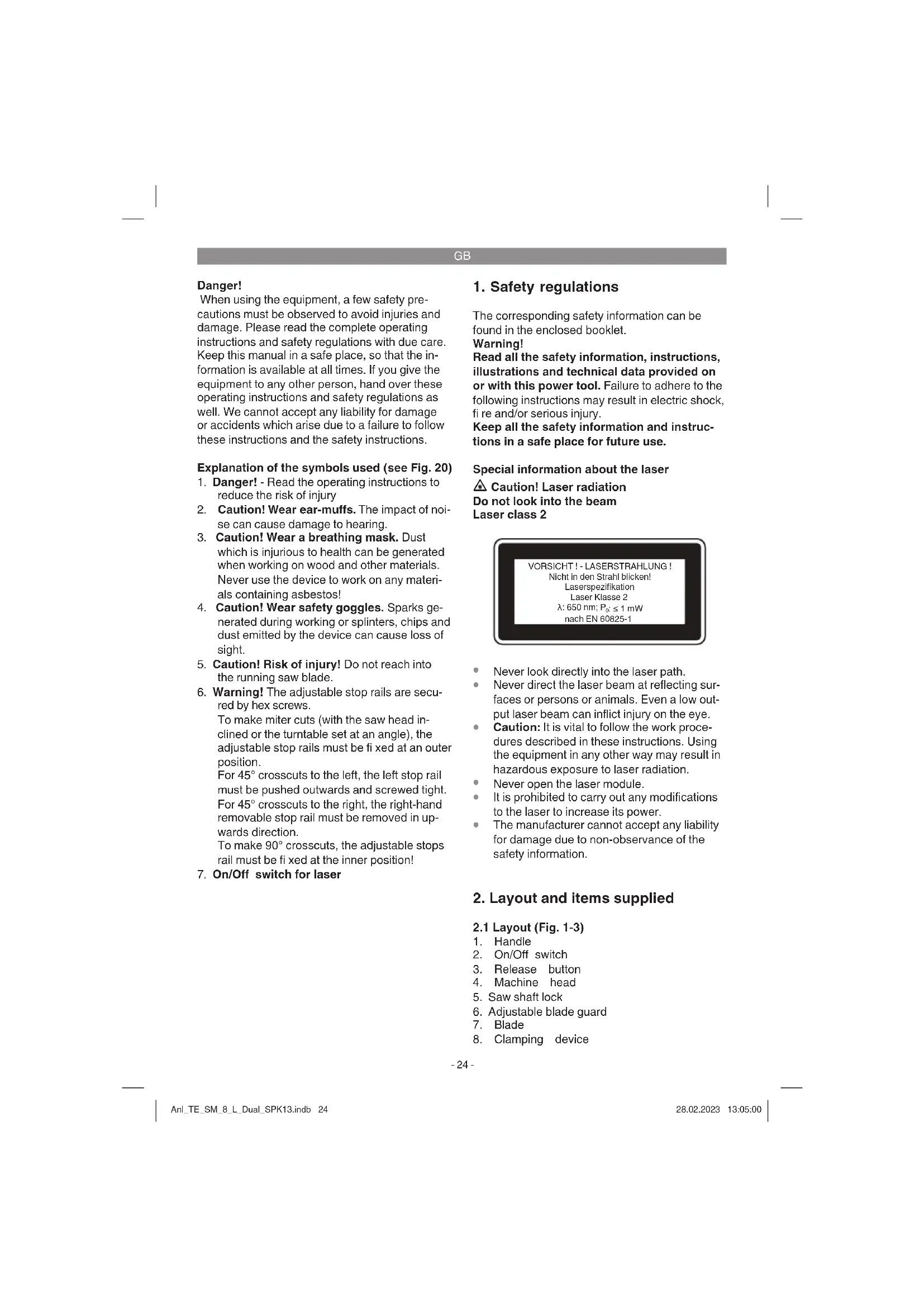
When using the equipment, a few safety precautions must be observed to avoid injuries and damage. Please read the complete operating instructions and safety regulations with due care. Keep this manual in a safe place, so that the information is available at all times. If you give the equipment to any other person, hand over these operating instructions and safety regulations as well. We cannot accept any liability for damage or accidents which arise due to a failure to follow these instructions and the safety instructions.
Explanation of the symbols used (see Fig. 20)
- Danger! - Read the operating instructions to reduce the risk of injury
- Caution! Wear ear-muffs. The impact of noise can cause damage to hearing.
- Caution! Wear a breathing mask. Dust which is injurious to health can be generated when working on wood and other materials. Never use the device to work on any materials containing asbestos!
- Caution! Wear safety goggles. Sparks generated during working or splinters, chips and dust emitted by the device can cause loss of sight.
- Caution! Risk of injury! Do not reach into the running saw blade.
- Warning! The adjustable stop rails are secured by hex screws. To make miter cuts (with the saw head inclined or the turntable set at an angle), the adjustable stop rails must be fixed at an outer position. For 45^ crosscuts to the left, the left stop rail must be pushed outwards and screwed tight. For 45^ crosscuts to the right, the right-hand removable stop rail must be removed in upwards direction. To make 90^ crosscuts, the adjustable stops rail must be fixed at the inner position!
- On/Off switch for laser
1. Safety regulations
The corresponding safety information can be found in the enclosed booklet.
Warning!
Read all the safety information, instructions, illustrations and technical data provided on or with this power tool. Failure to adhere to the following instructions may result in electric shock, fire and/or serious injury.
Keep all the safety information and instructions in a safe place for future use.
Special information about the laser
Caution! Laser radiation
Do not look into the beam
Laser class 2
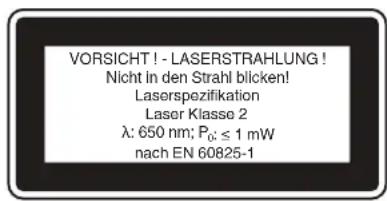
- Never look directly into the laser path.
- Never direct the laser beam at reflecting surfaces or persons or animals. Even a low output laser beam can inflict injury on the eye.
- Caution: It is vital to follow the work procedures described in these instructions. Using the equipment in any other way may result in hazardous exposure to laser radiation.
- Never open the laser module.
It is prohibited to carry out any modifications to the laser to increase its power.
The manufacturer cannot accept any liability for damage due to non-observance of the safety information.
2. Layout and items supplied
2.1 Layout (Fig. 1-3)
- Handle
- On/Off switch
- Release button
- Machine head
- Saw shaft lock
- Adjustable blade guard
- Blade
- Clamping device
GB
-
Release lever
-
Workpiece support
- Locking grip for workpiece support
- Screw for workpiece support
- Fixed stop rail
- Movable stop rail
- Locking grip for movable stop rail
- Table insert
- Adjustable foot
- Fixed saw table
- Turntable
- Locking lever (turntable)
- Unlock button
- Pointer (turntable)
- Scale (turntable)
- Pointer (miter)
- Scale (miter)
- Locking grip (miter)
- Sawdust bag
- Discharge opening
- Locking screw for drag guide
- Retaining pin
- Knurled screw for cutting depth limiter
- Lock nut for cutting depth limiter
- Stop plate for cutting depth limiter
- Screw for cutting depth limiter
- Adjustment screw for angle stop 90^
- Adjustment screw for angle stop 45^ left
- Lock nut for angle stop
- Flange bolt
- Outer flange
- Inner flange
- Laser
- On/Off switch for laser
- Guide for workpiece support
- Adjustment screw for stop rail
- 6mm hex key
- Socket head screw
- Adjustment screw for angle stop 45^ right
- Removable stop rail
2.2 Items supplied
Please check that the article is complete as specified in the scope of delivery. If parts are missing, please contact our service center or the sales outlet where you made your purchase at the latest within 5 working days after purchasing the product and upon presentation of a valid bill of purchase. Also, refer to the warranty table in the service information at the end of the operating instructions.
- Open the packaging and take out the equipment with care.
- Remove the packaging material and any packaging and/or transportation braces (if
available).
Check to see if all items are supplied.
- Inspect the equipment and accessories for transport damage.
If possible, please keep the packaging until the end of the guarantee period.
Danger!
The equipment and packaging material are not toys. Do not let children play with plastic bags, foils or small parts. There is a danger of swallowing or suffocating!
Drag, crosscut and miter saw
- Clampingdevice
Workpiece support (2x)
Locking grip for workpiece support (2x)
Screw for workpiece support (2x)
Sawdustbag
Guide for workpiece support (2x)
- 6mm hex key
- Removable stop rail
Original Operating Instructions
SafetyInformation
3. Proper use
The drag, crosscut and miter saw is designed for cross-cutting wood and wood-type materials which are appropriate for the machine's size. The saw is not designed for cutting fi rewood.
The equipment is to be used only for its prescribed purpose. Any other use is deemed to be a case of misuse. The user / operator and not the manufacturer will be liable for any damage or injuries of any kind caused as a result of this.
Please note that our equipment has not been designed for use in commercial, trade or industrial applications. Our warranty will be voided if the machine is used in commercial, trade or industrial businesses or for equivalent purposes.
The equipment is to be operated only with suitable saw blades. It is prohibited to use any type of cutting-off wheel.
To use the equipment properly you must also observe the safety information, the assembly instructions and the operating instructions to be found in this manual.
All persons who use and service the equipment
GB
have to be acquainted with these operating instructions and must be informed about the equipment's potential hazards. It is also imperative to observe the accident prevention regulations in force in your area. The same applies for the general rules of health and safety at work.
The manufacturer will not be liable for any changes made to the equipment nor for any damage resulting from such changes. Even when the equipment is used as prescribed it is still impossible to eliminate certain residual risk factors.
The following hazards may arise in connection with the machine's construction and design:
- Contact with the saw blade in the uncovered saw zone.
- Reaching into the running saw blade (cut injuries).
- Kick-back of workpieces and parts of workpieces.
Saw blade fracturing. - Catapulting of faulty carbide tips from the saw blade.
- Damage to hearing if essential ear-muffs are not used.
- Harmful emissions of wood dust when used in closed rooms.
4. Technical data
AC motor: 220-240 V ~ 50Hz
Power: 1500 W S1 / 1800 W S6 25%
Idle speed n_0 .. 5000 min
Carbide saw blade: 216 x 0 30 x 2.4 mm
Maximum tooth pitch 2.8 mm
Number of teeth: 48
Swiveling range: -47° / 0° / +47°
Miter cut to the left: 0^ to 45^
Miter cut to the right: 0^ to 45^
Saw width at 90^ .. 305 x 65 mm
Saw width at 45^ .. 215 x 65 mm
Saw width at 2 × 45^
(double miter cut, left): 215 x 35 mm
Saw width at 2 × 45^
(double miter cut, right): 215 x 20 mm
Weight: approx. 14 kg
Laser class: 2
Wavelength of laser: 650 nm
Laser output: ≤ 1mW
Protection class:
Minimum workpiece size: Only ever cut workpieces which are big enough to clamp securely with the clamping device - minimum length 160mm
Operating mode S6 25% :Continuous operation with idling (cycle time 10 minutes).To ensure that the motor does not become excessively hot, it may only be operated for 25% of the cycle at the specified rating and must then be allowed to idle for 75% of the cycle.
Danger!
Noise
The noise emission values were measured in accordance with EN 62841.
LpA sound pressure level 95.5 dB(A)
KBA uncertainty 3 dB(A)
L_WA sound power level 108.5 dB(A)
K_WA uncertainty 3 dB(A)
Wear ear-muff s.
The impact of noise can cause damage to hearing.
The stated noise emission values were measured in accordance with a set of standardized criteria and can be used to compare one power tool with another.
The stated noise emission values can also be used to make an initial assessment of exposure.
Warning:
The noise emission levels may vary from the level specified during actual use, depending on the way in which the power tool is used, especially the type of workpiece it is used for.
Keep the noise emissions and vibrations to a minimum.
Only use appliances which are in perfect working order.
Service and clean the appliance regularly.
Adapt your working style to suit the appliance.
- Do not overload the appliance.
- Have the appliance serviced whenever necessary.
- Switch the appliance off when it is not in use.
Caution!
Residual risks
Even if you use this electric power tool in accordance with instructions, certain resi
GB
dual risks cannot be rules out. The following hazards may arise in connection with the equipment's construction and layout:
- Lung damage if no suitable protective dust mask is used.
- Damage to hearing if no suitable ear protection is used.
- Health damage caused by hand-arm vibrations if the equipment is used over a prolonged period or is not properly guided and maintained.
5. Before starting the equipment
Before you connect the equipment to the mains supply make sure that the data on the rating plate are identical to the mains data.
Warning!
Always pull the power plug before making adjustments to the equipment.
5.1 General information
The equipment must be set up where it can stand securely, i.e. it should be bolted to a workbench, a universal base frame or similar.
- All covers and safety devices have to be properly fitted before the equipment is switched on.
It must be possible for the blade to run freely.
- When working with wood that has been processed before, watch out for foreign bodies such as nails or screws, etc.
Before you actuate the On/Off switch, make sure that the saw blade is correctly fitted and that the equipment's moving parts run smoothly.
5.2 Assembling the saw (Fig. 1-4)
- Thread the workpiece supports (10) onto the guides (43) (Fig. 4). Then fit the guides onto the fixed saw table (18) and fasten them with the screw (12). Use a crosstip screwdriver to do this.
The workpiece support (10) can be moved on the guide (43) to adjust it to the length of the workpiece you want to saw. Once the workpiece support (10) is in the right position, screw the locking grip (11) downwards so that it is in contact with the support surface. This is to prevent the saw tilting when you work on long or large workpieces.
To fit the sawdust bag (27) to the discharge opening (28) on the crosscut saw, spread the
metal ring apart on the opening. When the metal ring is back in its original shape, the sawdust bag is held securely in position.
The clamping device (8) can be fitted on the left or right of the fixed saw table (18).
A crosstip screwdriver is not supplied with the product.
Note: The 6mm hexagon key (45) for changing the saw blade should be kept on the back of the machine (see Fig. 17).
5.3 Adjusting the saw (Fig. 1-3,5)
To adjust the turntable (19), the locking lever (20) must be in the top position. Only then is it possible to adjust the turntable while holding the release button (21) pressed down. (see Fig. 5)
- Turn the turntable (19) and scale pointer (22) to the desired angular setting on the scale (23).
The saw has locking positions at angles of -45^, -30^, -22.5^, -15^, 0^, 15^, 22.5^, 30^ and 45^ , at which the turntable (19) audibly clicks into position. Once the turntable is engaged, the setting must be additionally secured by pressing the locking lever (20) down.
If different angle settings are required, the turntable (19) may be secured in position using only the locking lever (20).
To release the saw from its position at the bottom, pull the retaining pin (30) out of the motor mounting while pressing down lightly on the machine head (4).
- Swing up the machine head (4).
To adjust the machine head (4) for a miter cut, the locking grip (26) must be in the top position.
- Then you can tilt the machine head (4) to the left by up to 45^ . After the desired angular setting has been set on the scale pointer (24) on the scale (25), secure the machine head (4) again with the locking grip (26).
To tilt the machine head to the right by up to 45^ proceed as follows:
- Tilt the machine head (4) by approx. 10^ to the left.
- Press and hold the release lever (9).
- Swing the machine head (4) over the 0^ line to the right.
- After reaching approx. 10^ on the right-hand side, let go of the release lever (9).
- When the scale pointer (24) reaches the desired angular setting on the scale (25), secure the machine head (4) again with the
GB
locking grip (26).
To return the machine head to 0^ on the scale (25) there is no need to press the release lever (9) again.
To ensure that the saw is standing securely, adjust the adjustable foot (17) by turning it so that the saw stands in a horizontal and firm position.
The machine head (4) can be moved backwards and forwards using the drag function. To prevent the drag function, the guide rails can be fixed in a specific position with the locking screw (29).
5.4 Precision adjustment of the stop rail (Fig. 6, 7)
Lower the machine head (4) and fasten in place with the retaining pin (30).
- Fasten the turntable (19) in 0^ position.
- Place the 90^ stop angle (a) between the blade (7) and the stop rail (13).
- Slacken the four adjustment screws (44) using a hex key, set the stop rail (13) to 90^ in relation to the saw blade (7) and retighten the adjustment screws (44).
The angle stop (a) and hex key (5mm) are not included in the scope of this delivery.
5.5 Precision adjustment of the angle stop for crosscut 90^ (Fig. 8a, 9)
Lower the machine head (4) and fasten in place with the retaining pin (30).
- Fasten the turntable (19) in 0^ position.
- Undo the locking grip (26) and tilt the machine head (4) to 0^ using the handle (1).
- Place the 90^ angular stop (a) between the blade (7) and the turntable (19).
- Slacken the lock nut (37) and adjust the adjustment screw (35) until the angle between the blade (7) and the turntable (19) equals 90^ .
- Retighten the lock nut (37) to secure this setting.
- Finally, check the position of the pointer (24). If necessary, release the pointer with a cros-stip screwdriver, move to the 0^ position of the angle scale (25) and retighten the pointer.
The angle stop (a) and crosstip screwdriver are not included in the scope of this delivery.
5.6 Precision adjustment of the angle stop for 45^ miter cut to the left (Fig. 8b, 10a)
Lower the machine head (4) and fasten in place with the retaining pin (30).
- Fasten the turntable (19) in 0^ position.
- Undo the locking grip (26) and tilt the machine head (4) all the way to the left to 45^ using the handle (1).
- Place the 45^ stop angle (b) between the blade (7) and the turntable (19).
- Slacken the lock nut (37) and adjust the adjustment screw (36) until the angle between the blade (7) and the turntable (19) equals exactly 45^ .
- Retighten the lock nut to secure this setting.
No angle stop (b) included.
5.7 Precision adjustment of the angle stop for 45^ miter cut to the right (Fig. 8b, 10b)
Lower the machine head (4) and fasten in place with the retaining pin (30).
- Fasten the turntable (19) in 0^ position.
- Undo the locking grip (26) and tilt the machine head (4) all the way to the left to 45^ using the handle (1).
- Place the 45^ stop angle (b) between the blade (7) and the turntable (19).
- Slacken the lock nut (37) and adjust the adjustment screw (47) until the angle between the blade (7) and the turntable (19) equals exactly 45^ .
- Retighten the lock nut to secure this setting.
No angle stop (b) included.
6. Operation
Warning! To make 90^ crosscuts, the adjustable stop rail (14) must be fixed at the inner position:
- Undo the locking grip (15) for the adjustable stop rail and push the adjustable stop rail inwards.
- The adjustable stop rail (14) must be fixed far enough in front of the innermost position that the distance between the stop rail (14) and the saw blade (7) amounts to a maximum of 8mm .
Before making a cut, check that the stop rail and the saw blade cannot collide. - Tighten the locking grip (15) again.
Warning! To make 0^ - 45^ miter cuts to the left (with the machine head (4) inclined or with the turntable set at an angle), the adjustable stop rail (14) must be fixed at an outer position.
- Undo the locking grip (15) for the adjustable stop rail and push the adjustable stop rail outwards.
The adjustable stop rail (14) must be fixed far
GB
enough in front of the innermost position that the distance between the stop rail (14) and the saw blade (7) amounts to a maximum of 8mm.
Before making a cut, check that the stop rail and the saw blade cannot collide.
- Tighten the locking grip (15) again.
Warning! This saw is equipped with a removable stop rail (48) which is screwed to the fixed stop rail (13).
To make 0^ - 45^ miter cuts to the right (with the machine head (4) inclined or with the turntable set at an angle), the removable stop rail (48) must be completely removed. Warning! In this case the maximum permissible workpiece height is reduced (see 4. Technical data).
Use a hex key to open the socket head screw (46) of the removable stop rail (48) (see Fig. 19). Note: This product does not come with a 5mm hex key.
- Pull off the removable stop rail in upwards direction.
Always fasten the removable stop rail (48) on the equipment again after you have completed your work.
- The stop rail must always be kept together with the equipment. A removed stop rail will impair the operational safety of the equipment.
6.1 Cross cut 90^ and turntable 0^ (Fig. 1-3, 11)
For cutting widths up to approx. 100mm it is possible to fix the saw's drag function with the locking screw for drag guide (29) in rear position. If the cutting width exceeds 100mm you must ensure that the locking screw for drag guide (29) is slackened and that the machine head (4) can be moved.
- Move the machine head (4) to its upper position.
Use the handle (1) to push back the machine head (4) and fix it in this position if required (dependent on the cutting width). - Place the piece of wood to be cut at the stop rail (13) and on the turntable (19).
- Lock the material with the clamping device (8) on the fixed saw table (18) to prevent the material from moving during the cutting operation.
- Press the release button (3) to release the On/Off switch (2).
- Press the On/Off switch (2) to start the motor.
- With the drag guide fixed in place: Use the
handle (1) to move the machine head (4) steadily and with light pressure downwards until the saw blade (7) has completely cut through the workpiece.
- With the drag guide not fixed in place: Pull the machine head (4) all the way to the front and then use the handle (1) to move it downwards steadily and with light pressure. Now push the machine head (4) slowly and steadily to the very back until the saw blade (7) has completely cut through the workpiece.
- When the cutting operation is completed, move the machine head (4) back to its upper (home) position and release the On/Off button (2).
Important! The integral resetting springs will automatically lift the machine head. Do not simply let go of the handle (1) after cutting, but allow the machine head (4) to rise slowly, applying slight counter pressure as it does so.
6.2 Cross cut 90^ and turntable 0^ - 45^ (Fig.1-3,12)
The crosscut saw can be used to make crosscuts of 0^ - 45^ to the left and 0^ - 45^ to the right in relation to the stop rail.
- Swing up the machine head (4).
- Move the locking lever (20) to its top position to enable the turntable to be adjusted.
While holding the release button (21) pressed down, turn the turntable (19) and scale pointer (22) to the desired angular setting on the scale (23).
To lock the turntable (19), press the locking lever (20) down.
Cut as described in section 6.1.
6.3 Miter cut 0^ - 45^ and turntable 0^ (Fig. 1-3, 13)
The crosscut saw can be used to make miter cuts to the left of 0^ - 45^ and to the right of 0^ - 45^ in relation to the work surface.
If required, dismantle the clamping device (8) or mount it on the opposite side of the fixed saw table (18).
- Move the machine head (4) to its upper position.
- Fasten the turntable (19) in 0^ position.
- Move the locking grip (26) to its upper position.
For a miter angle to the left: Tilt the machine head (4) to the left until it coincides with the required angular setting of the scale pointer (24) on the scale (25).
For a miter angle to the right: Tilt the machine
GB
head (4) approx. 10^ to the left, press and hold the release lever (9), swing the machine head (4) over the 0^ line to the right, after approx. 10^ let go of the release lever (9), tilt the machine head (4) to the right until it coincides with the required angular setting of the pointer (24) on the scale (25).
Then secure the locking grip (26) again.
Cut as described in section 6.1.
6.4 Miter cut 0^ - 45^ and turntable 0^ - 45^ (Fig. 1-3, 14)
The crosscut saw can be used to make miter cuts to the left of 0^ - 45^ and to the right of 0^ - 45^ in relation to the work surface, with simultaneous setting of the turntable from 0^ - 45^ to the left or 0^ - 45^ to the right in relation to the stop rail (double miter cut).
If required, dismantle the clamping device (8) or mount it on the opposite side of the fixed saw table (18).
- Move the machine head (4) to its upper position.
- Move the locking lever (20) to its top position to enable the turntable to be adjusted.
While holding the release button (21) pressed down, turn the turntable (19) and scale pointer (22) to the desired angular setting on the scale (23).
To lock the turntable (19), press the locking lever (20) down.
- Move the locking grip (26) to its upper position.
For a miter angle to the left: Tilt the machine head (4) to the left until it coincides with the required angular setting of the scale pointer (24) on the scale (25).
For a miter angle to the right: Tilt the machine head (4) approx. 10^ to the left, press and hold the release lever (9), swing the machine head (4) over the 0^ line to the right, after approx. 10^ let go of the release lever (9), tilt the machine head (4) to the right until it coincides with the required angular setting of the pointer (24) on the scale (25).
Then secure the locking grip (26) again.
Cut as described in section 6.1.
6.5 Limiting the cutting depth (Fig. 15)
The cutting depth limiter can be activated with the help of the screw (34).
To do so, slacken the screw (34) using a cros-stip screwdriver, so that the stop plate can be moved. Then move the stop plate (33) as far as possible towards the saw blade and retigh
ten the screw (34) afterwards.
The cutting depth can be infinitely adjusted using the knurled screw (31). To do so, slacken the lock nut (32) and set the required cutting depth by turning the knurled screw (31) in or out. Then retighten the lock nut (32) on the screw (31).
- Check the setting by completing a test cut.
A crosstip screwdriver is not supplied with the product.
6.6 Sawdust bag (Fig. 2)
The saw is equipped with a sawdust bag (27) for sawdust and chips.
The sawdust bag (27) can be emptied by means of a zipper at the bottom.
6.7 Replacing the saw blade (Fig. 1, 16)
Before changing the saw blade: Pull out the power plug!
- Wear work gloves to prevent injury when changing the saw blade.
- Swing the machine head upwards (4).
- Press the saw shaft lock (5) with one hand while positioning the hexagon key (45) on the flange bolt (38) with the other hand. The saw shaft lock (5) engages after no more than one rotation.
Now, using a little more force, slacken the flange screw (38) in the clockwise direction.
- Turn the flange screw (38) right out and remove the external flange (39).
Take the blade (7) off the inner flange (40) and pull out downwards. To do so, move the saw blade guard (6) upwards to enable access to the saw blade.
- Carefully clean the flange screw (38), outer flange (39) and inner flange (40).
- Fit and fasten the new saw blade (7) in reverse order.
- Important! The cutting angle of the teeth, in other words the direction of rotation of the saw blade (7) must coincide with the direction of the arrow on the housing.
- Check to make sure that all safety devices are properly mounted and in good working condition before you begin working with the saw again.
- Warning! Every time that you change the saw blade, check that the saw blade guard (6) opens and closes again in accordance with requirements. Also check that the saw blade (7) spins freely in the saw blade guard (6).
- Warning! Every time that you change the
GB
saw blade, check to see that it spins freely in the table insert (16) in both perpendicular and 45^ angle settings.
- Warning! You should replace the table insert (16) immediately whenever it is worn or damaged. To do so, undo the Philips screws in the table insert (16) and take the table insert out of the fixed saw table (18). To fit the new table insert (16), proceed in reverse order.
- Warning! The work to change and align the saw blade (7) must be carried out correctly.
6.8 Transport (Fig. 1-3)
- Press down the locking lever (20) to lock the turntable (19).
Using the scale (25), make sure that the angle for miter cuts is 90^ . In addition, the machine head (4) must be secured with the locking grip (26). - Press the machine head (4) downwards and secure with the retaining pin (30). The saw is now locked in its bottom position.
Fix the saw's drag function with the locking screw for drag guide (29) in rear position. - Carry the equipment by the fixed saw table (18).
To set up the equipment again, proceed as described in section 5.3.
6.9 Operating the laser (Fig. 1, 18)
Switching on: Move the On/Off switch (42) to the
" position to switch on the laser (41). A laser line is projected onto the material you wish to process, providing an exact guide for the cut.
Switching off: Move the On/Off switch (42) to the "OFF" position.
7. Replacing the power cable
Danger!
If the power cable for this equipment is damaged, it must be replaced by the manufacturer or its after-sales service or similarly trained personnel to avoid danger.
8. Cleaning, maintenance and ordering of spare parts
Danger!
Always pull out the mains power plug before starting any cleaning work.
8.1 Cleaning
- Keep all safety devices, air vents and the motor housing free of dirt and dust as far as possible. Wipe the equipment with a clean cloth or blow it with compressed air at low pressure.
We recommend that you clean the device immediately each time you have finished using it.
Clean the equipment regularly with a moist cloth and some soft soap. Do not use cleaning agents or solvents; these could attack the plastic parts of the equipment. Ensure that no water can seep into the device. The ingress of water into an electric tool increases the risk of an electric shock.
8.2 Carbon brushes
In case of excessive sparking, have the carbon brushes checked only by a qualifi ed electrician. Danger! The carbon brushes should not be replaced by anyone but a qualifi ed electrician.
8.3 Maintenance
There are no parts inside the equipment which require additional maintenance.
8.4 Ordering spare parts and accessories
Please provide the following information when ordering spare parts:
Type of unit
Article number of the unit
ID number of the unit
- Spare part number of the required spare part
For our latest prices and information please go to www.Einhell-Service.com

Tip! For good results we recommend high-quality accessories from www.kwb.eu welcome@kwb.eu
GB
9. Disposal and recycling
The equipment is supplied in packaging to prevent it from being damaged in transit. The raw materials in this packaging can be reused or recycled. The equipment and its accessories are made of various types of material, such as metal and plastic. Never place defective equipment in your household refuse. The equipment should be taken to a suitable collection center for proper disposal. If you do not know the whereabouts of such a collection point, you should ask in your local council offices.
10. Storage
Store the equipment and accessories in a dark and dry place at above freezing temperature. The ideal storage temperature is between 5 and 30^ . Store the electric tool in its original packaging.
GB

For EU countries only
Never place any electric power tools in your household refuse.
To comply with European Directive 2012/19/EC concerning old electric and electronic equipment and its implementation in national laws, old electric power tools have to be separated from other waste and disposed of in an environment-friendly fashion, e.g. by taking to a recycling depot.
Recycling alternative to the return request:
As an alternative to returning the equipment to the manufacturer, the owner of the electrical equipment must make sure that the equipment is properly disposed of if he no longer wants to keep the equipment. The old equipment can be returned to a suitable collection point that will dispose of the equipment in accordance with the national recycling and waste disposal regulations. This does not apply to any accessories or aids without electrical components supplied with the old equipment.
Please note that batteries and lamps (e.g. light bulbs) must be removed from the tool before it is disposed of.
The reprinting or reproduction by any other means, in whole or in part, of documentation and papers accompanying products is permitted only with the express consent of the Einhell Germany AG.
Subject to technical changes
The product meets the requirements of EN 61000-3-11 and is subject to special connection conditions. This means that use of the product at any freely selectable connection point is not allowed.
- Given unfavorable conditions in the power supply the product can cause the voltage to fluctuate temporarily.
The product is intended solely for use at connection points that a) do not exceed a maximum permitted mains system impedance of Z sys = 0.25 + j0.25 , or b) have a continuous current-carrying capacity of the mains of at least 100 A per phase.
- As the user, you are required to ensure, in consultation with your electric power company if necessary, that the connection point at which you wish to operate the product meets one of the two requirements, a) or b), named above.
GB
Service information
We have competent service partners in all countries named on the guarantee certificate whose contact details can also be found on the guarantee certificate. These partners will help you with all service requests such as repairs, spare and wearing part orders or the purchase of consumables.
Please note that the following parts of this product are subject to normal or natural wear and that the following parts are therefore also required for use as consumables.
| Category Example | |
| Wear parts* Carbon brushes | |
| Consumables* Saw blade | |
| Missing parts |
- Not necessarily included in the scope of delivery!
In the effect of defects or faults, please register the problem on the internet at www.Einhell-Service.com. Please ensure that you provide a precise description of the problem and answer the following questions in all cases:
Did the equipment work at all or was it defective from the beginning?
Did you notice anything (symptom or defect) prior to the failure?
What malfunction does the equipment have in your opinion (main symptom)?
Describe this malfunction.
GB
Warranty certificate
Dear Customer,
All of our products undergo strict quality checks to ensure that they reach you in perfect condition. In the unlikely event that your device develops a fault, please contact our service department at the address shown on this guarantee card. You can also contact us by telephone using the service number shown. Please note the following terms under which guarantee claims can be made:
- These guarantee terms apply to consumers only, i.e. natural persons intending to use this product neither for their commercial activities nor for any other self-employed activities. These warranty terms regulate additional warranty services, which the manufacturer mentioned below promises to buyers of its new products in addition to their statutory rights of guarantee. Your statutory guarantee claims are not affected by this guarantee. Our guarantee is free of charge to you.
- The warranty services cover only defects due to material or manufacturing faults on a product which you have bought from the manufacturer mentioned below and are limited to either the rectification of said defects on the product or the replacement of the product, whichever we prefer. Please note that our devices are not designed for use in commercial, trade or professional applications. A guarantee contract will not be created if the device has been used by commercial, trade or industrial business or has been exposed to similar stresses during the guarantee period.
-
The following are not covered by our guarantee:
-
Damage to the device caused by a failure to follow the assembly instructions or due to incorrect installation, a failure to follow the operating instructions (for example connecting it to an incorrect mains voltage or current type) or a failure to follow the maintenance and safety instructions or by exposing the device to abnormal environmental conditions or by lack of care and maintenance.
- Damage to the device caused by abuse or incorrect use (for example overloading the device or the use or unapproved tools or accessories), ingress of foreign bodies into the device (such as sand, stones or dust, transport damage), the use of force or damage caused by external forces (for example by dropping it).
-
Damage to the device or parts of the device caused by normal or natural wear or tear or by normal use of the device.
-
The guarantee is valid for a period of 24 months starting from the purchase date of the device. Guarantee claims should be submitted before the end of the guarantee period within two weeks of the defect being noticed. No guarantee claims will be accepted after the end of the guarantee period. The original guarantee period remains applicable to the device even if repairs are carried out or parts are replaced. In such cases, the work performed or parts fitted will not result in an extension of the guarantee period, and no new guarantee will become active for the work performed or parts fitted. This also applies if an on-site service is used.
-
To make a claim under the guarantee, please register the defective device at: www.Einhell-Service.com. Please keep your bill of purchase or other proof of purchase for the new device. Devices that are returned without proof of purchase or without a rating plate shall not be covered by the guarantee, because appropriate identification will not be possible. If the defect is covered by our guarantee, then the item in question will either be repaired immediately and returned to you or we will send you a new replacement.
Of course, we are also happy offer a chargeable repair service for any defects which are not covered by the scope of this guarantee or for units which are no longer covered. To take advantage of this service, please send the device to our service address.
Also refer to the restrictions of this warranty concerning wear parts, consumables and missing parts as set out in the service information in these operating instructions.
F
Danger!
Chere cliente, cher client,
6.6 Spanpose (fig. 2)
6.8 Transport (obr. 1-3)
6.8 Transport (obr. 1-3)
Vermogen laser: 1 mW
Beschermklasse: 1/1
6.8 Transport (afb. 1-3)
Negotovost K. 3 dB(A)
Nivo zvoene moi Lwa. 108,5dB(A)
Negotovost K_WA 3 dB(A)
Uporablajte zašcito za ušesa.
6.8 Transport (sl. 1-3)
- Pritrdilini vzvod (20) potisnite navzdol, da vrtljivo mizo (19) zaklenete.
S skalo (25) zagotovite, da je kot za zajeralne reze 90^ . Poleg tega mora biti glava stroja (4) prisrijena s prisrdilno rocico prisrdilno rocico (26). - Glavo stroja (4) potisnite navzdol in blokirajte z varnostnim zaticem (30). Žaga je zaklenjena v spodnjem položaju.
Vlechno fungckojo zage fiksiraje s pritrdilnim vijakom za vlechno vodenje (29) v zadnjem položaju.
Stroj prenašajte le na fiksirani mizi zaŽago (18). - Za ponovno montažo stroja ravnajte v skladu s točko 5.3.
SLO
6.9 Delovanje laserja (slika 1, 18)
Vklop: Stikalo za vklop/izklop laserja (42) pre-maknite v položaj » * «, da vklopite laser (41).
Lungimea undei laser: 650 nm
Putere laser: ≤ 1mW
Stimata clienta, stimate client,
produsele noastre sunt supuse unui control de calitate riguros. Daca totusi vredata acest aparat nu va fonctiona ireprosabil, ne pare foarte rau si va rugam sa va adresa t centrului nostru service, la adresa indica la finalul acestui certificat de garantie. Bineinteles ca va stam si la Telefon cu placere la dispositione, la numeroile de service mentionate. Pentru revendicarea pretentiilor de garantie trebuie tinut cont de urmatoarele:
6.5'Opio 8aoouc kmtc (EK.15)
To ouotma opiou baouc konnc mtopei va evpyoiothei me nV bisa (34).
Aaokapete Tn Bida (34) 1e eva staupokatoaibio, EtaoTne Tn Akaobnyosva mopei va kiveita. Karotiv KivnoTe Tnv NtAokaoyo (33) 0oo yivetau npoc nTv kateuuvon Tou diakou Tou npioviu kalenaov
MTopeite va puOioTe To boc Konnc aiaaBauTgue Tn Bida (31).IaToV aokanto auto laokapete Tnv Bida aosfaeiaac (32) KaipuOuicTe To eiuuouveo boc Konnc biWovTAC n EbiWovTAC Tn Bida (31).Katoiv Eaavoiyetye To naiadla aphialeiac (32) stn Bida (31).
EAEyEe Tn puOuon uE doKiaoTkn kon.
To otaupokataoβio (δev oumpapadετa.)
6.6 akocoulloynicpokaviidiwv (Eik.2)
To npovivival Eonlaouevo e oako yia m oulambdaowtwovokaviwv (27).
O akoosouooyic twpokaviow (27) mnoei va aoeiaotel ano to eepouap otnv katw nεupá.
GR
6.7 Avtikataoan Tou npiovodiaokou (Eikova 1, 16)
Piv TnV aalayh tou npiovodikou: ByaTe to Bua ouvdeonc e To diktuo ano Tnv npica!
Poc aonouyn Tpaunatuaowv va opate kata tnv aaayn tnc npiovoaac npoataeutika yavtia!
- IepiotpEeTc TnV KepaA nTnc mXavnC (4) npoc ta naW.
Me To eva xepi piote TnV payn Tou aEova Tou npioviou (5) kai me to alno xepi tooetne To kAesi dl AAEV (45) 0tn Biia TNC PhavTac (38).Meta ano maImuu mia oToPOh KOUmWveI n payn Tou aEova (5).
Me liyn nepioootepn duvamn xaalapwveTe Twpa dEiooTpopa tn biia mC phavtcac (38).
- Eβδωτε ηβδα φλντίας (38) τελειως προς τα εξω και αφαμεόσετην εξωτερική φλντία (39).
Apaepote Tny npiovojma (7) ano Tnv eawepkn favTc (40) kai tpaBnEe Tnpoc ta katw. Ta tov oKoTo ao KivnoTne Tny npoostaia Tou idkou Tou pioiov (6) npoc ta enaww wote va evai npooBaoiou
Kaθapiote npooektuKa Tny Biδa φλavTca (38), Tny EeWTepkn φλavTca (39) KAI TNY eOwTepkn φλavTca (40).
Tooetntote tv vdo biokto tou npovu (7) 0ynavIoTpoN oipka kalphiTe tv.
Ppoooxn! H loE nIeupa konnc twv Sovtiwv, 7n. n KATEUoVn Tepiortpoocn Tou dakou Tou npiovu (7), npene va ouuovc me tvkateuvoan tou belaou navw oTo npipBna.
IpoTu apxioTe nai va epyaTee to npiovi,va eEyEeTe Tny aeitoupyikotnTa twv ouotmuTsw aoaiaic.
PnpoEioon! Meta ano kaOe avtikataotaondeltaou va eayxeteav n npootaia toudeltaok (6) avoiye kai kkeiveu oouva Tc npodiyapacEs. EKTOC autou va eayxeteav odeltaoc (7) kveita euethetapa otyn npootaiadeltaok (6).
PpOeIbOIOIn! Na eEyxTe M Ta ano KaE aAayn Tou npiovobiaokou, ev KVEitau EeuBepa o npiovobiaKoc OE KAten Thean KaWc Ka uE KIAIg 45° OTov nayko (16).
PnoEioonn! Pnei aoewc vaavtkataotathetaiaaepuevn 1 eAattwpatikn thonaykou epyaaic (16). AovleTc n taupoibiec stn thean yia to KATEpyaOevo avtkeieo oTov npkyo epyaiaC (16) kai aapoeote tn thean yia to
KATEpyafoevoavtkeiuevoantovpayko epyaiaac(18).TOnotheTnoteeavtioptpo n oipa tn vea eon yia to KATEpyafoevo avtkeiuevo stov npayko epyaiaac (16).
PpOeIsDOnoiqn! Haalayn kai Evuypaun Tou pioovodokou (7) npenei vaekTeEoTei ootda.
Evnpewon yia to eepic
5. Pre puštanja u pigeon
Pre prikljucivanja proverite da li podaci na tablici s oznakom tipa odgovaraju podacima o mrezi. Upozorenje!
Pre Ngo sto pocnete da podesavate uredaj, uvek izvucite mrezni utika.
5.1 Opste
Mašinu morate da postavite stabilno, što znači učvrstite na radni sto, univerzalno postolje ili slično.
Pre pušanja u rad morate da montirate svePoklopce i sigurnosne uredaje.
List testere mora se slobodno kretati.
Kod drveta koje je već obradivano voditi računa o stranim telima, kao što su npr. ekseri ili zavrtnj itd.
- Pre aktiviranja prekidača za uključivanje / isključivanje proverite je li list testere pravilno montiran i krecu li se lakoPokretni delovi.
5.2 Montaza testere (sika 1-4)
Navucite podloge radnog predmeta (10) na vodice (43) (slika 4).Zatim montiraje vodicine na fiksni sto testere (18) i fiksiraje in zavrtnjima (12).Pri tom koristite krstasti odvijač.
- Podlogu radnog predmeta (10) mozete da pomerate na vodici (43) zavisno od dužine radnog predmeta. Kad se podloga radnog predmeta (10) nade u tacnoj poziciji, ručka za fiksiranje (11) se zavrne prema dole takao da dodiruje povrsinu podloge. To sprečava prevr-tanje testere kod dužih odnosno vecih radnih predmeta.
- Kesa za sakupljanje piljevine (27) stavlja se na izlazni otvor (28) testere za prorezivanje takoto sto se metalini prsten rasiri na otvoru. Kesa za sakupljanje piljevine moze bezbedno da se montira ukoliko je metalini prsten u početnom stanju.
- Mechanizam za stezanje (8) moze da se montira i levo i desno na fiksni sto testere (18).
- Krystastiodvijač se ne nalazi u obimu isporuke.
Napomena: Imbus ključ 6 mm (45) za zamenu lista testere treba Čuvati na zadnjoj strani mašine (vidi sl. 17).
5.3 Podesavanje testere (sika 1-3, 5)
Za podesavanje obrtnog stola (19) poluga za fiksiranje (20) se mora nalaziti u posve gornjem polozaju. Tek nakon toga mozte da podesite obrtni sto, drzeci pritsnutim taster za deblokadu (21). (vidi sl. 5)
- Obrtni sto (19) i kazaljku (22) obrnite na zejlenu ugaonu meru skale (23).
Testera poseduje položaje fiksiranja na pozicijama -45^ -30^ -22,5^ -15^ 0^ 15^ 22,5^ 30^ i 45^ u kojima obrnsto (19) moze Čujno da se uglavi na mesto. Čim se obrnsto utvrdi, položaj mora dodatno da se fiksira pri-tiskom poluge za fiksiranje (20) prema dole.
Ako bi bili potrebni i drugi ugaoni polozaji, obrtni sto (19) fiksiraje samo pomocu poluge za fiksiranje (20).
Laganim pritiskom na glavu masine (4) prema dole i istodobnim izvlaenjem sigurnosnog klna (30) iz drzača motora, testera se deblokira iz donjeg položaja.
Glavu masine (4) zakrenite prema gore.
- Za podešavanje glave masine (4) za ugaoni rez ručka za fiksiranje (26) se mora nalaziti u gornjem položaju.
Glava masine (4) sada moze magnuti ulevo na maks. 45^ . Nakon postizanja zejenog ugla kazaljke (24) na skali (25), ponovno fiksirajte glavu masine (4) odgovarajućom ručkom (26).
Da bi se glava masine mogla nagnuti udesno na maks. 45^ postupite na sledeci nacin:
- Nagnite glavu masine (4) ulevo za oko 10^ .
- Pritisnite polugu za deblokiranje (9) i držite je pritisnutom.
- Glavu masine (4) zakrenite udesno iznad linje od 0^ .
- Nakon oko 10^ na desnoj strani, otpustite polugu za deblokiranje (9).
- Nakon postizanja zeiljenog ugra kazaljke (24) na skali (25), ponovno fi ksiraje glavu masine (4) odgovarajućom ručkom (26).
Da biste ponovno podesili glavu masine na 0^ na skali (25), nije vishe potrebno da pritiskate polugu za deblokiranje (9).
Da bi se zagarantovao bezbedan položaj testere, korigujte nogar (17) takdougo dok testera ne bude horizontalna i stabilna.
- Glavu masine (4) mozte da pomerate na-pred i nazad pomocu funkcie povlacenja.
RS
Da bistene onemogucili funkciju povlacenja, zavrtnjem (29) mozete da fiksirate vodice u odgovarajućem položaju.
5.4 Fino podesavanje granicne vodicice (sl. 6, 7)
Spustite glavu mašine (4) i fiksirajte je sigur-nosnim klinom (30).
Fiksirajte obrtni sto (19) u položaju 0^ .
Postavite ugaoni granicnik od 90^ (a) izmedulista testere (7) i granicne vodice (13).
Olabavitecetiri zavrtnja za podesavanje (44) imbus kljucem, granicu vodicu (13) postavite pod uglom od 90^ na list testere (7) i ponomno stegmite zavrtnje za podesavanje (44).
Ugaoni graničnik (a) i imbus ključ od 5 mm nisu sadrzani u isporuci.
5.5 Fino podesavanje ugaonog graničnika za prorezivanje pod 90^ (sl. 8a, 9)
Spustite glavu masine (4) i fiksirajte je sigur-nosnim klinom (30).
Fiksiraje obrtni sto (19) u položaju 0^
Olabavite ručku za fiksiranje (26) i pomocu ručke (1) nagnite glavu masine (4) na 0^ .
Postavite ugaoni granicnik od 90^ (a) izmedulista testere (7) i obrnog stola (19).
- Olabavite kontranavrtku (37) i podesavajte zavrtanj (35) sve dok ugao izmedu lista testere (7) i obrtnog stola (19) ne bude 90^ .
Da biste taj položaj fiksirali, ponovo stegnite kontranavrtku (37).
Na kraju proverite poziciju kazaljke (24). Ako je potrebno, krstastim odvijačem olabavite kazaljku, postavite skalu ugla (25) na položaj 0^ i ponovn stegnite kazaljku.
Ugaoni granicnik (a) i krstasti odvijač nisu sadrzani u obimu isporuke.
5.6 Fino podesavanje ugaonog granicnika za ugaoni rez pod 45^ ulevo (slika 8b, 10a)
Spustite glavu mašine (4) i fiksirajte je sigur-nosnim klinom (30).
Fiksiraje obrtni sto (19) u položaju 0^
Olabavite ručku za fiksiranje (26) i pomocu ručke (1) nagnite glavu masine (4) ulevo pod uglom od 45^ .
Postavite ugaoni granicnik od 45^ (b) izmedu lista testere (7) i obrnog stola (19).
- Olabavite kontranavrtku (37) i podesavajte zavrtanj za podesavanje (36) sve dok ugao izmedu lista testere (7) i obrtog stola (19) ne bude iznosio tačno 45^ .
- Za fiksiranje ovog podesavanja ponovo steg-nite kontranavrtku.
Ugaonigranicnik (b) ne dobija se u isporuci.
5.7 Fino podesavanje ugaonog granicnika za ugaoni rez pod 45^ udesno (slika 8b, 10b)
Spustite glavu masine (4) i fiksiraje je sigurnosnim klinom (30).
Fiksirajte obrtni sto (19) u poLOZaju 0^
Olabavite ručka za fiksiranje (26) i pomoću ručke (1) nagnite glavu mašine (4) udesno pod uglim od 45^ (vidi 5.3).
Postavite ugaoni granichnik od 45^ (b) izmedulista testere (7) i obrtnog stola (19).
- Olabavite kontranavrtku (37) i podesavajte zavrtanj za podesavanje (47) sve dok ugao izmedu lista testere (7) i obrtog stola (19) ne bude iznosio tacho 45^ .
- Za fiksiranje ovog podesavanja ponovo stegnite kontranavrtku.
Ugaonigranicnik (b) ne dobija se u isporcuci.
6. Rad
Upozorenje! Za prorezivanje pod 90^ pokretna granična vodica (14) mora se fiksirati unutrasnjoj poziciji.
- Odvrniteručku za fiksiranje (15)Pokretne granične vodice i gurnite vodicu prema unutra.
- Pokretnu granicnu vodicu (14) morate da utvrdite pre krajnje unutrašnje pozicije toliko da razmak izmedu granicne vodicie (14) i lista testere (7) iznosi maksimalno 8 mm.
- Pre rezanja proverite da li je moguçé da dode do kolizije izmedu grančne vodice i lista testere.
- Ponovno stegnite ručka za fiksiranje (15).
Upozorenje! Pokretnu granichnu vodicu (14) morate da u svru izvodenja kosih rezova ulevo pod 0^ - 45^ (uz nagnutlu glavu masine (4) ili nagnut obrtni sto s podesavanjem ugla) fi ksirate u spojnoj poziciji:
- Odvrniteručku za fiksiranje (15)Pokretne granicne vodice i gurnite vodicu prema spoja.
- Pokretnu granicnu vodicu (14) morate da utvrdite pre krajnje unutrasnje pozicije tolko da razmak izmedu granicne vodicse (14) i lista testere (7) iznosi maksimalno 8 mm.
- Pre rezanja proverite da li je moguce da dode do kolizije izmedu granicne vodice i lista testere.
- Ponovno stegnite ručku za fiksiranje (15).
RS
6.8 Transport (sika 1-3)
- Pritisnite polugu za fiksiranje (20) prema doletako da blokirate obrtni sto (19).
- Pomocu shale (25) proverite da li ugao za koso rezanje iznosi 90^ . Sem toga, glavu masine (4) morate da fiksirate odgovarajucom ručkom (26).
Glavu masine (4) pritisnite prema dole i fiksiraje pomocu sigurnosnog klna (30). Testera je sad blokirana u donjem poLOZaju. - Pomocu zavrtnja za fiksiranje za vodice za povlacenje (29) fiksiraje funkciju povlacenja testere u zadnjem položaju.
- Masinu nosite drzejci je za fiksni sto testere (18).
Da biste ponovno montirali masinu, postupite prema tacki 5.3.
6.9 Rad lasera (slika 1, 18)
Ukljucivanje: Da biste ukljucili laser (41), pomerite prekidača za ukljucivanje/iskljucivanje lasera (42) u položaj. Na radni predmet koji obradujete projcira se laserka linija kojaPokazuje tačnu poziciju vodice rezanja.
6.8 Transport (rys. 1-3)
6.8 Transport (Sekil 1-3)
6.6 Saepurukott (Joonis 2)
6.8 Transportimine (joonised 1-3)
区2006/42/EC
Annex IV Notifi ed Body: Reg.No.:
2000/14/EC_2005/88/EC
Annex V
Annex VI
Noise: measured Lwa = dB (A); guaranteed Lwa = dB (A) P = kW; L/0 = cm
Notified Body:
2012/46/EU. (EU)2016/1628 Emission No.:
Standard references: EN 62841-1; EN IEC 62841-3-9; EN 60825-1; EN IEC 55014-1; EN IEC 55014-2; EN IEC 61000-3-2; EN IEC 61000-3-11
Subject to change without notice
Archive-File/Record: NAPR024379 Documents registrar: Korbinian Wasmeier Wiesenweg 22, D-94405 Landau/slar
1 BG Drg, croscut and miter sew - F Bole ang radiale - J Saga a trazione per frontale e aggel abillio - DKW Skov - kap- og gergnes - 5 Drag , kap- og gergnes - Cz Kauwola o pokosova pla o podzadn - SK Tsekova, kapaovsia o povozna pla - Nk, aketik - an sterevskie - E Slora de troconon, oscilias y parer cortingas - P VVtlo - karkaska - Ja Iritsna - SLo Dvostra zhe, zolna ziga in zagomina zago - H Vond, tejoc - es karko kultko - RO Herkova jogur, do rezerit i imarim loi t - GR GcIorcompoe kai npov cydov kornki - Rr. Se of tropa, corte transversal a mea esquacion - NR WfR GbU kuzma kula nza prozvezniye - RS Kupu kuzma lestiera prezverizne - K zo rozane - Pr. Akhna - TR Gyne lesme - RUS Ipontemaeus rupceus uycyepenam - EE Nega - ja karmekas - LV Skovzglis, esperandinas zajuklenje - LT Kombunoslavace tempezmije [Zambe paesareni kligas - BG Lrgovnoi sa rasa ne konnyanemcpes 0ctatrnare da cotoe hcnotrae - NK Urochyn - NK Urochyn - NK Urochyn - NK Urochyn - NK Urochyn - NK Urochyn - NK Urochyn - NK Urochyn

Declaration of conformity
We, Einhell UK Ltd
Champions Business Park, First Floor Unit 10, Arrowe Brook Rd, Upton, Wirral CH49 0AB, United Kingdom
declare the conformity to UK standards and legislation was assessed for:
Sliding Mitre Saw TE-SM 8 L Dual (Einhell)
UK legislation
Simple Pressure Vessels (Safety) Regulation
Electrical Equipment (Safety) Regulation
Radio Equipment Regulation
Personal Protective Equipment Regulation
The Ecodesign for Energy-Related Products and Energy Information Regulation
The Restriction of the Use of Certain Hazardous Substances in Electrical and Electronic Equipment Regulation
Nolse Emisslon in the Environment by Equipment for use Outdoors Regulation
Annex V
Annex VI
Noise:measuredL = dB A):guaranteed L_w = dB A
P = kW; L/0 = cm
UK Approved Body:
Supply of Machinery (Safety) Regulation
Annex IV
UK Approved Body:
UKTE Certificat No.:
Standard references: BS EN 62841-1; BS EN IEC 62841-3-9; BS EN 60825-1; BS EN IEC 55014-1; BS EN IEC 55014-2; BS EN IEC 61000-3-2; BS EN IEC 61000-3-11
Wirral, 2023.02.22

Article Number:43.008.66 I-No.:21010
Subject to change without notice Wiesenweg 22, 94405 Landau/Isar, Germany
Archive-File/Record: NAPR024379
Documents registrar: Korbinian Wasmeier
EH 02/2023 (01)