
TE-MB 18/127 U Li - Electric saw EINHELL - Free user manual and instructions
Find the device manual for free TE-MB 18/127 U Li EINHELL in PDF.
| Product Type | Cordless Band Saw |
| Brand | Einhell |
| Model | TE-MB 18/127 U Li |
| Power Supply | 18 V lithium-ion battery (not included) |
| No-load rotation speed | 240 rpm |
| Band speed | 120 m/min |
| Band dimensions | 1141 × 13 × 0.65 mm |
| Tooth pitch | 10/14 teeth per inch |
| Max. cutting width | 127 mm |
| Max. cutting height | 115 mm |
| Weight (saw only) | approx. 6 kg |
| Weight (stand) | approx. 7 kg |
| Protection class | III (double insulation) |
| Swivel range (stand) | 0° – 47° |
| Sound pressure level LpA | 86 dB(A) (uncertainty 3 dB) |
| Sound power level LwA | 99 dB(A) |
| Vibration emission (handle) | < 2.5 m/s² (K=1.5 m/s²) |
| Integrated LED light | Yes, automatic activation |
| Miter cutting function | Yes, up to 45° |
| Delivery contents | Band saw, stand, 2 saw blades, 2 Allen keys, instruction manual |
| Maintenance | Regular cleaning, check carbon brushes |
| Required safety | Hearing protection, safety glasses, dust mask |
Frequently Asked Questions - TE-MB 18/127 U Li EINHELL
User questions about TE-MB 18/127 U Li EINHELL
0 question about this device. Answer the ones you know or ask your own.
Ask a new question about this device
Download the instructions for your Electric saw in PDF format for free! Find your manual TE-MB 18/127 U Li - EINHELL and take your electronic device back in hand. On this page are published all the documents necessary for the use of your device. TE-MB 18/127 U Li by EINHELL.
USER MANUAL TE-MB 18/127 U Li EINHELL
90^ .. 100x80mm
45a: 40x40mm
When using the equipment, a few safety precautions must be observed to avoid injuries and damage. Please read the complete operating instructions and safety regulations with due care. Keep this manual in a safe place, so that the information is available at all times. If you give the equipment to any other person, hand over these operating instructions and safety regulations as well. We cannot accept any liability for damage or accidents which arise due to a failure to follow these instructions and the safety instructions.
Explanation of the symbols used (see Fig. 20)
- Danger! - Read the operating instructions to reduce the risk of injury.
- Caution! Wear ear-muffs. The impact of noise can cause damage to hearing.
- Caution! Wear a breathing mask. Dust which is injurious to health can be generated when working on wood and other materials. Never use the device to work on any materials containing asbestos!
- Caution! Wear safety goggles. Sparks generated during working or splinters, chips and dust emitted by the device can cause loss of sight.
- Blade cutting direction
- Store the batteries only in dry rooms with an ambient temperature of +10^ to +40^ . Place only fully charged batteries in storage (charged at least 40% ).
1. Safety regulations
The corresponding safety information can be found in the enclosed booklet.
WARNING!
Read all safety warnings, instructions, illustrations and specific cations provided with this power tool. Failure to follow all instructions listed below may result in electric shock, fire and/or serious injury.
Save all warnings and instructions for future reference.
2. Layout and items supplied
2.1 Layout (Fig. 1-15)
- Handle
- Blade guard
-
On/Off switch
-
LED lamp
-
Safety lock-off
-
Battery (not included in delivery)
-
Charger (not included in delivery)
-
Pushlock button
-
Battery capacity indicator
-
Adjustable handle
-
Clamping lever for handle
-
Nut on the handle
-
Workpiece stop
-
Socket head screws for workpiece stop
-
Blade
-
Clamp lever
-
Top blade guard
-
Blade pulley
-
Rubber tire
-
Guide rollers
-
Additional blade
-
4 mm hex key
-
5 mm hex key
-
Base frame
-
Mounting arm
-
Pushlock button for mounting arm
-
Movable clamping jaw
-
Fixed clamping jaw
-
Handle for clamping jaw
-
Quick-adjust facility
-
Locking lever for angle adjustment
-
Pointer
-
Recessed head screw
-
Angle scale
-
Socket head screw 5 mm
-
Blade cover, left
- Latching hook, left
- Blade cover, right
- Latching hook, right
- Socket head screw 4 mm
2.2 Items supplied
Please check that the article is complete as specified in the scope of delivery. If parts are missing, please contact our service center or the sales outlet where you made your purchase at the latest within 5 working days after purchasing the product and upon presentation of a valid bill of purchase. Also, refer to the warranty table in the service information at the end of the operating instructions.
- Open the packaging and take out the equipment with care.
- Remove the packaging material and any packaging and/or transportation braces (if available).
Check to see if all items are supplied. - Inspect the equipment and accessories for
GB
transport damage.
If possible, please keep the packaging until the end of the guarantee period.
Danger!
The equipment and packaging material are not toys. Do not let children play with plastic bags, foils or small parts. There is a danger of swallowing or suffocating!
- Cordless bandsaw
- Base frame
- Blade
Additional blade
4 mm hex key - 5 mm hex key
Original operating instructions - Safetyinstructions
3. Proper use
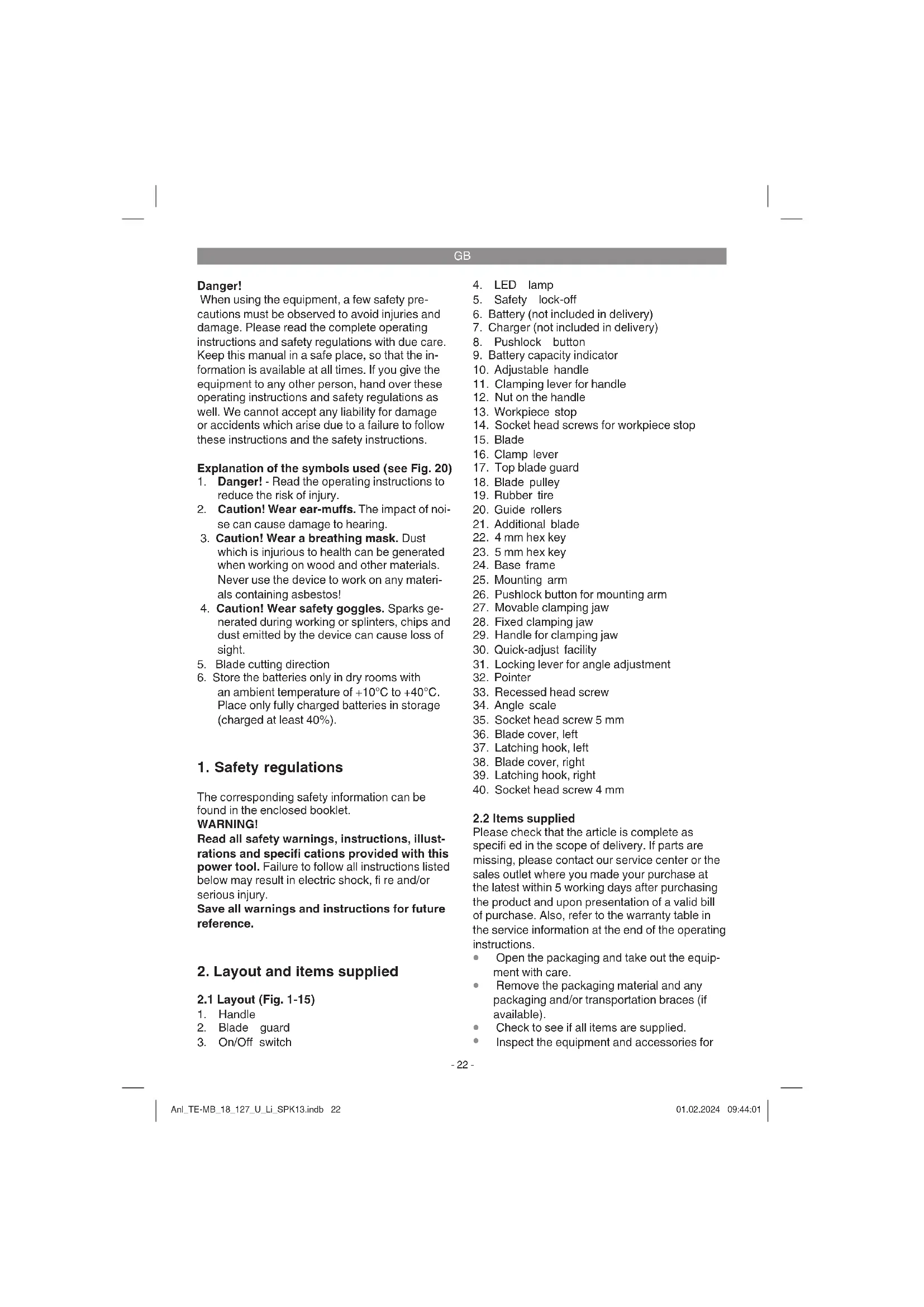
The cordless bandsaw is designed for cutting non-alloyed steel (e.g. structural steel), nonferrous metal (e.g. aluminium), sawn timber and wood-type materials. Alloyed steel, hardened steel and tempered metals are not allowed to be machined on this bandsaw. The cordless bandsaw is not designed for cutting firewood. No reactive or poisonous materials are allowed to be processed. Take care not to overload the machine.
The base frame is allowed to be used only with the cordless bandsaw with which it is delivered. Do not try to mount a different electric tool on it.
The equipment is to be used only for its prescribed purpose. Any other use is deemed to be a case of misuse. The user / operator and not the manufacturer will be liable for any damage or injuries of any kind caused as a result of this.
Please note that our equipment has not been designed for use in commercial, trade or industrial applications. Our warranty will be voided if the machine is used in commercial, trade or industrial businesses or for equivalent purposes.
General safety information
It is the user's responsibility to install and use the machine properly in accordance with the instructions issued by the manufacturer. If electromagnetic interference is noticed, it is the user's responsibility to eliminate said interference with
the technical devices mentioned in the section "Important information about the power connection".
Only blades suitable for the machine are allowed to be used. To use the machine properly you must also observe the safety information, the assembly instructions and the operating instructions to be found in these operating instructions.
All persons who operate and service the machine must be acquainted with these instructions and must be informed about potential hazards. It is also imperative to observe the accident prevention regulations in force in your area. The same applies for the general rules of health and safety at work.
The manufacturer will not be liable for any changes made to the machine nor for any damage resulting from such changes.
Even when the machine is used as prescribed it is still impossible to eliminate certain residual risk factors. The following hazards might arise in connection with the machine's construction and design:
- Damage to hearing if essential ear-muffs are not used.
- Harmful emissions of wood dust when used in closed rooms.
- Risk of accident through hand contact with the blade in the uncovered cutting zone.
- Risk of injury when changing the blade (risk of cuts).
Injuries from catapulted workpieces or parts of workpieces.
Crushed fingers.
Injuries from kickback. - Tilting of the workpiece due to inadequate support.
- Touching the blade.
- Dust and splinters can cause eye injuries. For this reason you must always wear safety goggles or spectacles with safety lenses.
- Dust presents a special danger. You should wear a suitable safety mask so that you are not forced to breathe in any dust.
Always wear tight-fitting protective clothing that is in perfect condition. - Long hair must be tied together, loose jewelry should not be worn.
The workpiece you want to cut must always be clamped securely. The workpiece must be shaped so that it can be clamped securely.
GB
4. Technical data
Cordless bandsaw
Motor power supply: 18 V DC
Idle speed: 240 min-1
Blade speed: 120 m/min
Blade: 1141 x 13 x 0.65 mm
Tooth pitch in teeth per 25.4 mm: 10/14 tpi (teeth per inch)
Max. cutting width: 127 mm
Maximum cutting height: 115 mm
Protection class: .
Weight: approx. 6 kg
Base frame for cordless bandsaw
Swiveling range: 0^ - 47^
Weight: 7 kg
Cutting capacity for rectangular tube:
90^a .. 100x80mm
Cutting capacity for circular tube:
90°: .100 mm
45°: 0 40 mm
Danger!
Sound and vibration
Sound and vibration values were measured in accordance with EN 60745.
Lsound pressure level 86 dB(A)
The impact of noise can cause damage to hearing.
Total vibration values (vector sum of three directions) determined in accordance with EN 60745.
Handle
Vibration emission value a_n < 2.5m / s^2 K uncertainty = 1.5m / s^2
The specified vibration value was established in accordance with a standardized testing method. It may change according to how the electric equipment is used and may exceed the specified value in exceptional circumstances.
The specified vibration value can be used to compare the equipment with other electric power tools.
The specified vibration value can be used for initial assessment of a harmful effect.
Keep the noise emissions and vibrations to a minimum.
Only use appliances which are in perfect working order.
Service and clean the appliance regularly.
Adapt your working style to suit the appliance.
Do not overload the appliance.
- Have the appliance serviced whenever necessary.
- Switch the appliance off when it is not in use.
Caution!
Residual risks
Even if you use this electric power tool in accordance with instructions, certain residual risks cannot be rules out. The following hazards may arise in connection with the equipment's construction and layout:
- Lung damage if no suitable protective dust mask is used.
- Damage to hearing if no suitable ear protection is used.
- Health damage caused by hand-arm vibrations if the equipment is used over a prolonged period or is not properly guided and maintained.
5. Before using the machine
Warning!
Always remove the battery before making adjustments to the machine.
5.1 General information
The machine must be set up where it can stand securely.
- All covers and safety devices must be properly fitted before the machine is switched on.
It must be possible for the blade to run freely.
- When working with wood that has been previously processed, watch out for foreign bodies such as nails or screws, etc.
Before you actuate the On/Off switch, make sure that the blade is correctly fitted and that the machine's moving parts run smoothly.
GB
- Important! The two hex keys (22/23) are stored in the adjustable handle (10) (see Fig. 2).
- Important! Please note that the tooth pitch of the blade you are using must match the material you want to cut. In the case of particularly hard materials or particularly large depths of blade penetration you should change the tooth pitch by changing the blade.
5.2 Adjusting the handle (Fig. 3)
The adjustable handle (10) can be fastened in various locking positions according to requirements.
- Release the clamping lever (11).
- Place the adjustable handle (10) in the required position.
- Lock the setting by refastening the clamping lever (11).
- Important! You can adjust the pretension of the clamping lever (11). To do so, hold the released clamping lever (11) firmly and adjust the nut (12) on the opposite side (clockwise: higher tension). Check the setting by closing the clamping lever (12) again. Keep repeating until you have the required tension.
5.3 Adjusting the workpiece stop (Fig. 4)
- Important! The workpiece stop (13) is set at the factory to bottom position.
- Caution! When you use the cordless bandsaw together with the base frame (24), the workpiece stop (13) must be set to bottom position.
- Caution! When you work without the base frame (24), the workpiece stop (13) should also be set to bottom position because this will increase the size of the guide face. Set the workpiece stop to a higher position only in exceptional cases.
- Slacken the two socket head screws (14) with the hex key (22) in order to be able to push the workpiece stop (13) to the required position. Then retighten the two socket head screws (14).
5.4 Information about the LED lamp (Fig. 1)
The machine has an LED lamp (4) for illuminating the cutting area.
- As soon as you press the On/Off switch (3), the LED lamp (4) will come on automatically.
A few seconds after you release the On/Off switch (3) again, the LED lamp (4) will switch off automatically.
5.5 Fitting/removing the blade (Fig. 5-7)
Warning!
Before you start to fit or remove the blade: Remove the battery!
To prevent injury: wear gloves when changing the blade!
Fitting:
To be able to remove the left-hand blade cover (36), slacken the socket head screw (40). With the latching hook (37) pushed and held in the up position, slide the blade cover (36) outwards.
To be able to remove the right-hand blade cover (38), slacken the socket head screw (40). With the latching hook (39) pushed and held in the up position, slide the blade cover (38) outwards.
Before you mount the new blade, clean the guide rollers (20) and the two blade pulleys (18). Make sure in particular that the rubber tire (19) is free of chips.
- Caution! A damaged rubber tire (19) must be replaced immediately.
To be able to fit the blade you must open the clamping mechanism for the blade. Open the clamping mechanism by turning the clamping lever (16) clockwise (see Fig. 6).
To fit the blade: start at the bottom part of the guide rollers (20), then continue around the blade pulleys (18), and finish at the top part of the blade guard (17).
- Caution! Pay attention to the running direction. The cutting angle of the teeth must point in running direction, i.e. towards the workpiece stop (13). (See the arrow on the two blade pulleys (18)).
Make sure that the new blade (15) runs freely in the guide rollers (20) and in the upper blade guard (17).
Tension the blade (15) by turning the clamping lever (16) counter-clockwise.
- Important! The blade must first be run in. Switch on the machine briefly and check how the blade is running. Check that the blade is running correctly before you start cutting.
- Refit the left-hand blade cover (36) and the right-hand blade cover (38). Make sure that both latching hooks (37, 39) latch home correctly. Fasten the two covers (36, 38) by tightening the socket head screws (40).
GB
Important! The width of the new blade must be at least as large as stipulated in section 4. Technical data. The teeth of the blade (15) must project beyond the guide rollers (20) (see Fig. 7d). If the new blade (15) is too narrow, the teeth will be damaged and the blade will become blunt.
Removing:
- Slacken the two socket head screws (40) and remove the two blade covers (36, 38).
- Slacken the blade (15) by turning the clamping lever (16) clockwise.
- Caution! When the blade is being removed, the tension might be released with a jerk causing the blade (15) to jump off the blade pulleys (18)!
To remove the blade: start at the top part of the blade guard (17), then continue around the blade pulleys (18), and finish at the guide rollers (20). - Refasten the two blade covers (36, 38) with the socket head screws (40).
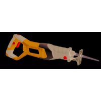
5.6 Bandsaw with base frame (Fig. 1a, 8)
5.6.1 Mounting / removing the bandsaw on / from the base frame (Fig. 9)
- Unlock the pushlock button (26) (see 5.6.2) and turn the mounting arm (25) downwards.
- Place the bandsaw on the base frame (24) so that the workpiece stop (13) rests on the base frame and the holes in the mounting arm (25) lie above the threaded holes in the bandsaw.
Use the 3 socket head screws (35) to fasten the bandsaw to the mounting arm (25). Do this with the hex key (23). - Important! The mounting arm (25) and the bandsaw must engage with each other in a positive fit.
5.6.2 Adjusting the pushlock button (Fig. 10)
The bandsaw is set at the factory in transport position and locked in bottom position.
To unlock the pushlock button (26) proceed as follows:
- Pull out the pushlock button (26) and hold it there.
- Turn the pushlock button counter-clockwise as far as the stop.
- Let go of the pushlock button.
The pushlock button (26) must be unlocked in order to be able to carry out any cuts.
- The bandsaw can also be locked in top position in addition to transport position. This setting is used, for example, when carrying out cleaning jobs or clamping the workpiece.
5.6.3 Setting angles on the base frame (Fig. 11)
Angle cuts from 0 to 45^ can be carried out using the base frame (24).
- Undo the locking lever (31) by moving it counter-clockwise.
- Important! By changing the position you can readjust the pretension of the clamping lever (31). Proceed as follows:
-
Pull up the clamping lever (31) and hold it there.
-
You can now rotate the clamping lever without changing the tension.
-
Let go of the locking lever (31) again.
-
Turn the mounting arm (25) to the required angle.
- Then re-tighten the clamping lever (31).
5.6.4 Precision adjustment of the angle scale (Fig. 8/11)
- You can readjust the angle indicator if required. To do so you will need a 90^ stop angle (not included with this product).
Slacken the clamping lever (31). - Place a 90^ stop angle between the fixed clamping jaw (28) and the blade (15).
- Turn the mounting arm (25) to the point where the angle between the fixed clamping jaw (28) and the blade (15) equals exactly 90^ .
- Tighten the clamping lever (31) in order to secure this setting.
- Then undo the recessed head screw (33) using a screwdriver (not included with this product).
- Adjust the pointer (32) to position 0^ on the angle scale (34).
Finally, secure this setting by tightening the recessed head screw (33).
5.6.5 Clamping the workpieces (Fig. 12)
- To clamp a workpiece in the base frame (24) you must first release the movable clamping jaw (27) by turning the handle (29) counterclockwise.
For small adjust widths: Turn out the handle (29) to the point where the workpiece can be inserted between the fixed clamping jaw (28) and the movable clamping jaw (27).
For large adjust widths: Swing up the quick-adjust facility (30). You can then use the
GB
handle (29) to pull out or push in the movable clamping jaw (27).
- Then swing the quick-adjust facility (30) back down again in order to be able to clamp the workpiece.
- Clamp the workpiece by turning the handle (29) clockwise.
- Caution! Long workpieces must be secured against falling off at the end of the cutting operation. You can use, for example, a roller stand or similar.
6. Operation
6.1 Charging the Li battery pack (Fig. 13/14)
- Remove the battery pack (6) from the handle, pressing the pushlock button (8) downwards to do so.
- Check that your mains voltage is the same as that marked on the rating plate of the battery charger. Insert the power plug of the charger (7) into the mains socket outlet. The green LED will then begin to flash.
- Push the battery pack onto the battery charger.
In section 10 (Charger indicator) you will find a table with an explanation of the LED indicator on the charger.
If the battery pack fails to charge, check for the following:
- voltage at the power socket
whether there is good contact at the charging contacts of the charging unit
If the battery pack still fails to charge, send
the charger and charging adapter
and the battery pack
to our customer service center.
To ensure that items are properly packaged and delivered when you send them to us, please contact our customer service or the point of sale at which the equipment was purchased.
When shipping or disposing of batteries and cordless tools, always ensure that they are packed individually in plastic bags to prevent short circuits and fi res.
To ensure that the battery pack provides long service, you should take care to recharge it promptly. You must recharge the battery pack when you notice that the performance of the device drops. Never allow the battery pack to become fully discharged. This will cause it to develop a defect.
6.2 Battery capacity indicator (Fig. 15/Item 9) Press the battery capacity indicator switch (a).
The battery capacity indicator (9) shows the charge status of the battery using 3 LEDs.
All 3 LEDs are lit:
The battery is fully charged.
2 or 1 LED(s) are lit:
The battery has an adequate remaining charge.
1 LED fl ashes:
The battery is empty, recharge the battery.
All LEDs blink:
The battery temperature is too low. Remove the battery from the equipment, keep it at room temperature for one day. If the fault reoccurs, this means that the rechargeable battery has undergone exhaustive discharge and is defective. Remove the battery from the equipment. Never use or charge a defective battery.
6.3 On/Off switch (Fig. 16)
- Press the safety lock-off (5) in order to release the On/Off switch (3).
- Actuate the On/Off switch (3).
- Important! You can let go of the safety lockoff (5) as soon as the On/Off switch (3) was actuated.
To switch off the saw, let go of the On/Off switch (3) again.
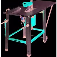
6.4 Making cuts with the bandsaw in hand-guided mode (Fig. 17)
The bandsaw is used without the base frame (24). Remove the base frame (24) if necessary (see 5.6.1).
- Set the adjustable handle (10) as described in section 5.2.
- Set the workpiece stop (13) as described in section 5.3.
- The material you want to cut must be clamped securely.
- Hold the machine firmly with both hands; use the one hand on the handle (1) and the other hand on the adjustable handle (10).
Take care to maintain a steady foothold.
GB
- Switch on the bandsaw as described in section 6.3.
- Move the bandsaw with its blade (15) in front of the workpiece.
- First place the workpiece stop (13) against the workpiece and align the blade with the cutting plane.
Now guide the bandsaw with a firm grip to the workpiece and cut into it carefully. - Important! Do not exert excessive pressure on the blade! This way you will obtain the straightest possible cut while also prolonging the life of the blade.
- Do not cut any cross-sections larger than those described in section 4. Technical data.
- Warning! If you are unable to cut through the workpiece in a single pass, there will be a greater risk of the blade getting jammed and causing kickback!
6.5 Making cuts with the bandsaw in stationary mode (Fig. 18/19)
The bandsaw is used with the base frame (24). Mount the base frame (24) if necessary (see 5.6.1).
- Place the base frame on a level surface where it can stand firmly.
- Set the desired angle as described in section 5.6.3.
- Caution! Depending on the set angle, the cutting width or the cutting height might become smaller. (See 4. Technical data)
Use the pushlock button (26) to lock the bandsaw in the top position (see 5.6.2).
- Clamp the workpiece securely as described in 5.6.5.
- Important! After every new adjustment we recommend you to make a trial cut in order to check the new settings.
- Hold the bandsaw firmly by the handle (1) and release the pushlock button (26) as described in 5.6.2.
- Switch on the bandsaw as described in section 6.3.
Now guide the bandsaw with a firm grip to the workpiece and cut into it carefully.
- Do not exert excessive pressure on the blade! This way you will obtain the straightest possible cut while also prolonging the life of the blade.
- Warning! The blade must have stopped moving before the workpiece is removed.
6.6 Transport
- Set the angle on the base frame (24) to 0^ and lock it in place with the clamping lever (31) (see 5.6.3).
Use the pushlock button (26) to lock the bandsaw in the bottom position (see 5.6.2). - Clamp the movable clamping jaw (27) against the fixed clamping jaw (28) (see 5.6.5).
- Transport the machine by lifting it only by the handle (1), the adjustable handle (10) or the base plate (24).
- Never use the guards for handling or transporting purposes.
7. Cleaning, maintenance and ordering of spare parts
Danger!
Always pull out the mains power plug before starting any cleaning work.
7.1 Cleaning
- Keep all safety devices, air vents and the motor housing free of dirt and dust as far as possible. Wipe the equipment with a clean cloth or blow it with compressed air at low pressure.
We recommend that you clean the device immediately each time you have finished using it.
Clean the equipment regularly with a moist cloth and some soft soap. Do not use cleaning agents or solvents; these could attack the plastic parts of the equipment. Ensure that no water can seep into the device. The ingress of water into an electric tool increases the risk of an electric shock.
7.2 Carbon brushes
In case of excessive sparking, have the carbon brushes checked only by a qualifi ed electrician. Danger! The carbon brushes should not be replaced by anyone but a qualifi ed electrician.
7.3 Maintenance
There are no parts inside the equipment which require additional maintenance.
GB
7.4 Ordering replacement parts:
Please quote the following data when ordering replacement parts:
Type of machine
Article number of the machine
- Identification number of the machine
- Replacement part number of the part required For our latest prices and information please go to www.Einhell-Service.com
8. Disposal and recycling
The equipment is supplied in packaging to prevent it from being damaged in transit. The raw materials in this packaging can be reused or recycled. The equipment and its accessories are made of various types of material, such as metal and plastic. Never place defective equipment in your household refuse. The equipment should be taken to a suitable collection center for proper disposal. If you do not know the whereabouts of such a collection point, you should ask in your local council offices.
9. Storage
Store the equipment and accessories in a dark and dry place at above freezing temperature. The ideal storage temperature is between 5 and 30^ . Store the electric tool in its original packaging.
Important! We recommend you to slacken the blade (see 5.5) if you are not going to use the machine for a long time. We also recommend you to protect the guide rollers (20) with mineral oil during long periods of storage.
10. Charger indicator
| Indicator status Explanations and actions | ||
| Red LED Green LED | ||
| Off | Flashing | Ready for use The charger is connected to the mains and is ready for use; there is no battery pack in the charger |
| On Off Charging | The charger is charging the battery pack in quick charge mode. The charging times are shown directly on the charger. Important! The actual charging times may vary slightly from the stated charging times depending on the existing battery charge. | |
| Off | On | The battery is charged and ready for use. The unit then changes over to gentle charging mode until the battery is fully charged. To do this, leave the rechargeable battery on the charger for approx. 15 minutes longer. Action: Take the battery pack out of the charger. Disconnect the charger from the mains supply. |
| Flashing Off | Adapted charging | |
| The charger is in gentle charging mode. For safety reasons the charging is performed less quickly and takes more time. The reasons can be: - The rechargeable battery has not been used for a very long time. - The battery temperature is outside the ideal range. Action: Wait for the charging to be completed; you can still continue to charge the battery pack. | ||
| Flashing Flashing Fault | Charging is no longer possible. The battery pack is defective. Action: Never charge a defective battery pack. Take the battery pack out of the charger. | |
| On On Temperature fault | The battery pack is too hot (e.g. due to direct sunshine) or too cold (below 0°C). Action: Remove the battery pack and keep it at room temperature (approx. 20°C) for one day. | |
GB

For EU countries only
Never place any electric power tools in your household refuse.
To comply with European Directive 2012/19/EC concerning old electric and electronic equipment and its implementation in national laws, old electric power tools have to be separated from other waste and disposed of in an environment-friendly fashion, e.g. by taking to a recycling depot.
Recycling alternative to the return request:
As an alternative to returning the equipment to the manufacturer, the owner of the electrical equipment must make sure that the equipment is properly disposed of if he no longer wants to keep the equipment. The old equipment can be returned to a suitable collection point that will dispose of the equipment in accordance with the national recycling and waste disposal regulations. This does not apply to any accessories or aids without electrical components supplied with the old equipment.
Please note that batteries and lamps (e.g. light bulbs) must be removed from the tool before it is disposed of.
The reprinting or reproduction by any other means, in whole or in part, of documentation and papers accompanying products is permitted only with the express consent of the Einhell Germany AG.
Subject to technical changes.
GB
Service information
We have competent service partners in all countries named on the guarantee certificate whose contact details can also be found on the guarantee certificate. These partners will help you with all service requests such as repairs, spare and wearing part orders or the purchase of consumables.
Please note that the following parts of this product are subject to normal or natural wear and that the following parts are therefore also required for use as consumables.
| Category Example | |
| Wear parts* Carbon brushes, Battery | |
| Consumables* Blade | |
| Missing parts |
- Not necessarily included in the scope of delivery!
In the effect of defects or faults, please register the problem on the internet at www.Einhell-Service.com. Please ensure that you provide a precise description of the problem and answer the following questions in all cases:
Did the equipment work at all or was it defective from the beginning?
Did you notice anything (symptom or defect) prior to the failure?
What malfunction does the equipment have in your opinion (main symptom)?
Describe this malfunction.
GB
Warranty certificate
Dear Customer,
All of our products undergo strict quality checks to ensure that they reach you in perfect condition. In the unlikely event that this equipment develops a fault, please contact our service department at the address shown on this guarantee card. You can also contact us by telephone using the service number shown. Please note the following terms under which guarantee claims can be made:
-
These guarantee terms apply solely to consumers, i.e. natural persons, who do not want to use this product in connection with either their commercial or other self-employed activities. These guarantee terms regulate additional guarantee services which the undermentioned manufacturer promises to buyers of its new products in addition to their statutory rights of guarantee. Your statutory rights of guarantee are not affected by this guarantee. Our guarantee is free of charge to you.
-
The guarantee services cover only defects due to material or manufacturing faults on the new product which you have bought in the European Union from the undermentioned manufacturer and are limited to either the rectification of said defects or the replacement of the product, whichever we prefer. Please note that only equipment under the brand name "Professional" has been designed for use in commercial, trade or professional applications. For all other products the guarantee is invalidated if the equipment is used within the guarantee period in commercial, trade or industrial applications or for other equivalent activities.
-
Our guarantee does not cover:
-
Damage to the equipment caused by failure to comply with the installation/assembly instructions or by unprofessional installation; damage caused by failure to comply with the operating instructions (e.g. connection to the wrong mains voltage or current type); damage caused by failure to comply with the maintenance and safety regulations; damage caused by exposing the equipment to abnormal environmental conditions; damage resulting from poor care and maintenance.
- Damage to the equipment caused by misuse or incorrect applications (e.g. overloading the equipment or using non-approved attachments or accessories); damage caused by foreign bodies (e.g. sand, stones, dust, ...) getting inside the equipment. Damage in transit; damage caused by force or external influences (e.g. by dropping the equipment).
-
Damage to the equipment or parts of the equipment which is owed to use-related, normal or otherwise natural wear. For example, batteries and battery packs are manufactured with a cycle limit for design-related reasons. Wear is negatively influenced in particular by load demands and charging speeds as well as exposure to heat, cold, vibration and impact.
-
The guarantee is valid for a period of 2 years starting from the purchase date of the equipment. Guarantee claims must be submitted before the end of the guarantee period and within two weeks of the defect being noticed. No guarantee claims will be accepted after the end of the guarantee period. The original guarantee period remains applicable to the equipment even if repairs are carried out or parts are replaced. In such cases, the work performed or parts fitted will not result in an extension of the guarantee period, and no new guarantee will become active for the work performed or for any replacement parts fitted. This also applies if on-site service is used.
- To assert your guarantee claim, register the defective equipment at: www.Einhell-Service.com. You will need to provide proof of purchase of the new item of equipment. Equipment returned without such proof or without a rating plate are excluded from the guarantee services because of the lack of traceability. If the defect is covered by our guarantee, then either the item in question will be repaired immediately and returned to you or we will send you a new replacement.
- If you have taken the equipment with you to a different EU country than where you bought it, we will arrange for a local service partner to provide the guarantee services. If you take the equipment outside the EU, the guarantee will not apply.
Of course, we are also happy to offer a chargeable repair service for any defects which are not covered or no longer covered by the scope of this guarantee. To take advantage of this service, please send the equipment to our service address. We draw attention to the restrictions of this guarantee concerning wear parts, consumables and missing parts as presented in the service information included in this operating manual.
Warrantor/Service:
Einhell UK Ltd, Unit 10, 1st Floor, Champion's Business Park, Arrowe Brook Road, Upton, Wirral, CH49 0UQ
F
Danger!
Chere clientele, cher client.
5.4 Pokyny k LED lampé (obr. 1)
5.4 Pokyny k LED lampe (obr.1)
- Pristoj má jegnu LED lampu (4) na osvetlenie oblasti rezu.
LED lampa (4) sa okamzite automaticky rozs-vieti, ked stlacite spinac zap/vyp (3).
LED lampa (4) sa po niekol'kych sekundach automaticicky vypne, ked spina' Zap/vyp (3) znovu uvol'nite.
Akumulator je uplne nability.
Spanning motor: 18 V DC
Nullasttoerental: 240 min
Negotovost KwA 3 dB(A)
Uporabljaje zašcito za ušesa.
Svetita 2 ali 1 lucka LED:
90^ .. 100x80mm
45^ .. 40× 40mm
Capacitate de taiere teava rotunda:
Stimata clienta, stimate client.
△iaipean dovtuw ava 25,4mm:
10/14 AI (sovia ava ivra)
Evnpwon yia to epbic
5. Pre puštanja u pigeon
Upozorenje!
Pre nga sto vrsite podesavanja uredaju uvek izvadite akumulator.
5.1 Opste
Mašinu treba da postavite stabilno.
Pre puštanja u rad moraju biti montirani svipoklopci i sigurnosni uredaji.
Traka testere mora se slobodno kretati.
Kod drveta koje je vec obradivano voditi računa o stranim telima, kao što su npr. ekseri ili zavrtnji itd.
RS
- Pre Ngo što ukljucite prekidač za ukljucivanje/iskljucivanje, proverite da li je traka testere pravilno montirana i da li se po-kretni delovi nesmetano kreću.
- Napomena! Oba ključa za zavrtnje sa šestostranim upustom (22/23) su smestena u podesivoj drsci (10) (vidi sliku 2).
Napomena! Obratite paznju da korak zubaca. trake testere mora biti prislagoden materijalu koji se reze. Kod veoma tvrdih materijala ili posebno velikog zahvatanja trake testere korak zubaca, a time i traka testere se mora promeniti.
5.2 Podesavanje drske (sika 3)
- Podesiva drska (10) se po potrebi moze fiksi-rati u razlicitim položajima zabravljivanja.
- Otpustite polugu za stezanje (11).
Postavite podesivu drsku (10) u zeJenji položaj. - Fiksirajte podesavanje tako sto cete poluguza stezanje (11) ponovo zatvoriti.
Napomena! Sila prednaprezanja poluge za stezanje (11) se moze podesavati. U tu svruh cvrsto drzite optušenu polugu za stezanje (11) i podesite navrku (12) na suprotnoj strani (u smeru kretanja kazaljke na satu: veça silica zatezanja). Proverite podesavanje takto sto cete polugu za stezanje (12) ponovo zatvoriti. Ponavlajte ovaj postupak sve dok ne bude postignuta zeljena sila zatezanja.
5.3 Podesavanje graničnika obratka (slika 4)
- Napomena! Graničnik obratka (13) je u stanju prilikom isporeuke podesen na rajniži položaj.
- Oprez! Ukoliko akumulatorsku tračnu testeru koristite zajedno sa postoljem (24), grančnik obratka (13) mora biti poděšen na rajnizi položaj.
- Oprez! U slučaju korišćenja bez postolja (24) graničnik obratka (13) takode treba biti poděšen na majnizi položaj, jer Čeze time povećati površinu vodena. Podešavanje graničína obratka u visi položaj vršite samo u izuzetnim slučajevima.
- Otpustite oba zavrtnja sa šestostranim upustom (14) pomocu kljuca za zavrtnej sa šestostranim upustom (22), kako biste granicnik obatrka (13) mogla da pomerite u Željeni položaj. Nakon toga ponovo zategnite oba zavrtnja sa šestostranim upustom (14).
5.4 Napomene za LED lampicu (slika 1)
- Urejaj raspolaje LED lampom (4) za osvetl-javanje područja rezanja.
LED lampa (4) se uključuje automatski, Čim pritisnete prekidać za uključivanje / isključivanje (3).
LED lampa (4) se nakon nekoliko sekundi automatski isključuje, Čim ponovo opustite prekidać za ukljucivanje / isključivanje (3).
5.5 Montaza / demontaza trake testere (slika 5-7)
Upozorenje!
Pre montaze i demontaze trake testere: Skinuti akumulator!
Prilikom zamene trake testere nosite rukavice, kakibiste izbegli povrede!
Montaza:
Da bi mogli da demontirate leviPoklopac trake testere (36),otpustite zavrtanj sa sestostranim upustom (40).PomeritePoklopac trake testere (36) prema van dok drzite kuku za nasedanje (37) stisutu prema gore.
Da bi mogli da demontirate desniPoklopac trake testere (38),otpustite zavrtanj sa steastrostrinum upustom (40).PomeritePokpaco trake testere (38) prema van dok drzite kuku za nasedanje (39) stisutu prema gore.
Pre montaze nove trake testere oistite tockicze za vodenje (20), kao i koturove trake testere (18).Posebno vodite raçauna o tome da nalegajuca gumena povrsina (19) bude bez opiljaka.
- Oprez! Ostecena nalegajuca gumena povrsina (19) se mora odmah zameniti.
- Da bi mogli da montirate traku testere, mehanizam za stezanje mora biti otvoren za traku testere. Otvorite mehanizam za stezanje taksto okrenete ručku za stezanje (16) u smeru kazaljke na satu (vidi sliku 6).
Za montazu trake testere pocnite sa donjim delom tockica za vodenje (20) i mastavite oko koturova trake testere (18) do gomjeg dela stitnika trake testere (17).
- Oprez! Voditi računa o smeru kretanja, tj. kosina rezanja zubaca moraPokazivati u smeru kretanja, odn.prema graničiku obratka (13). (vidi strelicu na oba kotura lista testere (18)).
- Uverite se da se nova traka testere (15) slobodno krece u tockicima za vodenje (20) i u gornjem stitniku trake testere (17).
RS
- Zategnite list traku testere (15) okretanjem poluge za stezanje (16) u suprotnom smeru od kretanja kazaljke na satu.
- Napomena! Traka testere najpre mora da se uhoda. Uklučite masinu samo na kratkovi pri tome proverite kretanje trake testere. Pre početka rezanja proverite da li se traka korěktno krece.
Opet postavite levi (36) i desniPoklopac trake testere (38). Uverite se da obe kuke za nase danje (37, 39) ispravo nasednu. FiksirajeobaPoklopa (36, 38) da pritezanjem zavrtnja sa sestostranim upustom (40).
Napomena! Sirina nove trake testere mora biti najmanje onolika, koliko je navedeno u tacki 4. Tehnički podaci. Zupci trake testere (15) moraju da vire ispred tockica za vodenje (20) (vidi sliku 7d). U slucaju da je nova traka testere (15) suviše uska, zupci ce se ošteiti i traka testere ce biti tupa.
Demontaža:
- Otpustite zavrtnja sa šestostranim upustom (40) i skinite obaPoklopca trake testere (36, 38).
- Otpustite traku testere (15) taksto cete polugu za stezanje (16) okrenuti u smeru kretanja kazaljke na satu.
- Oprez! Prilikom demontaze se napregnutost se moze naglo opustiti i traka testere (15) moze iskočiti sa koturova trake testere (18)!
Da bi izvadili traku testere pocnite sa gornjim delom stitnika trake testere (17) i nastavite oko koturova lista testere (18), do tockica za vodenje (20). - Ponovno fiksirajte obaPoklopca (36, 38) pomocu zavrtnja sa sestostranim upustom (40).
90^ .. 100x80mm
Jeff Dong/Product-Management
First CE:22
Art-No.:45.042.15
I-No.:21023
Subject to change without notice
Archive-File/Record: NAPR030599
Documents registrar: Korbinian Wasmeier
Wiesenweg 22, D-94405 Landau/Isar
Gh Clll t 1. 1 1 1 1 1 1 1 1 1 1 1 1 1 1 1 1 1 1 1 1 1 1 1 1 1 1 1 1 1 1 1 1 1 1 1 1 1 1 1 1 1 1 1 1 1 1 1 1 1 1 0

Declaration of conformity
We, Einhell UK Ltd
Champions Business Park, First Floor Unit 10, Arrowe Brook Rd, Upton, Wirral CH49 0AB, United Kingdom
declare the conformity to UK standards and legislation was assessed for:
Cordless Bandsaw TE-MB 18/127 U Li (Einhell)
UK legislation
Simple Pressure Vessels (Safety) Regulation
Electrical Equipment (Safety) Regulation
Radio Equipment Regulation
Personal Protective Equipment Regulation
The Ecodesign for Energy-Related Products and Energy Information Regulation
The Restriction of the Use of Certain Hazardous Substances in Electrical and Electronic Equipment Regulation
Nolse Emisslon in the Environment by Equipment for use Outdoors Regulation
Annex V
Annex VI
Noise:measuredL = dB A):guaranteed L_w = dB A
P = kW; L/0 = cm
Approved Body:
Supply of Machinery (Safety) Regulation
Annex IV
Approved Body:
Certificate No.:
Standards: BS EN 60745-1; BS EN 60745-2-20; BS EN IEC 55014-1; BS EN IEC 55014-2

Tom Chambers, Managing Director Einhall UK Ltd
Wirral, 2023.12.04
Archive-File/Record: NAPR030599
Article Number: 45.042.15 I-No.: 21023
Subject to change without notice Wiesenweg 22, 94405 Landau/Isar, Germany
Documents registrar: Korbinian Wasmeier
EH 02/2024 (01)


- Explanation of the symbols used (see Fig. 20)
- Safety regulations
- WARNING!
- Layout and items supplied
- Layout (Fig. 1-15)
- Items supplied
- GB
- Danger!
- Proper use
- General safety information
- Technical data
- Cordless bandsaw
- Base frame for cordless bandsaw
- Sound and vibration
- Handle
- Keep the noise emissions and vibrations to a minimum.
- Caution!
- Residual risks
- Before using the machine
- General information
- Adjusting the handle (Fig. 3)
- Adjusting the workpiece stop (Fig. 4)
- Information about the LED lamp (Fig. 1)
- Fitting/removing the blade (Fig. 5-7)
- Before you start to fit or remove the blade: Remove the battery!
- To prevent injury: wear gloves when changing the blade!
- Fitting:
- Removing:
- Bandsaw with base frame (Fig. 1a, 8)
- Mounting / removing the bandsaw on / from the base frame (Fig. 9)
- Adjusting the pushlock button (Fig. 10)
- Setting angles on the base frame (Fig. 11)
- Precision adjustment of the angle scale (Fig. 8/11)
- Clamping the workpieces (Fig. 12)
- Operation
- Charging the Li battery pack (Fig. 13/14)
- Battery capacity indicator (Fig. 15/Item 9) Press the battery capacity indicator switch (a).
- All 3 LEDs are lit:
- or 1 LED(s) are lit:
- LED fl ashes:
- All LEDs blink:
- On/Off switch (Fig. 16)
- Making cuts with the bandsaw in hand-guided mode (Fig. 17)
- Making cuts with the bandsaw in stationary mode (Fig. 18/19)
- Transport
- Cleaning, maintenance and ordering of spare parts
- Cleaning
- Carbon brushes
- Maintenance
- Ordering replacement parts:
- Disposal and recycling
- Storage
- Charger indicator
- Recycling alternative to the return request:
- Service information
- Warranty certificate
- Dear Customer,
- F
- Pokyny k LED lampé (obr. 1)
- Pokyny k LED lampe (obr.1)
- Uporabljaje zašcito za ušesa.
- Svetita 2 ali 1 lucka LED:
- Evnpwon yia to epbic
- Pre puštanja u pigeon
- Upozorenje!
- Opste
- RS
- Podesavanje drske (sika 3)
- Podesavanje graničnika obratka (slika 4)
- Napomene za LED lampicu (slika 1)
- Montaza / demontaza trake testere (slika 5-7)
- Pre montaze i demontaze trake testere: Skinuti akumulator!
- Prilikom zamene trake testere nosite rukavice, kakibiste izbegli povrede!
- Montaza:
- Demontaža:
- Declaration of conformity
- Cordless Bandsaw TE-MB 18/127 U Li (Einhell)
- UK legislation
Brand : EINHELL
Model : TE-MB 18/127 U Li
Category : Electric saw