ProMax Garden Automatic 60005 - Water pump OASE - Free user manual and instructions
Find the device manual for free ProMax Garden Automatic 60005 OASE in PDF.
| Technical Specifications | Maximum flow rate: 6000 L/h, Maximum head height: 5 m, Power: 600 W, Motor type: electric, Power supply: 230 V |
|---|---|
| Usage | Ideal for garden watering, clear water pumping, and filling ponds. |
| Maintenance and Repair | Regularly check the inlet filter, clean impurities, and store protected from frost. |
| Safety | Use only in dry conditions, avoid contact with water during handling, unplug before any intervention. |
| General Information | Warranty: 2 years, Weight: 6 kg, Dimensions: 40 x 30 x 25 cm. |
Frequently Asked Questions - ProMax Garden Automatic 60005 OASE
Download the instructions for your Water pump in PDF format for free! Find your manual ProMax Garden Automatic 60005 - OASE and take your electronic device back in hand. On this page are published all the documents necessary for the use of your device. ProMax Garden Automatic 60005 by OASE.
USER MANUAL ProMax Garden Automatic 60005 OASE
Translation of the original Operating Instructions
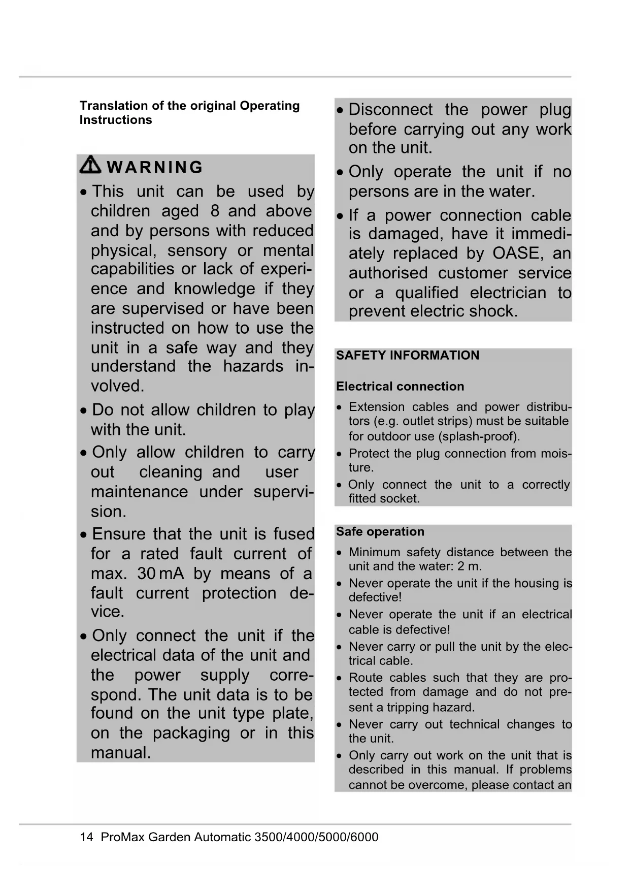
- This unit can be used by children aged 8 and above and by persons with reduced physical, sensory or mental capabilities or lack of experi- ence and knowledge if they are supervised or have been instructed on how to use the unit in a safe way and they understand the hazards in- volved.
- Do not allow children to play with the unit.
- Only allow children to carry out cleaning and user maintenance under supervi- sion.
- Ensure that the unit is fused for a rated fault current of max. 30 mA by means of a fault current protection de- vice.
- Only connect the unit if the electrical data of the unit and the power supply corre- spond. The unit data is to be found on the unit type plate, on the packaging or in this manual.
- Disconnect the power plug before carrying out any work on the unit.
- Only operate the unit if no persons are in the water.
- If a power connection cable is damaged, have it immedi- ately replaced by OASE, an authorised customer service or a qualified electrician to prevent electric shock. SAFETY INFORMATION Electrical connection
- Extension cables and power distribu- tors (e.g. outlet strips) must be suitable for outdoor use (splash-proof).
- Protect the plug connection from mois- ture.
- Only connect the unit to a correctly fitted socket. Safe operation
- Minimum safety distance between the unit and the water: 2 m.
- Never operate the unit if the housing is defective!
- Never operate the unit if an electrical cable is defective!
- Never carry or pull the unit by the elec- trical cable.
- Route cables such that they are pro- tected from damage and do not pre- sent a tripping hazard.
- Never carry out technical changes to the unit.
- Only carry out work on the unit that is described in this manual. If problems cannot be overcome, please contact anDE
authorised customer service point or, if in doubt, the manufacturer.
- Only use original spare parts and ac- cessories for the unit.
INFORMATION ABOUT THIS
OPERATING MANUAL You made a good choice with the pur- chase of this product ProMax Garden Automatic 3500/4000/5000/6000. Prior to commissioning the unit, please read the instructions of use carefully and fully familiarise yourself with the unit. Ensure that all work on and with this unit is only carried out in accordance with these instructions. Adhere to the safety information for the correct and safe use of the unit. Keep these instructions in a safe place! Please also hand over the instructions when passing the unit on to a new owner. Warnings used in these instructions Warnings The warning information is categorised by signal words, which indicate the extent of the hazard. WARNING
- Indicates a possibly hazardous situati- on.
- Non-observance may lead to death or serious injuries. NOTE Information for the purpose of clarification or for preventing possible damage to assets or to the environment. Cross-references used in these in- structions A reference to a figure, e.g. figure A.
- Reference to another section. PRODUCT DESCRIPTION Overview
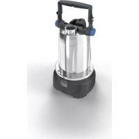
Transport handle with ON/OFF button (13)
Connection, pressure side
Connection, suction side
Non-return valve opener
Power connection cable
Intended use Only use the product described in this manual as follows:
- For transferring water from and drain- ing basins or ponds/pools.
- For irrigating and watering.
- For pumping clear water or rain water.
- Extraction of water from a well. – Only for irrigation and watering pur- poses!
- For pumping the water out of water butts/rain barrels or cisterns. – Size of the particles in the water: max. 2 mm.
- Operate in accordance with instruc- tions. (→ Technical data)
Possible incorrect use The following restrictions apply to the unit:
- Do not use for long-term operation (e.g. continuous recirculation of the wa- ter in a pond).
- Not suitable for salt water.
- Never use for pumping dirty wa- ter/waste water.
- Do not connect to the domestic water supply.
- Not suitable for drinking water.
- Do not use in conjunction with chemi- cals, foodstuff, easily flammable or ex- plosive substances.
NOTE For permanent installation of the pump, use flexible compression-proof hoses to connect it to the pipe network to reduce the noise of the pump. NOTE If the pump is used as a booster pump, ensure that the max. internal pressure of 6 bar on the pressure side is not exceed- ed.
- The pump pressure is added to the pre-pressure.
- Example: Pre-pressure = 1 bar, max. pressure of the pump = 4.5 bar, total pressure = 5.5 bar.
- Install the pump in a horizontal and stable position in a dry place. – For permanent installation of the pump, ensure that a sufficiently large collecting basin can be positioned underneath the discharge screw for emptying the pump.
- If possible, install the pump in a higher position than the container/reservoir from which the water is to be pumped. If this is not possible, a pressure-proof valve must be fitted between the pump and the suction hose.
- Only use vacuum-proof pressure hoses on the pressure and suction side. NOTE OASE recommends: Additionally fasten the suction hose (e.g. by tying it to a wooden stake) to relieve the weight of the hose on the pump.
- Screw a suction and pressure hose with 25.0 mm internal diameter (1") on- to the connections.DE
OPERATION Start-up of the device It is necessary to fill the pump and expel the air from the suction line before using. It can take several minutes to expel air from the suction line. How to proceed:
1. Unscrew the filter cover. A screwdriver
can be inserted from the side into the recesses of the cover to aid unscrew- ing.
2. Open the shut-off device in the pres-
3. Pour water into the infill opening of the
pre-filter until it overflows. At the same time, keep the non-return valve opener open until the water has expelled any remaining air from the filter.
4. Screw the filter cover back on.
5. Insert the power plug into the socket.
– The pump is ready for operation.
6. Switch on the pump. (→ Operation)
– The pump starts pumping immedi- ately. The emerging water still con- tains some air. NOTE If no water is taken in after 5 minutes, the dry run protection of the pump is activat- ed.
7. Close the shut-off device of the pres-
sure line as soon as there is no more air in the emerging water. Air has now been expelled from the suction line.
Shutting down the pump NOTE Rinse out the pump with clean water after use. How to proceed:
1. Switch off the pump
2. Disconnect the power plug.
3. Depressurise the pressure line by
opening the water withdrawal points.
4. Also open any non-return valves fitted
in the suction line. – When the pump is switched off, re- sidual water in the hose may flow back and out of the pump intake. If the pump is to be completely removed:
5. Remove the connected hoses on the
pressure and suction side.
6. Undo the water drain screw and tip the
pump to allow the residual water to drain out.
7. Screw in the water drain screw again.
- During operation, sensors monitor the water flow and water pressure to pre- vent the pump, for example, from run- ning dry. Depending on the event (in- sufficient flow rate or water pressure below 1.5 bar) the pump changes to the operating state stand-by or switch- es off.
- The lit or flashing LEDs in the ON/OFF button indicate the respective operating status. (→ Operating status and atten- dant LED displays) Operating modes Mode A (delivery state):
- Connect the pump to the power supply. – When all LEDs are lit, the pump is ready for operation (stand-by). (→ Operating status and attendant LED displays)
- Switching on: Press the ON/OFF but- ton for less than 3 s.
- Switching off: Press the ON/OFF but- ton again.
Mode B: In this mode the pump can, for example, be switched on and off by a timer.
- The pump switches on as soon as it is connected to the power supply. Changing the mode
- Press the ON/OFF button for at least 10 s. – Mode A active: The LEDs blue, yel- low and red light up once. – Mode B active: The LEDs blue, yel- low and red flash 3 times. Switching on the pump following a malfunction The LEDS yellow and red are lit when the pump switches off due to a malfunction.
- Press the ON/OFF button for at least 3 s, but not longer than 6 s to switch the pump on again.
Operating status and attendant LED displays LED Operating status User Blue Yel- low Red Flashing fre- quency
Pump is operational. Switch on the pump.
No malfunctions, pump is running.
4× per second No malfunctions, the pump will soon switch to standby.
No malfunctions, the pump is in standby.
Pump is not taking in water. 1st stage - dry run protection Wait
1× per second Pump is not taking in water.
2× per second Pump is not taking in water.
LED Operating status User Blue Yel- low Red Flashing fre- quency
- In the 4th stage the pump switches into waiting mode.
4th stage - dry run protec- tion. The pump is in waiting mode for 120 s, then the cycle starts again, max. 2× Wait or find the cause.
Malfunction, pump has run through cycle 3× Disconnect the power plug, check the suction side, reconnect the power plug.
Malfunction, 18 unsuccessful start attempts Disconnect the power plug, check the pressure side, reconnect the power plug.
Switching on the pump following a malfunction The LEDS yellow and red are lit when the pump switches off due to a malfunction.
- Press the ON/OFF button for at least 3 s, but not longer than 6 s to switch the pump on again.
Malfunction Cause Remedy Pump does not start. The pump is switched off. Switch on the pump. Power supply interrupted Check the electrical plug connections. The fault current protection device has tripped. Switch off the pump and disconnect the power plug. Then contact the OASE Service. The pump has been out of service for a prolonged time (e.g. during the winter). The impeller is stuck. Insert a screwdriver through the rear service hole, turn to release the impeller.20 ProMax Garden Automatic 3500/4000/5000/6000
Malfunction Cause Remedy The pump is not delivering, or the delivered quantity is insufficient. The pump is not sufficiently filled with water. Fill the pump and ensure that the water does not flow out on the pressure side. Pressure line blocked
- Open the water with- drawal point on the pres- sure side.
- Route the pressure hose without kinks. Suction line blocked
- Clean the connection on the suction side and the suction line.
- Route the suction hose without kinks Leak on the suction side Eliminate leak on the suc- tion side Filter cover seal defective. Replace the filter cover seal. Filter cartridge of the pump clogged. Clean or replace the filter and filter cover. Filter cartridge of the pump be- comes clogged too soon. Install an external, larger pre-filter (optional accesso- ry). Pump switches off after a short running period. Overload protection has switched the pump off due to overheating.
- Clean the connection on the suction side and the suction line.
- Allow the pump to cool down. Dry run protection has switched off the pump. Clean the intake and suc- tion line. Blockage on the suction side Clean the intake and suc- tion line. The flow wheel is moving slug- gishly or is jammed Clean or replace the flow wheel Non-return valve defective. Contact the OASE service.DE
MAINTENANCE AND CLEANING
WARNING Risk of injury due to hot water! Burns to parts of the body.
- Water remaining in the pump may be heated to a high temperature in the event of defective electronics or lack of water supply on the suction side.
- Isolate the unit (disconnect from the power supply) before carrying out any work on it.
- Disconnect the pump from the mains at the main circuit breaker or pull the power plug, and allow the water to cool down. N OTE Recommendation on regular cleaning:
- Clean the unit as required but at least twice per year.
- Do not use aggressive cleaning agents or chemical solutions as they could at- tack the housing or impair the function of the unit.
- After cleaning, thoroughly rinse all parts in clean water.
Cleanfilter How to proceed:
1. Switch off the pump.
2. Disconnect the power plug.
3. Close all shut-off devices on the suc-
tion side if applicable.
4. Unscrew the cover of the filter chamber
5. Pull out the filter cartridge.
6. Clean the filter cartridge and filter cover
under running water using a brush.
7. Reassemble the filter in the reverse
order. – Ensure that the filter cover seal is in place and undamaged. Otherwise replace it. – Ensure that the filter cover is correct- ly screwed on.
8. Reassemble the unit in the reverse
order. Cleaning/replacing the flow wheel How to proceed:
1. Switch off the pump
2. Disconnect the power plug.
3. Depressurise the pressure line by
opening the water withdrawal points.
4. Unscrew the pressure line and sleeve
on the pressure side connection.
5. Pull out the flow wheel.
– If the flow wheel does not move, use needle-nosed pliers.
6. Clean the flow wheel with a brush
under clear water. – If the flow wheel is worn or damaged, replace it.
7. Reassemble the unit in the reverse
STORAGE/OVERWINTERING The unit is not frost-proof and has to be removed and put into storage if minus temperatures are expected. How to correctly store the unit:
- Drain the unit as far as possible, clean thoroughly and check for damage.
- Empty all hoses, pipes and connec- tions as far as possible.
- Thoroughly clean the unit, check it for damage and replace any damaged parts.
- Store the unit in a dry and frost-free place.
- Protect open plug connections from moisture and dirt. WEAR PARTS
- Impeller DISPOSAL NOTE Do not dispose of this unit with domestic waste.
- Render the unit unusable beforehand by cutting the cables and dispose of the unit via the return system provided for this purpose. SPARE PARTS The use of original parts from OASE en- sures continued safe and reliable operation of the unit.
Please visit our website for spare parts drawings and spare parts.
IPX4 IPX4 IPX4 IPX4 Airborne noise emitted dB(A)
Connection, suction/pressure side internal thread
Power connection cable Length
WAARSCHUWING WAARSCHUWING
Storingsvrij, pomp is in standby
AFVOER VAN HET AFGEDANKTE
livingwater.com/spareparts_INTDE
livingwater.com/spareparts_INTDE
livingwater.com/spareparts_INTDE
livingwater.com/spareparts_INTDE
livingwater.com/spareparts_INTDE
livingwater.com/spareparts_INTDE
livingwater.com/spareparts_INTDE
livingwater.com/spareparts_INTDE
livingwater.com/spareparts_INTDE