USER MANUAL LS 150 S STEINEL
GB ..... 13 Follow written instructions!
natural_image
Technical line drawing of a mechanical component with a 157 mm dimension label (no text or symbols beyond the dimension)
3.5
LS 150 S
3.7
LS 150 S
natural_image
Technical line drawing of a mechanical assembly with a component inserted into a housing (no text or symbols)
natural_image
Technical line drawing of a mechanical assembly with internal components and a labeled section (5.12), no readable text or symbols present.
6.3
LS 150 S
6.5
LS 150 S
6.4
LS 150 S
6.6
LS 150 S
DE
– Under copyright. Reproduction either in whole or in part only with our consent.
– Subject to change in the interest of technical progress.
2. General safety precautions

Failure to observe these operating instructions presents hazards!
These instructions contain important information on the safe use of this product. Particular attention is drawn to potential hazards. Failure to observe this information may lead to death or serious injuries.
- Read instructions carefully.
- Follow safety advice.
-
Keep instructions within easy reach.
-
Working with electrical current may produce hazardous situations. Touching live parts can result in electrical shock, burns or death.
– Work on mains voltage must only be performed by qualified, skilled personnel.
– National wiring regulations and electrical operating conditions must be observed (e.g. D: VDE 0100, A: ÖVE-ÖNORM E8001-1, CH: SEV 1000).
- Only use genuine replacement parts.
- The floodlight enclosure heats up when the light is on. Only align the LED panel once it has cooled down.
– Repairs must be made by specialist workshops.
3. LS 150 S / LS 150
Proper use
LS 150 S
–Sensor-switched LED floodlight with infrared motion detector.
-For indoor and outdoor wall mounting
LS 150
-LED floodlight.
-For indoor and outdoor wall mounting
Non-intended use
-The LED floodlight cannot be dimmed.

Not dimmable
Features
-Tilting and turning LED panel.
-Moveable sensor housing (S only) (± 80°)
-Operation via control dial (S only).
-Infrared motion detector (S only).
Operating principle
–Wide-area lighting from efficient LED technology in combination with the opal panel.
LS 150 S only:
- The integrated infrared sensor detects the heat radiated from moving objects (e.g. people, animals).
- The heat detected in this way is converted electronically into a signal that automatically switches ON a connected load (e.g. a light).
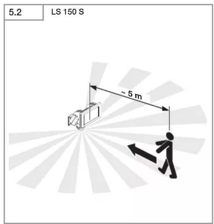
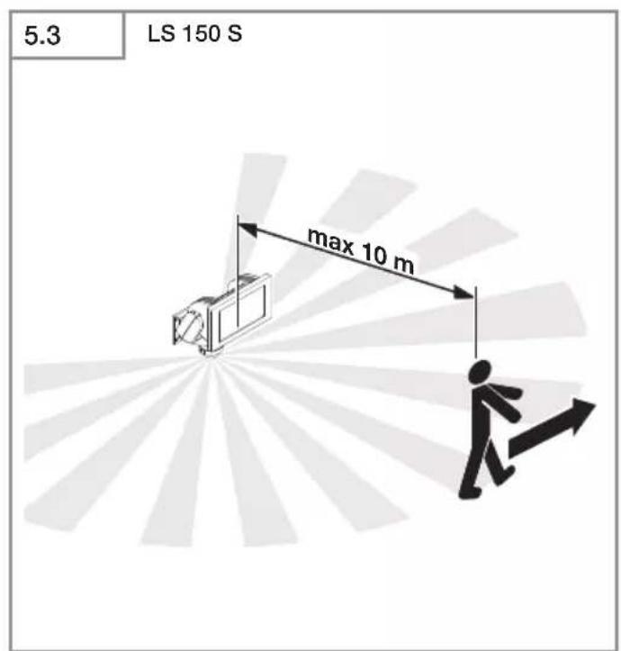
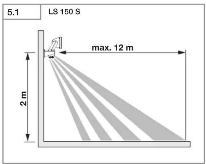
- The most reliable way of detecting motion is to install the unit with the sensor aimed across the direction in which a person would walk.
- Reach is restricted when the unit is approached head on.
- Obstacles (e.g. trees, walls etc.) interrupt the line of sensor vision.
- Heat radiation is not detected through obstacles (e.g. walls or panes of glass), the sensor is not triggered.
- Sudden fluctuations in the temperature from changes in weather are not distinguished sources of heat.
Models
Package contents (Fig. 3.1, Fig. 3.2)
Floodlight adjustment range (Fig. 3.3, Fig. 3.4, Fig. 6.7)
Sensor unit swivelling range (Fig. 3.3, Fig. 6.6)
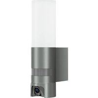
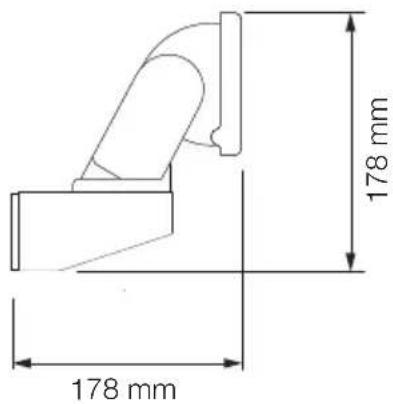
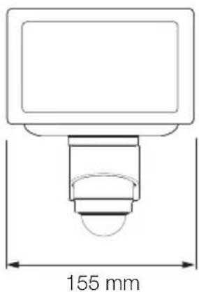
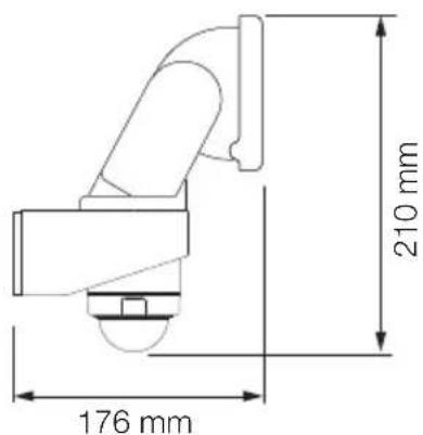
LS 150 S product dimensions (Fig. 3.5)
LS 150 product dimensions (Fig. 3.6)
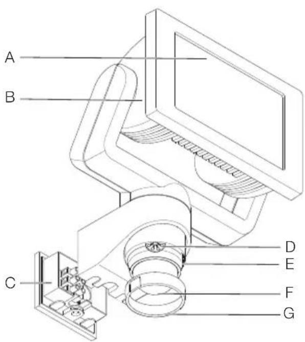
LS 150 S product components (Fig. 3.7)
A LED panel
B Enclosure
C Wall mount
D Time setting
E Twilight setting
F Sensor unit
G Ring cover
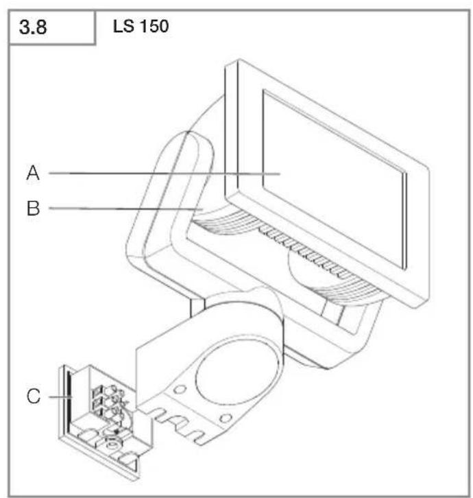
LS 150 S product components (Fig. 3.8)
A LED panel
B Enclosure
C Wall mount
Technical specifications
-Dimensions (H× W× D)
$$
L S 1 5 0 S: 2 1 0 \times 1 5 5 \times 1 7 6 m m
$$
$$
L S 1 5 0: 1 7 8 \times 1 5 7 \times 1 7 8 m m
$$
-Power consumption ( P_on ): 14.70 W
-Luminous flux (120°): 1,375 lm
-Half-way angle: 51^
-Efficiency: 94 lm/W
-Power supply: 220-240 V, 50/60 Hz
- Colour temperature: 4,000 K (neutral white)
–Average rated life expectancy:
$$
L 7 0 B 5 0 \text { at } 2 5 ^ {\circ} \mathrm{C}: 3 6, 0 0 0 \text { hours }
$$
-Colour rendering index: R_g = 80
- Colour consistency SDCM: starting value 6
-Luminous intensity distribution:
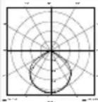
– Area illuminated to the front: approx. 240 cm ^2
– Sensor technology (S onlyS): passive infrared
-Sensor on standby (P_sb) (S only): 0.50 W
-Angle of coverage (S only):
$$
2 4 0 ^ {\circ} \text { with } 1 8 0 ^ {\circ} \text { angle of aperture }
$$
- Sensor unit swivelling range (S only): ± 80^
-Floodlight adjusting range:
$$
\text { turns through } \pm 4 0 ^ {\circ}
$$
$$
\text { vertically } + 1 1 0 ^ {\circ} \text { to } - 4 0 ^ {\circ}
$$
-Time setting (S only): 10 s - 15 min
- Twilight setting (S only): 2 - 1,000 lux
- Reach (S only): max. 12 m
- IP rating: IP44
- Protection class:
- Impact resistance: IK 03
- Ambient temperature: -10 °C to +30 °C
- Energy efficiency class: this product contains
an energy efficiency class "E" light source
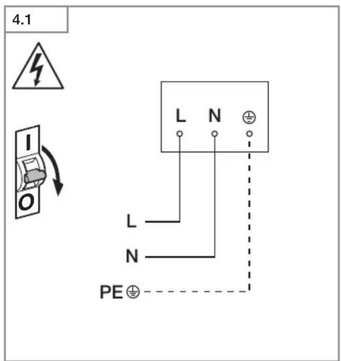
4. Electrical installation
Connection
The supply lead is a 2 or 3-core cable:
L = phase conductor (usually black, brown or grey)
N = neutral conductor (usually blue)
PE = protective-earth conductor (green / yellow)
Note:
The protective-earth conductor need not be connected for this product.
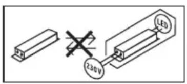
Wiring diagram (Fig. 4.1)
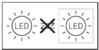
The light source of this LED floodlight cannot be replaced. If the light source needs to be replaced (e.g. at the end of its service life), the complete LED floodlight must be replaced.
5. Installation
Hazard from electrical power!
Touching live parts can result in electrical shock, burns or death.
- Switch OFF power and interrupt power supply.
- Using a voltage tester, check to make sure the light is disconnected from the power supply.
- Make sure power supply remains interrupted.
Risk of damage to property!
Mixing up connection leads may produce a short circuit.
- Identify connection leads.
• Re-connect connection leads.
Preparing for installation
- Check all components for damage. Do not use the product if it is damaged.
- Select an appropriate site to install the product.
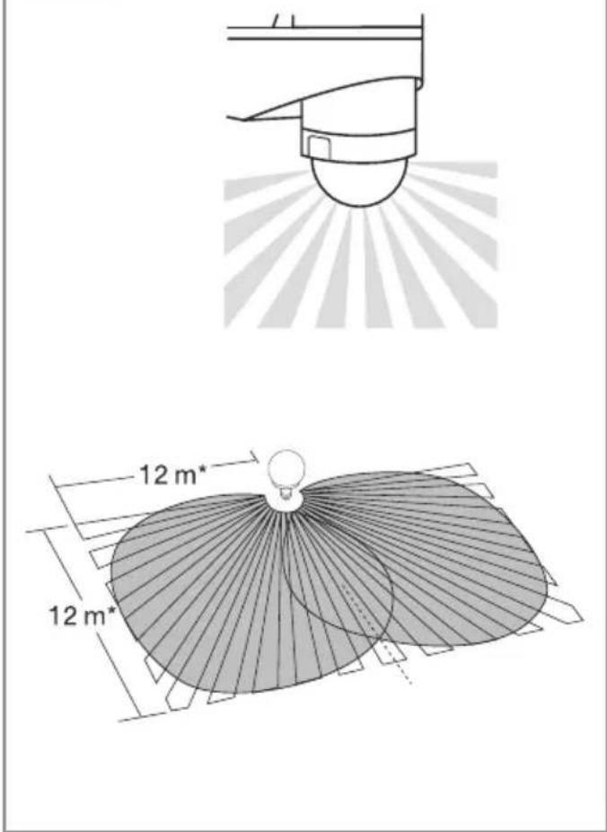
- Take reach into consideration. (Fig. 5.1)
- Take reach and motion detection into consideration. (Fig. 5.2, Fig. 5.3)
- Vibration-free.
- No obstacles in detection zone.
- Not in explosive atmospheres.
- Not on normally flammable surfaces.
- Do not look into the LED light from a short distance (< 20 cm).
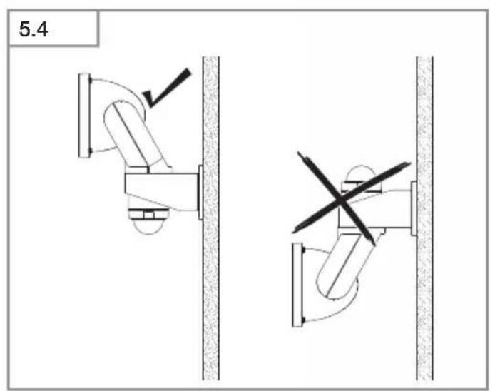
- Installing LED floodlight in horizontal position (± 15°).
- Correctly aiming LED floodlight. (Fig. 5.4)
Mounting procedure
- Check to make sure the power supply is switched OFF. (Fig. 4.1)
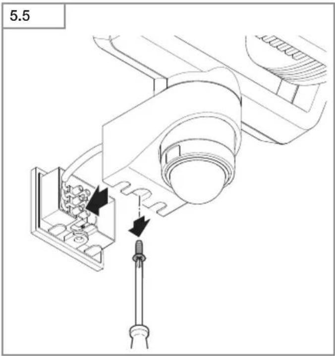
- Unscrew retaining screw. (Fig. 5.5)
- Detach enclosure from wall mount. (Fig. 5.5)
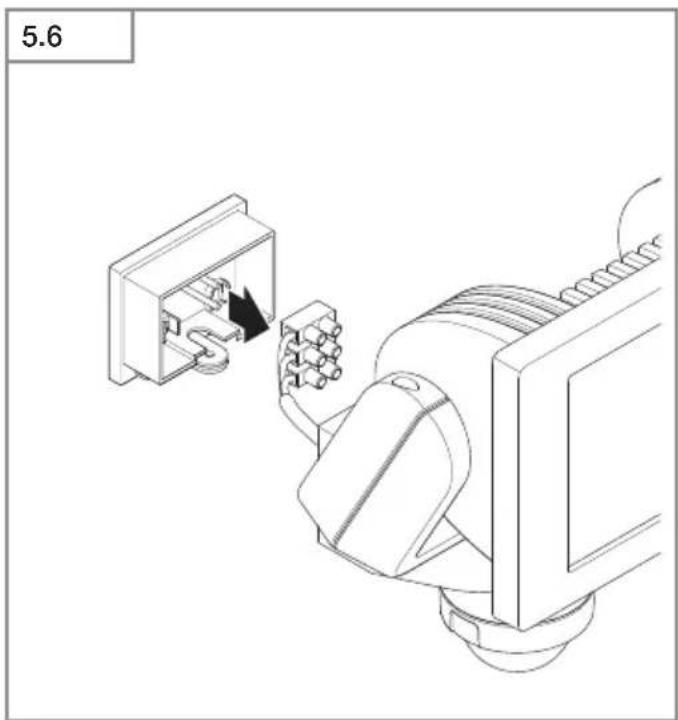
- Detach plug-in terminal from wall mount. (Fig. 5.6)
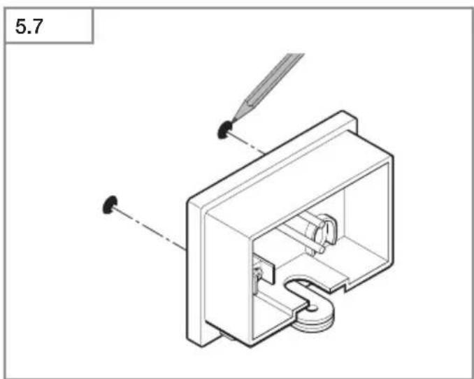
• Mark drill holes. (Fig. 5.7)
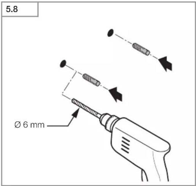
- Drill holes and fit ground plugs. (Fig. 5.8)
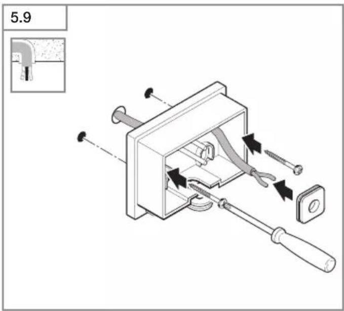
- Pierce web. Fit sealing plug, feed cable through (concealed power supply lead). (Fig. 5.9)
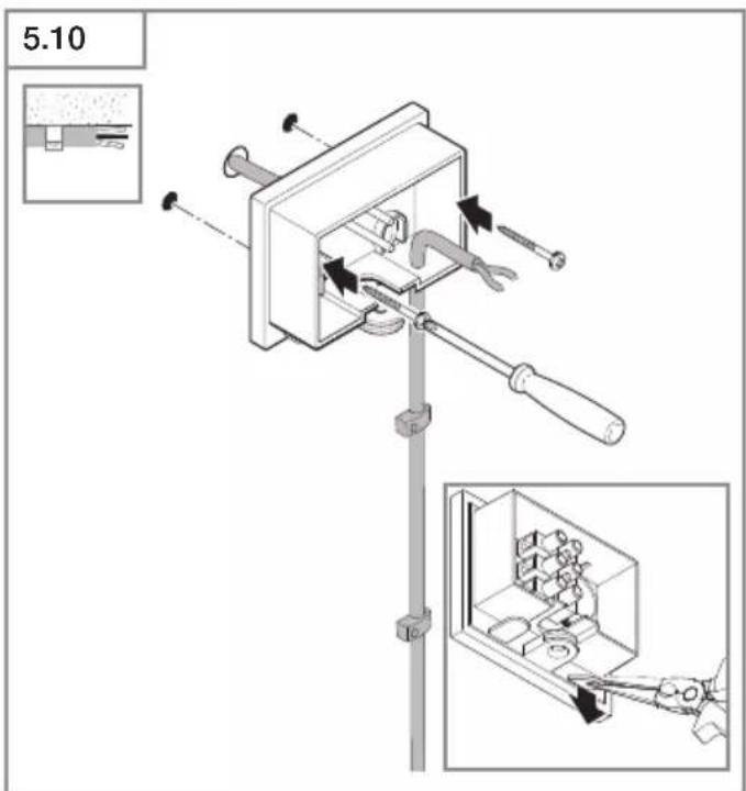
- Break off one of the two lugs. Pierce web. Feel through cable (surface-mounted power supply lead). (Fig. 5.10)
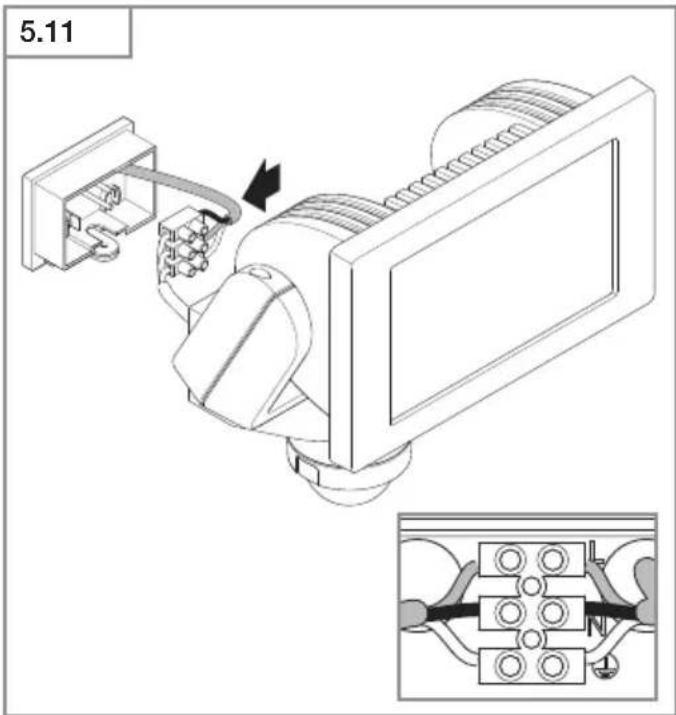
- Connect conductors. (Fig. 5.11)
- Connect plug-in terminal. (Fig. 5.11)
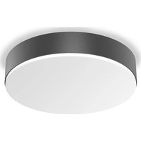
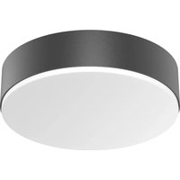
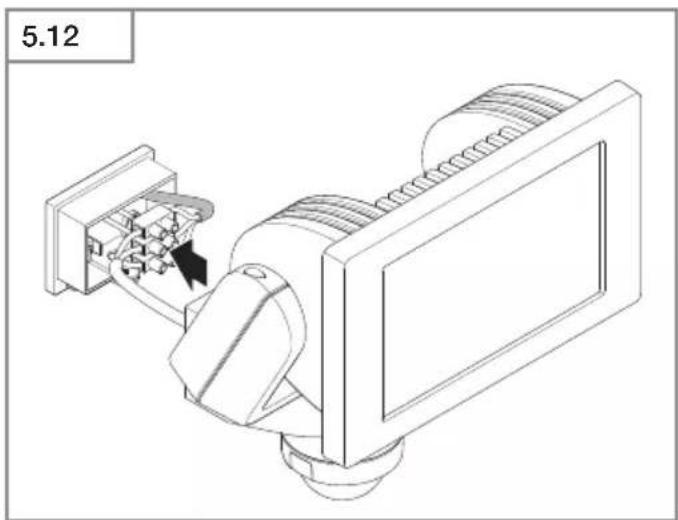
- Fit enclosure onto wall mount. (Fig. 5.12)
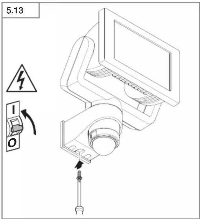
- Screw in locking screw. (Fig. 5.13)
- Switch ON power supply. (Fig. 5.13)
- Make settings.
→“6. Function”
6. Function
Factory settings (S only)
Time setting (E): 10 seconds
Twilight setting (F): 1,000 lux, (daytime mode)
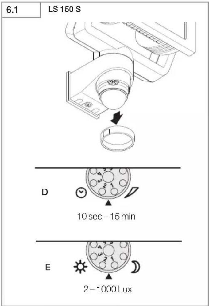
All functions can be set after removing the ring cover.
Time setting (S only) (Fig. 6.1 / D)
The time you want the LED floodlight to stay on for (main light) is infinitely adjustable from approx. 10 seconds to a maximum of 15 minutes. Any movement detected before this time elapses will restart the timer.
- Control dial set to + = longest time, approx. 15 minutes
- Control dial set to - = approx. 10 seconds
Twilight setting (S only) (Fig. 6.1 / E)
The LED floodlight's chosen response threshold can be infinitely varied from approx. 2 to 1,000 lux.
- Control dial set to ⚙ = daylight operation (independent of ambient brightness)
- Control dial set to = night-time operation (approx. 2 lux)
The control dial must be turned to ⚙ when adjusting the detection zone and performing the functional test in daylight.
Note:
When setting the detection zone, it is recommended to
- select the shortest time.
- twilight setting.
Note:
After the LED floodlight switches OFF, it takes approx. 1 second before it is able to start detecting movement again. The LED floodlight will only switch ON in response to movement once this period has elapsed.
Self-test (S only)
When putting the floodlight into operation, the electronic system carries out a self-test which lasts for approx. 1 minute. Once this has been completed, the sensor is active.
Reach setting / adjustment (S only)
The detection zone can be optimised to suit requirements.
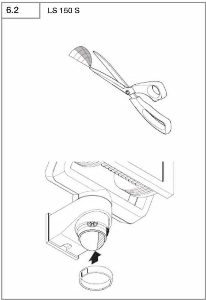
Film shroud (S only) (Fig. 6.2)
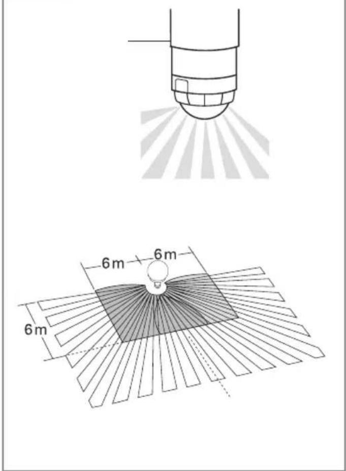
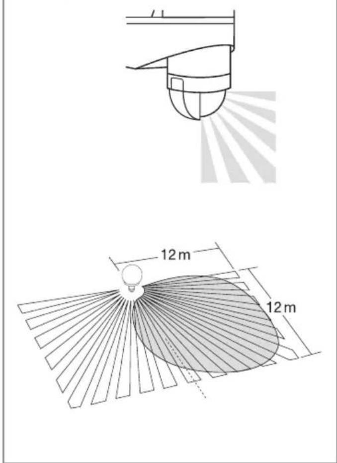
The film shroud can be used for masking out any number of lens segments to limit reach as required. Inadvertent triggering is ruled out or the sensor can be targeted to watch over danger spots. (Fig. 6.3, Fig. 6.4, Fig. 6.5)
- The shrouds can be cut along the grooved vertical and horizontal divisions. (Fig. 6.2).
- Detach ring cover.
- Clip in shrouds at the top of the sensor lens.
- Fitting the ring cover fixes the shrouds firmly in place. (Fig. 6.2)
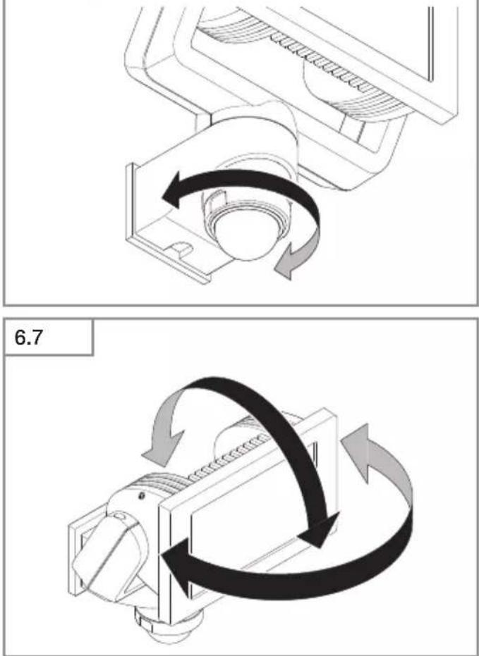
Sensor unit (S only)
The sensor housing can also be turned through ± 80^ for precision targeting.
- Turning the sensor unit horizontally through ± 80^ . (Fig. 6.6)
Floodlight adjustment range (Fig. 6.7)
7. Operation
The LED floodlight is not suitable for burglar alarm systems as it is not tamperproof in the manner prescribed for such systems. Weather conditions may affect the way the LED floodlight works. Strong gusts of wind, snow, rain and hail may cause the light to come ON when it is not wanted because the sensor is unable to distinguish between sudden changes in temperature and sources of heat.
8. Cleaning and Maintenance
Hazard from electrical power!
Contact between water and live parts can result in electrical shock, burns or death.
- Only clean tool in a dry state.
Risk of damage to property!
Using the wrong detergent can damage the light.
- Clean unit with a moist cloth without detergent.
Important note: the control gear cannot be replaced.
9. Troubleshooting
Unit without power.
- Fuse not switched ON or faulty.
- Switch ON fuse.
- Change faulty fuse.
- Break in wiring.
- Switch ON mains switch.
- Check wiring with voltage tester.
– Short circuit in mains power supply lead.
- Check connections.
Unit does not switch ON.
– Wrong twilight setting selected.
• Re-set brightness response threshold
- Mains switch OFF.
- Switch ON mains switch.
- Fuse not switched ON or faulty.
- Switch ON fuse.
- Change faulty fuse.
– Detection zone too small or incorrect.
- Check and adjust detection zone.
– Light source faulty.
- The light source cannot be changed. Completely replace unit.
Unit does not switch OFF.
- Continued movement within the detection zone.
- Check detection zone.
- If necessary, limit or change detection zone.
Unit switches ON when it should not
- Movement within the detection zone, e.g. from animals, trees or cars.
- Check detection zone.
- If necessary, limit or change detection zone.
- Unit is moving as a result of gusts of wind or precipitation.
- Mount unit on a firm surface.
10. Disposal
Electrical and electronic equipment, accessories and packaging must be recycled in an environmentally compatible manner.
not dispose of electrical and electronic equipment as domestic waste!
EU countries only:
Under the current European Directive on Waste Electrical and Electronic Equipment and its implementation in national law, electrical and electronic equipment no longer suitable for use must be collected separately and recycled in an environmentally compatible manner.
STEINEL GmbH hereby declares that the LS 150 S / LS 150 conforms to Directive 2014/53/EU.
The full wording of the EU Declaration of Conformity is available for downloading from the following Internet address: www.steinel.de
12. Manufacturer's warranty
Manufacturer's warranty of STEINEL GmbH, Diesel strasse 80-84, DE-33442 Herzebrock-Clarholz, Germany
All STEINEL products meet the highest quality standards. For this reason, we, the manufacturer, are pleased to provide you, the consumer, with a warranty under the following terms and conditions:
The warranty covers the absence of deficiencies which are proven to be the result of a material defect or fault in manufacturing and which are reported to us immediately after detection and within the warranty period. The warranty shall apply to all STEINEL products sold and used in Germany – excluding STEINEL Professional products.
You can opt for warranty cover in the form of repair or replacement which will be provided free of charge (if applicable, in the form of a successor model of the same or higher quality) or in the form of a credit note.
The warranty period for the STEINEL product you have purchased is 3 years (5 years for products from the XLED home range) in each case from the date on which the product was purchased.
We shall bear the shipping costs but not the transport risks involved in return shipment.
Statutory rights accruing from defects, gratuitousness
The warranty cover described here shall be applicable in addition to the statutory rights of warranty – including special consumer protection provisions – and shall not restrict or replace them. Exercising your statutory rights in the event of defects is gratuitous.
Exemptions from the warranty
All replaceable lamps are expressly excluded from this warranty. In addition to this, the warranty shall not cover:
-any wear resulting from use or any other natural wear of product parts or any deficiencies in the STEINEL product that are attributable to wear caused by use or other natural wear,
-any improper or non-intended use of the product or any failure to observe the operating instructions,
–any unauthorised additions, alterations or other modifications to the product or any deficiencies attributable to the use of accessory,
-supplementary or replacement parts which are not genuine STEINEL parts,
–any maintenance or care of products that is not carried out in accordance with the operating instructions,
-any attachment or installation that is not in accordance with STEINEL's installation instructions, -any damage or loss occurring in transit.
Application of German law
The warranty shall be governed by German law excluding the United Nations Convention concerning the International Sale of Goods (CISG).
Making claims
If you wish to make a warranty claim, please send your product complete and carriage paid with the original receipt of purchase, which must show the date of purchase and product designation, either to your retailer or directly to us at STEINEL (UK) Ltd. – 25 Manasty Road, Axis Park, Orton Southgate, GB- Peterborough Cambs PE2 6UP United Kingdom.
For this reason, we recommend that you keep your receipt of purchase in a safe place until the warranty period expires.
FR
-Dimensions (H × I × P):
$$
L S 1 5 0 S: 2 1 0 \times 1 5 5 \times 1 7 6 m m
$$
$$
L S 1 5 0: 1 7 8 \times 1 5 7 \times 1 7 8 m m
$$
-Dimensioni (A x L x P):
LS 150 S: 210 × 155 × 176 mm
LS 150: 178 × 157 × 178 mm
-Potenza assorbita (P _on ): 14,70 W
-Flusso luminoso (120°): 1.375 lm
in verticale + 110°--40°
-Méretek (Ma × Sz × Mé):
$$
L S 1 5 0 S: 2 1 0 \times 1 5 5 \times 1 7 6 m m
$$
$$
L S 1 5 0: 1 7 8 \times 1 5 7 \times 1 7 8 m m
$$
(Obr. 3.3, Obr. 6.6)
$$
R _ {\mathrm{a}} = 8 0
$$
5. Montaaž
natural_image
World map silhouette in grayscale, showing continents and oceans without any text or labels
www.steinel.de/contact