HM100MP - Saw SCHEPPACH - Free user manual and instructions
Find the device manual for free HM100MP SCHEPPACH in PDF.
| Feature | Description |
|---|---|
| Saw type | Panel saw |
| Power | 2000 W |
| Blade diameter | 315 mm |
| Rotation speed | 4500 rpm |
| Maximum cutting capacity | At 90°: 100 mm, At 45°: 60 mm |
| Weight | 45 kg |
| Dimensions | 1200 x 800 x 1100 mm |
| Usage | Ideal for precise cuts of wood, panels, and similar materials. |
| Maintenance | Regularly check the blade condition and lubricate moving parts. |
| Safety | Wear safety glasses and gloves. Do not remove safety devices. |
| General information | 2-year warranty, after-sales service available. |
Frequently Asked Questions - HM100MP SCHEPPACH
Download the instructions for your Saw in PDF format for free! Find your manual HM100MP - SCHEPPACH and take your electronic device back in hand. On this page are published all the documents necessary for the use of your device. HM100MP by SCHEPPACH.
USER MANUAL HM100MP SCHEPPACH
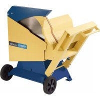
Sliding cross cut mitre saw Translation of original instruction manual 20-31
3. Scope of delivery 22
7. Before starting the equipment 27
8. Attachment and operation 27
13. Disposal and recycling 30
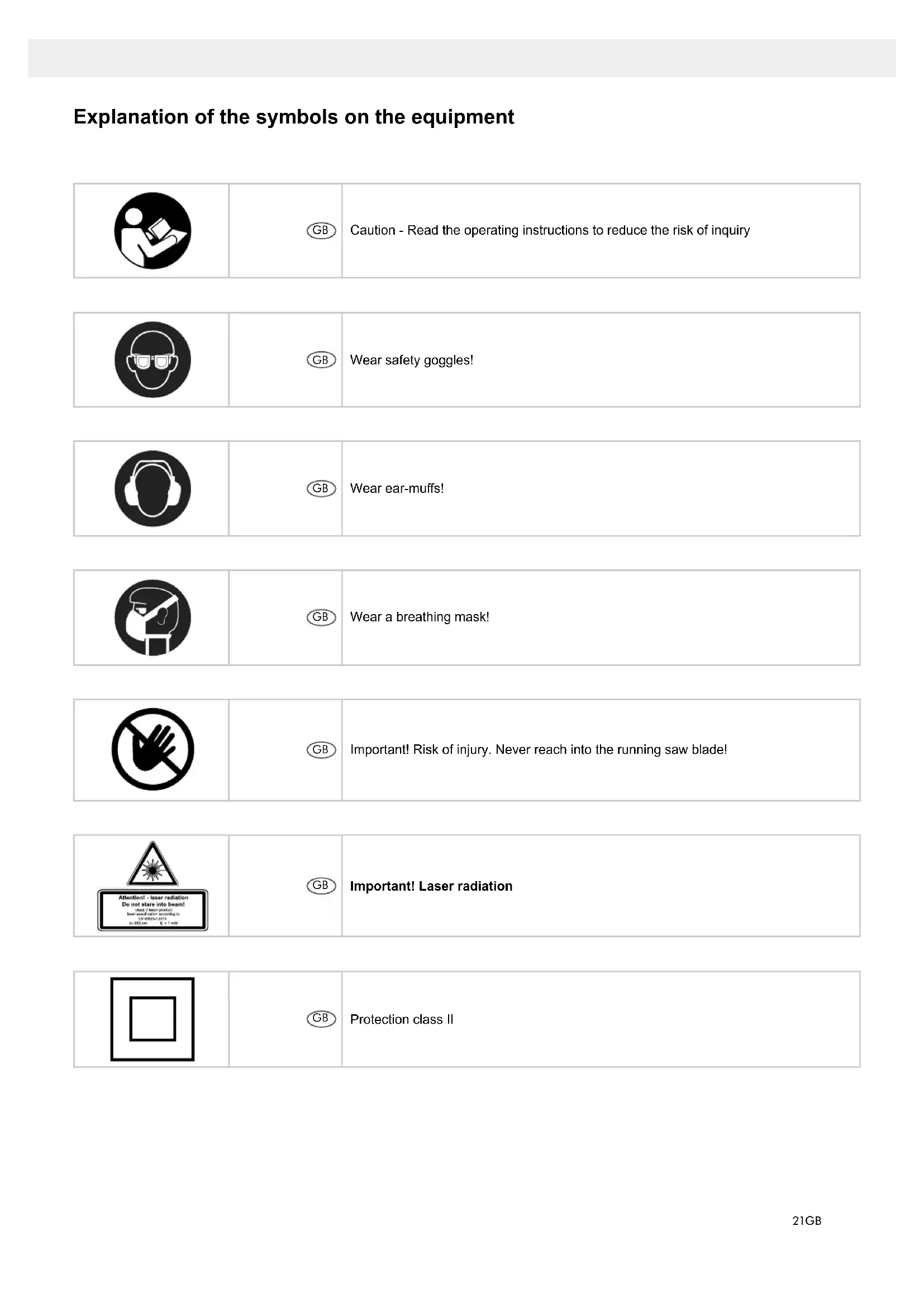
Caution - Read the operating instructions to reduce the risk of inquiry
Wear safety goggles!
Important! Risk of injury. Never reach into the running saw blade!
Important! Laser radiation
Wear a breathing mask! Explanation of the symbols on the equipment22 GB
MANUFACTURER: scheppach Fabrikation von Holzbearbeitungsmaschinen GmbH Günzburger Straße 69 D-89335 Ichenhausen DEAR CUSTOMER, We hope your new tool brings you much enjoyment and success. NOTE: According to the applicable product liability laws, the manufacturer of the device does not assume liability for damages to the product or damages caused by the product that occurs due to:
- Non-compliance of the operating instructions,
- Repairs by third parties, not by authorized service technicians,
- Installation and replacement of non-original spare parts,
- Application other than specied,
- A breakdown of the electrical system that occurs due to the non-compliance of the electric regu- lations and VDE regulations 0100, DIN 57113 / VDE0113. WE RECOMMEND: Read through the complete text in the operating in- structions before installing and commissioning the device. The operating instructions are intended to help the user to become familiar with the machine and take advantage of its application possibilities in accordance with the recommendations. The operat- ing instructions contain important information on how to operate the machine safely, professionally and economically, how to avoid danger, costly repairs, re- duce downtimes and how to increase reliability and service life of the machine. In addition to the safety regulations in the operating instructions, you have to meet the applicable regula- tions that apply for the operation of the machine in your country. Keep the operating instructions pack- age with the machine at all times and store it in a plastic cover to protect it from dirt and moisture. Read the instruction manual each time before op- erating the machine and carefully follow its informa- tion. The machine can only be operated by persons who were instructed concerning the operation of the machine and who are informed about the associated dangers. The minimum age requirement must be complied with. In addition to the safety notices contained in this operating manual and the particular instructions for your country, the generally recognised technical reg- ulations for the operation of identical devices must be complied with. We accept no liability for damage or accidents which arise due to non-observance of these instructions and the safety information.
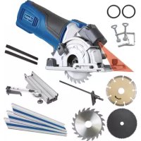
6. Movable blade guard
9. Workpiece support
10. Locking screw for workpiece support
29. Set screw for moveable stop rail
30. Adjustment screw (90°)
31. Adjustment screw (45°)
36. Battery compartment
37. Battery compartment cover
42. Switch for switching speeds
a) 90° stop angle (not supplied) b) 45° stop angle (not supplied) c) Allen key, 6 mm
3. Scope of delivery
- Open the packaging and remove the device care- fully.
- Remove the packaging material as well as the packaging and transport bracing (if available).23GB
- Check that the delivery is complete.
- Check the device and accessory parts for trans- port damage.
- If possible, store the packaging until the warranty period has expired. ATTENTION The device and packaging materials are not toys! Children must not be allowed to play with plas- tic bags, lm and small parts! There is a risk of swallowing and suocation!
- Drag, crosscut and mitre Saw
- 1 x Clamping device (8)
- 2 x Workpiece support (9)
The trim, mitre and bevel saw is used to mitre wood, materials similar to wood, plastics and non-ferrous metals, with the exception of magnesium and alloys containing magnesium, according to the machine size. Warning! The supplied saw blade is only intended for the sawing of wood! Do not use this blade for the sawing of plastic! The equipment is to be used only for its prescribed purpose. Any other use is deemed to be a case of misuse. The user / operator and not the manufac- turer will be liable for any damage or injuries of any kind caused as a result of this. The equipment is to be operated only with suitable saw blades. It is prohibited to use any type of cut- ting-o wheel. To use the equipment properly you must also ob- serve the safety information, the assembly instruc- tions and the operating instructions to be found in this manual. All persons who use and service the equipment have to be acquainted with this manual and must be in- formed about the equipment’s potential hazards. It is also imperative to observe the accident prevention regulations in force in your area. The same applies for the general rules of health and safety at work. The manufacturer will not be liable for any changes made to the equipment nor for any damage result- ing from such changes. Even when the equipment is used as prescribed it is still impossible to eliminate certain residual risk factors. The following hazards may arise in connection with the machine’s construc- tion and design:
- Contact with the saw blade in the uncovered saw zone.
- Reaching into the running saw blade (cut injuries).
- Kick-back of workpieces and parts of workpieces.
- Saw blade fracturing.
- Catapulting of faulty carbide tips from the saw blade.
- Damage to hearing if ear-mus are not used as necessary.
- Harmful emissions of wood dust when used in closed rooms. Please note that our equipment has not been de- signed for use in commercial, trade or industri- al applications. Our warranty will be voided if the equipment is used in commercial, trade or industrial businesses or for equivalent purposes.
5. Safety information
Attention! The following basic safety measures must be observed when using electric tools for protection against electric shock, and the risk of injury and re. Read all these notices before using the electric tool and keep the safety instructions for later reference. Safe work 1 Keep the work area orderly – Disorder in the work area can lead to accidents. 2 Take environmental inuences into account – Do not expose electric tools to rain. – Do not use electric tools in a damp or wet en- vironment. – Make sure that the work area is well-illuminated. – Do not use electric tools where there is a risk of re or explosion. 3 Protect yourself from electric shock – Avoid physical contact with earthed parts (e.g. pipes, radiators, electric ranges, cooling units). 4 Keep children away – Do not allow other persons to touch the equip- ment or cable, keep them away from your work area. 5 Securely store unused electric tools – Unused electric tools should be stored in a dry, elevated or closed location out of the reach of children. 6 Do not overload your electric tool – They work better and more safely in the speci- ed output range. 7 Use the correct electric tool – Do not use low-output electric tools for heavy work. – Do not use the electric tool for purposes for which it is not intended. For example, do not use handheld circular saws for the cutting of branches or logs. – Do not use the electric tool to cut rewood. 8 Wear suitable clothing – Do not wear wide clothing or jewellery, which can become entangled in moving parts. – When working outdoors, anti-slip footwear is recommended. – Tie long hair back in a hair net. 9 Use protective equipment – Wear protective goggles. – Wear a mask when carrying out dust-creating work.24 GB 10 Connect the dust extraction device if you will be processing wood, materials similar to wood, or plastics. – ATTENTION! The dust extractor must not be connected when processing metals. Risk of re and explosion due to hot swarf or ying sparks! When processing metals, also remove the dust bag (21). – If connections for dust extraction and a collect- ing device are present, make sure that they are connected and used properly. – When processing wood, materials similar to wood, and plastics. operation in enclosed spac- es is only permitted with the use of a suitable extraction system. 11 Do not use the cable for purposes for which it is not intended – Do not use the cable to pull the plug out of the outlet. Protect the cable from heat, oil and sharp edges. 12 Secure the workpiece – Use the clamping devices or a vice to hold the workpiece in place. In this manner, it is held more securely than with your hand. – An additional support is necessary for long workpieces (table, trestle, etc.) in order to pre- vent the machine from tipping over. – Always press the workpiece rmly against the working plate and stop in order to prevent bouncing and twisting of the workpiece. 13 Avoid abnormal posture – Make sure that you have secure footing and always maintain your balance. – Avoid awkward hand positions in which a sud- den slip could cause one or both hands to come into contact with the saw blade. 14 Take care of your tools – Keep cutting tools sharp and clean in order to be able to work better and more safely. – Follow the instructions for lubrication and for tool replacement. – Check the connection cable of the electric tool regularly and have it replaced by a recognised specialist when damaged. – Check extension cables regularly and replace them when damaged. – Keep the handle dry, clean and free of oil and grease. 15 Pull the plug out of the outlet – Never remove loose splinters, chips or jammed wood pieces from the running saw blade. – During non-use of the electric tool or prior to maintenance and when replacing tools such as saw blades, bits, milling heads. – When the saw blade is blocked due to abnormal feed force during cutting, turn the machine o and disconnect it from power supply. Remove the work piece and ensure that the saw blade runs free. Turn the machine on and start new cutting operation with reduced feed force. 16 Do not leave a tool key inserted – Before switching on, make sure that keys and adjusting tools are removed. 17 Avoid inadvertent starting – Make sure that the switch is switched o when plugging the plug into an outlet. 18 Use extension cables for outdoors – Only use approved and appropriately identied extension cables for use outdoors. – Only use cable reels in the unrolled state. 19 Remain attentive – Pay attention to what you are doing. Remain sensible when working. Do not use the electric tool when you are distracted. 20 Check the electric tool for potential damage – Protective devices and other parts must be carefully inspected to ensure that they are fault- free and function as intended prior to continued use of the electric tool. – Check whether the moving parts function fault- lessly and do not jam or whether parts are dam- aged. All parts must be correctly mounted and all conditions must be fullled to ensure fault- free operation of the electric tool. – The moving protective hood may not be xed in the open position. – Damaged protective devices and parts must be properly repaired or replaced by a recognised workshop, insofar as nothing dierent is speci- ed in the operating manual. – Damaged switches must be replaced at a cus- tomer service workshop. – Do not use any faulty or damaged connection cables. – Do not use any electric tool on which the switch cannot be switched on and o. 21 ATTENTION! – Exercise elevated caution for double mitre cuts. 22 ATTENTION! – The use of other insertion tools and other ac- cessories can entail a risk of injury. 23 Have your electric tool repaired by a qualied electrician – This electric tool conforms to the applicable safety regulations. Repairs may only be per- formed by an electrician using original spare parts. Otherwise accidents can occur.
ADDITIONAL SAFETY INSTRUCTIONS
1 Safety precautions – Warning! Do not use damaged or deformed saw blades. – Replace a worn table insert. – Only use saw blades recommended by the manufacturer which conform to EN 847-1. – Make sure that a suitable saw blade for the material to be cut is selected.25GB – Wear suitable personal protective equipment. This includes: – Hearing protection to avoid the risk of be- coming hearing impaired, – Respiratory protection to avoid the risk of inhaling harmful dust, – Wear gloves when handling saw blades and rough materials. Carry saw blades in a con- tainer whenever practical. – Wear goggles. Sparks generated during work or splinters, chippings and dust coming from the device can lead to loss of eyesight. – Connect a dust collecting device to the electric tool when sawing wood. The emission of dust is inuenced, among other things, by the type of material to be processed, the signicance of local separation (collection or source) and the correct setting of the hood/guide plates/guides. – Do not use saw blades made of high-speed alloy steel (HSS steel). 2 Maintenance and repair – Pull out the mains plug for any adjustment or repair tasks. – The generation of noise is inuenced by vari- ous factors, including the characteristics of saw blades, condition of saw blade and electric tool. Use saw blades which were designed for re- duced noise development, insofar as possible. Maintain the electric tool and tool attachments regularly and if necessary, initiate repairs in order to reduce noise. – Report faults on the electric tool, protective devices or the tool attachment to the person responsible for safety as soon as they are dis- covered. 3 Safe work – Only use saw blades for which the maximum permissible speed is not lower than the maxi- mum spindle speed of table saws and which are suitable for the material to be cut. – Make sure that the saw blade does not touch the rotary table in any position by pulling out the mains plug and rotating the saw blade by hand in the 45° and 90° position. If necessary, readjust the saw head. – When transporting the electric tool, only use the transport devices. Never use the protective devices for handling or transport. – Make sure that the lower part of the saw blade is covered during transport, e.g. by the protective device. – Be sure to only use spacers and spindle rings specied by the manufacturer as suitable for the intended purpose. – The oor around the machine must be level, clean and free of loose particles, such as chips and cutting residues. – Do not remove any cutting residues or other parts of workpieces from the cutting zone while the machine is running and the saw unit is not at rest. – Make sure that the machine is always secured on a workbench or a table if at all possible. – Support long workpieces (e.g. with a roller ta- ble) to prevent them sagging at the end of a cut. Warning! This electric tool generates an electro- magnetic eld during operation. This eld can impair active or passive medical implants under certain conditions. In order to prevent the risk of serious or deadly injuries, we recommend that persons with medical implants consult with their physician and the manufacturer of the medical implant prior to operat- ing the electric tool.
SAFETY INSTRUCTIONS FOR THE HANDLING
1 Only use insertion tools if you have mastered their use. 2 Observe the maximum speed. The maximum speed specied on the insertion tool may not be exceeded. If specied, observe the speed range. 3 Observe the motor / saw blade direction of rota- tion. 4 Do not use any insertion tools with cracks. Sort out cracked insertion tools. Repairs are not per- mitted. 5 Clean grease, oil and water o of the clamping surfaces. 6 Do not use any loose reducing rings or bushes for the reducing of holes on saw blades. 7 Make sure that xed reducer rings for securing the insertion tool have the same diameter and have at least 1/3 of the cutting diameter. 8 Make sure that xed reducer rings are parallel to each other. 9 Handle insertion tool with caution. They are ide- ally stored in the originally package or special containers. Wear protective gloves in order to im- prove grip and to further reduce the risk of injury. 10 Prior to the use of insertion tools, make sure that all protective devices are properly fastened. 11 Prior to use, make sure that the insertion tool meets the technical requirements of this electric tool and is properly fastened. 12 Only use the supplied saw blade for sawing oper- ations in wood, materials similar to wood, plastics and non-ferrous metals (except for magnesium and alloys containing magnesium). Attention: Laser radiation Do not stare into the beam Class 2 laser26 GB Protect yourself and you environment from ac- cidents using suitable precautionary measures!
- Do not look directly into the laser beam with un- protected eyes.
- Never look into the path of the beam.
- Never point the laser beam towards reecting sur- faces and persons or animals. Even a laser beam with a low output can cause damage to the eyes.
- Caution - methods other than those specied here can result in dangerous radiation exposure.
- Never open the laser module. Unexpected expo- sure to the beam can occur.
- If the mitre saw is not used for an extended period of time, the batteries should be removed.
- The laser may not be replaced with a dierent type of laser.
- Repairs of the laser may only be carried out by the laser manufacturer or an authorised representative. Safety instructions for handling batteries 1 Always make sure that the batteries are inserted with the correct polarity (+ and –), as indicated on the battery. 2 Do not short-circuit batteries. 3 Do not charge non-rechargeable batteries. 4 Do not overcharge batteries! 5 Do not mix old and new batteries or batteries of dierent types or manufacturers! Replace an entire set of batteries at the same time. 6 Immediately remove used batteries from the de- vice and dispose of them properly! 7 Do not allow batteries to heat up! 8 Do not weld or solder directly on batteries! 9 Do not dismantle batteries! 10 Do not allow batteries to deform! 11 Do not throw batteries into re! 12 Keep batteries out of the reach of children. 13 Do not allow children to replace batteries without supervision! 14 Do not keep batteries near re, ovens or other sources of heat. Do not use batteries in direct sunlight or store them in vehicles in hot weather. 15 Keep unused batteries in the original packaging and keep them away from metal objects. Do not mix unpacked batteries or toss them together! This can lead to a short-circuit of the battery and thus damage, burns or even the risk of re. 16 Remove batteries from the equipment when it will not be used for an extended period of time, unless it is for emergencies! 17 NEVER handle batteries that have leaked with- out appropriate protection. If the leaked uid comes into contact with your skin, the skin in this area should be rinsed o under running wa- ter immediately. Always prevent the uid from coming into contact with the eyes and mouth. In the event of contact, please seek immediate medical attention. 18 Clean the battery contacts and corresponding contacts in the device prior to inserting the bat- teries:
- S6, continuous operation periodic duty. Identical duty cycles with a period at load fol- lowed by a period at no load. Running time 5 minutes; duty cycle is 20% of the running time. The work piece must have a minimum height of 3mm and a minimum width of 10 mm. Make sure that the workpiece is always secured with the clamping device. Noise and vibration Total vibration values determined in accordance with EN 61029. Sound pressure level L
3 dB Wear hearing protection. The eects of noise can cause a loss of hearing. Total vibration values (vector sum - three directions) determined in accordance with EN 61029. Residual risks The machine has been built according to the state of the art and the recognised technical safety requirements. However, individual residu- al risks can arise during operation.
- Health hazard due to electrical power, with the use of improper electrical connection cables.27GB
- Furthermore, despite all precautions having been met, some non-obvious residual risks may still remain.
- Residual risks can be minimised if the „safety in- structions“ and the „Proper use“ are observed along with the whole of the operating instructions.
- Do not load the machine unnecessarily: excessive pressure when sawing will quickly damage the saw blade, which results in reduced output of the ma- chine in the processing and in cut precision.
- When cutting plastic material, please always use clamps: the parts which should be cut must always be xed between the clamps.
- Avoid accidental starting of the machine: the op- erating button may not be pressed when inserting the plug in an outlet.
- Use the tool that is recommended in this manual. In doing so, your mitre saw provides optimal per- formance.
- Hands may never enter the processing zone when the machine is in operation. Release the handle button and switch o the machine prior to any op- erations.
7. Before starting the equipment
- The equipment must be set up where it can stand securely, i.e. it should be bolted to a workbench, a universal base frame or similar.
- All covers and safety devices have to be properly tted before the equipment is switched on.
- It must be possible for the blade to run freely.
- When working with wood that has been processed before, watch out for foreign bodies such as nails or screws, etc.
- Before you press the ON/OFF switch check that the saw blade is tted correctly. Moving parts must run smoothly.
- Before you connect the equipment to the power supply make sure the data on the rating plate are identical to the mains data.
8. Attachment and operation
8.1 Attaching the saw (Fig. 1-6)
- To adjust the rotary table (16), push the locking lever (13) downwards and pull the lower indexed position lever (12) upwards with your index nger.
- Rotate the rotary table (16) and pointer (14) to the desired angle on the scale (15) and lock in place by folding up the locking lever (13).
- Pressing the machine head (5) lightly downwards and removing the locking bolt (24) from the motor bracket at the same time disengages the saw from the lowest position.
- Swing the machine head (5) up until the release lever (3) latches into place.
- It is possible to secure the clamping device (8) to the left or right on the stationary saw bench (17).
- Attach the workpiece supports (9) to the xed saw table (17) as shown in Figure 6a,b,c and push all the way through. Secure the shafts with the retain- ing springs to prevent them from slipping out ac- cidentally. The fasten in the desired position with the screw (10).
- It is possible to tilt the machine head (5) a max. 45° to the left by loosening the set screw (22).
8.2 Precision adjustment of the stop for crosscut
- No stop angle included.
- Lower the machine head (5) and secure using the locking bolt (24).
- Loosen the set screw (22).
- Position the angle stop (a) between the saw blade (7) and the rotary table (16).
- Slacken the counternut (d). Adjust the adjusting screw (30) until the angle between the saw blade (7) and rotary table (16) is 90°.
- Retighten the counternut (d) to secure this setting.
- Subsequently check the position of the angle indi- cator. If necessary loosen the pointer (20) using a Philips screwdriver, set to position 0° on the angle scale (19) and re-tighten the retaining screw.
8.3 Precision adjustment of the stop for mitre cut
- No stop angle included.
- Lower the machine head (5) and secure using the locking bolt (24).
- Fix the rotary table (16) in the 0° position.
- Loosen the set screw (22) and use the handle (1) to angle the machine head (5) 45° to the left.
- 45° - position angle stop (b) between the saw blade (7) and rotary table (16).
- Slacken the counternut (c). Adjust the adjusting screw (31) until the angle between the saw blade (7) and rotary table (16) is precisely 45°.
- Retighten the counternut (d) to secure this setting.
8.4 Cross cut 90° and turntable 0° (Fig.1,2,6,7)
In the case of cutting widths up to approx. 100 mm it is possible to x the traction function of the saw with the set screw (23) in the rear position. In this position the machine can be operated in cross cutting mode. If the cutting width is over 100 mm then it is neces- sary to ensure that the set screw (23) is loose and the machine head (5) can move. Attention! For 90° mitre cuts, the moveable stop rail (28) must be xed in the inner position.
- Open the set screw (29) on the moveable stop rail (28) and push the moveable stop rail (28) inwards.
- The moveable stop rail (28) must be locked in a position far enough from the inner position that the distance between the stop rail (28) and the saw blade (7) is no more than 5 mm.
- Before making the cut, check that no collision could occur between the stop rail (28) and the saw blade (7).
- Tighten the set screw (29) again. (2x 8.3 +8.4)
- Move the machine head (5) to its upper position.28 GB
- Use the handle (1) to push back the machine head (5) and x it in this position if required (dependent on the cutting width).
- Place the piece of wood to be cut at the stop rail (18) and on the turntable (16).
- Lock the material with the clamping device (8) on the xed saw table (16) to prevent the material from moving during the cutting operation.
- Push down the release lever (3) to release the ma- chine head (5).
- Press the ON/OFF switch (2) to start the motor.
- With the drag guide (23) xed in place: use the handle (1) to move the machine head (5) steadily and with light pressure downwards until the saw blade (7) has completely cut through the work piece.
- With the drag guide (23) not xed in place: pull the machine head (5) all the way to the front. Lower the handle (1) to the very bottom by applying steady and light downward pressure. Now push the machine head (5) slowly and steadily to the very back until the saw blade (7) has completely cut through the work piece.
- When the cutting operation is completed, move the machine head (5) back to its upper (home) position and release the ON/OFF button (2). Attention! The machine executes an upward stroke automatically due to the return spring, i.e. do not release the handle (1) after completing the cut; instead allow the machine head to move up- wards slowly whilst applying light counter pres- sure.
8.5 Cross cut 90° and turntable 0° - 45° (Fig. 1,6,7)
The crosscut saw can be used to make crosscuts of 0° -45° to the left and 0° -45° to the right in relation to the stop rail. Attention! For bevel cuts (inclined saw head), the moveable stop rail (28) must be xed in the outer position.
- Open the set screw (29) on the moveable stop rail (28) and push the moveable stop rail (28) out- wards.
- The moveable stop rail (28) must be locked in a position far enough from the inner position that the distance between the stop rail (28) and the saw blade (7) is no more than 5 mm.
- Before making the cut, check that no collision could occur between the stop rail (28) and the saw blade (7).
- Tighten the set screw (29) again. (2x 8.6 + 8.7)
- Use the handle (13) to adjust the rotary table (16) to the desired angle. The pointer (14) on the rota- ry table (16) must match the desired angle on the scale (15) on the xed saw table (17).
- Tilt the locking lever (13) back up again to x the rotary table (16) in place.
- Cut as described under section 8.3.
8.6 Mitre cut 0°- 45° and turntable 0° (Fig. 1,2,6,8)
The crosscut saw can be used to make mitre cuts of 0° - 45° in relation to the work face. Important. To make miter cuts (inclined saw head), the adjustable stop rail (28) must be xed at the outer position.
- Open the locking lever (29) for the adjustable stop rail (28) and push the adjustable stop rail outwards.
- The adjustable stop rail (28) must be xed far enough in front of the innermost position that the distance between the stop rail (28) and the saw blade (7) amounts to a maximum of 5 mm.
- Before making a cut, check that the stop rail (28) and the saw blade (7) cannot collide.
- Secure the locking lever (29) again.
- Move the machine head (5) to the top position.
- Fix the rotary table (16) in the 0° position.
- Loosen the set screw (22) and use the handle (1) to angle the machine head (5) to the left, until the pointer (20) indicates the desired angle measure- ment on the scale (19).
- Re-tighten the xing screw (22).
- Cut as described in section 8.3.
8.7 Mitre cut 0°- 45° and turntable 0°- 45°
(Fig. 1,2,6,9) The crosscut saw can be used to make mitre cuts to the left of 0°- 45° in relation to the work face and, at the same time, 0° - 45° to the left or 0° - 45° to the right in relation to the stop rail (double mitre cut). Important. To make miter cuts (inclined saw head), the adjustable stop rail (28) must be xed at the outer position.
- Open the locking lever (29) for the adjustable stop rail (28) and push the adjustable stop rail outwards.
- The adjustable stop rail (28) must be xed far enough in front of the innermost position that the distance between the stop rail (28) and the saw blade (7) amounts to a maximum of 5 mm.
- Before making a cut, check that the stop rail (28) and the saw blade (7) cannot collide.
- Secure the locking lever (29) again.
- Move the machine head (5) to its upper position.
- Release the rotary table (16) by loosening the set screw (26).
- Using the handle (13), set the rotary table (16) to the desired angle (refer also to point 8.4 in this regard).
- Re-tighten the set screw (26) in order to secure the rotary table.
- Undo the locking screw (22) and use the handle (1) to tilt the machine head (5) to the left until it co- incides with the required angle value (in this con- nection see also section 8.6).
- Re-tighten the xing screw (22).
- Cut as described under section 8.3.
8.8 Limiting the cutting depth (Fig. 3)
- The cutting depth can be innitely adjusted using the screw (26). To do this loosen the knurled nut on the screw (26). Turn the screw (26) in or out to29GB set the required cutting depth. Then re-tighten the knurled nut on the screw (26).
- Check the setting by completing a test cut.
8.9 Sawdust bag (Fig. 2)
The saw is equipped with a debris bag (21) for saw- dust and chips. Squeeze together the metal ring on the dust bag and attach it to the outlet opening in the motor area. The debris bag (21) can be emptied by means of a zipper at the bottom.
8.10 Changing the saw blade (Fig. 11-15)
Remove the power plug! Important. Wear safety gloves when changing the saw blade. Risk of injury!
- Remove the spring (41) from the pin by pushing together the two ends.
- Release the guide bar (40) from the pin.
- Firmly press the saw shaft lock (4), and slowly turn the ange screw (32) clockwise. After max. one turn, the saw shaft lock (4) engages.
- Then undo the ange screw (32), by applying a slightly greater force in a clockwise direction.
- Fully unscrew the ange screw (32) and remove the outer ange (33).
- Press the unlocking lever (3) to slide back the saw blade guard (6), then remove the saw blade (7) from the inner ange (39) and pull out in a down- wards direction.
- Carefully clean the ange screw (32), outer ange (33) and inner ange (39).
- Insert the new saw blade (7) in the reverse se- quence and tighten.
- Position the guide bar (40) on the pin again, and secure with the spring (41).
- Important! The cutting angle of the teeth, in other words the direction of rotation of the saw blade (7) must coincide with the direction of the arrow on the housing.
- Before continuing your work make sure that all safety devices are in good working condition.
- Important! Every time that you change the saw blade (7), check to see that it spins freely in the table insert (11) in both perpendicular and 45° an- gle settings.
- Important! The work to change and align the saw blade (7) must be carried out correctly.
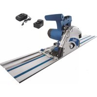
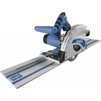
8.11 Using the laser (Fig. 16,17)
- To switch on: Move the ON/OFF switch of the la- ser (35) to the “1” position. A laser line is projected onto the material you wish to process, providing an exact guide for the cut.
- To switch o: Move the ON/OFF switch of the la- ser (35) to the “0” position.
- Replacing the battery: Switch o the laser (34). Remove the battery compartment cover (37). Re- move the batteries and replace with new batteries (3 x LR44) Check that the battery terminals are positioned correctly when inserting new batteries. Close the battery compartment (36) again.
8.12 Changing the speed (Fig. 2)
The saw has 2 speed ranges: langsam schnell vitesse lente vitesse rapide slow fast Pomalu rychle Pomalý rýchly Počasnega hitrega lassú gyors бавно бързо Nopea hidas
- To operate the saw at a speed of 3200 rpm (metal), set the switch (42) to position I.
- To operate the saw at a speed of 4500 rpm (wood), set the switch (42) to position II.
9. Transport (Fig. 1,2)
- Tighten the set screw (26) in order to lock the ro- tary table (16)
- Activate the release lever (3), press the machine head (5) downwards and secure with the safety pin (24). The saw is now locked in its bottom position.
- Fix the saw’s drag function with the locking screw for drag guide (23) in rear position.
- Carry the equipment by the xed saw table (17).
- When reassembling the equipment proceed as de- scribed under section 7.1.
m Warning! Prior to any adjustment, maintenance or service work disconnect the mains power plug! General maintenance measures Wipe chips and dust o the machine from time to time using a cloth. In order to extend the service life of the tool, oil the rotary parts once monthly. Do not oil the motor. When cleaning the plastic do not use corrosive prod- ucts. Brush inspection Check the carbon brushes after the rst 50 operat- ing hours with a new machine, or when new brushes have been tted. After carrying out the rst check, repeat the check every 10 operating hours. If the carbon is worn to a length of 6 mm, or if the spring or contact wire are burned or damaged, it is necessary to replace both brushes. If the brushes are found to be usable following removal, it is pos- sible to reinstall them. Service information Please note that the following parts of this product are subject to normal or natural wear and that the follow- ing parts are therefore also required for use as con- sumables. Wear parts*: Carbon brush, saw blade, battery, table liners, sawdust bag, V-belts
- Not necessarily included in the scope of delivery!30 GB
13. Disposal and recycling
The equipment is supplied in packaging to prevent it from being damaged in transit. The raw materials in this packaging can be reused or recycled. The equip- ment and its accessories are made of various types of material, such as metal and plastic. Defective components must be disposed of as special waste. Ask your dealer or your local council. Old devices must not be disposed of with house- hold waste! This symbol indicates that this product must not be disposed of together with domestic waste in compliance with the Directive (2012/19/EU) pertaining to waste electrical and electronic equipment (WEEE). This product must be disposed of at a designated collection point. This can occur, for example, by handing it in at an author- ised collecting point for the recycling of waste elec- trical and electronic equipment. Improper handling of waste equipment may have negative consequenc- es for the environment and human health due to po- tentially hazardous substances that are often con- tained in electrical and electronic equipment. By properly disposing of this product, you are also con- tributing to the eective use of natural resources. You can obtain information on collection points for waste equipment from your municipal administration, public waste disposal authority, an authorised body for the disposal of waste electrical and electronic equipment or your waste disposal company. Batteries and rechargeable batteries do not be- long in the household waste! As the consumer you are required by law to bring all batteries and rechargeable batteries, regardless whether they contain harmful sub- stances* or not, to a collection point run by the local authority or to a retailer, so that they can be disposed of in an environmentally friendly manner. *labelled with: Cd = cadmium, Hg = mercury, Pb = lead
- Remove the batteries from the laser before dispos- ing of the machine and the batteries.
Store the device and its accessories in a dark, dry and frost-proof place that is inaccessible to children. The optimum storage temperature is between 5 and 30˚C. Store the electrical tool in its original packaging. Cover the electrical tool in order to protect it from dust and moisture. Store the operating manual with the electrical tool.
12. Electrical connection
The electrical motor installed is connected and ready for operation. The connection complies with the applicable VDE and DIN provisions. The customer‘s mains connection as well as the extension cable used must also comply with these regulations. Damaged electrical connection cable The insulation on electrical connection cables is of- ten damaged. This may have the following causes:
- Passage points, where connection cables are passed through windows or doors.
- Kinks where the connection cable has been im- properly fastened or routed.
- Places where the connection cables have been cut due to being driven over.
- Insulation damage due to being ripped out of the wall outlet.
- Cracks due to the insulation ageing. Such damaged electrical connection cables must not be used and are life-threatening due to the insula- tion damage. Check the electrical connection cables for damage regularly. Make sure that the connection cable does not hang on the power network during the inspection. Electrical connection cables must comply with the applicable VDE and DIN provisions. Only use con- nection cables with the marking „H05VV-F“. The printing of the type designation on the connec- tion cable is mandatory. AC motor
- The mains voltage must be 230 V~
- Extension cables up to 25 m long must have a cross-section of 1.5 mm2. Connections and repairs of electrical equipment may only be carried out by an electrician. Please provide the following information in the event of any enquiries: Type of current for the motor
Fault Possible cause Remedy Motor does not work Motor, cable or plug defective, fuses burnt Arrange for inspection of the machine by a spe- cialist. Never repair the motor yourself. Danger! Check fuses and replace as necessary The motor starts up slowly and does not reach operating speed. Voltage too low, coils damaged, capacitor burnt Contact the utility provider to check the voltage. Arrange for inspection of the motor by a special- ist. Arrange for replacement of the capacitor by a specialist Motor makes exces- sive noise Coils damaged, motor defective Arrange for inspection of the motor by a special- ist The motor does not reach its full power. Circuits in the network are overloaded (lamps, other motors, etc.) Do not use any other equipment or motors on the same circuit Motor overheats eas- ily. Overloading of the motor, insucient cool- ing of the motor Avoid overloading the motor while cutting, remove dust from the motor in order to ensure optimal cooling of the motor Reduced cutting power when sawing Saw blade too small (ground too much) Readjust end stop of the saw unit Saw cut is rough or wavy Saw blade dull, tooth shape not appropriate for the material thickness Resharpen saw blade and/or use suitable saw blade Workpiece pulls away and/or splinters Excessive cutting pressure and/or saw blade not suitable for use Insert suitable saw blade32 FR Table des matières: Page: