T0053420699N - Welding machine Weller - Free user manual and instructions
Find the device manual for free T0053420699N Weller in PDF.
Frequently Asked Questions - T0053420699N Weller
Download the instructions for your Welding machine in PDF format for free! Find your manual T0053420699N - Weller and take your electronic device back in hand. On this page are published all the documents necessary for the use of your device. T0053420699N by Weller.
USER MANUAL T0053420699N Weller
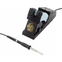
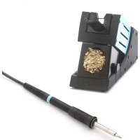
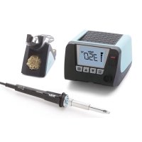
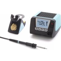
WX 1, WX 2, WXD 2, WXA 2
English Technical Data | Safety information | Menu navigation | Care and maintenance | Warranty
WX 1 WX 2 WXD 2 WXA 2
Thank you for the condence you have shown in buying this device. The device has been manufactured in accordance with the most rigorous quality standards which ensu- re that it operates perfectly. Read these instructions and the accompanying safety information carefully before starting up the device and starting work with the device. Keep these instructions in a place that is acces- sible to all users. These instructions contain important information which will help you to start up, operate and service the device safely and correctly as well as to eliminate simple faults and malfunctions yourselves. The device has been manufactured in accordance with state-of-the-art technology and acknow- ledged regulations concerning safety. There is nevertheless the risk of personal injury and damage to property if you fail to observe the safety information set out in the accompanying booklet and the warnings given in these instructions. Safety information For safety reasons, children and youths under the age of 16, as well as persons who are not familiar with these operating inst- ructions, may not use the device. Children should be supervised in order to ensure that they do not play with the tool. This device is not intended for use by persons (including children) with limited physical, sensory or mental aptitude, or by persons who lack knowledge or experience in handling the device. Warning! Electrical shock Connecting the control unit incorrectly poses a risk of injury due to electric shock and can damage the device. Carefully read the attached safety information, the safety information accompanying these operating instructions as well as the operating instructions for your control unit before putting the control unit into operation and observe the safety precautions specied therein. Only connect WELLER WX tools. Never use the USB port as a power supply for third-party devices. If the device is faulty, active electrical conductors may be bare or the PE conductor may not be functional. Repairs must always be referred to a Weller-trained specialist. If the electrical tool‘s power supply cord is damaged, this must be replaced with a specially prefabricated power supply cord available through the customer service organisation. Warning! Risk of burns Risk of burns from the soldering tool while the control unit is operating. Tools may still be hot long after they have been switched off. Always place the soldering tool in the safety rest while not in use. Only connect the vacuum and hot air at the designated points. Do not direct hot air soldering tools at people or inammable objects. For your safety31
For your safety Specied Conditions Of Use Supply unit for WELLER WX soldering tools. Use the soldering station / desoldering station / hot air station exclusively for the purpose indicated in the operating instructions of soldering and desoldering under the conditions specied herein. Flammable gases and liquids may not be extracted. The device may only be used with correctly tted and suitable lter cartridges. Replace lter cartridges when full. Only use the device indoors. Protect against mois- ture and direct sunlight. Intended use of the soldering station/ desoldering station also includes the requirement that you adhere to these instructions, observe all other accompanying documents, comply with national accident prevention guidelines applicable at the place of use. The manufacturer will not be liable for unautho- rised modications to the device. User groups Due to differing degrees of risk and potential hazards, several work steps may only be performed by trained experts. Work step User groups Default soldering parameters Specialist personnel with technical training Replacing electrical replacement parts Electricians Default maintenance intervals Safety expert Operation Filter change Non-specialists Operation Filter change Replacing electrical replacement parts Technical trainees under the guidance and supervision of a trained expert Starting up the device Caution! Please adhere to the operating instructions of the connected devices. Put the tool into operation as described in the chapter „Placing into operation“. Check to see if the mains voltage mat- ches the ratings on the nameplate. Make sure the machine is switched off before plugging in. After switching on the device, the microprocessor carries out a self- test and reads out the values of the parameters stored in the tool. The set-point temperature and xed temperatures are stored in the tool. The actual temperature value increases to the set-point temperature (= soldering tool is heated up). WXA 2: Nitrogen N2 reduces oxidation and ux remains active for longer. We recommend the nitrogen N2 that is available in steel bottles. The bottle must be equipped with a 0-10 bar pressure reducer.32
Soldering and desoldering Carry out soldering work as directed in the opera- ting instructions of your connected soldering tool. Handling the soldering tips Coat the selective and tinnable soldering tip with solder when heating it up for the rst time. This removes oxide coatings which have formed during storage and impurities from the soldering tip. Make sure that the soldering tip is well coated with solder during breaks between soldering work and prior to storage of the device. Do not use aggressive uxing agents. Always make sure that the soldering tips are tted properly. Select as low a working temperature as possible. Select the largest possible soldering tip shape for the application. Rule of thumb: the soldering tip should be roughly as large as the soldering pad. Coat the soldering tip well with solder to ensure that there is efcient heat transfer between the soldering tip and the soldering area. Prior to extended breaks between soldering work, switch off the soldering system or use the Weller function to reduce the temperature when the soldering equipment is not in use. Coat the tip with solder prior to storage if you do not intend to use the soldering iron for an extended period of time. Apply solder directly to the soldering area, not to the soldering tip. Change the soldering tips using the designated tool. Do not apply mechanical force to the soldering tip. Notice The control units have been adapted to hold a medium-sized soldering tip. Discrepancies may occur if the tip is changed or a different shaped tip is used. WX 2, WXD 2, WXA 2: Overload cut-out (255 W) To avoid overloading a WX station, one channel is automatically deactivated if the power output of both tool channels is greater than 255 watt (Auto-Off). An overload cut-out will also occur if the following combinations of tools are connected: e. g. - 2 WXHP 120 heating plates - A WXHP 120 heating plate and desoldering iron WXDP 120 or WXDV 120 Equipotential bonding
Four variants are possible by connecting the 3.5 mm jack socket differently: a Hard-grounded supplied without plug. b Equipotential bonding with plug, equaliser at centre contact. c Floating with plug d Soft-grounded with plug and soldered resistor. Ground- ed through selected resistor. For your safety33
For your safety Carrying out a rmware update Notice The station must not be switched off while the rmware update is running. Switch off station 1.
2. Insert the memory stick into the USB port.
Switch on station 3. The rmware update is performed automatically. If you have a more already installed more recent rmware on your station, this will not be changed. Care and maintenance Warning! Before doing any work on the machi- ne, pull the plug out of the socket. Clean the operator panel, if dirty, using a suitable cleaning cloth. Seal ports which are not in use with covering caps. Warning! Risk of burns Only replace solder tips when cold Replace and clean suction nozzles only when hot and using the suitable tool Only replace hot air nozzles using the suitable tool Only clean or replace solder collection tubes when cold Filter change Regularly check the main lter for vacuum, and replace it if necessary. Warning! Working without a lter can result in irreparable damage to the vacuum unit. Check before starting soldering whether a main lter is inserted. Contaminated lters must be treated as special waste. Dispose of replaced equipment parts, lters or old devices in accordance with the rules and regulations applicable in your country. Wear suitable protective gear. Warning! Use original replacement parts only. Warranty Claims by the buyer for physical defects are time- barred after a period of one year from delivery to the buyer. This does not apply to claims by the buyer for indemnication in accordance with §§ 478, 479 BGB (German Federal Law Gazette). We shall only be liable for claims arising from a warranty furnished by us if the quality or durability warranty has been furnished by use in writing and using the term „Warranty“. The warranty shall be void if damage is due to impro- per use and if the device has been tampered with by unauthorised persons. Subject to technical alterations and amendments. For more information please visit www.weller-tools. com.34
Standby Temp. Menu access Tool parameters Note The soldering tools have a usage detector (sensor) in the handle which automatically starts the cooling cycle when the soldering tool is not in use. The standby temperature is automatically set after a temperature deactivation. Standby time (temperature deactivation) Menu access Tool parameters When the soldering tool is not in use, the tem- perature is reduced to Standby temperature on expiration of the set Standby time. The display reads „Standby“. Press control key to exit Standby mode. The sensor integrated tool detects the change in state and deactivates Standby mode as soon as the tool is moved. Option Description OFF standby time is deactivated (factory setting) 1-999 min standby time, individually adjustable --- The tool is not supported AUTO OFF time (automatic switch-off time) Menu access Tool parameters When the soldering tool is not in use, the soldering tool heater is switched off when the AUTO OFF time expires. Temperature deactivation is performed indepen- dently of the set standby function. The actual temperature is indicated by ashing LED and serves as a residual heat display. The display reads „OFF“. Option Description OFF AUTO OFF function is deactivated (factory setting) 1-999 min AUTO-OFF time, can be set indivi- dually. Sensitivity Menu access Tool parameters Option Description Low Non-Sensitive – Reacts to heavy (long) movement Normal Standard (factory setting) High Sensitive - Reacts to light (short) movement --- The tool is not supported Max. hot air duration WXHAP 200 Open Menu Tool parameters The on-time of the hot air ow of the WXHAP 200 can be limited in increments of 1 to between 0 and 300 sec. The factory default is 0 s („OFF“), i.e. air ows only as long as the button on the hot air tool or the optional footswitch is pressed. Option Description OFF No duration dened (factory setting) 1-300 s Individually adjustable Parameter menu35
Parameter menu Offset (Temperature-Offset) Open Menu Tool parameters The actual soldering-tip temperature can be adapted by entering a temperature offset around ± 40 °C (± 72 °F). Perform. Mode Open Menu Tool parameters The function determines the heating characteris- tics of the soldering tool to achieve the set tool temperature. Option Description Standard Adapted (medium) heating (factory setting) Min. Slow heating Max. rapid heating Button lock WXHAP 200 Open Menu Tool parameters This function can be used to adjust the factory button presets of the WXAHP tool. Option Description OFF – ON The WXHAP 200 is switched on the rst time the button is pressed and switched off the next time the button is pressed. Process window Open Menu Tool parameters The temperature range set in the process window determines the signal response of the oating switching output. Notice On tools with an LED ring light (e.g. WXDP 120), the process window denes the illumination characteristics of the LED ring light. If the LED is continuously illuminated, this means that the preselected temperature has been reached or that the temperature is within the predetermined process window. A ashing LED indicates that the system is heated or that the temperature is outside the process window. Language Open Menu Station parameters CHN
Parameter menu Password (lock function) Open Menu Station parameters After switching the lock function on, only the xed temperature keys can be operated on the solde- ring station. All other settings are disabled until the repair station is unlocked again. Notice If you want only one temperature value to be selectable, the control keys xed temperature keys) must be set to the same temperature value. Lock the soldering station: Set the required three-character locking code (bet- ween 001-999) with the turn-and-click wheel. The lock is active (the display shows a lock symbol). Unlocking the soldering station
1. Call up the parameter menu. If the lock function
is active, the password menu item opens automatically. Three stars (***) are shown on the display.
2. Set the three-character locking code using the
turn-and-click wheel.
3. Conrm the code with the Enter key.
Forgotten code? Please contact our Customer Service: technical-service@ weller-tools.com Vacuum pre-feed WXD 2 only Open Menu Station parameters In order to prevent the pump from starting pre- maturely or to ensure a dened soldering-joint preheating time, it is possible to set an ON delay. Option Description 0 sec OFF: vacuum pre-feed function is OFF (factory setting) 1-10 sec ON: vacuum pre-feed time, individually Vacuum run-on (WXD 2 only) Open Menu Station parameters To prevent the desoldering iron from becoming clogged, it is possible to set a vacuum run-on time. Option Description 0 sec OFF: vacuum run-on function is OFF (factory setting) 1-10 sec ON: vacuum run-on time, individually adjustable Touchtones on/off Open Menu Station parameters Option Description ON On OFF Off37
Parameter menu Robot output Open Menu Station parameters The robot output is on the back of the device. WX 1: OFF - ON - ZeroSmog - Stop&Go WX 2 / WXD 2: OFF- Left - Right - Left & Right - ZeroSmog - Stop&Go Option Description Left Left tool channel (factory setting) Right Right tool channel Left & Right Both tool channels ZeroSmog The rear oating switching output is closed when a tool is in use. Selected Zero Smog extraction systems can be connected using an optional adaptor (WX HUB). The rear RS 232 port continues to be functional. Switching output is open in the Standby, AUTO-OFF or OFF positions, or if no tool is inserted. Stop&Go The rear RS232 port is used to drive an optotransmitter so that a KHE/KHP can be activated via an optical bre. The output is activated when a tool is used. In addition, the oating switched output is closed. The output is OFF in the Standby, AUTO-OFF or OFF positions, or if no tool is inserted. Notice If the robot is at working temperature, the display will show – ok –. Not available with Zero Smog + Stop&Go Footswitch (WXD 2 only + WXA 2) Open Menu Station parameters In order to prevent the pump from starting pre- maturely or to ensure a dened soldering-joint preheating time, it is possible to set an ON delay. Option Description OFF Footswitch is off ON Footswitch is on The front RS232 port is congured as a foot switch input for activating the air ow. Connecting auxiliary devices Please observe the overview diagrams. Auxiliary devices can be connected either to the port on the front panel and/or to the port on the back of the Soldering Station. The Soldering Station detects automatically which auxiliary device is connected. The Soldering Sta- tion shows the symbol or name of the connected auxiliary device on the front port or rear port. Setting the parameters of auxiliary devices
1. Select the auxiliary device using the auxiliary
device key (front/back). The variable parameters (e.g. speed) are dis- played.
3. Conrm the value with the Enter key38
Technical Data soldering station soldering station desoldering station Hot air station
WX 1 WX 2 WXD 2 WXA 2
(58-87 psi); oil-free, dry compressed air Inlet pressure
Error messages and error clearance Message/symptom Possible cause Remedial measures Display: „- - - Tool has not been detected Tool defective Check connection of tool to device Check connected tool No display function display OFF No mains supply voltage Turn on mains power switch Check mains supply voltage Check device fuse OFF Channel cannot be switched on Overload cut-out Channel switched off Only one soldering iron can be operated. WXD 2: No vacuum at desoldering tool Vacuum not connected Desoldering nozzle clogged Compressed air not or incorrectly connected Connect vacuum hose to vacuum connection Service desoldering nozzle using cleaning tool Connect compressed air to compressed air connection or check WXD 2: Insufcient vacuum at desolde- ring tool Filter cartridge on desoldering tool full Main lter on soldering station full Change lter cartridge on desoldering tool full Change the main lter element on the soldering station WXA 2: Hot air tool has no air Air hose not connected Compressed air not or incorrectly connected Connect compressed air to compressed air hose or check Connect air hose of tool to WXA 2 or check rear port Does not function with Zero Smog/ WHP/PC/ WFV 60A Robot output set to Stop/Go Deactivate Stop & Go function; Or use front RS 232 port front port Does not function with Zero Smog/ WHP/PC/ WFV 60A Footswitch is on Deactivate Footswitch; Or use rear RS 232 port40
Symbols Caution! Read the operating instructions! Before performing work of any kind on the unit, always disconnect the power plug from the socket. ESD-compatible design and ESD- compatible workstation Equipotential bonding CE mark of conformity Fuse Safety transformer Soldering Desoldering Hot air Disposal Do not dispose of electric tools together with household waste material! In observance of European Directive 2012/19/EU on waste electrical and electronic equipment and its implemen- tation in accordance with national law, electric tools that have reached the end of their life must be collected separately and returned to an environmentally compatible recycling facility. Dispose of replaced equipment parts, lters or old devices in accordance with the rules and regulations applicable in your country. Original declaration of conformity soldering station WX1, WX2 desoldering station WXD 2 Hot air station WXA 2 Tool WXP 65, WXP 120, WXP 200, WXMP, WXMT We hereby declare that the products described herein comply with the following guidelines: 2004/108/EG, 2006/95/EG, 2011/65/EU (RoHS) Applied harmonised standards: DIN EN 55014-1: 2012-05 DIN EN 60335-1: 2012-10 DIN EN 55014-2: 2009-06 DIN EN 60335-2-45: 2012-08 DIN EN 61000-3-2: 2010-03 / 2011-06 DIN EN 62233: 2008-11 / 2009-04 DIN EN 61000-3-3: 2012-07 DIN EN 50581:2013-02 Besigheim, 2014-07-30 T. Fischer S. Hofmann Technical director Managing director Authorised to compile technical documentation. Weller Tools GmbH Carl-Benz-Straße 2, 74354 Besigheim, Germany41