
GIM 60L - Electronic spirit level BOSCH - Free user manual and instructions
Find the device manual for free GIM 60L BOSCH in PDF.
| Product type | Electronic bubble level |
| Brand | Bosch |
| Model | GIM 60L |
| Dimensions (L x W x H) | 600 x 27 x 59 mm |
| Weight (according to EPTA 01/2003) | 0.9 kg |
| Power supply – tilt measurement | 1 x 9V battery 6LR61 |
| Power supply – laser | 2 x 1.5V LR03 (AAA) batteries |
| Battery life – measurement | approx. 300 h |
| Battery life – laser | approx. 20 h |
| Measuring range | 0–360° (4 x 90°) |
| Accuracy at 0°/90° | ±0.05° |
| Accuracy from 1° to 89° | ±0.2° |
| Laser class | 2 (635 nm, <1 mW) |
| Laser range | 30 m |
| Tripod thread | 1/4" |
| Operating temperature | −10 °C to +50 °C |
| Storage temperature | −20 °C to +70 °C |
| Measurement units | °, %, mm/m |
| Main functions | Tilt measurement, aiming laser, hold/copy, zero point adjustment, calibration (CAL), acoustic signal, 180° display rotation |
| Mounting | Integrated magnets (14), fastening straps (25) |
| Care and cleaning | Soft damp cloth; do not immerse; store in the supplied protective case |
| Laser safety | Do not look into the beam, do not point at people or animals |
| After-sales service France | 0811 36 01 22 (cost of a local call); contact.outillage-electroportatif@fr.bosch.com |
| Supplied accessories | Protective case, fastening strap, batteries (not specified) |
| Article number | 3601 K76 300 |
Frequently Asked Questions - GIM 60L BOSCH
User questions about GIM 60L BOSCH
0 question about this device. Answer the ones you know or ask your own.
Ask a new question about this device
Download the instructions for your Electronic spirit level in PDF format for free! Find your manual GIM 60L - BOSCH and take your electronic device back in hand. On this page are published all the documents necessary for the use of your device. GIM 60L by BOSCH.
USER MANUAL GIM 60L BOSCH
Power Tools Division
70745 Leinfelden-Echterdingen
Germany
www.bosch-pt.com
1618C0062X(2012.08)T/223XXX

GIM 60 L Professional

BOSCH
bgOpnHnHaHa HnHCTpyKuHa
OBJ BUCH-1628-002.book Page 13 Monday, August 27, 2012 12:22 PM
English|13
Working safely with the measuring tool is possible only when the operating and safety information are read completely and the instructions contained therein are strictly followed. Never make warning labels on the measuring tool unrecognisable. SAVE THESE INSTRUCTIONS.
- Caution - The use of other operating or adjusting equipment or the application of other processing methods than those mentioned here, can lead to dangerous radiation exposure.


OBJ BUCH-1628-002.book Page 14 Monday, August 27, 2012 12:22 PM

14 | English
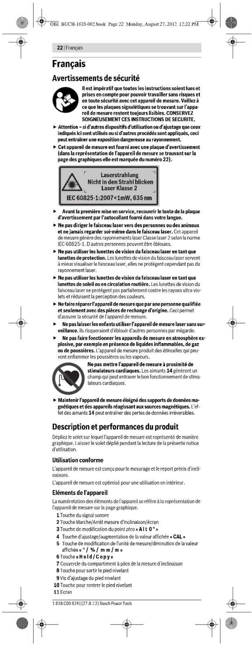
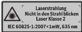
The measuring tool is provided with a warning label (marked with number 22 in the representation of the measuring tool on the graphics page).

If the text of the warning label is not in your national language, stick the provided warning label in your national language over it before operating for the first time.
Do not direct the laser beam at persons or animals and do not stare into the laser beam yourself. This measuring tool produces laser class 2 laser radiation according to IEC 60825-1. This can lead to persons being blinded.
Do not use the laser viewing glasses as safety goggles. The laser, but they do not protect against laser radiation.
Do not use the laser viewing glasses as sun glasses or in traffic. The laser viewing glasses do not afford complete UV protection and reduce colour perception.
- Have the measuring tool repaired only through qualified specialists using original spare parts. This ensures that the safety of the measuring tool is maintained.
Do not allow children to use the laser measuring tool without supervision. They could unintentionally blind other persons or themselves.
Do not operate the measuring tool in explosive environments, such as in the presence of flammable liquids, gases or dusts. Sparks can be created in the measuring tool which may ignite the dust or fumes.

Keep the measuring tool away from cardiac pacemakers. The magnets 14 generate a field that can impair the function of cardiac pacemakers.
- Keep the measuring tool away from magnetic data medium and magnetically-sensitive equipment. The effect of the magnets 14 can lead to irreversible data loss.
Product Description and Specifications
Please unfold the fold-out page with the representation of the measuring tool and leave it unfolded while reading the operating instructions.
Intended Use
The measuring tool is intended for precise measuring and transferring of grades.
The measuring tool is optimized for indoor use.
Product Features
The numbering of the product features shown refers to the illustration of the measuring tool on the graphic page.
1 Audio signal button
2 On/Off button for grade measurement/display
3 "A1t0" button for changing the zero point
4 "CAL" button for calibration/increasing the display value
5 " / %/ mm/m" button for changing the unit of measure/reducing the display value
6 " Hold / Copy" button
7 Battery lid, grade measurement
8 Button for extracting the levelling foot
9 Adjusting screw of the levelling foot
3.0 Switch for retracting the levelling foot
1 Display
2.2 Spirit level, horizontal
3.3 Spirit level, vertical
4 Magnets
4.5 Opening for strap attachment
6 Pedestal
7.7 Levelling foot
8 Tripod mount 1/4"
.9 Laser On/Off button
20 Battery lid, laser
21 Exit opening for laser beam
2 Laser warning
23 Serial number
24 Protective pouch
25 Fastening strap
26 Tripod
* The accessories illustrated or described are not included as standard delivery.
1681C0062X|(27.8.12)BoschPowerTools


English | 15
Display Elements
a Alignment aides
bReading
c Audio signal indicator
Battery low indicator
e Indicator for changed zero point
fUnit of measure
Technical Data
| Digital level GIM 60 L | |
| Article number | 3601 K76 300 |
| Measuring range | 0-360° (4x90°) |
| Measuring accuracy | |
| -0° / 90° | ± 0.05° |
| -1° - 89° | ± 0.2° |
| Working range of laser1) | 30 m |
| Levelling accuracy of laser | ± 0.5 mm/m |
| Clearance of laser exit - bottom edge of measuring tool | 24 mm |
| Laser class | 2 |
| Laser type | 635 nm, <1 mW |
| Laser beam diameter (at 25 °C) approx. | |
| -at 5 m distance | 3.5 mm |
| -at 10 m distance | 6 mm |
| Operating temperature | -10 °C...+50 °C |
| Storage temperature | -20 °C...+70 °C |
| Relative air humidity, max. | 90 % |
| Tripod mount | 1/4" |
| Batteries | |
| -Grade measurement | 1x9V6LR61 |
| -Laser operation | 2x1.5VLR03 (AAA) |
| Operating life time, approx. | |
| -Grade measurement | 300 h |
| -Laser operation | 20 h |
| Weight according to EPTA-Procedure 01/2003 | 0.9 kg |
| Dimensions (length x width x height) | 600 x 27 x 59 mm |
| 1) The working range can be decreased by unfavourable environmental conditions (e.g. direct sun irradiation). | |
| The measuring tool can be clearly identified with the serial number 23 on the type plate. | |
Assembly
Inserting/Replacing the Battery
The measuring tool has two separate electric circuits: The grade measurement and display are powered by a different battery than the laser.
Alkali-manganese batteries are recommended for the measuring tool.
- Remove the batteries from the measuring tool when not using it for extended periods. When storing for extended periods, the batteries can corrode and discharge themselves.
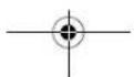
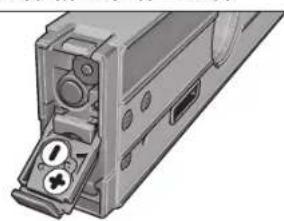
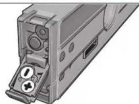
Inserting/Replacing the Battery for Grade Measurement
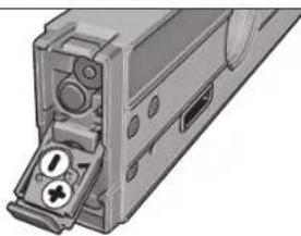
Carefully remove the battery lid 7 with the battery holder from the measuring tool. Pay attention that neither the connection cables of the battery nor the battery lid become damaged. Damage on the supporting surfaces of the battery compartment 7 can lead to faulty measurements.
Connect the battery to the battery tray observing the correct polarity. Insert the battery lid with the battery tray into the measuring tool in such a manner that the connection cables are not pinched.
When switching on the grade measurement for the first time after changing the battery, all display elements light up for 1 s and an audio signal sounds. All saved settings (measuring mode, set unit of measure) are deleted when changing the battery.
When the battery low indicator d lights up, the battery must be replaced.
Inserting/Replacing the Batteries for the Laser
Fold out the battery lid 20 and insert the batteries. When inserting, pay attention to the correct polarity according to the representation on the inside of the battery lid.
When the laser no longer lights up, the batteries must be replaced.
Bosch Power Tools 1618 C00 62X| (27.8.12)


English | 17
Switching the Laser On and Off
To switch on the laser, press the On/Off button 19 to position "I".
Do not point the laser beam at persons or animals and do not look into the laser beam yourself, not even from a large distance.
To switch off the laser, press the On/Off button 19 to position "0".
Do not leave the measuring tool unsupervised with the laser switched on, and switch the laser off after use. Other persons could be blinded by the laser beam.
When not using the laser, switch it off in order to save energy.
Changing the Unit of Measure (see figure A)
You can change between the units of measure 一 ^ 一 95^ and "mm/m" at any time. For this, press the button for changing the unit of measure 5 as often as required until the desired setting is displayed in indicator f. The current measuring value is automatically converted.
The unit of measure setting is retained when switching the measuring tool on or off.
Switching the Audio Signal On/Off
The audio signal can be switched on/off with the audio signal button 1. When the audio signal is switched on, indicator c appears in the display.
The signal tone setting is maintained after switching the measuring tool off and on again.
Measured-value Indication and Alignment Aides
For each movement of the measuring tool, the measured value is updated. After moving the measuring tool to any extent, wait until the measured value no longer changes before reading the value.
Depending on the position of the measuring tool, the measured value and the unit of measure are indicated in the display rotated by 180^ . Thus, the indication can also be read for overhead work.
By means of the alignment aides a in the display the measuring tool indicates the direction in which it has to be inclined, in order to reach the target value. For standard measurements, the target value is the horizontal or the vertical line; in "Copy" mode, the target value is the saved measuring value and when changing the zero point, the target value is the saved zero point.
When the target value is reached, the arrows of the alignment aides a go out and a continuous audio signal sounds when the audio signal is switched on.
Measuring Functions
Holding/Copying a Measured Value (see figure D)
Two functions can be controlled with the "Hold/Copy" button 6:
-
Holding ("Hold") of a measured value, even when the measuring tool is moved afterwards (e.g., because the measuring tool is in a position, in which the display cannot be read);
-
Copying ("Copy") of a measured value.
"Hold" function:
- Press the "Hold/Copy" button 6. The current measured value b is held in the display; all display elements flash, with exception of the measured value.
To switch to the "Copy" function, press the audio signal button 1; to start a new measurement, press the "Hold/Copy" button 6.
"Copy" function:
- Switch the audio signal on (see "Switching the Audio Signal On/Off", page 17).
Press the "Hold/Copy" button 6. The current measuring value is saved. A short beep sounds, the indicators for unit of measure f and audio signal c flash.
Coarsely measured values can be corrected before transferring them. To increase the saved value, press the button for increasing the display value 4; to decrease the value, press the button for decreasing the display value 5.
- Position the measuring tool at the target location, where the measured value is to be transferred. As shown in the figure, the alignment of the measuring tool is irrelevant. The alignment aids a indicate the direction in which the measuring tool has to be moved. In order to reach the angle to be copied. When reaching the saved value, an audio signal sounds and the alignment aids a go out.
Press the "Hold/Copy" button 6 again to start a new measurement.
Changing the Zero Point
For easier checking of grades (e.g. 45^ ), the zero point of a measurement can be changed.
Align the measuring tool by placing it against a reference workpiece in such a manner that the desired new zero point is displayed as the measuring value (e.g., 45.1"). Press the "Alt0" button 3. The measured value b and the indicator for a changed zero point e flash.
Coarsely measured values can be corrected as long as the measured value b flashes: To increase the saved value, press the button for increasing the display value 4; to decrease the value, press the button for decreasing the display value 5 (e.g. from 45.1^ to 45.0^ ). 3 s after the last button actuation, the displayed grade value is saved as the new reference value.


18 | English
After the value has been saved, the flashing indicator e indicates the changed zero point. The current measuring value, with reference to the new zero point, is displayed in measuring indicator b; the alignment aides and the audio signals also refer to the new zero point. Example: For a 43.8^ grade with reference to the horizontal line and a saved zero point of 45^ , the value 1.2^ is displayed as the measuring value.
To return to the standard zero point 0^ , press either of buttons "Alt 0" 3, "Hold/Copy" 6 or "CAL" 4. The indicator for changed zero point e goes out.
Contact-free Measuring/Transferring of Grades
With the laser, it is possible to measure and transfer grades contact-free, even over greater distances.
Do not point the laser beam at persons or animals and do not look into the laser beam yourself, not even from a large distance.
Always use the centre of the laser point for marking. The size of the laser point changes with the distance.
To measure grades, align the measuring tool in such a manner that the laser beam runs alongside the surface to be measured. To transfer grades, align the measuring tool in such a manner that the desired grade is displayed as measuring value b, and mark the grade on the target surface using the laser point.
Note: When transferring grades via laser, take into consideration that the laser comes out 24 mm above the bottom edge of the measuring tool.
Accuracy Check and Calibration of the Measuring Tool
Checking the Measuring Accuracy
Check the accuracy of the measuring tool prior to critical measurements, after intense variations in temperature as well as after heavy impact.
Before measuring angles < 45^ , the accuracy check should take place on a level and roughly horizontal surface; before measuring angles >45^ , on a level and roughly vertical surface.
Switch the measuring tool on and place it on the horizontal or vertical surface.
Select the unit of measure (see "Changing the Unit of Measure", page 17).
Wait for 10 s and note down the measured value.
Rotate the measuring tool by 180^ around its vertical axis. Wait again for 10 s and note down the second measured value.
Calibrate the measuring tool only when the difference between both reading values is greater than 0.1^
Calibrate the measuring tool in the position (vertical or horizontal), in which the difference of the measured values has been determined.
Calibration for Horizontal Surfaces (see figure E)
The surface onto which you place the measuring tool must not deviate from the horizontal line by more than 5^ . If the deviation is greater, the calibration process is discontinued with the indication "---".
① Switch the measuring tool on and position it on the horizontal surface in such a manner that the spirit level 12 faces upward and the display 11 faces you. Wait for 10 s.
Then press the calibration button "CAL"4 for approx. 2 s until "CAL1" briefly appears in the display. Afterwards, the measuring value flashes in the display.
Turn the measuring tool by 180^ around the vertical axis so that the spirit level still faces upward, but the display 11 faces away from you. Wait for 10 s.
Then press the calibration button "CAL" 4 again. "CAL2" is briefly indicated in the display. Afterwards, the measuring value appears in the display (no longer flashing). The measuring tool is now re-calibrated for this supporting surface.
Alter this, the measuring tool must be calibrated for the opposite supporting surface. Rotate the measuring tool around the horizontal axis in such a manner that the spirit level 12 faces downward and the display 11 faces you. Place the measuring tool on the horizontal surface. Wait for 10 s.
Then press the calibration button "CAL"4 for approx. 2 s until "CAL1" briefly appears in the display. Afterwards, the measuring value flashes in the display.
Turn the measuring tool 180^ around the vertical axis so that the spirit level still faces downward but the display 11 is facing away from you. Wait for 10 s.
Then press the calibration button "CAL" 4 again. "CAL2" is briefly indicated in the display. Afterwards, the measuring value appears in the display (no longer flashing). The measuring tool is now re-calibrated for both horizontal supporting surfaces.
Note: If the measuring tool is not turned around the axis shown in the figure in steps ② and ⑦, then the calibration cannot be completed ("CAL2" is not indicated in the display).
English|19
Calibration for Vertical Surfaces (see figure F)
The surface onto which you place the measuring tool must not deviate from the vertical line by more than 5^ . If the deviation is greater, the calibration process is discontinued with the indication "---".
Switch the measuring tool on and position it on the vertical surface in such a manner that the spirit level 13 faces upward and the display 11 faces you. Wait for 10 s.
Then press the calibration button "CAL"4 for approx. 2 s until "CAL1" briefly appears in the display. Afterwards, the measuring value flashes in the display.
Turn the measuring tool by 180^ around the vertical axis so that the spirit level still faces upward, but the display 11 faces away from you. Wait for 10 s.
Then press the calibration button "CAL" 4 again. "CAL2" is briefly indicated in the display. Afterwards, the measuring value appears in the display (no longer flashing). The measuring tool is now re-calibrated for this supporting surface.
Alter this, the measuring tool must be calibrated for the opposite supporting surface. Rotate the measuring tool around the horizontal axis in such a manner that the spirit level 13 faces downward and the display 11 faces you. Place the measuring tool against the vertical surface. Wait for 10 s.
Then press the calibration button "CAL"4 for approx. 2 s until "CAL1" briefly appears in the display. Afterwards, the measuring value flashes in the display.
Turn the measuring tool 180^ around the vertical axis so that the spirit level still faces downward but the display 11 is facing away from you. Wait for 10 s.
Then press the calibration button "CAL" 4 again. "CAL2" is briefly indicated in the display. Afterwards, the measuring value appears in the display (no longer flashing). The measuring tool is now re-calibrated for both vertical supporting surfaces.
Note: If the measuring tool is not turned around the axis shown in the figure in steps ③ and ②, then the calibration cannot be completed ("CAL2" is not indicated in the display).
Maintenance and Service
Maintenance and Cleaning
Store and transport the measuring tool only in the supplied protective pouch. Keep the measuring tool clean at all times.
Do not immerse the measuring tool in water or other fluids.
Wipe off debris using a moist and soft cloth. Do not use any cleaning agents or solvents.
Regularly clean the surfaces at the exit opening of the laser in particular, and pay attention to any fluff of fibres.
If the measuring tool should fail despite the care taken in manufacturing and testing procedures, repair should be carried out by an authorised after-sales service centre for Bosch power tools. Do not open the measuring tool yourself.
In all correspondence and spare parts orders, please always include the 10-digit article number given on the type plate of the measuring tool.
In case of repairs, send in the measuring tool packed in its protective pouch 24.
After-sales Service and Customer Assistance
Our after-sales service responds to your questions concerning maintenance and repair of your product as well as spare parts. Exploded views and information on spare parts can also be found under:
www.bosch-pt.com
Our customer service representatives can answer your questions concerning possible applications and adjustment of products and accessories.
Great Britain
Robert Bosch Ltd. (B.S.C.)
P.O.Box 98
Broadwater Park
North Orbital Road
Denham
Uxbridge
UB95HJ
Tel. Service: +44 (0844) 736 0109
Fax: +44 (0844) 736 0146
E-Mail: boschservicecentre@bosch.com
Ireland
Origo Ltd
Unit 23 Magna Drive
Magna Business Park
City West
Dublin 24
Tel. Service: +353 (01) 466 67 00
Fax: +353 (01) 466 68 88
Bosch Power Tools 1618 C0062X(27.8.12)

OBJ BUCH-1628-002.book Page 20 Monday, August 27, 2012 12:22 PM

20 | English
Australia, New Zealand and Pacific Islands
Robert Bosch Australia Pty. Ltd.
Power Tools
Locked Bag 66
Clayton South VIC 3169
Customer Contact Center
Inside Australia:
Phone:+61(01300)307044
Fax: +61 (01300) 307 045
Inside New Zealand:
Phone: +64 (0800) 543 353
Fax:+64(0800)428570
Outside AU and NZ:
Phone:+61(03)95415555
www.bosch.com.au
Republic of South Africa
Customer service
Hotline: +27 (011) 6519600
Gauteng - BSC Service Centre
35 Roper Street, New Centre
Johannesburg
Tel.: +27 (011) 493 93 75
Fax:+27(011)4930126
E-Mail: bsctools@icon.co.za
KZN - BSC Service Centre
Unit E, Almar Centre
143 Crompton Street
Pinetown
Tel.: +27 (031) 7012120
Fax:+27(031)701
E-Mail: bsc.dur@za.bosch.com
Western Cape - BSC Service Centre
Democracy Way, Prosperity Park
Milnerton
Tel.: +27 (021) 551 2577
Fax:+27(021)5513223
E-Mail: bsc@zsd.c
Bosch Headquarters
Midrand, Gauteng
Tel.: +27 (011) 6519600
Fax:+27(011)6519880
E-Mail: rbsa-hq.pts@za.bosch.com
People's Republic of China
China Mainland
Bosch Power Tools (China) Co., Ltd.
567, Bin Kang Road
Bin Jiang District 310052
Hangzhou, P.R.China
Service Hotline: 4008268484
Fax:+8657187774502
E-Mail: contact.ptcn@cn.bosch.com
www.bosch-pt.com.cn
HK and Macau Special Administrative Regions
Robert Bosch Hong Kong Co. Ltd.
21st Floor, 625 King's Road
North Point, Hong Kong
Customer Service Hotline: +852 2101 0235
Fax:+85225909762
E-Mail: info@hk.bosch.com
www.bosch-pt.com.hk
Indonesia
PT. Multi Mayaka
Kawasan Industri Pulogadung
Jalan Rawa Gelam III No. 2
Jakarta 13930
Indonesia
Tel.: +62 (21) 46 83 25 22
Fax: +62 (21) 46828645/6823
E-Mail: sales@multimayaka.co.id
www.bosch-pt.co.id
Philippines
Robert Bosch, Inc.
28th Floor Fort Legend Towers,
3rd Avenue corner 31st Street,
Fort Bonifacio Global City,
1634 Taguig City, Philippines
Tel.: +63 (2) 870
Fax:+63(2)8703870
matheus.contiero@ph.bosch.com
www.bosch-pt.com.ph


OBJ BUCH-1628-002.book Page 21 Monday, August 27, 2012 12:22 PM
English|21
Bosch Service Center:
9725-27 Kamagong Street
San Antonio Village
Makati City, Philippines
Tel.: +63 (2) 899 9091
Fax: +63 (2) 897 6432
rosalie.dagdagan@ph.bosch.com
Malaysia
Robert Bosch (S.E.A.) Sdn. Bhd.
No.8A,Jalan 13/6
G.P.O.Box 10818
46200 Petaling Jaya
Selangor, Malaysia
Tel.: +60 (3) 7966 3194
Fax: +60 (3) 7958 3838
cheehoe. on@my.bosch.com
Toll-Free: 1800 880 188
www.bosch-pt.com.my
Thailand
Robert Bosch Ltd
Liberty Square Building
No.287,11 Floor
Silom Road, Bangrak
Bangkok 10500
Tel.: +66 (2) 631 1879 - 1888 (10 lines)
Fax:+66(2)2384783
Robert Bosch Ltd., P.O. Box 2054
Bangkok 10501, Thailand
Bosch Service - Training Centre
2869-2869/1 Soi Ban Kluay
Rama IV Road (near old Paknam Railway)
Prakanong District
10110 Bangkok
Thailand
Tel.: +66 (2) 6717800-4
Fax: +66 (2) 24942
Fax:+66(2)2495299
Singapore
Robert Bosch (SEA) Pte. Ltd.
11 Bishan Street 21
Singapore 573943
Tel.: +65 6571 2772
Fax:+6563505315
leongheng.leow@sg.bosch.com
Toll-Free: 1800 333
www.bosch-pt.com.sg
Vietnam
Robert Bosch Vietnam Co. Ltd
10/F, 194 Gc
473 Dien Bien Phu Street
Ward 25, Binh Thanh District
84 Ho Chi Minh City
Vietnam
Tel.: +84 (8) 62583690 ext. 413
Fax:+84(8)62583692
hieu.lagia@vn.bosch.com
www.bosch-pt.com
Disposal
Measuring tools, accessories and packaging should be sorted for environmental-friendly recycling.
Do not dispose of measuring tools and batteries/rechargeable batteries in to household waste!
Only for EC countries:

According to the European Guideline 2002/96/EC, measuring tools that are no longer usable, and according to the European Guideline 2006/66/EC, defective or used battery packs/batteries, must be collected separately and disposed of in an environmentally correct manner.
Batteries no longer suitable for use can be directly returned at:
Great Britain
Robert Bosch Ltd. (B.S.C.)
P.O.Box 98
Broadwater Park
North Orbital Road
Denham
Uxbridge
UB95HJ
Tel. Service: +44 (0844) 736 0109
Fax: +44 (0844) 736 0146
E-Mail: boschservicecentre@bosch.com
Subject to change without notice.
Bosch Power Tools 1618C0062X| (27.8.12)


Francais | 23
Robert Bosch (France) S.A.S.
For nomenclature of the system, see [1].
Indstil malveerktojet f.ecks. ved at placere det op ad et referencecemme, sa det onskeede, nye nulpunkt vises som malveardi (f.ecks. 45,1). Tryk pa ta sten, Alt03. Mallevardien b og indikatoren aend ret nulpunkt e blinker. Groft malveerdier kan korrigeres, sa lange malveardien b blinker: Tryk pa tasten og indikatorvardi 4 for at oge den gemte malveardi, tryk pa ta sten reducr indicatorvardi 5 for at reducere den (f.ecks. fra 45,1"til 45,0), 3 sfter det sidste tastetryk gemmes den viste haldningsvardi som ny referencevardi.
Bosch Service Center
Telegravej 3
2750 Ballerup
TIf. Service Center: +45 (4489) 8855
Fax: +45 (4489) 87 55
E-Mail: vaerktoej@dk.bosch.com
Bortskaffelse
OBJ BUCH-1628-002.book Page 63 Monday, August 27, 2012 12:22 PM
Svenska 63
Bosch Service Center
Telegrafvej 3
2750 Ballerup
Danmark
Tel.: +46 (020) 414455
Fax:+46(011)187691
Avfallschantering
BUBUCH-1628-002.book Page 73 Monday, August 27.2012 12:22 PM
OBJ BUCH-1628-002.book Page 74 Monday, August 27, 2012 12:22 PM

74 Suomi
Tonoetnon/AAayi nncnparapuc yia to Aieep
Avaonkotc to kanaki thncnupataac 20 kai tonoctctoc tic nitatapcc. Tnpote tv noikonta tou anekovicetat oto eawtepkotou kanakoiu Tc, thnkntupataew.
Ounatapie npenei va aaikxouv orav to kepsigmaaetaeva oabel. Ynboe:H npoebnoln an maptapic d amv 00ov neevexoan pe nontarapie, tou kep.

82 EAnvka
Piiv aaaaetc n mntapie npenei va anepeymonhoet
onooobimore to AeZep. OraT ov aeEep eiva aee ea eveyponinpevo
mnpci va rupawoov d8ca tuyov npcapupokcva npouma.
Onunatapiec Aetoupyioc tou lekep npene va avnkaiotavraiae ma. Na xonpoomoei ovo nataopiec tou iokou katoakeuaa rki pe myia xoayntkmtva
Aetroupyia
Oean aeLcToupyia
PiopotateeTeToepyaleioMETpnOnc ano uypaoiaK ano apcon nAtkAnrivoBoia.
NaynkcteToepyaleioMptnoeakpaeOepokpaieKau/n
oUxpebikapoeoepokpaoia. Tnpaopcayva,va npuoy to
aqvete naohla oto autokovitri. Se nepimatae iagukw
biakupavaew nCepokpaoiaac npetel va npuivete va otApoponoiei
noara ngcpkaopaaou cypAcioi pucnpnrnpv to xnpouooutocpc.
Hakipieiaou epyaleiou pIpnoc mnpoe va aAowei uno akpae;
Oepokpaoiec /kai uqpeic biakuaovcnc Oepokpaoia.
Na npootateeTo epyaleio metponc ando loxuoxtumura h/kai ano mieue. Meta ano tuxoyoxupec cetupepicc emopaeic oto cyapaleio mctonnpic, niv ouvociptc tv cypaiaoc aac, vcaCyCTTnv akpbiéia tou. (Ame Eekoc akpbiac kai kalmpapioa Tou epayaleiou metponc, ae5i 84).
Na diampeire kaapie cic emapveae acoumioparoc tou evaieiou meponnc kai va npoateeute anp oooepouoec kai xummuata. Tuyov pumapauwajuria kai napapopoeicmnpel va ylvouv arla eaoaayewy eepnoev.
Tomoetnon/Tepeon Tou epyaleiou peronoc
Tia Tj eptanoy /kai Tetaapopka Klaeovu npopei oki mvo taToaOetane tva aokunipoe ie cypaleo ptnepn encvw oia enpveia,aaia diaBete kai Aae Lauovatntne ToTeBnncn kaiotepeao.
TOnoTeTnO nue muauvop kaunapiaqatoc (n.x.nvwoocavoua0
delta) (Bne eikova B):
IaHIOc ouVra o nO61 16va va bye ano to epyAio pTePnnc.
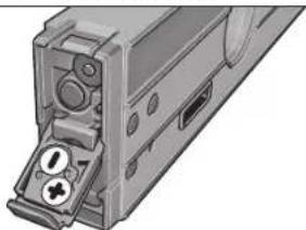
TnRte TnAnKpO 8yva va ByeT no nOki Kaumnpapiaqatoc 17.FuprTe nBiba puHianC 9va va puOioTe no nOki Kaumnpapiaqatoc etai, wote ndiaboojn rnc Acivac AieKe v npaaMolre Te unu nd Opiop enmoadvei a, avloya, n emUunrn kAon va eapavntluc nun peponcb.
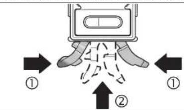
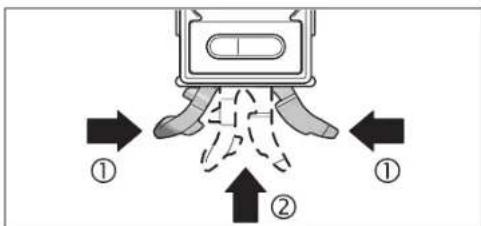
Ia va epaareTre xupkmuavao kaumpaplaatoc npeneva eioiyere ntoepeyaleoepanrncnlo16kaTto ndoaiuapapiaotoc 17.1 auro ouimtctc ta duo kaipataou moboo (1) kaakolawocayctro nod16toepayaleoepanrcc(2),pevxa oakoiote ot aoapoe. Ia va eoyate to noia kalmpapiaqac 17 0thane nauiuc to daokm 10.
Σερεωηστο τριπόδο:
-0c0tCto cyAio 14"unO60nHctponc 18 cndw an NkAa taayac alaaivc To Tnpoo26 n endow e ev npnoo an to kovE emopio. Biaute to epAio teponnc nT Biaotepewnont naKaoTaeiaoc aalnyic.
Lepewon pe paayvnt:
Oeote to epayelo eponc me to paWnt 14 enva o eva enapkau paWntoepvo ekaptma.
BeBaWeBeIOnToepAeioMepTnOcivaoPacocpeewpeo. OArToepAeioMepTnOcBvCvAoPaeocOePcPcEvoMpOciVAIOcKCAVAIOaJIaEOeAcNkAOIOAIMOAtO.ArToepAeioMepTnOcMeiOmepoVIAUMOOTNEJNOtIoIOVAPOKaAoeiAeLcNtue.
Tepeowneuavrcotepeoos(βaeneikovcC)
IpiErc nucuvcn 25 npnuvtac tcc mao nucnyocic uva 15 kai orpeowate to eayakeo pertponc me touc uvece opeewan. oeunvnc ne katoia aalnapouvoa vntkejeva. Bebaowoeite ot n autonpoopoun ookouou ouva ecimocotci kai kawocn cnaov otuv apeuwanc. Oav on owawve cival aeelmoll, tote nepaote rouc uvece opeewan. meaa on tc nywneic uva Te nlae nkeupnpoc ta Eekw kuiie touc akqum qopa ypu ano to eyawce oipponont omcaivatantoi evkova. Oav on owawve cival xovptol o uvece npene va nepaotouv meo ant ic nywnyoeic uva te nly ea nuepupoc ta coea.
Na aapalite To epyaleio pertnnc navtoe ka me tou duo auvtce otepeoan kai vaebaoote on ouvretc elvaep otepevoI. H uovmuykayopncnTW uivantv 25 ekaptarma ot m ouotraon rou uikou oTo omoloexovtpeowelXaapa opeeweva


EMnyk@83
epyaleiae npnncmopei va naoov kai va unaoov zna ta iia na pokalaeouaAeczneie.
Mny apioe raiia va xpnapomnauov avemtnipra roupavrec stepewc 25. Mnopei va autotpaumamotou vpuouv madvnc otepewc
Evepyooinan/Aneepeyooinan nnc metpnnnc kkannc kntnc oobvnc Ta va eeyopnoioe t mptpon klanc kai ny obovn ranrto nAnkpto ON/OFF 2. To cypakicmu npncpckl aon Acioupyla Metponk klanc pe oradrapnveviok aneio.
Tua anevepyomouoetn metanon kalong kai nV oovn mntote naia to
'Orav ro cyayacelo metanong devnarnBel kaveva nhtko yta 30 min neipmou kai n kalon dev meraBnEi meepooe npo an 1,5o rote aenepeyomouovtna n metponkian kai n oboyn. Eto npotareuertan n marapia.To Keiep npaqucv cvcnpcao.
EvepyonoinAmevpeyoonoinouieep
Tia va evpyonouaTe To AteCp wthate To mKtpo ON/OFF 19 om eon a.
Mny KATcUOvETe NtivAkriva AIEp eNAdV Oe npodownta nKauynuN KoiTae oIioC/n IooaOny AInriva AIEcp, AOpn K ano peYahn anoTaon.
Iva vanevepyononeo ce to aeep oohote to naikpO ON/OFF 19 0an 0
Na un apnve To epyaleio mepnonc avemtnpno Tov to Aiecp Eiva eveyponnoe Kai va anevyponoite To aeipotr realeei Te npohon Tou pyaeaiou mepnonc. H krtiva Aiecp npopoi vua Tupauocu Tuyov napcuipokcvapodaum.
Na anecpyonoicte to aeCp oav dev to xonnoioute. Eto eokovopelte evepyia.
AALLAY movadac metponc (Bleme ekova A)
Avn aon mnpetre va emeEte ovmao an oovdec pe tonnc * 99Kai mm/m. Tauta natiOnc aaanlAnAto nAnkpo AAnyn yovdoov meton5xen eniunmtnovda ptonocva eapavotore onv evocienf H. Hpexouao tuih ptononp metopenteta autoqua
H pOthmT mocovadac uctponncnapuvcin 1ia bav ctrec to cyalc0 utpnonoc aeletoupyia kEKTOC AEITOUpyiac.
EvpeynoinAnAevepyooninTouakouotkoohpatoc
Me NaIaKIO AkoUKO kOma 1 mOpoei va eevpyoHoe KAI va anepeyOnouieTe AkoUKO mOra. Ova To aokouTko oma eiva cvpOyoNcoVTo mOthov cpavl cTn vocic n
Hpouon Tou aououkou ou matooc napayevotav theo eoe to epyaleio pTponc oetoupyia nekoc toupyiac.
EvEeEgTnuepeToonncKaIBoOnmuTaEuBuypuPmionc
E Kabe Kivnou Tou eayaleou eepnang evneepawetai (npaaapoei) n tuiu ptonnc. Meta an oxetik peyaeac metakivnieicou epyaleoi uonpionnc nepevee ie nyn avvwoon nnc nucetponnc expun v a nuaic va paiaabactar.
Avaloya mc thccon Tou cayaiou utpnonnc n tui kai mowda ma pnonc aty oovn nepiortepoovtai kata 180."Eto npoeite va aaywaaete eukola nTv evdeakokun k av epyaedae me to epyaiao utpnonn naaw ao Tokepa oac.
HevBn Bonnauu euybupaunoc a deywe otmy oboynpoc noia kateu Houn npne va KaBei to epayaei metprnoic vya enteuehEn n Ebioukouevn tni. Hemaiokouevn tni eivatotarapetephoiec Opovmoc n avloya, nKobetoc. 2t NteoupviaCyopny anoNkeueyu nui Kai ne ppiwno mraBnEvIOU, uDvEVKOOnIeuO uonBnKeuEV uNDVKOOnIe.o
Moi eneuege n emiakoeynr npn oynouv ra bEn ruv Bonnauo euyuypauioc a kai, 10r to auoutko onua civai evpyonoiev, aoayetai evacagrih xioc.
OBJ BUCH-1628-002.book Page 92 Monday, August 27, 2012 12:22 PM


92 | Türkçe
Bosch San. ve Tic. A.S.
Ahi Evran Cad. No:1 Kat:22
Polaris Plaza
80670 Maslak/Istanbul
BoschUzmanEkibi+90(0212)3671888
Isiklar LTD, STI.
Kizilay Cad. No: 16/C Seyhan
Adana
Tel.: 0322 359 97 10
Tel.: 0322 3591379
OBJ BUCH-1628-002.book Page 100 Monday, August 27, 2012 12:22 PM


100|Cesky
Bosch Service Center PT
KVapence 16
692 01 Mikulov
Pocchra,129515,MockRa
Yka3aHHIto6e30nacHOCTH

Aa 06eueehn 6e3oancho Hnaekho npabtbc H3mePteAebHbHnHCTpyMENTOdoAHHbStb TPOHTAHbHcOBaOaBtBaCBe HnCTpyKun.HNKOrda DOBOATE PpeayPiPeAteAebHbTaobHKn Ha3mePteAEBHom HnCTpyMeTO AO CooTARH Hey3HaaeMoctXOPUIO COXPAHITE 3Ty NHCTpyKuHIO.
BHMMHNE-HNTOA3OBAHNE ApyrHex YEYOMAHyTBX 3AcBc 3AEMHTOB YYPABAAEHN HPERAYHOBOAHN HANAPYHX METOAOB KCAIAYATAUM MOKET IOBeprHyb Bac OTHACHOMY DA3DOPOBBN 3AUYENHNO.
3MmePHTAeBHHNHTCPYMEHTTOCTABAHETC TpeaDyPTAEHBOH 3aBAMKHO (Ha cTpaHnue C N3o6paKeHHem 3MMePHTAeBHO HHTCPYMAHTOK3a3Ha TOHOpEMO2 21).

OBJ BUCH-1628-002.book Page 120 Monday, August 27, 2012 12:22 PM


120|Pycckn
He pHMeHREA3ePbHE OOKB KBAeCTBE COaHEHbIX OOKOB HAN B yAHOM ABXHEH. A3ePbHE OOKH He AOJIO NHOH 3aOHHTO ByabTpaHOAeTOBOI HAUYcHIN YHXdAJOT BOCPTPIHNE KpacK
Pemont Baewero M3MepHrEAbHOro HcTpyMeHa TOpuyaTe ToAko KBAANuHPOBaHOHMy TepCOHaAY, HcTOAByr TOAko OPnHnHAb Hbe 3aTachyaeacth.3tHM o6ecneHHBaETCa 6eotnacOCTb NMePHTeABHOHcHPTpyMeHa.
Hepa3pewAte DeTnIOAb3OBatCh Aa3epbHM HMepeTbHbIM HHTCPyEMtOM 6e3 Ha30pa. OHMyOTy HeMbIaehHO OCAenHbIb AIOAEJ.
Hepa6oTaTe c3MpeHTeAHHMHNCTpyMeTOM BO B3pboBOOACHO
CpeAE,TO6A30CTOT TOPOUHX XAKOCTE,RA3OB NTHAI.B
KHMpeTbHOM HCHPTyMeHTe MOYr Opa3oBaTcR NCKpy,OT KOTOpBx
MOKETBOCTIaMAHEHITCB TbA HINIAPb.

He pactoaaarte H3mpehtaeBbHn HcTpymert
6BAa3H4KAPHOHTMyAORTopa.MaHTb1 14 c03aHOT
NOAE, KOTOPOE KOETOpTPOHATEbHO TOBAAHTb Ha
fhyHKUHO KAPHOCTHMAYORTopa.
AepxHHe HACTOIM K3MEPHTAEBHb HHTCPyMeHTBdAHOT MATHTHBHX HOCTEAEAAHbIX NYCBTEAeBbIX K MATHTHBIM IOAMnPH6OpB. B03eCTBHeMaTHTOB 14 MOKET PnPBcETN K Heo6pTmHMIOI TPOTe AaHbIX.
OttcaHne IpoAkyTa n yCAYr
IIOKAYNTA,OTKP0HTePACKaADHYOCTPAHUYC HAAOCTPAUHHM NHCPTyPMEnAIOCTABAHTEeEOTKPbTOn,INOKaBbH3yauTe pykoBOCTBO TO KcNcYATAUN.
TIPMHENHNE TO Ha3haeHHIO
H3MePteAaBbHm HnCTpyMeHT PpeHa3HaueH AaTo4HOro N3MepeHnI INepeHOCA yraOB hakHOa.
V3MePHTAeHbI HcTpyMeHT ONTHMnPOBaH AAR HCIOAL3OBaHH BHYTPN TmEeHH.
H306paXeHHbIe coCTaBbIe yactn
HymepaI IIEpCTABAHHbIX COCTABHbIX HAcTeH BblIOANHe H0 H3O-6paKeHHIO H3MepeTAEbHO HOHCTpyMeHTA HA CTpaHHUe C HAAIOCTpaHHM.
1 KhoNka 3ByKOBOO CnTHAa
2BbiknouatehH3MepeHHraHaKaHOHaCnAe
3 KhoNka H3MeHHeHH HyEBoH ToQKn «Alt 0°
4KhoIIKaKaH6pOBKn/YbEaHueHHN OTo6paKaemOrO 3HaueHHN KALB
5KHONKAHMCHEHNAHNNHbH3MPCHHYyMHBCHNHO6paXaEMo 0haeHNn a /% /mm/m
6 KhoNkaФнсИрОвАнг/пepeHOCa 'Hold/Copy
7 Kpbiika baapereHoro oTeKa, h3MepeHHe yraHa KaHOHa
8KhoKaAaBbTnBaHnHnBeHnpOBOHNOHO
9IOCTnPOBOOHHHBHNHTHHeAMPOBOOHHOKKN
10 KHTKa AAR BTRHbAHn HNBaHPOBOHOH HOKKN
11AHCnAeH
12Topn30HTaBbH BATEpTAC
13BePHTKKaAaBbHbBatepTAC
14MaHTbI
15IpoynHaTpaepemHb
16 Hoxka
17 HnBeAnpoBoOuaHnOxKa
18He3a0noaWtaHB 1/4
19 BbiklOaTeAaIa3epa
20 Kpbuika 6aapenHoro orceKa,aaep
21 OTeBepTme DAA BbIXOa AaBepHoro Aya
22 PpeaytppeHteAebn TaabHkaa3epHoro 3AyeHH
23 CepHHbH HOMep
243aunTHHueXoA
25KpeTeKxHbIpeMeHb
26 LITATIN
H360469KHe HbN OHTHCaHHbE TpHnHaAeKHOCT He BXoAHT B CTAHApTbH 1 KOMTAEK NTOCTABK.
AeMeHTbHnHnKaun
a BcTOMOrataeAbHbIe WtPhXn AAR BBiBepKn
bH3mepeMe0e3aueHHe
cHHAKATOP3BYKOBOROCHTHA
Dppeynpeekdene npa3paKe6aTaapeek
eHdHKATOP H3MeHeHHH HyeBOH TOOKH
fEAnHHMaK3MepeHHA


Pycckn | 121
TexHHueckne daHHbIe
BcTaBA/3aMeHa6aTaapeekAAnAa3epa
OTKINHBE KPNKU6bATEHORO cTeCA 200BCTABTE6bATEHKN.1Pn3TOM CAEDHE 3a cObMOAENHOIAHOTCH B COOBETCBN K CIO6paeHNHMA H BYHTNEH CTOPHOE KPNKU6bATEHORO cTeCA.
ECAHAA3ep6oAJIHE CHTC,6aTapeKHNHYXHO 3aMeHHb.
Bosch Power Tools 1618C0062X| (27.8.12)


122|Pycckn
Yka3aHHe: PtpyipkXeHne O paaepae 6batapeek dHaMCTTae He oTOHCITCR K a3epy.
063aTeAho BbKaHouaHTe Aaeppepe 3ameHO8 SaTapeek. BkAouHHIO TO HOCTOPOKHOCTN Aaep MOKET OCAENTHBYAEOBekaBcERd aMeHHIte CpAsy BCE TpEHa3HaueHHBe Iae paBOtBu AaepaBatapKeIN. NcToA3ByIte ToBoKoBatapKeIN ODOHOHOEMKOCTbIO.
Pa6ota c HNCTpyMeHToM
3KcTAYataaH
3aunuane H3mepeAebn HNCTpyMeHOT O BAan n npMbx COAHe4hIX Ayei.
He ToaBeprae N3MePteAahbHn HNCTpyMeHT Bo3dEChTBHO 3KCTpeMaahbX TemPeTaty N3MePteAahbY HTepeAoh B VCAHOTCH, He OCTABAHRe ETO HAATAAbeHoB ePMAHInue. TpR6OaBHx TpePenaax TemPeTaty ChauHaA DaJIte N3MePteAehbOMHy HNCTpyMeHTy CTAbMHNPOBaBT CBOO TemPeTaty, PTEKeAe WMHAnHAtb Pa0tAtc b Hm. KCTpeMaahbYe TemPeTaty N3MePteAehbHO HNCTpyMeHTy OTnPAteAho BAMNT Ha TOUHOCT K3MePteAehbHO HNCTpyMeHTA.
H36eAHTe CHABHbIX TOAOKOB HADEHN H3MepHTaBHOH NHTPYMEHTA. TIOCA EAHCBHX BHEUHNX BO3AEHCTBN HA H3MEPTAHbH NHTCPYMEHT, INPEKDe cHem TPOAOKaTb paObaTb C NHTPYMHTOM, IPOBEPTE ITOOHCTb (CM. KND24).
CaePepKTe OTOHbIE NOBEXHOCTN H3MpeHTeAHO HO HCTPYMENTBA HCTOTE H BEPERTEHXOT COPTCEHN H YAAPDR. P36 HAN DeOpDMARMYOTPNIBECTN KIOUOKAM M3EPOHH
YcTaHOBka/3aKpeTAAEHeH 3MePeHTeAbHoTo HmCTpyMeHTa
AHRN3MEPBNHNRHEPOHOVAI HAKAOHAMOXHO RETOBKO PINTCTABRTB N3MEPBOHHN INHTCPYMEHTKIOBEPXOCHTH KAACTb HAEE,HO H NTOBAOTAEHNNIECIOCOBJYCTAHOBHKJ3AKPEITNAHINHCTPYMEHTA.
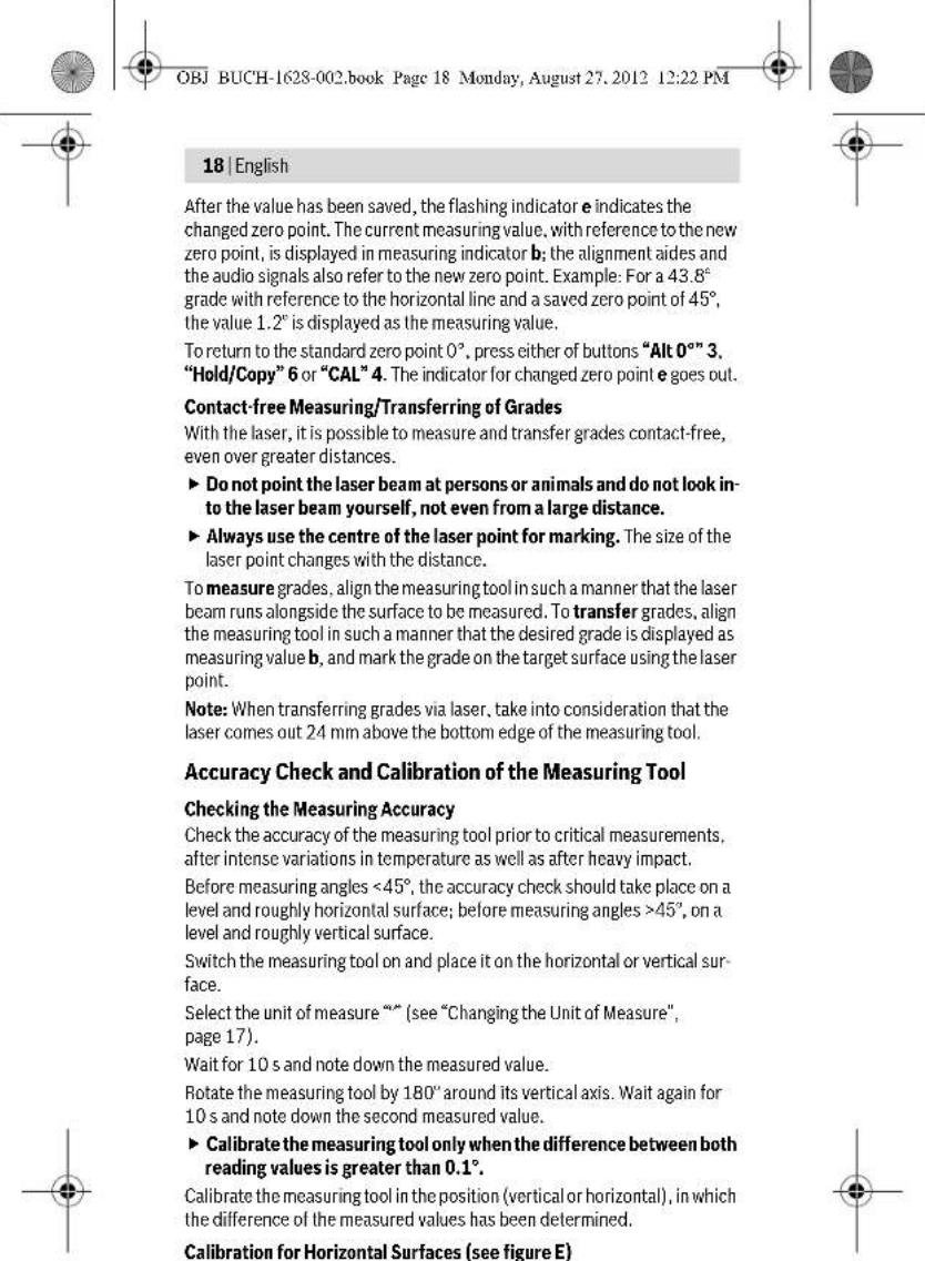
YCTAHOBKA TPN NOMOUI HMBEAMPOBOOHMO MEXAHKK (HApN, HA HEPOBHM OCHOBAHNN) (C.M. PNC.B):
KopKO HAKKMHTE HA HOKKY 16,HTO6bI BtHTHytB ee.HaKMHTe HA KHOKNY 8,HTO6bI BtHTHytB HNBEAMPOBOHYO HOKKY 17. OTepyAHyPTe BcCOTy HHEANPOBOHOU HOKKN TYTEM BPAEHNIOCTMPOBOHOBONHBA T9AK, T06bI A3EPBHy AUY PPOXDN BAOb H3MEPNO MTOBEPHOCTMN HNYKHB yTAO OToBPaKaACB N0Ae DAA H3MEpeHHORO 3AHueHHN b
ApaBt63 HHEANPOBOHOH MEXAHKH CHOBa CnPbAte HOKky 16 HHEANPOBOHYO HOKky 17 AaTTOCOKMITE Obe cactn HOKKN BMEcTe (1) H3aTOAKNHOTKOXY 16 bMAePeTbAHbH NHTCPyMeHT (2), YTO6bO hOA aHTeTAMBO BOIIa B3aETeMeHe. YTO6b cPiPTab HHEANPOBOHYO HOKky 17, CaBHbTe KHOKNY 10bCTOPOHy
3aKpETaHHe Ha WtTaTHBe:
YCTAHOBITE H3MEPHTEALHINHTCPMENTHE3OMNOAHTAHB1/4"18
HA6bCTPC0BcEMHYTAACTHNYATATNA26MANObHHORoCPOUHTAHBA.
3aDHHKCHPYTE H3MEPHTEALHINHTCPMENTCTIOMOUBIOKPENEXHO
BHNTA6bCTPC0BcEMHOITAACTHHL.
3aKpeTaeHHe TpH TomoUH MarHTOB;
- PIPCTABUte 3MEPHTAEuH HJTHCPTYMEHM TAHMTAMH 14 KIOBEPXHOCTN, OBAADAKUO DAOCTAOYHBMAMARHHTHBMH CBOBTABM.
PioBepBe TaekxHocB 3kpeAeHHN H3MePteBHO HOHTPY MHeTb. HeaEeKHO 3akpTeAHn H3MePteBHO HHTCPYMEHT MOKET yNaCTb H paoHbB Bac HA APyHX NIOe. TaeHHe YpeBaTO NOBpExeHEM CamoHO H3MePteBHO HOHTCPYMeTA H ApyHX PNDMTOB.
3aKepeTAAHHe TpN TomOuIN KpTeKExhBIX pemHRe (CM.puc.C):
IpoedeHbTe KpeTekHbPe pMHN 25peepaoyuHbAaPemHn15 n3akpemHte KmepHTeBbHnHCTpymET HA Tpyo HnTOdoBHOMTPeAMe. CMeTte 3a TEM, TTObblactexKa AHNYka HaKOHKe KpeTekHOPO pMHbBbMa a3acteHYta. PIni ToHKTHTYbX BCTABAHRe KpeTckHbte pMHn BIOyUHHbDAraPEMHe rAaKO CTOPHOHOHApkyHn3abopauHBeNTxE He paeBpOYrKHMepHTeBBOHOHcTPTMeHa, KaKTOkAsHo HnPCHyHke, TpH ToACTbXpyBCTABARNe KpeTekHbIe pMHn BIOyUHHbDAraPEMHe rAaKO CTOPHOHO BHyTpB.
Bcerda3akpenIHTe3mepTeaBbHbHcTpyMeTHAByM KpEeKbHM pEmHM H TPOBpeHTeHaEDXHOCTb KpeTAeHHa CnA, c KTOPOH pKexEHb PMeHS 25yApckBaHcTpyMeHT, 3aBNCHT OT MATEPHAA, K KOTOPOMY OH KPEITHC. CaA6o3akpenHbH bHmHcTpyMeHT MoKET COCKOa3Hyb H NOBpeHTbCR HA NIOpeHTb ApyTHne PEPAMETb.
He daaBte TaTmIOAob3oBaTcKpeTeKHNbMnpeHMn256e3IppcmToPa,EtHMOrTIpHHuHTbCe6eTpabMbIKpeTeKHNbMnpeHMn.
BkaKouHHe/BykAIOUeHHe H3MepeHHy rHa KaHOHa HAcCTaEer
ABAKIOOHEHRA M3MEHPENYI YTAH HAKHOHA HACNIMAHAKMITE HA BHKIOUOATEB 2. N3MEPENTEBHLHCTPYMENT HAXAOHTCR B PEXHM E M3MEHPENYI YTAH HAKOOHCO CTAHADPHTHHYAEBOY TOKOH.
AABBbKAUOHHM3MEPOHNRYTAADKAHOAHNACHTAERHAKMMTE HBAKKAOUATEAE2CHOBA
EcaB TeueHHe pnp60.30MHn.HaH3MepeTaebHMn HcHcyMeHTe He bDeK AHKMTHACBHAKHX KHOTK yTOA HAKAOHa H3MepeTaebHO HOHCTpy MEHTA He H3MeHmTCB 60aeem HA1,5°,H3MepeHne yTa HAKoHa HdCTAcI cUeBIO KHO TcBAtepn ABtOMATuCckN BkKIOaOTcR. Ha paBOy A3eepa 30 To HE BMnER.
BkaioyeHMe/BbikaioyeHMeAa3epa
AABKAOUHMAaepaHaKMOTe HA BbKAOHATEb 19 HcYTAHOBHTe E0BTOPOXKEHEb
He HapabAAHte Aa3epbH bAUY HAIOAE HAN XMBOTbIX Hc CMO TPTHE CAMB B A3ePbH Auy, B TOM YCAE H C 60Abuoro pACCTOHHM. AAR BbIKAOUHm Haa3epa HAKMHTe Ha BbIKMOUaTeAB 19 HcYTAHOIBTe eRO B TLOXCKHCn e0
He octabaahe KmepehtbHn HCTpyMeHT C BkAooeyHHBm Aaepom6be3TPNCMOPTb H BbKIOaHae3PteACoe Hcnoa3BOAHN. AaepehHMyMQeTCAeTNAPyHXIAOy
EaHaaep He HcIOAbaeyTa, BbIaOauHte erocaeAbO KOHOOMN JhepHH.
Cmeha eHnhi H3mepeHH (cm.pnc.A)
B Ako6e bpe mEHNHNI HMepeHHM KOHO TEPEKIOHTb Ha a",%N I MM/M。Aa 3TOI HOHMAHNE KHTOKNY HMEHEHNE HENHUNI HMEpeHHI 5 DoTExnop,POKA HA HNKATope f HOTOBHTC HYKHAR ENHUNI HMEpeHHI. TekuJIe HMEpeHHOe 3aHHeHNe ABOMATNUeCK NTEpeTHINBaCTc
HaCtpoKa eHINHbI H3MepeHHaCOxpaHaeTc TIPN BbIKAOeHHN BKMIOeHHN K3MePnTeBbHOrO HcHTpyMeHTA.
BkIOUeHHe/BbIXIOUeHHe 3ByKOBOrO crHaHa
C TOMOUI KHOKNK 3BYKOBO CHRHAA1 BBI MOKETE BKAIOAHTB BUKKAOHTB 3BYKOBO CNHAA. PBN BKAIOYEHNOM 3BYKOBO CMHAAE HA DCIIAEIE OTOBPAAXAETCR.
Hactpoika akcytcheckoro CnHala coxpaHReTc np BBKIOUeHHN BKAIOUeHHN N3MePHeBbHOO HHCTpyMeHTA.
OTo6paXeHHe N3MepeHHoro 3HaueHn HBCtOMorateAbhble Wtpnx DA BbBepK
PtpKaKaOM TepeMeHenn H3MEpHTeBOHO H3cTpMeHTa H3MepeHHe 3aHcTeHne AkyaA3npyETCH.PtnbOaBmIpeMeCHeHH3MeptHeBHO HcTcPHeTaeA CEAeYt BkOaA3b Tpk0a3aHeH3MeHmEroHO 3aHcHHe.
B3aBNCMHOCTHOTIOAOXEHHIN3MepHeTeAhoHOTHO HnCTpyMeHTA3MpeEHHIO 3aHueHHNEIeHNHUA3MpeEHHNIPOK3aJIbAOKTCaHAnCnEeBTOBEPHYOM HA180°pOAOxEHHIN.5laOoapraTcMOyNPOKa3aHneMOKHO CunHtBaTbHnPiP paboTe HADTOBOH。
BCTOMOTATELHBIEIITPKHXANABBBEPEKHNHADNCIMEEH3MEPHTAEBOHOH NCTpyMeHTA NOKAbaIBaIOT, B KAKOM HATpABAHENHNHYKHO HAKOAHTB NHCPTyMENT DAOCTKENHNNYHKHOHOHNAHYYHKHO3AHAHEHNE TPI CTANDAHPOTHM3MEHENHN-TO 1060 BOPTOPHOHNTAIBHAA, Hb6 DEPTTKAIAHBAHAAHHN,B pEKHMNEpeNEHOCA《COPY》-3TO COXPAHEHHO B NAMTH AHAHEHNE,A TPI M3MEHENHNHYAEBOTOHK-COXAHPAHNBA N BAMTHYHAEABJTOKA.
TIOAOCTKHEHNHYHKOHTHOHAHBNCTPEAKNBCOTMOFATEbHBxWTPHXOBDA BUBEKPNAHCSE3AOT.IPIBKNLOUYEHOM3BYKOBOCMHTHAEDOANOAHTEBAHO TIOAEETCETHPDEPBIIBHH3BYKOBOCHINHA.
Pexnmbi h3MepeHH
ΦHKCNPOBAHNE/πepeHOCn3MepeHHOro 3aueHHa (cm.phc.D)
KhONKa《Hold/Copy》6HMeTeABeΦyHKUH:
-ΦHKCHPOBAHHe(HoHold)HMpeHHOrO 3aueHH,AaeE cAH3MepHTeHbHmHCTpyMMETB6yEt NOcAE 3TOgTeABHyHT(HaTp.,ECAN MEPHTeHbHmHCTpyMMETHXoADKTBC TAKOMTOAOxEHHN.B KOTOPOM TYDHOIOPOHTAtb OTOBpaKaMeMB Ha DCIIAE DAHHBeJ)
-ηepehoc(Copy)H3MepehHoro 3HaueHHN.
DyHKUHa aHolda
ΦyHKmR eCopy:
HAXMNTHEKHTKYHOld/Copy6.Tekyuee H3MEpeHHoe 3aHeHne b
ΦHKCHPYETHa H3CTAee, BCE ΜEEMHTbI DnCTAee, KPOMe H3MEpeHHOT
3aHeHne, MfAOT.
AaNpeKekOJIeHnB aEeKINb cOpBy hAKNTME HkOHTKY 38yKOBO rCTHNAa1 A,AAHAAJHOBOI hMePEHJI-HA KHOTKY eHOLD'c6y.
BBAOKHTE 3BKYOBON CNTHAA (CM. dBKAIOJHEHME/BbIKIOHHe 3BKYOBOTO CNTHAA, ctp. 123).
-HAXMMATE KHTOKY AHold/Copy 6. TeKUYe H3MEpHHeHO 3HAeHHHE COxPAHETCR BAMTHP. PaaAaTcER KOKOPKT EByKOBO CHrHa, HNNKATOPBcIaHHNbH3MEpHnF h BYKOBORO CTHHaA cMHRtAKT.
- PnHbMnTeAHoNtMepeHHeBHe 3hAeHHeMHMOHO CKoppeKTHPOBaTb THepePteHcOOM: HxMMrE KHOHTKY YBEaHHeHHo OTbPAkaeMaero 3HaueHHN4, 0TObeYBCaHHTb COxPaCHHCHe B TaAMH 3HAeHHc; HxMMrE HA KOHNy yMeHbUeHHo OTbPAkaeMaero 3HOAHvHH5, 0TObeYMeHbUHtErO.
IpiCTabte IImePHTaBbH HtCtPyMeHKT N BoepxHOCht, HA KOTOPYIO Hb6OxADIO TEpeHECTI MImEHPHeOH 3aHcUHeH, KaK TOKA3AHA Ho
Bosch Power Tools 1618 C00 62X| (27.8.12)
3aTeM B TeneHHe NpRbA.2 CApKHTe HAKATOI KHOITKY KAHIbPOBOKN aCAL4, noka HA DCHTHE HA KOPTOKBE PBMER HE OTObPAHTCR CAL1a.HzMEPENHO 3AHQHNE 3ATOM 6yDT MRTHATb HACHTOE.
3 PioeepHnE H3mepeHbA hHnHcPmEHn H 180 BOKpyBepHH KaHOH OCH TAK,HTO6b BATEpIAC CMOPTAE BBEpX,aAHCIMe11 XAOHAcH AHTPOTHBNOANOHKOnOT BaCtOPHO. PIOADKaMeT 10 C.
4IIOcE 3TOrO eue pa3 hAKMHTe KHOITKy KaHb6pOBKn cCAL>4.Ha HACITME HA KOPOTOKE BPEM OTOBpaKaETCR cCAL2,3ATEm HA HACITME OTOBpaKaETCR hMepeHHOE 3HAue He MMraIOoee). Tenebp hMepeHTAabHyn HHCTpyMT EAHOBO tKaHb6pOBaH DAHHO ONTOPOH TOBepXHOCTN.
10cne 3TOI H3MEpTeBnHn HnCTpyMeT CnAeYETOKaHbPobAtd AITPOTHBOAOXHOIOTOPHOI TOBEPXHOCT. AIA3TOFO TOBEPHTHE H3MEpTeABnHn HnCTpyMeT BOKPYT TOPH3OHTaBHOH OCH TAK, YTO6bI BATEpTaC 12 CMOTpeBAHN, aAHCIIAE 11 BbI o6paueH K BaM. PIPAoAIOE H3MEpTeABnHn HnCTpyMeT K rpo3HOtAaHOH TOBEXHOCTn. IooKAnTE 10 c.
3aTeM B TceHNE PnVbA.2 CdEepNHE HAKATO KHTOKY KaHbPOBKNK CAL4, 4, NkA HcHcIeH Ma KOpOTKe BPEMe HE OTO6pa3HTCRA CAL1. HcMEpeHNOe AChAHcHHe TATE bSyd MmTtRnA HAcHcIEe
TIOBEPHHTHE NAMEPHTEAbHBHnHCTpyMeHT Ha 180° BOKpyr BEpTHKaABHOH OCH TAK,TO6bI BATEPcN CMOPTEA BHN3,A dHCTAe 11 HAXOxAACAH A hPOITNOBOANXOHOT BAC CTOPOE. IAOOXATE 10 c.
TOcNEOTOROOTABHAXMMTEKHOHTKYKaAMbPOBKNICAL4.HaANCTIe HA KOPOTKE BPEMAOTOBAPXAETCAICAL2.3ATTEMHAHNCTTAE OTOBAPXAAETC H3MEPENHO3AHEHNEY(yke HE MNAIOUee).TeNepb H3MEPHTAEBHHINHTPYMCHTBAHOBOOTAHNOBPOBaAH 06BXN ROPH3OHTAABHbIXOTOBPHX NOBEPXHOCTE.
Yka3aHHe: ECAH N3MePHTAeBbHb HIN HCTpyMEHTO BSPMA OTEpaJIH ③ N ⑦ He b4et NOBepHTBOKpyrIpeCTABEAHHO HA pCHyckHEOc, KaAN6pOBKa 3eABPeBaerCa (Ha dctMee He otobpaKaTeac cAL2a).
KaAn6pOBA BeptNkAAbHbIX ToBepXHOCTn pMaerHaHr (CM.pHC.F)
TIOBEPXHOCTb, HAOKOTOPYBOBycYtAHABAMBAeTeH3MEpHTeHBHnHH-CTPYMHT, HeOADKHO TOKAOHNbTCrOETBePTKaAN6oAee yem Ha 5°.ECAIOTKHOHEHNE6oBbue, KaNbOBpKA TpeKpaAsTcRnHa DnCtAeeOTOp6aAaeTcRn→
BkIOHHTE K3MPEHTBHL HHTCPYMEHT HTPCTABTE ETOK BEPTKAAHBOIPOBEXHOCTTAK,HTO6bI BATEPITAC 13 CMOTPEA BBEpx,a AINCTAEI 116BaOAPaENK BAM. IIOQXATE 10 C.
3aTeM B TcHHeN Pn6A.2 CApKHTe HAKOTK KHOITK KaHbPOBxN aCAL4, noka Ha dCtIe HA KOPTOK BpEME He OTObAP3TcA cCAL1. 3npeHepNO 3aHcHNe 3ATm 6yEt MMRt Ha hCtIOE.
310OBepHHTNE IMePHTbAIBN HHTCPyMHT HA 180BCKpyR BEPTNaBHON OCH TAK, YTOBbI BATEpIc CMOTpeBBEpX, aHINJIeN 11HAXOJHNAI HTOPITHBOANOAOHXOT BAC CTOpOE. IIOAOJXTE 10 c
TOCAE TOTO EUE pa3 HAKMTE KHOIky KaAMbPOBKN cAL>4. HaNCTMeE HA KOPOPTKOE BPEM OTOBpaKaETcR cAL2x.3aTeH Ma NCHTMeE OTOBpaKaETcN3MEpeHHe 3HAeHHe (yKe He MInraIOUeE). Tenepe N3MEpHTeMbHb INHCTpymEt 3AHOBO OTKaAMbPOBaH DAaHHOIT OTOPHIO TOBepXHOCT.
TOCAE 3T0R0 H3MEPHTAEBHHHINTPYMNETCAAYETOKAH6POBABTAAI TPOTNBOLOXHOH OTNOHOIOBEXHOCT. AIA TTORO NOBHPHTHE H3MEPHTAEBHHINTPYMNETBOKPYTROPHOHAIHOHOCTAK,TOBbI BATEPNTAC13CMOTPEBAHN3,AHCNAJ116bM O6paueK BAM. PnCTABTE H3MEPHTAEBHHHINTPYMNETK BEPTHKABHOH BOPBXHOCT. IIOAOXNTE 10c
63aTeM B TcEHHe NpHbA.2 CdEepKHe HAKATOI KHOITKY KAMHOBOKN aCAL4, noka HA dHcJIeH Ma KOPOTKO BPEM He OTO6pa3HTCn aCAL1. 1HMepeHHoe 3aHHeH e 3aTeM bOyAT MRHTa HAcHIEe.
⑦ ToBepHHTe H3MePHTeAaBbHb HcTpyMeHT Ha 180° Bokpyr BepTHKAbHbOH OCH TAK, TcB6b BATEpC MTOPTEA BHHA, a DcTAeB 11 HAoDAHACr A hTPOINBOOAnHOJOT oBac CTOPOE. IoAoXdTe 10 c.
IIOcE 3TORO ONABHAXMHTE KHOHTKY KAANbPOBKNICAL4.Ha HnCTMe HA KOPOTKOE BPEM OTObPAaETCR CAL2.3ATTEM HA HnCTMe e OTb6pAAeTcN hMEpeHHOE 3AueHNE (yKe He MNaIooee).TeNepb NMEpHTAEhBHy INHCTpyEMT 3AHOBO OTHAH6PBoAH DABOBEX BEPTTKAabHbX IOHPbHX NOBEpXHOCTei.
Ykaa3aHHe: EcaH NmEHPHTAeBbHb HnCTPMyENTo BPOEM OTePAUJIIN ③ H ② He 6yIeT NOBpyHT BOKpyr IpeCTaBaeHHo HA pucyHKe och, KaANbPOBaK a 3abeBPeAeaer (Ha nctMeer He otobpaKaeec aCL2b).
Tex06caayxmbaHne H cepBnC
Texo6cayXHBAHHnOuHCTka
XpHAnHe HIEpeHOCHTe 3MHePteBbHbN IHCTpyMeHT ToaKbKO B TpIaAraouoEChMa3uTHOM XeAE.
Cadepkhte H3MepHTAebHbHINCTPYMEHT NOCTOHHBOYHCOTOTE. HIKORAHeNppykaHTe H3MepHTAebHbHINCTPYMEHT BBOyHANAPYTHE JAKKOKTc.
BbTnpaIe 3aepn3HHeHH cyxO H MArKo TpAikko. He nCIObayIte HNkaknx ONUIauOHX CpeCTB MAN PACTBOHPTEAEJ.
Bosch Power Tools 1618 C00 62X| (27.8.12)
YkpaHcbKa
Bka3iBkn 3Texhikn6e3neKn

IpoaHTAe BcBk3aIBKn I aotpMyteca ix, 0o6
IpaObathn 3 BMHIpokBaABHM pHaAdOM GbeTHeHO Ta
HaiaHIO. HIOAM He AOBoBeTe NOpTepeXyBaHbNt TabAHuK
KN HaBMHpOBAhOMy IHcptpyMeTI AO HeBNI3HaHNOCTI.
O6PE 3SEPIAITEIX.
06epexho-BNKOPCTAHH3ACo6IB 06cayrobyaHHn i HtPOBHAHn, 10iBDI3HbTbC BIA 33A3HueHHN xui iNCTpyuui, a60 BHKOPCTAHHn DO3pAlEHx 3ACo6IB y Heo3OBAeHH nCTOci6, Moxe pN3BOAHn DO He6e3neueHHx BHyxBtBNPOMHOBAHH.
BAMIPBOAHHI INCTPYMNT OTOCTAACTCB 3 TOTEPKBYBAHHO □BAMKHO (HA 3O6paKeHN HAMIPBOAHHO INCTPYMHTY HA CTOPIHJ3 MAOKHOM BOH TO3HaEHAHOH NOMPOB 2
KJIO TKeT OTopeAxyBaIHO TaAMHKn He Ma MoI BaIoI KpaIHN, 3aKaIeIHe NOI pEaTePWO EKcNAYATAUIEO DAHOHO HAKeIKOHO MA MoI BaIoI KpaIHN.
He HanpabAHnre IpnomHb Aa3epa HnAIOae A60 TBAPHH,ICami He ABITBCnHApOMHbAa3epa.LueBHIMPOBAABHHPNAADCTBPOOPAC Aa3ephe BHTPOMINHOBBHnKAcY 2IAtOBIAHOAOHPMNCIE 60825-1. LmBHNPMIOHBAMHRMOKAHEBABHMCE3aCITNIHINHXMOAEi
He BHKOPKCTOBYIte OKyAepn DAA PO60TH 3 AaEporB M KOKCTI 3axHCHN OKyAepiB. OKyAepn DAA PO60TH 3 AaEporP NpM3NaCHI DA KpaJATOPO3IIHABAHII AaEePHORO IPOMeH, Aae BOHH He 3axHMAOTb BIA AaEePHORO IPOMHII.
BeHKoHcHbOyHe OkyAepnAaP60t3 AaepoMnAa3xNCTyBIA 13aKePMoK. OkyamnnAaP60t3 AaepoMnEa3xNtAotOBHCTIOY BVD-POmHHI IITRPIUpHiKbP o3iImHaBHAnHKBoOpB.
Bidaabaite Cbim BmipHOBAhHn PnHaA Ha peMoHT hHe KBaAidi KOBAHM FaxiBzum Ta AHe 3 BHKOPCTAHN MOpHrHAbHHx 3aTtACTHn. TInbKn 3a TaKnx yMOB Baai BmIPHOBAhHn PnHaA i HAdA i Bye 3aHuaTHRC 63teChNHM.
He 03B0ARIte AITRM KOPKCTYBAHTCH63 HARAYA 33epHM BMHIPOBaBHMMTPHAAOM. BOHNMOKYTB HeAHBMHCHE 3ACAINITI IHUHX IAAEs.
He npaikoe 3 BHMipOBAbHMM TpHnAdoom y cepeoBHH, Ae ichye6e3meKa BbXy BbACaIok pncyTHOCTI ropiohX piaH, ra3iB a0x nMy. Y BMIPIOABbHOMY PIIHAAIMoKBy TBOPOBATCHCR ICKPH, BiAraHX MOKE 3aimatHC HIA abo NAPH.

HeCTAOHIOIe BMHIOBAAHIN TPhAaADTO6An3y KapAOHOTMyAToPIE. MarHTN 14 CTBPOHOITb POAE, JKe MOKE HERATHEBO BTANBATn H a FyHKIOHAhBy 3dAHTCt b KAPAOHOTMMyAToPA.
TPMaIeBHMIPOBAAHbNTHPMAAHaBIaCTAHi BIaMARHTIHHXoHbIaHHxIyTAMBHDoMARTIHTHXNoTHPMAAIB.MaHTHI 14 CBOEOJAEIO MOKytbTP3HOOHTNOHEO6OPOTHO BPTAIaHHX.
Onnc npoaykty i nocayr
Byaacka,po3rohpithcstopiHKy136paxHHBMMipioBaHOrO pinnayItpmaeII po3rphpyTOBeCb lac,TOKN bdyete HtTaInCTpykuio.
Tpiu3haeHHH
BMMIP0BAHBMTPMADPMAHAueHHA TOHOROBMMIP0BAHNA Ta TepheceehnkyTB Haxnay.
BmipioBaHnI pHaAD OTNIMIOBaHnI DA BHKOPCTAHN BcepeaHI IpMIIeHb.
3o6paXeHi KOMTOHeHTH
Hymepaui 360paekHHX KOMIOHEHTB TIOCAAeTbC H A36paekHHBMIDIOBAHHO TPnAAAY HA CTOpIHJ3 MAHOKOM.
1 KhoNka 3ByKOBOO CnTHAly
2BIMHKaH BIMIPKOBAHK KyTIB HAXNAY/△CNIAE
3 KhoIIKa 3mHn HyaBOBoI ToKn AIt O
4KhoKa KaibpyBaHH/36iAbuWeHH BIDobpaXyBaHOrO 3HaueHH KAL
5KHOIaNEpeMnKaHnOAHmHIuBIMIPoBaHH3MeHHeHH BIO6paxyBaHOrO 3aueHHn 一 % / m /m
6 KhoNka TpyMaHaHHa/TepeHeceHHA (Hold/Copy)
7Kpnka cekui dna batapeHOK, BmipkoBaHHa KyTb Haxnay
8 KhoNka dA BHTaYBaHH HIBeIbOaBbHoi HIXKn

OBJ BUCH-1628-002.book Page 128 Monday, August 27, 2012 12:22 PM

128|ykaipcahcbka
9IOCTpyBaIbHIN TBHNT HBeAIOBAbHOI HIXK
10 KhoTnKaAa3acyBaHHHaHBeAIOBaABHOHIXK
11AnCnAeN
12Toph30HTaALHbM BATEPITAC
13BepTHKaAaHnBaTePiTac
14 Marhitn
15 Byko pemeHH
16 Hixka
17 HibenbaHaHixKa
18H3do nia warrnB 1/4"
19 BHHMkaayaaepa
20KpnHIIka cekiiAaBbapeHok,naep
21BnxiHnOTBipAa3epHoroTpoMeHa
22PonepekkyBaIbHaTaBnUkaIpaOboTH3AaepoM
23 CepiHnH Homep
243axncha cymka
25PnB'3HHIpeMHb
26 LtTaTHB
*306paekene HU OHINCAHpe NHPAAADHHe HAAEKHTO DA CTAHAPTHORO 6OBCTHYTIOB3AHN.
Eaementi hankau
aONOMORA BOpieHTAJI
bBnMipHe3NaueHn
CINHANKATOP3BkyoBOrO CmHAny
dHkKatop3apAeknocti bataeNoK
eHIMKATOP3MINHHYNbBOOITOTKN
fOAHHHHnBHMipIOBaHHH
Texhiuhi dahi
BCTaBAeHHHa/3aMHa 6aTapeHOK
BMHIOPOAABHHIPIHAAIAE DHAHE3AEXKHXDAHO BIDAOHOTAEKTPMHHX KOAA:BMHIOPABHNA KTYIB HAXNY, BKMOAQUMAMCTAEN, I HAep XHBATBcR BID p1396bATEApE.
AAR BMHIPOBAAHORI PNPAAOPEKOMEADyTcBA BHKOPNCTOBYBaTH BHKNOOAYXKO-MAPRAHueiBaatei.
BMMAHTe BatapeHHK, RIOO BV tprBaAMH YAC He 6yDeTe KOPHCtYBaTHC HBMIPoBAhBMnTPHaADMO. TpH TPRBaOMy 3bepirAHII BATAPEHHK MOKyT KporOpEyBaTHi CAmopOzPrkXaTHC


UkpaiHcbka 129
BCTPOMAHHa3amHa6ataeIaA BmipobAHnKytIB HaxnAY
06epeKHO 3HIMtB KpiuKy Cekui DA6atapeHOK 7 pao3 TpHMAhem
6aTeaei 3BmIPoBAJbHO rnpAady.Cakkyte 3a TM, uO6 He ToUKOHTN
ahi 3EHyBAHMH Kabe6 Bataei, aHI KpiuKy Cekui DAA6ataepoK.
3HuHII NIOUKOxEHHH OTOHPHX NOBepxOH KpiuHKn Cekui DAA6ataepoHK 7
MOKYt PBn3BcTn AO TMOAMK BmIPoBAHn.
IIeAahne 6aTaepoAo TpMaayc 6aTaepi, AOTPMHcyncb moHPOcti. BCTOMITc KmpxHy Cekuiy 6aTaepoK 3TmuHaem 6aTaepi y BMIPDIOABHHI INPAH2AK, 5OHe 8a3NCHYt 3EhyBAHHB KabeAe.
Пп Мпршю Вьимкннь Вьимлбовань Кутьхдзмг Заминьдатея YCi eamehnHdAeTae3aRgOHTbCBAHcI C1iYHa3ZbYbOBH ChnHa.YCi 36bepexhenB TAm'ntiHaaltsyBaHnB (peKm HmBIOHANB, BCTahOBMeHa OdHnBuMBIPOBHH) pni ZAMHI bDatapei BTPaHOTbC.
JKAIO 3'BAEETbCA IHANKATOP 3aPRAKHEOCHI 6aTapeHKoK d. 6aTapeHO TOTPIHO 32AMHHIO.
BCTPOMAHHH/3aMHa6aTapeHOKAA3epa
BdHKHbTe KpHKUc KcKU3A HbATapeHOK 201 BCTPOMtB batapeHIN. CAlkKyIe npu cOMy 3a TpaBHUMH MOpTaUYBaHHM NmOCiB, R KTE ToKa3aHO 3 BHTpyHbTO B6Oky KpHKUc KcKU3A HbATapeHOK.
Aaep 6iBbne He CBITbca, 6atapeHKn TnTpi6ho 3amInTH.
BkaibKa: HAnKAtop 3apAaXeHocSt 6atapeoK dHa Anctmei 6atapeoK A3epa He CTocyCTbCBA.
06ob'3koB0 BHMKaiTe Aaep Tepea3AmHO 6atapeoK. HehaBMHCe BBIMKHeHHAaep MoKe 3acAIITINIHIXAOeI
3aBn3aMHHoTE BIPA4y BCi 6batapeHKAAAepa.BHKOPHCTOBYHTe
AMHe 6batapeHKOHOHBOBHPoBHKnA OHaKBOI EMHOcti.
Ekctnyatauia
Touatokpo60Tu
3axnaiTe BmipobBnHn npaaBia BOaOH i coHxHH npomeHB.
He doNykaHte BnAHy HbMIPKoBaHbN nPnHaAekCtpeMaBbHX TMETATpyTaTPOHnEPENAIB.30KpEMA.Ha 3AMHuaHTe HOrO HA TPNBAH YAC BMAUHHI.KXIO HmIPKoBaHbN hPiMaAa33ABH BTAANBy PEPetaay TMETAPtyp,NEHIX BMMKATNo HO,AaHTe NMy CTabiayh CBOHO TMETATpy.P.EcCTpeMaBAHl TMETEPATyH Ta TMETATpyPHI TepetdaMOkyTB NoripuyBat ToHcTBbMIPKoBaHbHO TPAAAY.
YHHKaIe CHaBHX TOUbOXBt Ta TAdHnB HmIPoBaA hOrO INCTPMyE. IICAR CHaBHX 30BHUIHIX BTAHIB H BA BMIPoBAuHnI TPnAAaTpeEaTOAabUoo pOtoBO 3 PnHaAM OOB RkBO Bo PepeBipt ToHHTCb HOrO pOToH (AHs, KTepeBpaTOHOCHt BHMIOBpHoB h KaIbpyBaHnH BmIPoBaAhoTO pNAAdy), CTOp.132).
TPhMaIe OmoHJI TopeBXH BMIPBOAaBHO rPnAAy B uHcToI a3xHaIae TpNAA BIA ToTOBIX yIaip.36pydHeHH A60 deOpPMAI MoKYb TPN3BOADIO DTO mONAOH KIMBIPOAHBA
BCTAHOBAAHHA/3akpiIaAeHHBAHMIpIOBaIbHOI pHaAaDy
AARBMIPBOAHRA BOpeHeceHHR KytB HAXHLY BIMIPBOABHNI TPnAAAD MOXHA HE TILKBTPHCBAHTN AO TOBEPXHBI 60KAACTH HA HeI, AAE TAKOK BHKOPHCBOYBAHT N IHI MOKAHOBCTI BCTAHOBEAHHRA 60AKPIAENHRI TPMADY.
BCTAHOBAAEHH3A DTONOMORIO HIBEAIOBAIbHOI MEXAHIKN
3MHa HyaoboBOI TOOKH
AaHnueHHnepeBipKnCKocB(HaP..45°)MOKHa 3MIHOBAtnHyAbOBy TOyky BmIPIOBAHH.
Po3auyte BmipobAunn npnaad, Hapr. pnnkabun noo KOHTPOAbHOI Detai, TAKHM YHOM, IOB TOPIbHa HOBAHYBOA ToKa 6yaa BIAO6paKeHaTOBI MIPAPHO r3haueHH (Hapr., 45,1°). HATNCITb HAOKNky AIt O"3. BIMIPARE 3HAeHH b iHANKaTOp 3MHN HByBOOi TOKHe MHRTAHMyTb.
PnHbMnHbMHnH3HAUYEHnHOxMOxHACKOYBnAYnIO,NOHnOHEMHpHOrO 3HAeHHb bMnAE:HaTHCHtB KHONK 36aBHeHHnBIoDpaXbAHoHO 3HAeHHy4,0u6 36aBHnTHo36peE9eHHyTuTAMTI3HAeHHN, a6o KHOHTK 3MeHwEHnB HIOd6paXbAHoro 3HAeHHy5,0u6 HOrO 3MeHHN (Hap., 3i 45.1"Ao 45.0") Uep3c 3CnACr OCTAHnHO rHATmCAHNH HA KHOJky BIOpaXhe 3HAeHHN KYta HAXMY Byae 36peE9eHe BIKoCTI HOBOr KOHTPOABoHO 3HAeHHN.
TICRA 36epexehn B TAM tti IHAKATOP eMHKBAAYe HA 3MIHY HyaBOBOTOuH. Ha IHAKATOPBI MIBHPORIO 3HAeAHBE hTOUH BIMHPORI 3HAeHHoBI BIOPAXbAeBaCTBa I3 BPOXAByAHMHI HOB OYABoTOH PCKN AAR DIOONOMH B OPIEHTAUII i 3BYKOHB CHRHaTAKOK BKAyIOH BAHOY HyaBOy TOUYK.PINKAD: KIAO KYT HAXNY BIDHOCHO TOPIN30HAJIHOI AHIII PPn 36epexehn B TAMtI HYABOBI TOUY45° cTAHOBHT 43,8" B JAKOCTI BMIPORIO 3HAeHHoBI BIOpOaBactBo1.2
AA NOBEPHEHNOA CTAPAHTOHYABBOI TOUKN0 HATNCHTB DAHY3 HACTYTHINX KHOTOK: AltO 3, Hold/Copy6 a6o CAL4. PnHbOMy IHKHATQP 3MHN HBABOI TOUYK e3HHKAE.
6e3KoHTaKTHe BmipIOBAAH/pepeHeCEHH KytIB HAXMAY
3a OToTOMrOIOA aIeepy KTHn HAXMy MOxHb MmIPHObAtn 6oE PeHOCHTN y 6BOKTACTH TCHOTcI, HabITb HA BEMKl BCTAH.
He cnpmoByte aaeepn n pomihb HAOe i TBAPHn He MBITbcy aaeepn n pomihb, BKAIOaOHn 3 BEANKOI BiCTahi.
AIN03HauHHN 3BxAN BHKOPMCTOBYTE CEPAHNY Aa3epHOI TOKN. Po3MIP a3ePHOI TOKNI MIRACTBCB R 3aJEXKHOI BID BIACTAHI.
AaBHHIOBAAH KyTb HAXNY CIPRMYBE BIMIOPOABbH PTHIAAD TAKHM NHOM, Wb6 Aa3epHN IyMOIbPbXoHOB B3OaOB BHMIOPOABHOI NOpePHXI. AaTpeHEcEHN KyTB HAXNY CIPRMYBE BIMIOPOABbH PTHIAAD TAKHM NHOM, Wb6 NotpibH NKT HaxNY BiOobPAKABCBY yTOJI BHMIPARHO 3HAeHHN b, I TepeHeecbTb KYt HAXNY HA NOTpHiNoPBEXHO 3AONMOHO Aa3epHO TOUKN.
BkaIbIa:IIaIaIaIepeHcHJIaYKITINHAXHbPaxOByTeTOIpaKT,IIIO Aa3ep BHXoAHTb 3 ToKII, IIIO pOstaiIOBaHa Ha 24 MM BmIE HnKHoTPOKaIO BMIPIOBAHOrTO PInAAy.
132|YkpaiHcbka
TepeBipKa TouHOcti BHMipOBaHb i KaI6pyBaHHB HBMIPOBaHOrO pHaAaY
Tepebipka ToHocti BmipkoBanh
IpeepBnreTOHcHb BmippoaHHnpeD yCima BaKABHMN BmippoaHHMn,NCIA 3HAHHX NepenadBtemePatpyh,aTAKO KICAR CHAHHHXyADIP.
TepeBHHIOHOAHHMRKytB<45"Tpe6a nepebpHIN pRnAAHpiBHH RopN3OHTAHLHNI TOBepxHI, TpeA BIMIPOBAHNNM KytB>45°-HaPiBH BEPHKHLHNI TOBepXHI.
YBMKHTB PIIHAAI IIOKAADT BHO HApRIOHOTAHbHy aBOEPTHKAbHy TOBEPHXHy.
06epitOdHHUBOBMMIPOBAHHRA(°)[AHB.3MiHaODHHUBIHMIPIOBAHHRA, crop.130).
3aekaiTe 10ci3anHwBbMipnHe 3aueHHA.
TIOBEPHTB BIMIPIOBAHNI INPAA H 180° HABKOAO BEPTKAALHOI OCI.
3HOby 3auekaHte 10 c i 3aHHWITb Dpyre BHMipnHe 3HaueHHA.
3aIChHOrE KAI6pYAHHH BmIPD0BaBbMO rPnAady Anye TOMy pa3i, KOAn p3Hnue MIX BmIPRHMN 3aueHNM cKaAADC 6Ibwe 0.1^
BIMIPHOABHNI TPHAaTpe6a KaIbpyBaTH BToM cyAMOy NIOXeHHI (BePTKAbHO/roPb3OHaHBO),BRAKOy bNo BCTaHOBAHE BIXHXNEHHA.
KaI6pyBaHHa roh3oHTaBbHIOBepxhi (AHB, MaA, E)
TIOBEPHX, HA KNY BHAAGTe BHIMKOBAAHNI TPOAAD, HE TOBHHHA BIXXAHTHCN BIA ROPSHOHTAM BIAH Hk A5.1PnB 6bUOMO BYJXAHHEI KANBYPAHNA TEPEHBACTcHa HNCTAIE 3BBABTC3AHAQKg-
① YBMHKHb BHMIPIOBAHbHHN PnMaAa I NOKAAJb HTOHO HA TOH30TAaBHy TOBEPXHO TaK, 106 BATEpNaC 12 ABHBCB BROPy, aAMCTMei 116yb8 TOBEPHTNO DaB.3aKeKaJIe 10 C.
20 TOTIM THCHITN PTOPTAROMPnHbA.2C hHOHTKY KAN6PYBAHNRCA/L4,10KNO HA HACNTJE KOPOTKO HE 3'HBNTBCA CAL1.1TICAR bORO HA DHCMTME MRATMME NOAE BIMIPHNO3HAHHH
PoBepHb BHMIPK0AaBnHnnPAAaHa 180" HABKOAO BepTKaBnH oci, o6oBaTepeNa3aNNBBAyTPOPIA. aHcNMe 11 poBepHBcB Ha- pRmky BiaBac. 3aekaike 10 c.
3HOBY HATNCHITb HA KNOTKY KANIPBYAHNARCAI4.Ha IMCTAEI KOPOKTO 3BIBTBcA CAL2.11CIAUBTO HOA HACNTIE BIAOOPaHTCBNA BIMIPARE HAAEHNERBOHO BIXBE HMR36.TENEP BIMIPOBALHH NPMADHAHOBOBIAKAMIPOBAHNN AILICIO OMPOHIOBEPHXI
Tepehe06xHIO3aIChTHN KAIbpyBaHHB BIMIpOBaHBOHO pHaAaD AITPOIAEXHOOTOPHO NOBEPXHI. AABIO TOBEPHTHB BMIPBOBAHNI PPAHAA HABKOAO ROPHEOHAHOBI BICAT,IOB BATEpIAC 12 ABHBCB BHIN, AHCCTAEI 11 ABHBC HA Bac.PHKIAJrB MHPoBAHNI PPAHADO ROPHEOHAHOBI NOBEPXHI. 3aekaiR 10c.
TOTIM THCHITNPTPOTAMRNP6A.2C HKHOTKYKANbpyBAHHARCA CAL4, NOKH AH KAEI KOPTOK He 3BHTBc CA CAL1. TICAR bTOHO HA DCTMEN MMATMME NOAE BMIMPAHORO 3AHUEHH.
TOBepHbIb BMIIOBaaBnHnnPnAAaHa 180" HABKOAO BepTKaAhoiOc TAK,uo6 Batepnc 3AANHHBCN yHNY3, aHCTeAe 11 p03BepHyBCB a HApMNyBaBac.3AaeKaeTte 10 C
3HOBY HATMCHITb HA KHTKky KaIbpyBaHHA CAL4. Ha NCTnEi KOPTKO 3BHTBCA CAL2. TICAR BOTOH HA DNCTN EIAIOB6P3NTBCA BIMIPHE 3HAeHHH (BOHO BIXE HE MHTAE).TENEP BIMIPOBaBHNI PIPAHAD HAOBO BIAKAIbOpaBAHN DAB0BX TOPNAOTAHbHN ONOPHX IOBEXXHO.
KbAikBa:RAIOB KpOKAc ③i ② He pO3BepyTH BHMIP08aBbHIN PnHaAD HABKOLO 3o6paxeHO HA MAnOHky Oci, KaI6pyBaHHHe 3aBepWcyTcRa (cCA2L A HdCTAEIe HE 3 PABAETCBc)
Texhihe 06cayrobybaHHIOuHnueHH
366piraire itpepehoCBe BmIPKOBaBbN IIPIAAD AINBE a3XACHIy Cymui, IKA iDe b KOMPAETKI.
3aBxH TPhMaIe BIMipOBaBbHH IIpHaA BYCTOTI.
He 3aHypoTe BmipBoAbHn TpHaA y BoD a0iHpiHn.
BHTnpaTe 3a6pydHHe HBOI0O M'KOIO raHJIPKIO. He KOpHcyTneCMAHHMMACoBAAMIpO3YHHHKAMN.
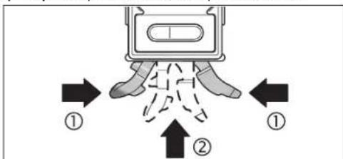
3okpema,peryraepnoTPOUHuaTeTOBEPXHI KANO BHXIHO HO TOBOPYA3epa iCmkyTe TPHOBMy 3a TMIIIO6 He SAAHIIACO BOPCHIK.
KJIO He3BAAIOH NapeIbHy npOeApy BHIOTOBaHHI bHIIPObHaHHI BMIPIOBAHn PnPAHCE-TAKH BNIAE 3AADy, pEMOH MT MaE BIKOHyBaHn AMIE MAICTepHNA, ABTOINIOHA DA EAEKTOPIHCTpymETT BOSch. He BIXpAHBaNT CaMOCTIHHO BMIPIOBAHn IHCTpMHT.
TnpybA-HKAA3NTHAHHJ 3aMAOBaEHH3aHTaHCH,6yAB AACKa, OoB'HKBOO 3aHaayte10-3aHHHbTObAHNHHOmeP,IO 3HAooADtcbHa 3aBOcDpTaXhUHBMIBPOBALHORo PnnaAdy.
HaCnHaeBmipkoBaHnPiHaaHapeMOHTBaXnCHiCyMI24.
Cepicha MaHCTepHaIO6cAryBOyBaHHKaIeHTIB
B cepchm Mnctephi Bn OPMMAE biuobd Ha Baai 3aunH HCTOBOH pemHTy ITEXHHOTO o6cayroByAHN BAIIO TOPOAkyT. MAOKHN B DETAAR IHOPMauio 0do 3aIactH MOKHA 3HaHn 3a aapeco:
www.bosch-pt.com
KohcybTaHTB Bosch 3 paiaCTIO DOIOMOKyT BAM pni 3aHTAHX CTOCBOH KJIIBAI, 3aTOcYBaHH I HAIARoXeHHIPOyKIIIB I INAAADJDOHNX.
IaPapTHTHe O6cAYOByAHnR I pOMHT EKTKPOHCTPMyETHYAJI CHIOUbIaHO BmOHIrI HOPM BHOTOBAOBaYa HTePpOIT BCIX KPAHl AHHyE IpMOHx AB0 ATOPH3OBAHIN CEPBICHX CEHTPAX fipMn P'oBept BouI. TIOITEPEJKEHH! BHKOpCTAHN KoHTpaKaTHOI npOdykui Hbe3eTneHc EKAYTAaII MOKe MAT HEtARTHH HACAIADKHN AHDAPOBJ. BRTOBMeHHI r PO3NOBtAEKHON KOHTpAdPAKTHIO pOdykui IIpepeCaIAyCTb 3a3akOHOMB aAMHICPTaHBHOMy I KPMHHaHbOMy Nop4Ky.
ykpaiHa
TOB PObepT Bow
CepBichHJIeHTpeAekTpoINCTpyMeHITB
Bya.KpaHn,1,02660,KuB-60
YkpaiaHa
TeA:+38(044)4902407(6aataokaHaBHH)
E-Mail: pt-service.ua@bosch.com
OphiuiHnIcAaT: www.bosch-powertools.com.ua
Apeca PerioHaBnHex rapaHTHnx cpeChnx MaCTepeh 3aHaeha HiaiohaHomy rapaHTHmOy TaOH.
YTHAI3aui
BmipioBaHbI pHaAaH, pHaAaI yIaKOBky Tpe6a 3daBaTH Ha ekOIoIHO HCTy TOBTOPII nepeo6Ky.
He BnKuAnTe BmPiOBAhBii HcTpMyHnTa AkyMnyTopHi 6batae/6bataeKnB noobyToBe cmiT!
AMNEAARKpaIH EC:

BIDIOBIAHO AO EBPONIEcKOI HNPEKTHBN 2002/96/EC Ta
EBPONIEcKOI HNPEKTHBN 2006/66/EC BIDIPAAUoBAHNI
BHMIPOBAHNI PIIaAHI, IIOWQKeHNi BOIAPUcBAHNI
AKMYLATOPHI BATEpi/6aTaePi/6aTaePINOJI3AbaATHCJ
OKPMeI yTNAI3YBaTHNC EKOIOTHQ NCHTmCTOCOBM.
Moxawbi 3minn.


134 Romana
Româna
Instructiuni privind siguranta si protectia muncii

Pentru a putea lucra nepericulos si sigur cu aparatul de maura, trebue s ciiti si sa respectati toate instru tionu. Nu distrugeti niciodata placute de averiztare ale aparatului de maura, facandu de nerecuncosut. PASTRATI IN CONDITI BUNE PREZENTELE INSTRUCTIONUINI.
20 Capac compartment bateril laser
21 Orificiu de lesire radiatie laser
22 Placuta de avertizare laser
23 Numar de series
Conectare/deconnectare laser
Pentru connectarea laserukui apasai tasta pornit-oprit 19 adcund-o in pozita, i.
Nu indreptata raza laser asupra personoelar Sau animalelor si nu priviti direct in raza laser, nici chiar de la distanla mai mare.
Pentru deconectarea laserului apasati tasta pornit-oprit 19 educand-o in pozitia 0^
- Nu lasati aparatul de māsūrā nesupravegheat cu laserul conectat ši deconecta ti laserul dupautilizare. Alte persone ar putea fi orbite de raza laser.
Cand nu fofoisi laserul, deconnectatiI pensru a economisi energie.
Schimbarea unitàti de masura (vezi figura A)
Puteti comuta oricand entre unitàtille de matura, ^c^a ,% ^b si, mm/m . Apasàti in acest scop tasta de schimbare a unitàtiljor de matura 5 de câte ori este nécessar pána cánd pe afisajul f va apàraea unitàtela de matura dòrità.
Valoarea másurata curenta este transformata in mod automat.
Reglajul unitatai de masura se pastreaa si in cazul deconnectarii si reconectarii aparatului de asura.
Onncnne Ha npOkyTn Bb3MOxHOCTHcMy
Mon,OTBopete pa3rBaAata ce CtpaHHua c pHpynHe Ha NAmepbaTeHHHa ypcnH,doKATO CYETe PbKOBOCTBOTo,HOCTABe OTBOpEA.
TpeHa3NaeHHe Ha ypeDa
NMepeaIHHY pEe pEaHaHauH 3A IpeuHsHo NMepeBaHe IpeHaHa He HA KaOHKe.
H3MePbATEAHHTypeeOITINMH3NPAH3aH3IOA3BaHeB3akpTNTOMEJHEHRA.
H306pa3eHH eAeMeHTn
HomeppaheToHa enemehntte ce OTHACoHO6paekhento Ha KEMepBaTeAHNpyedHa cTpaHuaTaCfhyptte.
1 ByToH 3a 3ByKOB CNHnA
2IyckOBIIpcKbCBaH3McpeBaHe Ha HAKAHOH/Anm
3 ByTOH 3a TPOMRHa HA HYAeBaTa TOUKa Alt0
4 ByToH 3a KaAM6pHpaH/yeBaMwBaHa He HA MHepeHata CToHOCCT CAL
5 Byton 3a CMH3A MEHPHTA EADHHIa/HAMAAJIbHe HA3MpeHATA CTIOHOCT 品 ^ 日 % / 月 /m _ 日 ^
6 ByToH 3aBbpxHaHe/KoIpaHe 'Hold/Copy
7 KaTak Ha rHe3aTo 3a 6aTeepnHa Hb6eTaTa
8 ByTOH 3a N3BaXdAHe Ha OTOPHH HnOHT 3a HnBeAHPaHe
9 PerympaBHT Ha ONOPHNAHCT3a HnBeApaHe
10 ByToH 3a npn6hpaHe Ha onOpHm HHTa HnBeAHPaHe
11AnJn
12XopH3oHTaHaA6bEa
13BepTHKaHaHb6e
14MaHHTN
15Boday3aKoHaHa
16 OnopenKpaK
17Onopch mHOT3a HNBCAHpaHC
18The3aMOHTMPaHEKbMCTaTHB1/4"
19 NyckOB IIpeKbCBAa 3a Nasepa
20 Kanak Ha rHe3oTo 3a 6aTeepn Ha a3epa
21OTBop3aHxOaIyIaIepeHb4
22PpeyIpeaTeHa TaBeKa 3a Aa3epHHA b4
23 CepneH Homep
24PepaHaHaHa
25Koan3a3axBaanahe
26CTA
H306p3A9HHTA H3dHrTPTE HN AH3BbBbO1BbO3bACTBO3a 36KCTAOATAIIN
DAMBAHHTAHNPMNCPOCAEBHE Ca BkAIQOHIN OOKOMAEKOTAKa.
EAEMENTH HADCTAe
a TomoounHn CTpeAKN 3a TpapBnHO To3nHnO HpaHe
bN3mepeHaCTOHHoCT
C CHMBOA 3a BKAIOHcEH 3BYKOB CHTHaA
DcMBOA3aN3TOeHNbATEPn
eHnKaTOp 3a TIpOMHeHa HhyeBaTOka
fMephaeHHnua
TexHHueckn daHHN
| LHΦρον NHBENHP GIM 60 L | |
| Каталхен Home | 3601 K76 300 |
| Диапазон Ha Hмерванe | 0-360° (4x90°) |
| TOUHOCT Ha Hмерванe | |
| -0°/90° | ± 0,05° |
| -1°-89° | ± 0,2° |
| РавоTeH DiHаТAZOH Ha Haэра1) | 30 m |
| TOUHOCT Ha HmВeHmPAne Ha Haэра | ± 0,5 mm/m |
| 1)Пг ДИБАЗПОТПANY YCФОВHA (Нар. НеторецТВЕНИССВЕВЕЛ) paObTHHnT DИAPANOТ MOKA De ETo HαMBAK. | |
| 3a DA CHIQUHHTO NAGHCHINH INPANe Ha BαIIHЯ HmEρBATEACH YPCA CλYH NCCHINH NHomCp 23 Na TâBaCkata My. | |
Bosch Power Tools 1618C0062X| (27.8.12)


142|Былар检кn
| Linhpob Hmbeap GIM 60 L | |
| Pazstojnne H3xO4JIH OTbop 3a Laeepnna lbu -doIen pb6 Na K3MepeBateHn ypeA | 24 mm |
| Klcac Aa3ep | 2 |
| TniL a3ep | 635 nm, <1 mW |
| Диаметр Ha Aa3epHn Aby (tpn 25°C), npH6A. - ha p3cTOnHne 5 m | 3,5 mm |
| - ha p3cTOnHne 10 m | 6 mm |
| Paboten Tempepatypen DnHApaoH | -10°C...+50°C |
| Tempepatypen DnHApaoH 3a clXpaHBAHe | -20°C...+70°C |
| OTHOCTEHa BAaXHOCT Ha Bb3dYxa, MaKc. | 90% |
| OTBp 3a MOTHIPaHne KbM CTaHB | 1/4" |
| BaTePHN - ИamepBaHe Ha HAKAOH | 1x9V6LR61 |
| - Pekim Ha paBoTa C aAsep | 2x1,5VLR03 (AAA) |
| Прдьхгел�нoc Ha paBoTa, ппб. | 300 h |
| - ИamepBaHe Ha HAKAOH | |
| - Pekim Ha paBoTa C aAsep | 20 h |
| MaCa cIbIaCNo EPTA-Procedure 01/2003 | 0,9 kg |
| Pazmepn (ДыЖнHa XIIHPOUHn X BvCOUHnHa | 600x27x59mm |
| 11Ппн ВсБАОПЕРINH YIeOCHBn (HnHnHnHnHnHnHnHnHnHnHnHnHnHnHnHnHnHnHnHnHnHnHnHnHnHnHnHnHnHnHnHnHnHnHnHnHnHnHnHnHnHnHnHnHnHnHnHnHnHnH DAHAPAOH MOKe Da e TOMaBk. | |
| 3a EanIOHHTO RaHIOHIOHpAne Ha BaJua NmpeBaTeHn IypeA cyHx nceoiHnHnHnHnHnHnHnHnHnHnHnHnHnHnHnHnHnHnHnHnHnHnHnHnHnHnHnHnHnHnHnHnHnHnHnHnHnHnHnHnHnHnHnHnHnHnHnHnHnHm | |
MOnTnpaHc
Tocbahe/cmha ha 6atehpnte
H3MpeTaHHTyEaHbA OeTAEHHeHnO TApY TKOBKpIra H3MpeBaHTo HA KaHOAn (HbEaTA) NAnCInrTe C3xpaHbAToEhHa BatePn, CTBtEHbA AaeBp-T oDyPA.
PtpnnpbYBa ce 3a paobota cH3MepeBateAHHypeA da ce IIOABat AANKHO manraHO B6atePN.
Ako PpOaXHTeHO BpeMe HMa Da H3POnBateypeA,H3BaKaAaTe
bateprnE orr. Ipi npdojakmteHc bxcpahnahe bateprnE mOrat da npotekat n da c camoparaed.
TocBaHHe/3aMaHa Ha 6aTepeHnTa 3a AnBeLaTa
H3BaTeB HmMATEHOOT 3MEpBeTAAHnHa pKaNa KaH3DoTo 3a
6atePnH7 C KTIAYHr 3A KAeMHTe. PnTO TOB BHHMaBAte TA He NOBpeDte
KabeAeTO 3a KTIAYHr HA Na KaNA. To CHAHN YBpExdHAHn HA KOHTAKTHTE
TObBxOCTH H KaNA HrE3DoTo 3a 8atePnH 7 MoRAT Da IpeN3BnKtA
rpeKINI INH3MePBAAHTo
BKAUOYE BAPERHNA BY KUYAYNA, KATO BHIMAGATE 3A IOAOHPCTTA. BKApatte BAPERNA, KYUNYHA n KANAKA Hn THEAOTa 3A BAPERH N HmEpeBaTeAHN ypeD, KATO BHIMAGATE DA n HepuinMeTete Kaebna.
ПИМ ПБВОТО ВКИОУBAЕ на АБЕАТа CALEС CMHA на GAtePERTA BCHKN EAMEHNT HA NCTAETA CBETBAT 3A PTHK.1 CEFYHDA И с ue yBa 3BYKO CHHAA. ПИ CMHA на CBETPERTA с TEHTPERTBAT BCHN 3AITOMHEN HACPTOHKKI (ФИKHINHA на HAMPEPABE, Мерра EAHNHLIA).
Ako npyeyntpeHNTENHHT CMMBO 3a 6atepHnTa ce TnBB Ha HCTAer, TPOBbA da 3aemeHnTe 6atePHTA.
TOCTABHRe/3aMHa Ha 6aTePmTe 3a La3epa
OTbOpTeKaNaHa HrHe3dOto 3a BatePMn 20 nIOCTabe6 BatePMn. IpiTO Toba HBMaBaeIe 3a IIpRAHbIAHATA Hm IOAHOCT, H3IObpa3eHa HcFHypata OtBTbPeHHaTcPDAHa HrHe3dOto 3a BatePHNs.
AkoIa3epbTIIpeCTaHe Da CbETH,6aTePmHTe TpBbDa b6bAd3aMeHeHH.
YyTBaHn:PipeyIpeIeAHTCMMBO3aBatePIMTe dHaAHCmEHe ce OTHACAoBatePIMTe HaA3epa.
Ppea CmHa 6abeepnHtE HENPEMeHHO 3KAAOeBHTAaepe.AKO Aa3eepb6dBe BKAoHHeBHO, CbueCTByBa OTaCHOCT O3aCAETRBAHe HA HAMPaue Ce HAO3Mo 1uHa.
BnHn 3aennne 6dHOBpemEnHO BcNHNbATEPN 3aIaepa.
HIOA3BaIte 6atePNOT eHHN CbII PON3BOIDNTN H cEHaKb KaauTET.
Pa6otaypeda
Tyskahe Bekcttaaun
Ipea3BaTe N3MePBeAeAHn Pn6Op OT OBAaKHaBaHe M dpeKTHO Tnadahe Ha CbHueBn Abn.
HeK3AarHte H3MEpBATEAHypeHaekTpeMHN Temtepatypn HAM
9eHHTNMePbTPHN PpOHe. He ro octabaihe
IPObAXHEAO BPEMe BAOTOMoHA. IPhr ToaEMN TMepaTPyHn
pa3ANK OCTABAE H3MEpBATEAHHTypeA da CE TMEtEPHPa, pPeHd A fo
BKAIOUHTe. IPhr KcETpeMHN TMepaTPHyn HA ROeMEN TMepATPPHn
pa3ANK TOHOCCTa Ha H3MEpBATEAHNYpeD MOKe d Ce BAOuH.
H36BaHTe CAnH yDAPn H3NpyCkHe Ha H3MePBeAHHypeA. CEAdAHM MeXaHNH b3AeHCTBnB b-pxH M3MePBeAHHypeA, ppeAH aIpObAKe pabota, TpRbBAHa h3BbPHTe npOBepKa 3a ToCHcTa Ha H3MePBeAHe (BHXKt EIPoBepKa Ha ToCHcTA KaNb6pHa He H3MePBeAHHn H3CTpyMETh, CTpaHNu145).
PbApaBHTe pabOHTHE TOBpXHOCTH HA 3MepeBAeAHN ypeA HCHTH I TO pTeAaBaeTte OYdAPn H CAAH MEXAHNN B3AEHCTBN. HAMNHETO HA 33MbPCBAHNI NAM DEOpMAUNITE MOAT DA I PpEh3BKNKAT rpeuHKI INH M3MePABHeo.
TocTabHe/3axBaUaHa Ha 3MePBeAHHype
3aHaHMePBATE HAAN A PNEHACRTE HAKHOHN,MOKETE HE CAMO DA DIOHTAPATE 3AHEPAEAHYPDE KMB NOBPOXHOCTN,APATIOIARATE IN C APYB 3BbMOKHOCTN DA TOCTABITE/3A6BAHETE.
TocTabaHne C mExAHnHHTe elemEnTH 3a HnBeAmpane
(Hnnp.πpHepaBHeTHoA)(BHXTeΦmR.B)
HaHtCHHe HABbIe KpATKoPaiHO OTOHPOTO KpueV 16,3a Ta H3BaHTe HaTHcHBe ByToHA 8,3a Da3BaHTe OTOpHNH UHTO H3A HnBHeMaPe 17.ue3 BpTeHE Na peryApaNnBHT N9 TACrPoTne OTOpHNH uHTO 3a HnBEmPaHE NO BICOnHnA Taka, Ye Aa3epHHRT A4 Ha 6Be yCTIOpeEN HA N3MepeBAHATA IOBbPxHOT, Pecn. B IIOeTo 3a N3MepeHs CTIOHOT b Ha hCmien da CE h3o6pa3ra BaXeAAHnB tBt Ha HAKoHAc.
-3a p607a 6B3 MxHANHHTE BEMENHTA 3A HBNBAMPAH NPHBEPETE OTHOO OTOPHNK PAK 16 NIIHTA 3a HNBENPAH 17 3a IATAT HANTCHET EAO HKNM AYDPYABETAE YAH AO TOTOPHN KAP (O) H CMEATOBA BAKAPNT OINTOPHNK PAK 16 B H3MEPATeAHN YPDA (2), ADKATO YCCTNIE OTETANBO IIPePAKBAHE.3a INHbPAH NIIHTA 3a HNBENPAH 17 IINBAPHTE BYTOHA 10 CTPAHNO.
3axbaaane Kbm CTaTHB:
IOCTABeTPHcBbEHNHTHEANrOBpCEpa7a3a 6bp303AaBaAHae HA CTaTHB26NnBbPxy 06NkHOBeH CTaTHB3a
foTtApAHn.3AaBAHepTE HMEpAEHHypeC bC3AcToIPOPAaHn
BHNT HaOAPATA3a 6bp303AaBaAHae.
3aBkAIO4BaHeHaA3epaHaTHCHETyNcKOBnIpeKbCBAu19doN03HnA
He HacoohBaTe AaeshPnAb Yb Kc XoHa PAnXKBOTHN; He FaeAaTe CpeuY aaeepHnAb yCb, CuIIO HTOARMO p3CTOHHe.
3aK3A0BaHe Ha aaepa HATMCHE Te TcCKOBn PpeKbCBAu 19doTIO3HJ4
He octabre H3MEBPAEAHNHCPTPMET63 HA3OP C BKAIOUH A3eP;CAEAIOABAHEK3KIOYBAHTeA3epa.CbueCTyBa ONACHOFTpynHAA Da 6bTaI3AEENHIOIAt3EPHENB4u.
Korato He IIOA Bate Aaepa, FO H3KMOyBaHTe, 3a da nectMe Eheprn.
CmHaHa MeepHata eAHHMa (BHXTe cHr. A)
MOKTeAaPbEBAOHTe NOBCRNO BpEMe MEKxMy MEPHHte EaHNNuH 2% 3AeATA HATCHETe ByTOHa S HEKOKKoPaTHo, DOKATO B TIOHOf hAHCnAe CToBnH XeAAhata MePA EaHNuHa. TeKyuaTa CTOHOC PcNEHsCAARBA ABTOMATHNo.
TINH3KIOUBAHE HNOBTOPHO BKAIOUBAHe HA 3MepBaTeAHNIA PIP6Op CE 3aIa3BaTOCaeHO HIOI0A3BaHaTa MEpHa eHHNua.
BkAIOUBAHe/H3KIAOVAHe Ha 3ByKObaTa CHRHaAH3aUNH
C6yTOHa3BvKOBA CHTHAM3aUNHA 1MOXCTe DA BkIOUBOB TE NIKKIOBATE 3ByKOBA CHTHA. PIM BkIOUHE 3BvKOBA CHTHA HA DnCTAEN CE TONIBBA CMBOATC
PnH3KMOUBAHe H BKOUBaHe Ha ypea ce 3ana3Ba TocaeHTo H36paHO CbCTOHNHe HA 3BYKOBATA CNHaAHAaIIIN.
H3mepeha cTOnHOCTI TOMOa 3a HAcOuBaHe
PnBcKa PnpMeCTBaHe Ha hMepBaTeHnna Pnpbop HmpeHata CToHocct Ce TpOMeHn. PnPB3Kn PnpMeHHa HnTOXKeHHeHa H npOopa HauKbAahe COTHTaHEto,doKATO H3O6pa3RaBaHaTt HA NCTaER CTHOHCTIpeTaHe DaCe TpOMeHn.
B 3A1BCHM0CT OTOLOXEHNETO HA N3MEPBAETAHNHA INH6OP H3MEPENHATA CTHOHCT H MEHPATA EHNHJCA CE 3IO6p3A8NAT B3aBPTEHN HA 180°. Taka CTHOHCTA MOKE AECHO DA CEOTHEE H BA TABAHNA NOHINH
Upe3TOMOUIHHTCPTEAKN3A T03HIOHOHPaHe aHa HnCTAeR N3MEpBaTeHNHIT PyePOKBABBA KAKBO TPOKA OTPBBA Da BDE HAKOOHE, 3A da B6de AOCTHHAT UeAEINHARAOH. LEEAEHNHAKAOH e: IPII CTAHADPHN K3MEpBAHIN XOPHOHHTAATA, peCIN.BEPTKAATA, BPEKMO COpEy IpiPApTEHO AanaMetEHN HAKAOH IpiI IPOPMEOHb HAYEBA TOKA 3aTHNCaHATA HAYEBA TOKA. Korato 6bDeAOTCHHTI EJAEHNHAKAOH, TOMOIIHHTe CPTEAKN 3a IO3HIOHOHPaHe aH3e3BAT, aIPII BKAQoeha 3ByKOBA cTHAM3ALnCE CyBaIPODaXKKHTCAch 3BYKOB CTHHAN
PekmmHaH3MepBaHe
3aDbpkaeH/tpeHaCnHe Ha 3MepeHa cTOnHOCT (BMXTe D)
C6ytoHaHold/Copy》6MOratda6b4aTynpaBnBAHHDeeFyHKHH:
3AaPkaHE(HbHO)HaN3MepHa CTOHCT,DAPINCAEDTOBA H3MpeBATEAHHTYpeAaBdePneTcEHT(HATpAKoH3MpeBATEAHHTYpeC E B N03HUA, B KOTIO AHCTMEHTEHC MEOKEAaBaeP3eHTe)
-Ппсанге(«Copy»)нзмеретастовс.
ФнкинФHols(3aBpkahe)
HaTHCHETe 6yToHa Hoid/Copy6.TeKyuata HA3MepeHa cToHIOCT b ce 3aDbPKA HAnDcIAeA, BCNHN EMeENTn HAn DcIAeA OCBEN H3MepeHATA CTHOHTO MIRAT.
- 3aДIПЕВКAOЛСТЕ КМФФУHКIMС «COPу», HATHCHETEБYTOHA 3a 3bYKOBa CINHANHSAUIN 1, 3a DA CTAPTRPATE HOBO H3MEpBAHe - 6yToHa cHold/COPY6
Функин «Copy》(Коюпанe):
- BKAQHETE 3BKYOBATA CTHHAA3AUAH; HKTREK EKIOUVAHE/H3KIAOVAHE HA 3BKYOBATA CTHHAA3AUAH, cTPhNA144).
HATCHETHE 6yToHa eHld/Copy6 3.3anametraBe cTeKyuata H3mepeHa CTOHCT. Ipo3BaYauKa BpKaTb 3yKOB CnHAA, CMBONHTe 3a Mepha eHNHua f 3yKOBcCnHAAaunu CmHrtA
IpeHnpehACHeMOxTeAaKoHnPATErp6oHmEpeHcTOnHOCTHaHTCHETeBTOHY43aaYBEAHWHTeTAHMeTeHATAcTOHOCT, CbOTBeTHObyTOHY5a3aHaHAMHTe.
- IOTCABETHE N3MEPBATEAHNHPyEe HA MACTOPO, KbDETOIpePHEACHTHEKAKHOA. KaKTo EIO6pBaEOHa HcHpyrata, TIPo TOBaTOKHUNHTA HN3MEPBATEAHNHPyEe E6E3HAUYEHNE. TOMOHINHTe CPTAEKN3a 10N3HNOHNHPaHe a TOKA3BATTOCKATA, BKOITHO3MEPBATEAHNHTyPe 1TROBAaD6BeHAKOOHEH, 3AAoDCTHHRe TPEHACHHARNAKAOH. PnD OTOCTHa He 3aTAMTeHHINbFbC eYyBa3BYKOBCHIIAH.TOMOHINHTe CPTAEKN3a N3HIOHNHPAHe a N3H3EBAT.
3a 3a cTnPATE HOBO IMePBHe, HATHCHe OTHOBO 6yToHaHd/007
Bbmpapckn 145
TIpomraHa Ha HyeBaTa TouKa
3aIIO-NECHATAIPOBEPKA HAHAKMOH (HAIIp.45") MOWETe 4IIPOMEHRE HAYEBAATAOUKA HAHMEPBAHETO.
HacOeTe K3MepBaTeAHnypeHnP.ypeoTnHpaHeAo pepepeHTe
AetAA TAKa, yeKbAHTa HyaEBA ToKa AaBb 3IOb6paeHa Ka H3MepeHa
CTHOHt (HAP,45.1).HATChTe He ByTOHa 已 0 ^ 日 .3.MpeHepHa
CTHOHc t Bn CHMOBbTa 3a TPOMeHEHa HyaEBA ToKa e3aONBa Ta MHrA.
DOKATO MHRa H3MEpeHATA CTIOHOCT b,MOKETe Da KOPHPnPaTe Ppy60
M3MEpeHHaKHOHn:HATCHNETE 6yTOHa 4,3a Da YBEHNHTe 3aTAMETeHATA
CTIOHOCT, CbOTBtHO 6yTOHa 5,aDa HaMaNHe (HAPr.OT 45,13Ha45,0°).
3CEKYHd CIEI NOCAEDHOTo HATNCANHe 6yTOH N3HCaNAta HAnCINEM
CTIOHOCT CE 3aTAMETRBA KATO HOBA HyaEBA TOKa.
Cle3aIaMTeBaHTo MHaHbOa eYka3ra,ue HyaEnaTotaTOKa e TPOMeHaHa. HaCHMaTeKuTaH3MaHepoCT hoTHocB ce 3HO6p3BaH CnPIMIOAIIaHMeHTA HOBA HyaBE ToKa,cbUO INOMOUHTHE CTPEAN32 TO3HHIOHNHPaHe N3ByKOBaTA CHHaN3aJIiCa OTHOCIEAHN cTIPMO HOBA t HyaBe ToKa. TIPmep: TPH HAKAOt OR 43.8c nPIMO XOpH30HTAATA h PedeBaHrTeHo 3aIaMeTeHa HyaBE ToKa 0145" HA HcImeCe H3o6pa3a1n.2
3a Da ce bBpHete OTHOBo kBm CTAADAPHTA HymeBa TOKA 0°, HATCHETe eHN OT BYOTHOFE AltO 3°. 3.Hold/Copy6 HAM CAL4.CHMBOBt 3a TPMcHbEA HymBaTOKa e HnCBA.
H3mePbAHe/tpenacaneHa hakAoHH 6e3KoHTaKTHO
CTOMOHTA Ha Hasepa MoKeTe Da H3MePBeTae,peCn. Ta npeHAcTe HaKMOH 6e3KOHTAKTHO, CbUo H aToEMMa3CTOHHN.
HE HAOCHIJIAE 3AEEPHNIAbH KmXpOJ HAN XKBJBOTNH;HE FAEAIJIe CpeyI A3EPHNIAbCu,CbIOHOT OTOARMO Pa3CTOHNE.
Korato Mapknpate,OT6eBAHTBHNHcMo cHbpa Ha AaeHPTO HETHO. ToaEMHHATA HAa3EPHTO HETHO CE pOMeHc P a3- CTORAHETO.
3a HmepBaeHn HA KANOH HAcOeTe HmEpBaTeAHHN HhCTpyMeTt Ka,Ye
Aa3epHnHbY Da IpMnHAA YcIOpeHO Hn HmEpBaHaTt ATOBbXHOCT.3a
TpnehaHe Hn HAKAOH HAcOeTe HmEpBaTeAHHN HhCTpyMeTt Ka,Ye
KAAHnHn HAKOH Da B6de H3o6pa3E H TMOTo 3a HmepeHa CTOHOCt B n
CAeaTOBA OToBeAEkete HAKAOH Eblpxu eAebata NOBbPxHOCT C NOMOHTa HA
Aa3epHATA TO4Ka.
YMaTaeH: PII INPEHACHEH H NAKAOHN C TMOOHTA HA A3epa He 3abpaBHe, Ye a3epEHNHTb YPmENHABBA 24 mm HaADoANHnPBb Ha 3MpeBATEAHN HHCPTyMeH.
IpoBepKa Ha ToHocTtHa KaH6pHpAHe Ha H3MePbATEAHNHHCTpymENT
TIpOBepKa HaToHocCTTaHa H3MepBaHe
IpeH KPHTHH N3MEPBHA,CAE TPOAEMTMEPTepaTPH NIPOMEH N CAdyapn IPOBEPBAHTe TOHOCTTA HA 3MEpBATeAHN yPeD.
TpeHn H3MepBaHTo ha bHa <45" npOeBpKaTa TpBbDa ca He 3BbpHn Ha pRaHa, TpNbAM3HTeAHO XOpN3OHATA NaTOBpXoCT, TpeHn H3MEpBaHe Ha bHa >45° -cOTBeTHo HA paBA, Tnp6H3NTeAHO BepTHKAnHa TOBpXoCT. BKIOUeTe H3MePbATEAHn PpHbOp n roTOCTaBeTe Ha xOpN3OHTaHa, peCn. BEPTHKANHa PABHHa.
H6epTe Mepnata eHNHa « (BHXTe CmHa Ha MePnTa eHNHa, cTpaHnA 144).
H3aKaaiTe 10 s n cLd ToBa 3aNiWtepeyAtata OI3MePbaHeto.
3aBbptetHe H3MePBeAeHnHa ypeHa 180c OKoM BoeTnKaHAnoc. H3auKaHte OTHOBO 10 ckyHn OH6eXeBTopTa H3MepeHa cTNOHCT.
KAnbnpaHTe N3MepeBateAHN yPeA cMo aKa p3AAkata MeXy ABTe H3MepeHH CTOnHOCTn eTo-TOAA mOr 0,1°.
HbpuuTc HpHApHTo HPiNbOpa BIO3HnHTA, B KORTo pAAKATA HA
H3MepeHHTe CTHOCHTe H aXbBpaHaa PteaeHo AOYCTMaTA
(BepTRHa Hm XOPH3OHTaHa).
KaAho6DHPaHE cTbPMIOBbPdXOCTHe 3aIOCTABHRe XOpH3OHTAHO (BHxTe pHr.E)
TIOBpXHOCTTA, KOATIO IIEI H3IOA3BaTe 3a KaANbPbAe HA N3MepBaTeHnH 1TIP6Op, he TpBAa Da Ce OTKAOHBba OTOXPBOHTAHATA C TOBHeO 5° AKO OTKAOHCHETo EIO TOARMO, PPOUEcBt HA KANbPbAe CE PPcKcBAH HA DCIAEe CA HO6pBaBA CHMBoA1e
BKMHOCTHMEHMPOATEAHNHPyEDnTONOCTABTEeHAAbPxy XoPHOHTAHA NOBxPBOCTTAaYMeBAeTA12a eOBpHATAHARope HnCTAETT 11aE hACOHNEKBM Bac. MauKaJIre 10 cekyHAn
CMA TOA HATHCHTEA 3nP6h2.5cKeyHb6yToHa3a KaAM6pHpaHE aCAL4,0kato HA HCTAA3Ka kTkoTe cBOAHHaHJNAIC a CAL1. CACA TOBA H3MCPHATA CTNOHOT HA DNTAACIATOBDA DA MHA
3aBbPteE KMEBPeTENHH PnH6Op HA 180° OHOAO BEPNTKHa OC, TAKA HE MHeBaAATA DaNPOBAAxAe OoBpHArAe AACHTMeTT 11Aa ce aBbPn HApTOBNOOAnKHCTa CPhA. NsKaHtTe 10 s.
4 CaeToba HATHCHEOTHOBO 6yTOHa 3aKaHbPnPahe cCAL4.Ha HACIMTAe 3a KaTko CE h3oB3AIBa cCAL2.CaeToBa HA HAcTMeCE h3oPb3HbA H3MepeHAtcOHTOHCT (6eaMaHrA).C ToBa H3MEpATEHNHTYPed e KaHbPnPaH cPTMnO MAHtA CH TNOBpXHOCT.

OBJ BUCH-1628-002.book Page 146 Monday, August 27, 2012 12:22 PM

146|bblapckn
BBeHara CAE TOTA Tp6bAa KaMbpNpATE hMepeTENHpye CTPMAIO pOHTBOIOOXHXATA CHTOBPOXHOCT.3a ceTATA 3abbpTeTRE hMEpeTENHpye OKOAO XOPHNOTAHNAOC TAKA, YAE NHeTaTA12 da e HAcOHEHA HADOxy, A HcTAAENT 11 -KMa BAC. NOCTABETE hMepeTENHpye AERHaA Bpxy XOpHOTAHNA HOBpHXOCT. HsKaaknre 10 cekyHnA.
6 CATo 10a HTHCHTe 3a PnHbA.2 CekyHd BytoHa 3a KaHbPnHae aCAL4,doKATO HA DCINHe 3a KpKTO CE NOBn HADnCa cAL1. CaTo 10a H3MePDHTA CTNOHCT HA DCNTAEN A3oTHoBA DA MHa
3aBpTe H3MePBeAENHnPb6Op Ha 180° OKoAo BepTHKaHaOC, Taka CE MHeEaIa DaPiOaBAAe HaobpaHa HADOy, A DcHMeHT I1Da Ce aBpTpNtPOPiBOAnOoKHaCTpHa. NsKaakte 10 s.
CnTaTOBATHATCHETeOTHOBO6yTOHAcAMbIPPAeCAL4.Ha HnCTTNE3KaKTAHOceNtO6p3AraBCAL2CnTeTOBAHdNTIeCE H3o6pa3RAHmepehataCTNOHTC(6e3A MnHA).CT OBA HmEPBATEHNHTYPcE KAMbPpAHCPMBOBETeCNTOBbPXHOCTH HA KONTOMOKEA6bEIOCTABEHAAOXDH03HTANHO.
YbTbAe: AkoB CTrIHKHe 3 N H3MPEBATEAHHTIPIINBOP He b6de3AbaBpTAH OKAOI hO6bpAeHATAh fHyrrpaTa O, npocceBt KaAa6bpApe H MOKe da a38bpSpu (cAL2>He cE no606pBaBA Ha dCTTMeR).
KaH6PnPaHe cIpHMo IOBbPxHOCTHe 3a H3MePbaHe Ha BepTKaAHN HAKAOHN (BNKTe pHypaF)
TIOBbpxHOCTa, KOITO Ie N3IOA3BATE 3a KaHb6pHpaHE Ha 3MpeBaTHHHN TPb6Op. He TPABa Ce 0TOKHOHBA OTe BPTKHaTa CTOBte 0T 5^ . Ako OTKHOHENHOTo E NO-FAARMO, PTOeOCbTA HA KAObPpAHe CE PTKcBA Hn ABOCTe e H3IObPAHb CHMBoABT a→→
BkIOHcTcHcPbCTHINypeNTOIPOPTeDOBEPTKAHA NOBpXHOCTTAka,yeKbEaTa13AeHarOpe,aAICMnT 11Ae HACoOH KmBaC.Nhakaiae T 10 CekHyAn
CMA TOBA HATCHETE 3A PPIN62.CAKYH M BYTOHA 3A KAAHbPnAH eCAL4,0KATO HA HCTMNE 3A KPAITKO CE NOBH DAHNCAe CAL1. CMA TOBA H3MEPHATA CTOHOT HE HACNTA EATHOBA DA HNHA
3aBPTeHcMEpBeTENPn6OpHa180°OKAOBEPNTKHaOC. TAKAue HbEbaata DaPNOAAxHa eBpHArTaHora aAHCHTMeTT 11Aa TaEBnHpaTPOBBOAoONKaTHa cPraHa. NsauKaIte 10 s.
④ CaeToBa HAtHCHeTe OTHoB 6yTOHa 3a KaHbPnape A CAL4.Ha HcTtAe 3a KpTaKCe H06pa3BA CA2L。CaeToBa HAnCTmEe Ce H06pa3Ba HMaMepeHata CtoHOCT (6ea DA MHa).C ToBa HMaPeTAEHHHType E KaHbPnPnAp CTPHMO EAHTa CHNoBbPxHOCT.
BeHara CLea TOBa TPr6Ba KaKn6bpAte HMepeBtAHypeT CTPMIOPTOBTOXoHARHTa CHTOBpXHOCT3aOToHpaHe.3a eHaTa 3aBbTePTEHMePBATEAHNpyEkoOKO XOPHNHAAOHC O TaKa,ae AHeLaTAt13aE HAcOUeHa HAOyA,aHcTAeR11- KbM BAC..OnpTePe HMePBATEAHNpyEdoBepTHKAHA ToBpXHOCT.3aKaKaIeTe 10CEkHAn
6CAeT0BaTHAHCHETe3aPnHbA.2CEkyHd 6yTOBa3aKaANBpHpaHE CAL4,DAKATO HADHCINEME KATPOE KOENBH NADHNAcCAI1A.CAE T0BA H3MEHPEDA CTOHCKT HAOTAAETAOBA DA MHA
3aBpTe HcMepbATEENH PnHOp Ha 180"OkAo BepTKHaHa OC, TAKA He h6BaTATA Da npOaBxN Ae aDpoBtHa TAHOAOy, AaHCTAEIT 11Aa 3aBpTHn HA pTOBIOANOoKHATA cPbHa. HsKaKaeTI O 5s
CnTaTbHaHTNCHeOTHOBObyOHaCAL4.HaHcHcHc3KaPktcoe H306pa3BaKCAL2.CAeTOBAHaHdHcHcE HeHsOpaarBa HAmepeHATA CTOnHOCT (6ea3Ma).CToBAH3MepeBATEAHHTypeA e KaANb6pHaaN CnPMo ABete CNIOBbPxHOCTN,CKONTOMOKe Da bDe AOJIPOH DA BEPTHKAHH NIOBbPXHOCTN.
YmbTBAH: AkoB CbTnKHe T N H3MepBeaTHAHRT PTH6Op he 6duae 3aBbP TAH OKAOI h3o6paEHaT ha fHyrrpaTa O, npocc8b KaAah6pbahe Ne MOKeA da 3aBpnn (kCAL2) He ce h3o6paBBa HaNCTmEn.
TpaBpKaHe n cepBn3
TodabpxaHne HIOuHCTBaHc
CbxpanhaBnHpehacnIypeaCaMoBBBKMIOeHATA BOKOMTAEKOBAkTAPnepa3HaYHTA.
IIOaBpKaIe H3MepBaTeAHn ypeA BnHArH nCT. He IIOITOBaIE H3MepBAteAHN ypeB BBoAADn APYTH TeyHOCT. H6bPCBaIE 3AmBCPcBAHHTA CMeKA, AKeO HABAAKHe CkPaI. He H3NOABAIE NOHCTBAII TPTePAH Hn PA3TROPTEAE.
TIOUHCTBAItepeoBHOCTeuaHOHOOBpXHOCTHe HA3XoDAHaA3epHHN AHC HBNHIMABaIte Da He OCTaBt BAACHKN.
AkoBbIpeKnIpeN3HOTIOPOIN3BOACTBOHNBHMMATEHOH3NTHTBAHE 3MMEpBeAeHHRTyeAeCtePoeAn.PemOHbT TpRbBa Da6De H3BbPwE H 0TpO3HnPAH cepBN3a EMeKTPoHNCTpyMeHTN Ha BoJ. He ce OITHTBAITE a 0BtApBe I3MePBeAAHryAeYPe
MOAR, KORAto ce 6bBHTaJIeKTHM3TpeACTABTEAITE H BOII C BbPOnCNI KORA TOPOBΨaTE DEE8BBH NACTH, HENPEHMEO TNOOCHaJIe
10-ncpchnKaTALOXH HmepoTaBcKATAHa H3MePbTeAHHpyeA.
IpiHcO6XoAHMOCTOTpeMOHTIpeOCTABRHTe H3MEPBATEAHHypeB YAHTATA 24.
1618C0062X|(27.8.12) Bosch Power Tools

Srpski|147
CepBn3 N KOHcyIaTauHH
CepBn3bIe OTOROBOPH H BUNPOCHTe BNOTHOCHO pEMOHTN HNOAPbKHa 3aKYNTEHINOTBCNPOAUYKT,KAKTIO NOTHOCHO pe3EPBNH qaCTN. MoHTAKHN cpeTKe HNNFOPMaIIa3 ape3EPBNH qACTH MOKTe Aa HAMEPTe CbIIO HA www.bosch-pt.com
EknttO KOHCyTAHn Ha BOU Wue Bn NIOMHe C yDOBOACTBE PIPBbPcOH OTHCHOA3KytYBaHE, PIPAOKHE Hn B3MOXHOCTHa HACPTPOBAHe Ha pAAuHN IPOQyKH OT IPOK3BOACTBeHATA rMa HA BOU HONHTAHENI PIIICIO6OeAHN 3A THX.
Po6epBouE0Oa-6bArapn
BOW CepBn3 UenTbP
TapaHUNOHHH H3BbHrapaHUNOHHH peMOHTN
6yU. UeHnBpbx51-b
FPI Bn3HecueHtp 1407
1907Cofna
Te.:+359(02)9601061
TeA.:+359(02)9601079
ΦaKc: +359(02) 962 5302
www.bosch.bg
Бракуванe
NMepeBATEHNAYpEa,DMbTAHIEAHTHE PnPCNPo6MENHA ONaOKOBKHTe TIPbBA da b6daI IOAOKeHNHa EKOOMHIN HApepaOta Ka yCBOBaBaHe Ha CbAdbKaHJIteCe B T8XcCPOBHNHa.
He 3xBpbIe H3MepBaTeAHypeHn AkyMylatOpHn BatePHN/6aTePMH pHbTOBHeOTnAdbu!
Cama 3a ctpaanOT EC:

BcHaacn EOpntckA AnpeKtnBa 2002/96/EO
H3MePbTaENyepn HcbTaHcO EOpntckAnpeKtnBa
2006/66/OGxkyMylatOPnH OaNkOBHeHN BatePHN, KOHO He MoTAT Da CE H3IOm3BAt ToBeue, TpNbBa Da Ce
CbHpAT OtaAHO H aBdA TIOAarAHN Ha NOXoAAuHa
Ipepaotka 3a OIIIOAOTBopBAHe Na CbApkauHte Ce B
Tnx CyopBNH.
Tpabata 3a K3meneHHMa3a3eHH.
Srpski
Uputstva o sigurnosti

Sva uputstva se moraju citati i pazite na njih, da bi sa ternimn alatom radili bez opasnosti i sigurno. Neka Vam tablice sa upozorenjem na ternom alatu budu uvek citjlive.CUVAJTE OVA UPUTSTVA DOBRO.
Oprez - akso kariste drugi ureddjaji za rad ili povesavanje od onih koji su ovde navedeni, ili izvode drugi postupci,mez ovo voditi eksplozijama sa zaarenjem.
Merni alat se isporucje sa Jednom upozoravajucom tablicom (u prikazu mernog alata oznacena na grafickoj stranici sa brojem 22).

OBJ BUCH-1628-002.book Page 172 Monday, August 27, 2012 12:22 PM


172 | Latviešu
OBJ BUCH-1628-002.book Page 173 Monday, August 27, 2012 12:22 PM
Latviesu 173
23 Serijas numurs
24 Aizsargsoma
25 Noturjosta
26 Stativs
^a Attelotie vaiaprakstitie piederumineietilpststandartaiegades komplekta.
Indikacijas elementi
a Izfdzina'sanas paligindikatori
b Merijuma rezultats
c Tonala signala indicators
Baterijas nolietosanas indicators
e Izmainita nullpunkta indikators
f Mervienibas indicators
Tehniskie parametri
| Digitalais noieces mertijs GIM 60 L | |
| Izstradajuma numurs | 3601 K76 300 |
| Merisanas diapazons | 0-360° (4 x 90°) |
| Merisanas precizitate | |
| -0°/90° | 0,05° |
| -1°-89° | ± 0,2° |
| Lázera darbías tátums1) | 30 m |
| Lázera izfidzinañas precizitate | ± 0,5 mm/m |
| Attalums: lázera stara izvadúka - mérinstrumenta apaksejá mala | 24 mm |
| Lázera klase | 2 |
| Lázera starojums | 635 nm, <1 mW |
| Lázera stara diametris (pie 25 °C) apt. | |
| -5 m attalumà | 3,5 mm |
| -10 m attalumà | 6 mm |
| Darba temperatura | -10 °C...+50 °C |
| Uzglabásnas temperatura | -20 °C...+70 °C |
| Maks. relativais gaisa mitrums | 90 % |
| Vitne stiprinásnai uz stativa | 1/4" |
| Baterijas | |
| -nolieces merti Jam | 1 x 9 V6 L R6 1 |
| -lázeram | 2 x 1,5 V L R0 3 (A A A) |
| Darbías laís, apt. | |
| -nolieces meritajam | 300 st. |
| -lázeram | 20 st. |
| Svars atbilstosi EPTA-Procedure 01/2003 | 0,9 kg |
| Izméri (garums x platums x augstums) | 600 x 27 x 59 mm |
| 1) Nélabevigos darba apstaklos (piemeram, ueños saules staros) darbías talums samazinas. | |
| Méristumenta vienozimigai identifikácji kalpo serejias numurs 23, kas atrodams uz markejama plaksnites. | |
Montaža
Méj—I I 1000000000000000000000000000000000000000000000000000000000000000000000000000
信号音の才n/才
信号音SUSHT子1上,信号音的SUSHT子入扎切了可。信号音的SUSHT子入扎上,DIsPLE上二扎表示之
OBJ BUCH-1628-002.book Page 193 Monday, August 27, 2012 12:22 PM
中文|193
181/4"的三碘呆接头
19激光向起停开关
20针对激光的电池盒需
21激光反射门
22激光器降
23序列号码
24 保护套
25叉撑带
26三脚架
OBJ BUCH-1628-002.book Page 198 Monday, August 27, 2012 12:22 PM

198|中文
中文
安全規章

OBJ BUCH-1628-002.book Page 199 Monday, August 27, 2012 12:22 PM
中交199
OBJ BUCH-1628-002.book Page 205 Monday, August 27, 2012 12:22 PM
1-1205
17
18
19 1
20
21
22
23
24
25
26
王明山月青明月明月明月明月明月明月明月明月明月明月明月明月明月
a
b
c
d
e
f的图
国
aalalalalalalalalalalalalalalalalalalalalal
i 1
y
y
jglai jieiie
24 1
jui jie yiau a2
y
g y aal gaae gaae gaae gaae gaae gaae gaae
www.bosch-pt.com
1
g
y
y
y
a
1
|211
a y a 100000000000000000000000000000000000000000000000000000000000000000000000
45 45
45
45
45
45
45
45
45
45
45
45
45
45
45
45
45
45
45
45
45
45
45
45
45
45
45
45
45
45
45
45
45
45
45
12 12
13 Alt0 13
20 1
y
1 45>45<2
(212 000000000000000000000000000000000000000000000000000000
E 12450000000000000000000000000000000000000000000000000000000000000000000000000000000000000000000000000000 ①
CAL1:calal y 11244 CAL4 calal y 112444 CAL4 calal y 112444 CAL4 calal y 112444 CAL4 calal y 112444 CAL4 calal y 112444 CAL4 calal y 112444 CAL4 calal y 112444 CAL4 calal y 112444 CAL4 calal y 112444 CAL5 calal y 112444 CAL5 calal y 112444 CAL5 calal y 112444 CAL5 calal y 112444 CAL5 calal y 112444 CAL5 calal y 112444 CAL5 calal y 112444 CAL5 calal y 112444 CAL5 calal y
Bosch Power Tools 1618C0062X| (27.8.12)
212|
(c)j()
15p25
y 1
p 1
- uddiy 10
1
Jy
S = 10,
100
y
yJyJy
19, 10
paaa aee
yjj
0j19laby j
1
y
(A,)
1
y
1
y

y
1 1
4y
y
aagllgaoaiy
sS 1
y
y
100
y
1
Copy 1234567890123456789012345678901234567890123456789012345678901234567890123456789012345678901234567890123456789
y
y
(Djgl)
6Hold/Copy 1
()
Dopy)
Hold
6 Hold/Copy
y
iL1111111111111111111111111111
.6 Hold/Copy jh kai
Copy
(212i,yjgaiyjyjyjyjyjyjyjyj
6.Hold/Copy
c 1
a 1
5 4
4.4.2.1

|213
1 1 1 1 1 1 1 1 1 1 1 1 1 1 1 1 1 1 1 1 1 1 1 1 1 1 1 1 1 1 1 1 1 1 1 1 1 1 1 1 1 1 1
j2jN 1
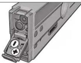
20 20
1000000000000000000000000000000000000000000000000000000000
#
f( x) 定义域为 x x k t_2t_2 ,其中
y
J 1111111111111111111111111111111111
1 1
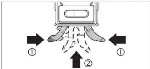
17 16 16 16 16 16 16 16 16 16 16 16 16 16 16 16 16 16 16 16 16 16 16 16 16 16 16 16 16 16 16 16 16 16 16
1
18 24 25
yblll 1
14 15
16
Bosch Power Tools 1618C0062X| (27.8.12)
214
14
15
16
17
1/4 18
19
20
21
22
23
24
25
26
y
ziliulol
a
b
1
d
e
1
2.1.1.1
| GIM60L | |
| 3601 K76 300 | ### |
| 0-360°(4x90°) | ### |
| ±0.05° | ### |
| ±0.2° | 89°-1° |
| 30 | (1 ###) ### |
| 0.5± | ### |
| 24 | ### |
| 635 | ### |
| 3.5 | 25### |
| 6 | ### |
| -10°C...+50°C | ### |
| -20°C...+70°C | ### |
| 90% | ### |
| 1/4" | ### |
| BLR61 ###9x1 | ### |
| (AAA) LR03 ###1.5x2 | ### |
| ###0.9 | EPTA-Procedure 01/2003### |
| 59x27x600 | (###) x (###) x (###) |
J 1
y
y
y
y
4yj 1
y111
y
100
1618C0062X|(27.8.12) Bosch Power Tools
215

| x^ | = 1| x|

y 1
3jai jla la sip glln bao jy 10000000000000000000000000000000000000000000000000000000000000
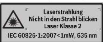
y 100000000000000000000000000000000000000000000000000000000000
y 1
y 1
J 1

aegy 14 y
15
1
aaii
y
1
/2 2
AL03
CAL4
-Hold/Copy 6
7
8
9
10
11
12
13


216|
CAL14 CAL 2L 6
180°,g,g ⑦
aLs-CAL2=Jue 4.CALpao 8
Jg 10000000000000000000000000000000000000000000000000000000000000
y
0e-wwjzg 2
aaii 1
a0000000000000000000000000000000000000
aagcogc caiylo yIyIgJyJyJyJy
a a a a a a a a a a a a a a a a a a a a a
4-CAL-6-Hold/Copy-3Alt0°
gui gao eai
y
L 1
1
auiu g uaiy iuiu ygauu
jaoaLoljgaiiaei jgiayao
aai oai iai gaii gaii gaii j jai bai j s aia
S 1
a101 1
j, g, g, 1, g, g, g, j, j, j, j, j, j, j, j, j, j, j, j, j, j, j, j, j, j, j, j, j, j, j, j, j, j, j, j, j, j, j, j, j, j, j, j, j, j, j, j, j, j, j, j, j, j, j, j, j, j,
aas 1 j g aol s l bajl jagc a o
a 1
j222 24 j1 j1 a1wg2 g 1j1i p1e0a5 a
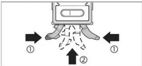
17 16 16 16 16 16 16 16 16 16 16 16 16 16 16 16 16 16 16 16 16 16 16 16 16 16 16 16 16 16 16 16 16 16 16
181/4" aL 20000000000000000000000000000000000000000000000
14 15 16
C y 25 aaiy gao 15 400000000000000000000000000000000000000000000000000000000000000000000000000000
25 aagge gaae jyjgagge
j 2 j 2 j 2 j 2 j 2 j 2 j 2 j 2 j 2 j 2 j 2 j 2 j 2 j 2 j 2 j 2 j 2 j 2 j 2 j 2 j 2 j 2 j 2 j 2 j 2 j 2 j 2 j 2 j 2 j 2 j 2 j 2 j 2 j 2 j
125 100000000000000000000000000000000000000000000000000000000000
A yag aegg ggeaagaaagaaagaaagaaagaaagaaagaaagaaagaaagaaagaaagaaagaaagaaagaaagaaagaaagaaagaaagaaagaaagaaagaaagaaagaaagaaagaaagaaagaaagaaagaaagaaagaaagaaagaaagaaagaaagaaagaaagaaagaaagaaagaaagaaagaaagaaagaaagaa
J 1 1 1 1 1 1 1 1 1 1 1 1 1 1 1 1 1 1 1
jglgaiy gaiy jiai yj 100
220|
yjj jyj jyj jyj
a a 0j12g j1+
y 1
jL11 j=0 g11g11g11g11g11g11g11
(alkali-manganese)
15gjL 2
oaii 10000000000000000000000000000000000000000000
y
55
1 1
217g0sfojol;Joaohgoleo, Jisso
g a yy jy jy jy g jy d e jy y y y y y y y y y
yj 10
.
yj0j1j1j2j3j4j5
g 1
1
()
Bg#
17jL8,80s,Ls
as 15 15
g aag g Lai j 0 0 0 0 0 0 0 0 0 0 0 0 0 0 0 0 0 0 0 0 0 0 0 0 0 0 0 0 0 0 0 0 0 0 0 0 0 0 0 0 0 0
y 14 (golj) gil c a y jay
jie jie jie jie jie jie jie jie jie jie jie jie jie jie jie jie jie jie jie

gagaaagaaagaaagaaagaaagaaagaaagaaagaaagaaagaaagaaagaaagaaagaaagaaagaaagaaagaaagaaagaaagaaagaaagaaagaaagaaagaaagaaagaaagaaagaaagaaagaaagaaagaaagaaagaaagaaagaaagaaagaaagaaagaaagaaagaaagaaagaaagaaagaaagaaagaaa

sLACgOg:Wz
y 1
ole:wojololalow
a a a a a a a a a a a a a a a a a a a a a a a a a a a
olw
aai jai ay aagaa aaaalaae gaaas aol alaae
()
2
AIt 0" joo aos
CAL. 4
- GIM 60 L Professional
- BOSCH
- English|13
- | English
- Product Description and Specifications
- Intended Use
- Product Features
- Display Elements
- Assembly
- Inserting/Replacing the Battery
- Inserting/Replacing the Battery for Grade Measurement
- Inserting/Replacing the Batteries for the Laser
- Switching the Laser On and Off
- Changing the Unit of Measure (see figure A)
- Switching the Audio Signal On/Off
- Measured-value Indication and Alignment Aides
- Measuring Functions
- Holding/Copying a Measured Value (see figure D)
- Changing the Zero Point
- | English
- Contact-free Measuring/Transferring of Grades
- Accuracy Check and Calibration of the Measuring Tool
- Checking the Measuring Accuracy
- Calibration for Horizontal Surfaces (see figure E)
- English|19
- Calibration for Vertical Surfaces (see figure F)
- Maintenance and Service
- Maintenance and Cleaning
- After-sales Service and Customer Assistance
- Great Britain
- Ireland
- | English
- Australia, New Zealand and Pacific Islands
- Republic of South Africa
- Customer service
- Gauteng - BSC Service Centre
- KZN - BSC Service Centre
- Western Cape - BSC Service Centre
- Bosch Headquarters
- People's Republic of China
- China Mainland
- HK and Macau Special Administrative Regions
- Indonesia
- Philippines
- English|21
- Malaysia
- Thailand
- Singapore
- Vietnam
- Disposal
- Only for EC countries:
- Bortskaffelse
- Avfallschantering
- Suomi
- Tonoetnon/AAayi nncnparapuc yia to Aieep
- EAnvka
- Aetroupyia
- Oean aeLcToupyia
- Tomoetnon/Tepeon Tou epyaleiou peronoc
- Σερεωηστο τριπόδο:
- Lepewon pe paayvnt:
- Tepeowneuavrcotepeoos(βaeneikovcC)
- EMnyk@83
- EvepyonoinAmevpeyoonoinouieep
- AALLAY movadac metponc (Bleme ekova A)
- EvpeynoinAnAevepyooninTouakouotkoohpatoc
- EvEeEgTnuepeToonncKaIBoOnmuTaEuBuypuPmionc
- | Türkçe
- 100|Cesky
- Yka3aHHIto6e30nacHOCTH
- 120|Pycckn
- OttcaHne IpoAkyTa n yCAYr
- TIPMHENHNE TO Ha3haeHHIO
- H306paXeHHbIe coCTaBbIe yactn
- AeMeHTbHnHnKaun
- BcTaBA/3aMeHa6aTaapeekAAnAa3epa
- 122|Pycckn
- Pa6ota c HNCTpyMeHToM
- 3KcTAYataaH
- YcTaHOBka/3aKpeTAAEHeH 3MePeHTeAbHoTo HmCTpyMeHTa
- 3aKpETaHHe Ha WtTaTHBe:
- 3aKpeTaeHHe TpH TomoUH MarHTOB;
- 3aKepeTAAHHe TpN TomOuIN KpTeKExhBIX pemHRe (CM.puc.C):
- BkaKouHHe/BykAIOUeHHe H3MepeHHy rHa KaHOHa HAcCTaEer
- BkaioyeHMe/BbikaioyeHMeAa3epa
- Cmeha eHnhi H3mepeHH (cm.pnc.A)
- BkIOUeHHe/BbIXIOUeHHe 3ByKOBOrO crHaHa
- OTo6paXeHHe N3MepeHHoro 3HaueHn HBCtOMorateAbhble Wtpnx DA BbBepK
- Pexnmbi h3MepeHH
- ΦHKCNPOBAHNE/πepeHOCn3MepeHHOro 3aueHHa (cm.phc.D)
- DyHKUHa aHolda
- ΦyHKmR eCopy:
- KaAn6pOBA BeptNkAAbHbIX ToBepXHOCTn pMaerHaHr (CM.pHC.F)
- Tex06caayxmbaHne H cepBnC
- Texo6cayXHBAHHnOuHCTka
- YkpaHcbKa
- Bka3iBkn 3Texhikn6e3neKn
- Onnc npoaykty i nocayr
- Tpiu3haeHHH
- 3o6paXeHi KOMTOHeHTH
- 128|ykaipcahcbka
- Eaementi hankau
- Texhiuhi dahi
- BCTaBAeHHHa/3aMHa 6aTapeHOK
- BCTPOMAHHa3amHa6ataeIaA BmipobAHnKytIB HaxnAY
- BCTPOMAHHH/3aMHa6aTapeHOKAA3epa
- Ekctnyatauia
- Touatokpo60Tu
- BCTAHOBAAHHA/3akpiIaAeHHBAHMIpIOBaIbHOI pHaAaDy
- BCTAHOBAAEHH3A DTONOMORIO HIBEAIOBAIbHOI MEXAHIKN
- 3MHa HyaoboBOI TOOKH
- 6e3KoHTaKTHe BmipIOBAAH/pepeHeCEHH KytIB HAXMAY
- 132|YkpaiHcbka
- TepeBipKa TouHOcti BHMipOBaHb i KaI6pyBaHHB HBMIPOBaHOrO pHaAaY
- Tepebipka ToHocti BmipkoBanh
- KaI6pyBaHHa roh3oHTaBbHIOBepxhi (AHB, MaA, E)
- Texhihe 06cayrobybaHHIOuHnueHH
- Cepicha MaHCTepHaIO6cAryBOyBaHHKaIeHTIB
- www.bosch-pt.com
- ykpaiHa
- TOB PObepT Bow
- YTHAI3aui
- AMNEAARKpaIH EC:
- Româna
- Instructiuni privind siguranta si protectia muncii
- Conectare/deconnectare laser
- Schimbarea unitàti de masura (vezi figura A)
- Onncnne Ha npOkyTn Bb3MOxHOCTHcMy
- TpeHa3NaeHHe Ha ypeDa
- H306pa3eHH eAeMeHTn
- EAEMENTH HADCTAe
- TexHHueckn daHHN
- MOnTnpaHc
- Tocbahe/cmha ha 6atehpnte
- TocBaHHe/3aMaHa Ha 6aTepeHnTa 3a AnBeLaTa
- TOCTABHRe/3aMHa Ha 6aTePmTe 3a La3epa
- Pa6otaypeda
- Tyskahe Bekcttaaun
- TocTabHe/3axBaUaHa Ha 3MePBeAHHype
- TocTabaHne C mExAHnHHTe elemEnTH 3a HnBeAmpane
- 3axbaaane Kbm CTaTHB:
- CmHaHa MeepHata eAHHMa (BHXTe cHr. A)
- BkAIOUBAHe/H3KIAOVAHe Ha 3ByKObaTa CHRHaAH3aUNH
- H3mepeha cTOnHOCTI TOMOa 3a HAcOuBaHe
- PekmmHaH3MepBaHe
- 3aDbpkaeH/tpeHaCnHe Ha 3MepeHa cTOnHOCT (BMXTe D)
- Bbmpapckn 145
- TIpomraHa Ha HyeBaTa TouKa
- H3mePbAHe/tpenacaneHa hakAoHH 6e3KoHTaKTHO
- IpoBepKa Ha ToHocTtHa KaH6pHpAHe Ha H3MePbATEAHNHHCTpymENT
- TIpOBepKa HaToHocCTTaHa H3MepBaHe
- KaAho6DHPaHE cTbPMIOBbPdXOCTHe 3aIOCTABHRe XOpH3OHTAHO (BHxTe pHr.E)
- 146|bblapckn
- KaH6PnPaHe cIpHMo IOBbPxHOCTHe 3a H3MePbaHe Ha BepTKaAHN HAKAOHN (BNKTe pHypaF)
- TpaBpKaHe n cepBn3
- TodabpxaHne HIOuHCTBaHc
- CepBn3 N KOHcyIaTauHH
- Po6epBouE0Oa-6bArapn
- Бракуванe
- Cama 3a ctpaanOT EC:
- Srpski
- Uputstva o sigurnosti
- | Latviešu
- Indikacijas elementi
- Tehniskie parametri
- Montaža
- 信号音の才n/才
- 198|中文
- 中文
- 安全規章
- 中交199
- 212|
- |213
- #
- f( x) 定义域为 x x k t_2t_2 ,其中
- 1
- yblll 1
- | x^ | = 1| x|
- 15
- 216|
- y
- 0e-wwjzg 2
Brand : BOSCH
Model : GIM 60L
Category : Electronic spirit level