
GLM 120 C Professional - Rangefinder BOSCH - Free user manual and instructions
Find the device manual for free GLM 120 C Professional BOSCH in PDF.
| Product Type | Digital Laser Rangefinder |
| Brand | Bosch |
| Model | GLM 120 C Professional |
| Dimensions (L x W x H) | 142 (176) x 64 x 28 mm |
| Weight (according to EPTA 01:2014) | 0.21 kg |
| Power supply | Lithium-ion battery 3.6 V / 3120 mAh |
| Typical range | 0.08–120 m |
| Typical measuring accuracy | ± 1.5 mm |
| Minimum display value | 0.5 mm |
| Laser class | 2 (650 nm, <1 mW) |
| Inclination measurement | 0°–360° (4x90°) / precision ±0.2° |
| Measuring functions | Length, area, volume, indirect measurement, marking, electronic level |
| Built-in camera | Yes, with viewfinder and zoom |
| Display | Color, backlit, adjustable |
| Data transmission | Bluetooth® 4.2 Low Energy, Micro-USB 2.0 |
| Internal memory | Up to 50 values with photos |
| Operating temperature | -10 °C to +45 °C (max +40 °C continuously) |
| Protection rating | IP54 (dust and water splashes) |
| Charger included | Yes, charging time approx. 5.5 h |
| Tripod thread | 1/4" |
| Cleaning | Soft, damp cloth, no solvents |
| Safety instructions | Do not look into the laser beam, avoid explosive atmospheres |
| Spare parts and repairability | Bosch after-sales service, original parts |
Frequently Asked Questions - GLM 120 C Professional BOSCH
User questions about GLM 120 C Professional BOSCH
0 question about this device. Answer the ones you know or ask your own.
Ask a new question about this device
Download the instructions for your Rangefinder in PDF format for free! Find your manual GLM 120 C Professional - BOSCH and take your electronic device back in hand. On this page are published all the documents necessary for the use of your device. GLM 120 C Professional by BOSCH.
USER MANUAL GLM 120 C Professional BOSCH
natural_image
Illustration of a Bosch POS terminal device with control buttons and display screen (no text or symbols on main body)GLM 120 C Professional

BOSCH
English ...... page 22
Français......Page 34
D
6
E
F

H
2607001391
1 608 M00 05B
BT 150
0 601 096 B00
Deutsch
Sicherheitshinweise


All instructions must be read and observed in order for the measuring tool to function safely. The safeguards integrated into the
measuring tool may be compromised if the measuring tool is not used in accordance with these instructions. Never make warning signs on the measuring tool unrecognisable. SAVE THESE INSTRUCTIONS FOR FUTURE REFERENCE AND INCLUDE THEM WITH THE MEASURING TOOL WHEN TRANSFERRING IT TO A THIRD PARTY.
▶ Warning! If operating or adjustment devices other than those specified here are used or other procedures are carried out, this can lead to dangerous exposure to radiation.
The measuring tool is delivered with a warning label (marked in the illustration of the measuring tool on the graphics page with number (14)).
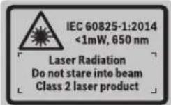
▶ If the text on the warning label is not in your native language, cover it with the label supplied, which is in your language, before initial commissioning.

Do not direct the laser beam at persons or animals and do not look directly into the laser beam or at its reflection. Doing so could lead to blindness, or could cause acci-
dents or damage to the eyes.
▶ If laser radiation hits your eye, you must close your eyes and immediately turn your head away from the beam.
▶ Do not make any modifications to the laser equipment.
▶ Do not use the laser goggles as protective goggles. The laser goggles make the laser beam easier to see; they do not protect you against laser radiation.
▶ Do not use the laser goggles as sunglasses or while driving. The laser goggles do not provide full UV protection and impair your ability to see colours.
▶ Have the measuring tool serviced only by a qualified specialist using only original replacement parts. This will ensure that the safety of the measuring tool is maintained.
▶ Do not let children use the laser measuring tool unsupervised. They could accidentally dazzle someone.
▶ Do not use the measuring tool in explosive atmospheres which contain flammable liquids, gases or dust. Sparks may be produced inside the measuring tool, which can ignite dust or fumes.
▶ Do not operate the measuring tool with the USB cable connected.
▶ Do not use the measuring tool as external USB storage.
Do not use the measuring tool to photograph any people or animals, as this can involve the laser beam being continuously switched on. You could blind somebody or cause accidents or eye damage with the laser beam switched on.
▶ Do not use the measuring tool if the display glass is visibly damaged (e.g. cracks in the surface, etc.). This poses a risk of injury.
▶ Caution! Using the measuring tool with Bluetooth® can cause faults to occur in other devices and systems, aeroplanes and medical devices (e.g. pacemakers, hearing aids). Also, damage to people and animals in the immediate vicinity cannot be completely excluded. Do not use the measuring tool with Bluetooth® in the vicinity of medical devices, petrol stations, chemical plants, areas with a potentially explosive atmosphere and in blasting areas. Do not use the measuring tool with Bluetooth® on aeroplanes. Avoid using the product near your body for extended periods.
The Bluetooth ^® word mark and logos are registered trademarks owned by Bluetooth SIG, Inc. and any use of such marks by Robert Bosch Power Tools GmbH is under license.
Safety instructions for chargers
This charger is not intended for use by children or persons with physical, sensory or mental limitations or a lack of experience or knowledge. This charger can be used by children aged 8 or older and by persons who have physical, sensory or mental limitations or a lack of experience or knowledge if a person responsible for their safety supervises them or has instructed them in the safe operation of the charger and they under-
stand the associated dangers. Otherwise, there is a risk of operating errors and injuries.
▶ Supervise children during use, cleaning and maintenance. This will ensure that children do not play with the charger.

Do not expose the charger to rain or wet condi-
tions. Water entering a power tool will increase the risk of electric shock.
▶ Charge the measuring tool only with the supplied charger.
▶ Keep the charger clean. Dirt poses a risk of electric shock.
▶ Always check the charger, cable and plug before use. Stop using the charger if you discover any damage. Do not open the charger yourself, and have it repaired only by a qualified specialist using only original replacement parts. Damaged chargers, cables and plugs increase the risk of electric shock.
▶ Do not operate the charger on an easily ignited surface (e.g. paper, textiles, etc.) or in a flammable environment. There is a risk of fire due to the charger heating up during operation.
In case of damage and improper use of the battery, vapours may also be emitted. Ensure the area is well-ventilated and seek medical attention should you experience any adverse effects. The vapours may irritate the respiratory system.
Product Description and Specifications
Please unfold the fold-out page with the diagram of the measuring tool and leave it open while reading the instruction manual.
Intended Use
The measuring tool is intended for measuring distances, lengths, heights, clearances and inclines, and for calculating areas and volumes.
The measurement results can be transferred to other devices via Bluetooth® and USB port.
The measuring tool is suitable for indoor and outdoor use.
Product features
The numbering of the product features shown refers to the illustration of the measuring tool on the graphic page.
(1) Display
(2) Measuring button [▲(can be used at the front or side)
24 | English
(3) Soft key [ ]
(4) Plus button [+] / Select to the right
(5) Zoom button
(7) Measuring pin release button
(8) Measuring pin
(9) On/off/delete button [Φ]
(10) Camera button
(11) Minus button [-] / Select to the left
(12) Soft key [ ]
(13) Function button [Func]
(14) Laser warning label
(15) Serial number
(16) Micro USB port
(17) 1/4" tripod socket
(18) Laser beam output
(19) Camera
(20) Reception lens
(21) Carrying strap
(22) Micro USB cable
(23) Charger ^4
(24) Protective bag
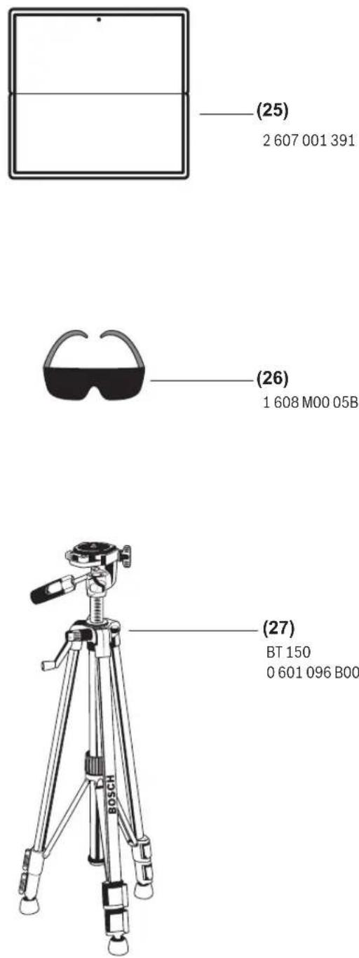
(25) Laser target plate ^A1
(26) Laser viewing glasses ^4
(27) Tripod ^A
A) Accessories shown or described are not included with the product as standard. You can find the complete selection of accessories in our accessories range.
Display elements
(a) Result line
(b) Target display (crosshairs)
(c) Display tilt angle
(d) Date/time
(e) Reference level of measurement
(f) Connection status

Bluetooth ^® not activated

Bluetooth ^® activated, connection established
(g) Battery charge indicator
(h) Measured value lines
(i) Settings (soft key)
(j) Selected measuring function
(k) Internal memory (soft key)
(I) Integrated help function (soft key)
(m) Back (soft key)
(n) Start screen (soft key)
(o) Tool settings
Technical data
| Digital laser measure GLM 120 C | |
| Article number | 3 601 K72 F.. |
| Measuring range (typical) 0.08–120 m | A) |
| Measuring range (typical, unfavourable conditions) | 0.08–60 m^B) |
| Measuring accuracy (typical) | ±1.5 mm^A) |
| Measuring accuracy (typical, unfavourable conditions) | ±3.0 mm^B) |
| Smallest display unit 0.5 mm | |
| Indirect distance measurement and level | |
| Measuring range 0°–360° (4 x 90°) | |
| Grade measurement | |
| Measuring range 0°–360° (4 x 90°) | |
| Measuring accuracy (typical) | ±0.2°C,D,E) |
| Smallest display unit 0.1° | |
| General | |
| Operating temperature –10 °C to +45 °C | F) |
| Storage temperature –20 °C to +70 °C | |
| Permitted charging temperature range | +5 °C to +40 °C |
| Relative air humidity max. 90% | |
| Max. altitude 2000 m | |
| Pollution degree according IEC 61010-1 | 2G) |
| Laser class 2 | |
| Laser type 650 nm, < 1 mW | |
| Laser beam diameter (at 25 °C) approx. | |
| – 10 m distance | 9 mm |
| – 100 m distance | 90 mm |
| Automatic switch-off after approx. | |
| – Laser | 20 s |
| – Measuring tool (without measurement) | 5 min ^1) |
| Weight according to EPTA-Procedure 01:2014 | 0.21 kg |
| Dimensions | 142 (176) x 64 x 28 mm |
| Protection rating | IP 54 (dust and splash-proof) |
| Data transmission | |
| Bluetooth® | Bluetooth®(4.2 Low Energy) ^1) |
| Operating frequency band | 2402–2480 MHz |
| Max. transmission power | 8 mW |
Digital laser measure GLM 120 C
| Micro USB cable USB 2.0 | |
| - Charging voltage 5.0 V | ∞ |
| - Charge current 1000 mA | |
| Battery Li-ion | |
| Rated voltage 3.6 V | |
| Capacity 3120 mAh | |
| Number of battery cells 1 |
Charger
| Article number | 2 609 120 7.. |
| Charging time Approx. 5.5 h | D) |
| Battery charging voltage 5.0 V | = |
| Charge current 1000 mA | |
| Protection class / II | ☐ |
A long battery runtime is achieved by means of energy-saving measures, such as deactivating the Bluetooth® function when not required, reducing the display brightness, etc.
The serial number (15) on the type plate is used to clearly identify your measuring tool.
A) For measurements from the front edge of the measuring tool, this applies for high reflectivity of the target (e.g. a white-painted wall), weak backlighting and 25 °C operating temperature. In addition, a deviation of ±0.05 mm/m must be taken into account.
B) For measurements from the front edge of the measuring tool, this applies for high reflectivity of the target (e.g. a white-painted wall), and strong backlighting. In addition, a deviation of ±0.15 mm/m must be taken into account.
C) After calibration at 0° and 90°. Additional pitch error of max. ±0.01°/degrees up to 45°. The measurement accuracy refers to the three orientations of the inclination measurement calibration, see figure H
D) At an operating temperature of 25 °C. Charging time with 1 A USB charger. Faster charging with the measuring tool switched off.
E) The left-hand side of the measuring tool serves as the reference level for grade measurement.
F) In continuous measurement mode, the max. operating temperature is +40 °C.
G) non-conductive soiling only, whereby occasional temporary conductivity caused by condensation is expected
H) The automatic switch-off time can be adjusted (to two, five, ten minutes or never).
1) When using Bluetooth® Low Energy devices, it may not be possible to establish a connection depending on the model and operating system. Bluetooth® tools must support the GATT profile.
Initial start-up
Charging the battery
▶ Use only the chargers listed in the technical data. Only these chargers are matched to the lithium-ion battery of your measuring tool.
The use of chargers from other manufacturers can lead to defects on the measuring tool; a higher voltage (e.g. 12 V) from a vehicle charger is not suitable for charging this measuring tool. The warranty is rendered void if these instructions are not followed.
▶ Pay attention to the mains voltage. The voltage of the power source must match the voltage specified on the rating plate of the charger.
Note: The battery is supplied partially charged. To ensure full capacity of the battery, completely charge the battery before the first use.
Note: The micro USB port (16) for connecting the micro USB cable (22) is located under the cover of the measuring pin (8). Press the release button (7) to open the cover.
The lithium-ion battery can be charged at any time without reducing its service life. Interrupting the charging process does not damage the battery.
If the lower segment of the battery charge indicator (g) flashes, only a few more measurements can be made. Charge the battery.
If the frame around the segments of the battery charge indicator (g) flashes, no more measurements are possible. The measuring tool can only be used for a short time (e.g. to check entries in the measured value list). Charge the battery.
Connect the measuring tool to the charger (23) using the micro USB cable (22) provided. Plug the charger (23) into the socket. The charging process will begin.
The battery charge indicator (g) indicates the charging progress. The segments flash successively during charging. When all segments of the battery charge indicator (g) are displayed, the battery is fully charged.
If you are not planning to use the power tool again soon, disconnect the charger from the mains.
The battery can also be charged at a USB port. To do so, connect the measuring tool to a USB port using the micro USB cable. In USB mode (charging mode, data transfer), the charging time can be noticeably longer.
The measuring tool cannot be used on its own during the charging process.
Bluetooth® switches itself off during the charging process. Existing connections to other devices are interrupted. Data can be lost in the process.
Recommendations for optimal handling of the battery in the measuring tool
Only charge the measuring tool in the permissible temperature range, (see "Technical data", page 24). As an example, do not leave the measuring tool in a vehicle during the summer.
A significantly reduced operating time after charging indicates that the battery has deteriorated and must be replaced by the Bosch after-sales service.
Follow the instructions on correct disposal.
Operation
Start-Up
▶ Never leave the measuring tool unattended when switched on, and ensure the measuring tool is switched off after use. Others may be dazzled by the laser beam.
26 | English
▶ Protect the measuring tool from moisture and direct sunlight.
▶ Do not expose the measuring tool to any extreme temperatures or variations in temperature. For example, do not leave it in a car for extended periods of time. In case of large variations in temperature, allow the measuring tool to adjust to the ambient temperature before putting it into operation. The precision of the measuring tool may be compromised if exposed to extreme temperatures or variations in temperature.
▶ Avoid substantial knocks to the measuring tool and avoid dropping it. Always carry out an accuracy check before continuing work if the measuring tool has been subjected to severe external influences Accuracy Check of the Measuring Tool.
The measuring tool is equipped with a wireless interface. Local operating restrictions, e.g. in aeroplanes or hospitals, must be observed.
Switching On/Off
During work, ensure that the reception lens (20), the laser beam output (18) and the camera (19) are not closed off or covered, otherwise correct measurement will not be possible.
- To switch on the measuring tool and the laser, briefly press the front or side measuring button (2) [▲]
- To switch on the measuring tool without the laser, briefly press the on/off/delete button (9) [Φ]
▶ Do not direct the laser beam at persons or animals and do not stare into the laser beam yourself (even from a distance).
To switch off the laser, briefly press the on/off/delete button (9) [d].
To switch off the camera, press the camera button (10).
To switch off the measuring tool, press and hold the on/off/delete button (9) [a].
The measured values and device settings in the memory are retained when you switch the measuring tool off.
Camera
Switching on the measuring tool automatically switches on the camera (19). To switch it off, press the camera button (10).
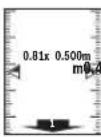
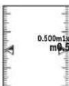
For larger distances (of approx. more than five metres), a target marker is also superimposed to mark the measuring point.
Optimising visibility of the laser point
Especially when using the measuring tool outdoors, in sunlight and also over long distances indoors, the laser point may not be visible. The visibility of the laser point/measurement point can additionally be improved in order to connect the camera by:
- Setting the display brightness (tool settings)
- Using the zoom by pressing the button (5).
Measuring process
Once switched on, the measuring tool is in the length measurement function. For a different measuring function, press the button (13) [Func]. Use the button (4) [+] or the button (11) [-] to select the required (see "Measuring functions", page 28). Activate the measuring function with the button (13) [Func] or with the measuring button (2) [▲].
Once the measuring tool has been switched on, the rear edge of the measuring tool is selected as the reference level for measurement. Changing the reference level (see "Selecting the reference level (see figure A)", page 26). Apply the measuring tool to the point at which you want to start the measurement (e.g. wall).
Note: If the measuring tool has been switched on using the on/off/delete button (9) [∅, briefly press the measuring button (2) [▲to switch the laser on.
To initiate the measurement, briefly press the measuring button (2) [▲] Then the laser beam is switched off. For a further measurement, repeat this process.
With the laser beam continuously switched on and when in the continuous measurement function, the measurement begins the first time you press the measuring button (2) [▲]
▶ Do not direct the laser beam at persons or animals and do not stare into the laser beam yourself (even from a distance).
Note: The measured value typically appears within half a second, and no later than approximately four seconds. The duration of the measurement depends on the distance, the lighting conditions and the reflective properties of the target surface. Upon completion of the measurement, the laser beam is automatically switched off. The continuously switched-on laser beam is not switched off after the measurement (see "Continuous laser beam", page 27).
Selecting the reference level (see figure A)
You can choose between four different reference levels for the measurement:
- The rear edge of the measuring tool (e.g. when placing against walls)
- The tip of the measuring pin (8) folded by 180^ (e.g. when measuring from a corner)
- The front edge of the measuring tool (e.g. when measuring from a table edge)
- The centre of the thread (17) (e.g. for tripod measurements)
The folding out and in of the measuring pin (8) by 180° is detected automatically and the appropriate reference level is suggested. Confirm the setting by pressing the measuring button (2) [▲]
Select the settings for the measuring tool using the soft key (3) [■]. Use the button (4) [+] or the button (11) [-] to select the reference level and confirm this by pressing the button (13) [Func].
The rear edge of the measuring tool is automatically preset as the reference level every time the measuring tool is switched on.
Continuous laser beam
If necessary, you can switch the measuring tool to continuous laser beam operation. To do this, select the settings for the measuring tool using the soft key (3) [ ] Use the button (4) [+] or the button (11) [-] to select the continuous laser beam and confirm this by pressing the button (13) [Func].
▶ Do not direct the laser beam at persons or animals and do not stare into the laser beam yourself (even from a distance).
In this setting, the laser beam remains switched on even between measurements; measurement simply requires one brief press of the measuring button (2) [▲]
The continuous laser beam can be switched off again in the settings or automatically when the measuring tool is switched off.
Settings menu
To enter the settings menu (i), briefly press the soft key (3) [or press and hold the button (13) [Func].
Use the button (4) [+] or the button (11) [-] to select the required setting and confirm this by pressing the button (13) [Func]. Select the required setting.
To exit the settings menu, press the on/off/delete button (9)
[∅ or the soft key (12) [ ]
Settings
| Bluetooth® | |
| Reference level | |
| Timer function | |
| Continuous laser beam | |
| Grade measurement calibration | |
| Target indicator calibration | |
| Internal memory (deleting and formatting) | |
| Tool settings |
Timer function
The timer function is useful when measuring in hard-to-reach areas, for example, or when the measuring tool should be kept stationary during measurement.
Select the timer function in the settings. Select the required time period between triggering the timer and starting measurement and confirm by pressing the measuring button (2) [▲ or the button (13) [Func].
Then press the measuring button (2) [▲to switch on the laser beam and focus on the target. Press the measuring button (2) [▲again to start the measurement. The measurement will begin after the set time period has expired. The measured value is displayed in the result line (a).
The time period between triggering the timer and starting measurement is displayed in the status bar at the top.
Continuous measurement and minimum/maximum measurement are not possible with the timer function enabled.
The timer remains enabled until the measuring tool is switched off or until the timer is switched off in the settings menu.
Tool settings menu
Select the tool settings menu in the settings menu.
Use the button (4) [+] or the button (11) [-] to select the required tool setting and confirm this by pressing the button (13) [Func]. Select the required tool settings.
To exit the tool settings menu (0), press the on/off/delete button (9) [∅ for the soft key (12) [ ].
Tool settings
| Language | |
| Time & date | |
| ft/m | Unit of measurement |
| Unit of measurement for angles | |
| TrackMyTools | |
| i | Tool information |
| Tone signals | |
| Switch-off time | |
| Dimmer | |
| Display brightness | |
| Display orientation |
Setting the language
Select the language option in the tool settings menu. Set the required language and confirm this by pressing the button (13) [Func].
Setting the date and time
Select the time & date option in the tool settings menu. Set the date and time according to the instructions on the display and confirm these by pressing the soft key (12) [ ]
Changing the unit of measurement
Select the unit of measurement option in the tool settings menu. The default unit of measurement is m (metres).
Set the required unit of measurement and confirm this by pressing the button (13) [Func].
To exit the menu item, press the on/off/delete button (9) [⑥] or the soft key (3) [The selected tool settings remain saved after you switch off the measuring tool.
Changing the unit of measurement of an angle
Select the option for setting the unit of measurement for angles in the tool settings menu. The default unit of measurement for an angle is ° (degrees).
Set the required unit of measurement for angles and confirm this by pressing the button (13) [Func].
28 | English
To exit the menu item, press the on/off/delete button (9) [①] or the soft key (3) []. The selected tool settings remain saved after you switch off the measuring tool.
TrackMyTools
Select the TrackMyTools option in the tool settings menu. Confirm the setting by pressing the button (13) [Func]. Initial activation is required. Data can only be transmitted using a suitable app or computer program. TrackMyTools can be deactivated again at any time.
Display illumination
Select the dimmer option in the tool settings menu. The display illumination is continuously switched on. If you do not press any buttons, the display lighting is dimmed after approximately 30 seconds to preserve the battery. The time until dimming starts can be adjusted (tool settings). The brightness of the display can be adjusted to the surrounding conditions in multiple increments (tool settings).
Measuring functions
Note: Integrated help function
Help in the form of an animation is saved in the measuring tool for each measuring function. To access this, select the button (13) [Func], the button (4) [+] or button (11) [-] and then the soft key (3) []. The animation shows you the detailed procedure for the selected measuring function. The animation can be stopped and started again at any time using the soft key (3) []. You can scroll forwards and backwards using the button (4) [+] and button (11) [-].
Measuring length
Select the length measurement mode. To switch on the laser beam, briefly press the measuring button (2) [▲] To measure, briefly press the measuring button (2) [▲]. The measured value will be shown at the bottom of the display.
Repeat the above-mentioned steps for each subsequent measurement. The last measured value is at the bottom of the display, the penultimate measured value is above it, and so on.
Continuous measurement
In continuous measurement mode, the measuring tool can be moved relative to the target, during which the measured value will be updated every half a second. You can, for example, move a desired distance away from a wall while reading off the current distance at all times. Select the continuous measurement mode: To switch on the laser beam, briefly press the measuring button (2)
Move the measuring tool until the required distance value is shown in the display below.
Briefly pressing the measuring button (2) [▲] will interrupt the continuous measurement. The current measured value will be shown at the bottom of the display. The maximum and minimum measured value appear above it. Pressing the measuring button (2) [▲] once
more will start the continuous measurement again. Continuous measurement automatically switches off after five minutes.
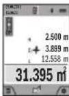
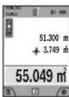
Area measurement
Select the area measurement mode □ Then measure the width and length and height one after the other as with a length measurement. The laser beam remains switched on between the two measurements. The distance to be measured flashes in the indicator for area measurement (see indicator element (j)).
The first measured value is shown at the top of the display. After the second measurement has been completed, the area will be automatically calculated and displayed. The end result is shown at the bottom of the display, while the individual cues are shown above it.
Volume measurement
Select the volume measurement mode □ Then measure the width, length and depth one after the other as with a length measurement. The laser beam remains switched on between the three measurements. The distance to be measured flashes in the indicator for volume measurement (see display element (j)). The first measured value is shown at the top of the display. After the third measurement has been completed, the volume will be automatically calculated and displayed. The end result is shown at the bottom of the display, while the individual measured values are shown above it.
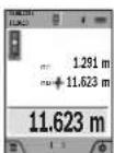
Indirect distance measurement
Select the indirect distance measurement mode. There are four measuring functions available for the indirect distance measurement, each of which is capable of determining different distances. The indirect distance measurement is used to determine distances that cannot be measured directly, due to an obstacle that would impede the path beam or the absence of a target surface that could serve as a reflector. This measuring procedure can only be employed vertically. Any horizontal deviation will lead to measurement errors. Note: Indirect distance measurement is always less accurate than direct distance measurement. For application-related reasons, measuring errors can be greater than with direct distance measurement. To improve the accuracy of measurement, we recommend the use of a tripod (accessory). The laser beam remains switched on between the individual measurements
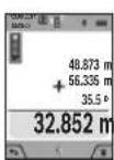
a) Indirect height measurement (see figure B)
Select the indirect height measurement mode
Ensure that the measuring tool is at the same height as the lower measuring point. Then tilt the measuring tool around the reference level and measure distance 1 as for a length measurement (displayed as a red line).
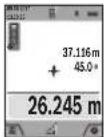
Once the measurement is complete, the result for the required distance X is displayed in the result line (a). The measured values for distance 1 and angle α can be found in the measured value lines (h).
b) Double indirect height measurement (see figure C)
The measuring tool can indirectly measure all distances that lie in the vertical level of the measuring tool. Select the double indirect height measurement mode. Measure distances 1 and 2 in succession as for a length measurement.
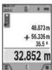
Once the measurement is complete, the result for the required distance X is displayed in the result line (a). The measured values for distances 1 and 2 and angle α can be found in the measured value lines (h).
Ensure that the reference level for the measurement (e.g. the rear edge of the measuring tool) remains in exactly the same place for all the individual measurements in a single measuring process.
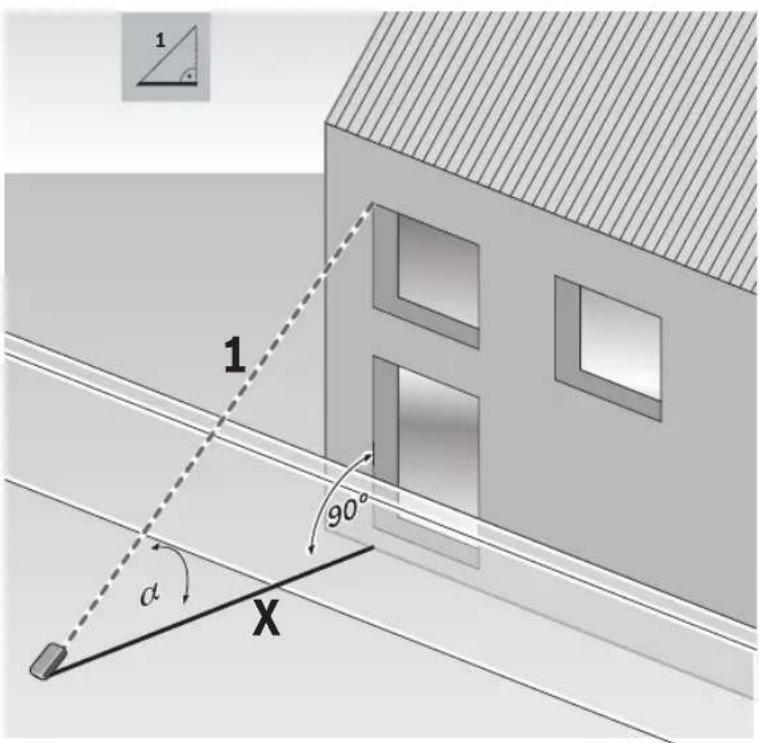
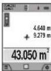
a) Indirect length measurement (see figure D)
Select the indirect length measurement mode
Ensure that the measuring tool is at the same height as the required measuring point. Then tilt the measuring tool around the reference level and measure distance 1 as for a length measurement.
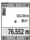
Once the measurement is complete, the result for the required distance X is displayed in the result line (a). The measured values for distance 1 and angle α can be found in the measured value lines (h).
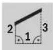
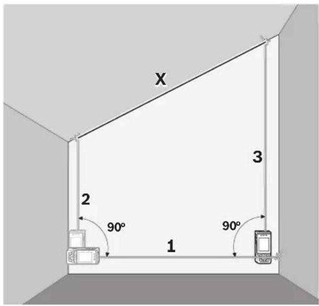
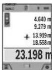
d) Trapezium measurement (see figure E)
The trapezium measurement can be used to determine the length of a roof slope, for example.
Select the trapezium measurement
Measure distances 1, 2 and 3 in succession as for a length measurement. Ensure that the measurement of distance 3 begins exactly at the point where distance 1 ends and that distances 2 and 3 are at right angles to distance 1.
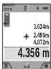
Once the final measurement is complete, the result for the required distance X is displayed in the result line (a). The individual measured values can be found in the measured value lines (h).
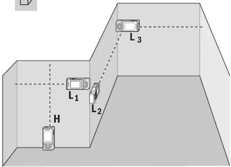
Wall area measurement (see figure F)
The wall area measurement is used to determine the sum of multiple individual areas with a common height. In the illustrated example, the total area of several walls that have the same ceiling height H but different lengths L is to be determined.
Select the wall area measurement mode □
Measure the ceiling height H as for a length measurement. The measured value is displayed in the top measured-value line. The laser remains switched on.
Then measure the length L_1 of the first wall. The area is automatically calculated and displayed in the result line (a). The last measured value for length can be found in the bottom measured value line (h). The laser remains switched on.
Now measure the length L_2 of the second wall. The individual measured value displayed in the measured value line (h) is added to the length L_1 . The sum of the two lengths (displayed in the middle measured value line (h)) is multiplied by the saved height H. The total area value is displayed in the result line (a).
You can measure any number of lengths L_x , which will be automatically added and multiplied by the height H. The requirement for a correct area calculation is that the first measured length (for example the ceiling height H) is identical for all sub-areas.
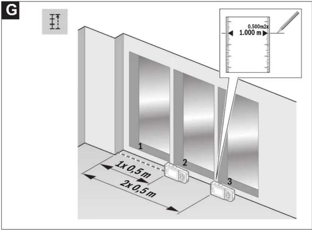
Stake out function (see figure G)
The stake out function repeatedly measures a defined length (distance). These lengths can be transferred to a surface, for example to enable material to be cut into pieces of equal lengths or to install stud walls in a drywall construction. The minimum adjustable length is 0.1 m and the maximum length is 50 m.
Note: The distance from the marking is shown in the display in the stake out function. The reference is not the edge of the measuring tool.
Select the stake out function
Use the button (4) [+] or the button (11) [-] to set the required length.
Begin the stake out function by pressing the measuring button (2) [▲] and slowly move away from the starting point.
The measuring tool continuously measures the distance to the starting point. The defined length and the current measured value are thereby displayed. The lower or upper arrow displays the shortest distance to the next or last marking.
Note: When measuring continuously, you can set a measured value as a defined length by pressing the measuring button (2) [▲]
The left factor specifies how many times the defined length has already been reached. The green arrows on either side of the display indicate the reaching of a length for marking purposes.
Red arrows or red text indicate the actual value when the reference is outside of the display.
30 | English
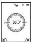
Grade measurement/digital spirit level
Select the inclination measurement/digital spirit level. The measuring tool automatically switches between two states.
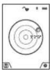
The digital spirit level is used to check the horizontal or vertical alignment of an object (e.g. washing machine, refrigerator, etc.).
When the inclination exceeds 3^ , the ball in the display lights up red.
The bottom of the measuring tool is used as a level for the digital spirit level.
the reference level for the digital spirit level.
Grade measurement is used to measure a slope or incline (e.g. of stairs, railings, when fitting furniture, laying pipes, etc.).
The left-hand side of the measuring tool serves as the reference level for grade measurement. If the display flashes during measurement, the
measuring tool has been tipped too heavily to the side.
Memory functions
The value or end result of each completed measurement is automatically saved.
Tip: When the camera is switched on, the photo is saved automatically, together with the measuring result. The following information is printed on the photo:
- Measuring result
– Individual measurements (required to determine the measuring result) - Measuring function used
- Reference
- Date and time
- Tilt angle (only with spirit level switched on).
If the photo is intended to be used for documentation purposes and transferred via micro USB cable, we recommend disabling the zoom function.
When the measuring tool is connected to an end device by micro USB cable, a csv file with all saved measured values is additionally created.
Memory value display
A maximum of 50 values (measured values or photos with measured values) can be retrieved.
Select the memory function using the soft key (12) [ ]
The number of the memory value is shown at the top of the display, the corresponding memory value and the corresponding measuring function are shown at the bottom Press the button (4) [+] to browse forwards through the saved values.
Press the button (11) [-] to browse backwards through the saved values.
If there is no value available in the memory, 0.000 is shown at the bottom of the display and 0 at the top.
The oldest value is located in position 1 in the memory, while the newest value is in position 50 (when 50 memory values are available). When a further value is saved, the oldest value in the memory is always deleted.
Deleting the memory
To open the memory, press the soft key (12) [ ], then press the soft key (3) [ ] as often as required to delete the content of the memory. To delete all values stored in the memory, the function from the settings menu can also be used. This is then confirmed by pressing the soft key (12)

Formatting the memory
The USB memory can be reformatted (e.g. in the event of storage problems). To do this, select the function from the settings menu and confirm this by pressing the soft key (12) [ ] Formatting deletes all data stored in the memory.
The USB memory must not be formatted using other devices (e.g. external PC).
Adding/subtracting values
Measured values or end results can be added or subtracted.
Adding values
The following example describes the addition of areas: Determine an area as described in the section on area measurement (see "Area measurement", page 28).
Press the button (4) [+]. The calculated area and the + symbol will be displayed. Press the measuring button (2) [▲] to start another area measurement. Measure the area as described in the section on area measurement (see "Area measurement", page 28). Once the second
measurement is completed, the result of the second area measurement is displayed below. To show the end result, press the measuring button (2) [▲] once more.
Note: In the case of a length measurement, the end result is displayed immediately.
Subtracting values
To subtract values, press the button (11) [-]. The subsequent steps are the same as for the section on adding values.
Deleting measured values
Briefly pressing the on/off/delete button (9) [∅ will delete the last measured value in all measuring functions.
Bluetooth®interface
Transmitting data to other devices
The measuring tool is fitted with a Bluetooth® module which enables wireless data transfer to certain mobile devices with a Bluetooth® interface (e.g. smartphone, tablet).
Information about the system requirements for a Bluetooth® connection can be found on the Bosch website at www.bosch-pt.com
▶ Further information can be found on the Bosch product page.
When transmitting data by means of Bluetooth ^® , time lags may occur between the mobile device and the measuring tool. This can be due to the distance between the two devices or the measurement object itself.
Activating the Bluetooth®interface for transmitting data to a mobile device
The Bluetooth® interface is activated in the settings. To activate the Bluetooth® signal, press the button (4) [+]. Ensure that the Bluetooth® interface is activated on your mobile device.
The Bosch Measuring Master app is specially designed to extend the range of functions of the mobile device and make data easier to process. This can be downloaded from the respective store of the device.
The connection between the mobile device and the measuring tool is established after the Bosch application has started. If multiple active measuring tools are found, select the appropriate measuring tool using the serial number. You can find the serial number (15) on your measuring tool's type plate.
The connection status, as well as the active connection (f), are shown in the display (1) of the measuring tool.
Deactivating the Bluetooth® interface
The Bluetooth® connection is deactivated in the settings. To deactivate the Bluetooth® signal, press the button (11) [-] or switch off the measuring tool.
USB port
Data transfer via USB port
Data can be transferred from the measuring tool to certain devices with a USB port (e.g. computer, notebook) via its micro USB connection.
Connect the measuring tool to your computer or notebook using the micro USB cable. The operating system on your computer or notebook will automatically recognise the measuring tool as a drive.
Note: When the measuring tool is connected to a computer or notebook via the micro USB cable, the Li-ion battery will charge. The charging time varies according to the charging current.
Practical advice
▶ Further information can be found on the Bosch product page.
The measuring tool is equipped with a wireless interface. Local operating restrictions, e.g. in aeroplanes or hospitals, must be observed.
General advice
The reception lens (20), the laser beam output (18) and the camera (19) must not be covered during measurement.
The measuring tool must not be moved while a measurement is being taken. For this reason, place the measuring tool against or on a firm surface whenever possible.
Influences on the measuring range
The measuring range depends on the lighting conditions and the reflective properties of the target surface. For better vis-
ibility of the laser beam in strong extraneous light, use the integrated camera (19), the laser viewing glasses (26) (accessory) and the laser target plate (25) (accessory) or shade the target area.
Influences on the measurement result
Due to physical effects, the possibility of inaccurate measurements when measuring various surfaces cannot be excluded. These include:
- Transparent surfaces (e.g. glass, water)
- Reflective surfaces (e.g. polished metal, glass)
– Porous surfaces (e.g. insulating materials) - Structured surfaces (e.g. roughcast, natural stone).
If necessary, use the laser target plate (25) (accessory) on these surfaces.
Inaccurate measurements are also possible where the laser is pointed at target surfaces diagonally.
Layers of air at different temperatures and indirectly received reflections can also influence the measured value.
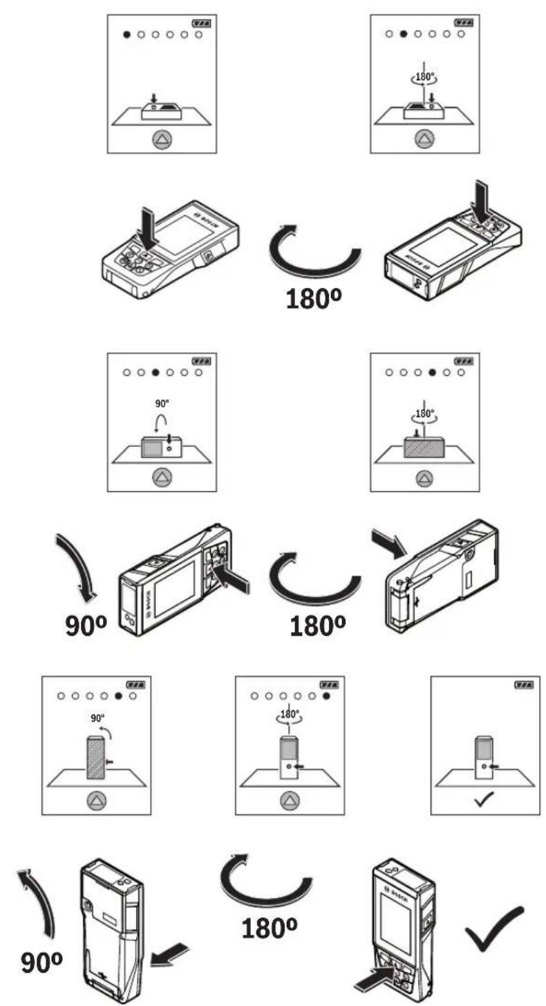
Checking accuracy and calibrating the grade measurement (see figure H)
Regularly check the accuracy of the grade measurement. This is accomplished by means of a reverse measurement. To do this, lay the measuring tool on a table and measure the inclination. Turn the measuring tool by 180° and measure the inclination again. The difference between the displayed values must not exceed 0.3°.
In case of greater deviation, the measuring tool must be recalibrated. To do so, select an the settings. Follow the directions on the display.
We recommend that you perform an accuracy check and if necessary a calibration of the measuring tool after extreme temperature variations and after impact to the tool. After a temperature variation, the measuring tool must acclimatise for a while before calibration is performed.
Accuracy check of the distance measurement
You can check the accuracy of the measuring tool as follows:
- Choose a measuring section of approx. 3 to 10m in length that is permanently unchanged, the exact length of which is known to you (e.g. room width, door opening). The measurement should be performed under favourable conditions, i.e. the measuring section should be indoors with weak backlighting and the target area of the measurement should be smooth and reflect well (e.g. a white-painted wall).
- Measure the section ten times in succession.
The deviation of the individual measurements from the mean value must not exceed ±2 mm over the entire measuring section in favourable conditions. Record the measurements in order to be able to compare the accuracy later on.
32 | English
Checking accuracy and calibrating the target indicator (crosshairs)
Check the accuracy of the alignment of the laser and target indicator on a regular basis.
- Select a bright area at least five metres away with as little illumination as possible (e.g. a white wall) as the target.
- Check whether the laser point is inside the target indicator in the display.
If the laser point is not inside the target indicator, you must recalibrate the target indicator.
To do so, select can the settings. Follow the directions on the display.
Working with the tripod (accessory)
The use of a tripod is particularly necessary for larger distances. Place the measuring tool with the 1/4" thread (17) on the quick-release plate of the tripod (27) or a conventional camera tripod. Tighten it using the locking screw of the quick-release plate.
Set the reference level for measurements with a tripod in the settings (tripod reference level).
Errors – Causes and Corrective Measures
Cause Corrective measures
Temperature warning flashes, measurement not possible
| The measuring tool is outside the operating temperature of -10°C to +45°C (in the continuous measurement function, up to +40°C). | Wait until the measuring tool has reached operating temperature. |
Display shows "ERROR"
| Addition/subtraction of measured values with various units of measurement. | Only add/subtract measured values with the same units of measurement. |
| Angle between laser beam and target is too acute. | Increase the angle between the laser beam and the target. |
| Target surface is too reflective (e.g. mirror) or not reflective enough (e.g. black material), or ambient light is too bright. | Use the laser target plate (25). |
| The laser beam output (18), reception lens (20) or camera (19) are fogged up (e.g. due to a rapid temperature change). | Wipe the laser beam output (18), reception lens (20) or camera (19) dry with a soft cloth. |
| Calculated value is larger than +1,999,999 or smaller than -999,999 m^2/m^3 . | Divide the calculation into intermediate steps. |
Cause Corrective measures
Display shows "CAL" and "ERROR"
| The calibration of the grade measurement has not been carried out in the right order or has not been carried out in the correct positions. | Repeat the calibration according to the instructions that appear on the display and in the manual. |
| The surfaces used for calibration were not precisely horizontal or vertical. | Repeat the calibration on a horizontal or vertical surface and check the surfaces beforehand if necessary using a spirit level. |
| The measuring tool has moved or tilted when the button was pressed. | Repeat the calibration and hold the measuring tool still against the surface when pressing the button. |
Battery charge indicator (g), temperature warning and "ERROR" shown in the display
| The temperature of the measuring tool is outside the permissible charging temperature range. | Wait until the charging temperature range has been reached. |
Battery charge indicator (g) and "ERROR" shown in the display
| The battery charging voltage is not correct. | Check whether the connection has been established correctly and that the charger is working properly. If the device symbol flashes, the battery is defective and must be replaced by the Bosch after-sales service. |
Measurement result implausible
| Target surface reflection not distinct (e.g. water, glass). | Cover the target surface. |
| The laser beam output (18), reception lens (20) or camera (19) is covered. | Keep the laser beam output (18), reception lens (20) and camera (19) clear. |
| An incorrect reference level has been set. | Select a reference level that is appropriate for the measurement. |
| Obstruction in the path of the laser beam. | The laser point must be fully on the target surface. |
Bluetooth® cannot be activated
| The battery is too weak. Charge the battery of the measuring tool. |
No Bluetooth® connection
| There is a problem with theBluetooth®connection. | SwitchBluetooth®off and back on again on the measuring tool and mobile device. |
| Check the application on your mobile device. |
Cause Corrective measures
Check whether Bluetooth® is activated on your measuring tool and mobile device.
Check whether your mobile device has been overloaded.
Reduce the distance between the measuring tool and your mobile device.
Where possible, ensure that there are no obstructions (e.g. reinforced concrete, metal doors) between the measuring tool and your mobile device. Keep the equipment away from any sources of electromagnetic interference (e.g. WiFi transmitters).
Data transfer via USB port not possible
Micro USB cable Check that the micro USB
cable has been inserted correctly and securely.
Check that the micro USB cable has not been damaged in any way.

The measuring tool monitors for correct operation in every measurement. If a defect is detected, the display will indicate only the symbol shown opposite. In this case, or if you are unable to rectify an error using the corrective
measures above, send the measuring tool to Bosch customer service via your dealer.
Maintenance and Servicing
Maintenance and Cleaning
Keep the measuring tool clean at all times.
Never immerse the measuring tool in water or other liquids. Wipe off any dirt using a damp, soft cloth. Do not use any detergents or solvents.
Clean the reception lens (20), laser beam outlet aperture (18) and camera (19) particularly carefully: Ensure that there is no dirt on the reception lens, the laser beam outlet aperture or the camera. Only clean the reception lens, the laser beam outlet aperture and the camera with cleaning agents that are also suitable for camera lenses. Do not attempt to remove dirt from the reception lens, laser beam outlet aperture or camera using pointed objects, and do not wipe over the reception lens, laser beam outlet aperture or camera (risk of scratching).
If the measuring tool needs to be repaired, send it off in the protective bag (24).
After-sales service and advice on using products
Our after-sales service responds to your questions concerning maintenance and repair of your product as well as spare parts. You can find explosion drawings and information on spare parts at: www.bosch-pt.com
The Bosch product use advice team will be happy to help you with any questions about our products and their accessories.
In all correspondence and spare parts orders, please always include the 10-digit article number given on the nameplate of the product.
Great Britain
Robert Bosch Ltd. (B.S.C.)
P.O. Box 98
Broadwater Park
North Orbital Road
Denham Uxbridge
UB 9 5HJ
At www.bosch-pt.co.uk you can order spare parts or arrange the collection of a product in need of servicing or repair.
Tel. Service: (0344) 7360109
E-Mail: boschservicecentre@bosch.com
Ireland
Origo Ltd.
Unit 23 Magna Drive
Magna Business Park
City West
Dublin 24
Tel. Service: (01) 4666700
Fax: (01) 4666888
Australia, New Zealand and Pacific Islands
Robert Bosch Australia Pty. Ltd.
Power Tools
Locked Bag 66
Clayton South VIC 3169
Customer Contact Center
Inside Australia:
Phone: (01300) 307044
Fax: (01300) 307045
Inside New Zealand:
Phone: (0800) 543353
Fax: (0800) 428570
Outside AU and NZ:
Phone: +61 3 95415555
www.bosch-pt.com.au
www.bosch-pt.co.nz
Supplier code ERAC000385
Republic of South Africa
Customer service
Hotline: (011) 6519600
Gauteng - BSC Service Centre
35 Roper Street, New Centre
Johannesburg
Tel.: (011) 4939375
Fax: (011) 4930126
E-mail: bsctools@icon.co.za
34 | Français
KZN - BSC Service Centre
Unit E, Almar Centre
143 Crompton Street
Pinetown
Tel.: (031) 7012120
Fax: (031) 7012446
E-mail: bsc.dur@za.bosch.com
Western Cape - BSC Service Centre
Democracy Way, Prosperity Park
Milnerton
Tel.: (021) 5512577
Fax: (021) 5513223
E-mail: bsc@zsd.co.za
Bosch Headquarters
Midrand, Gauteng
Tel.: (011) 6519600
Fax:(011)6519880
E-mail: rbsa-hq.pts@za.bosch.com
Disposal
Measuring tools, accessories and packaging should be recycled in an environmentally friendly manner.

Do not dispose of measuring tools with household waste.
Only for EU countries:
According to the Directive 2012/19/EU, measuring tools that are no longer usable, and according to the Directive 2006/66/EC, defective or used battery packs/batteries, must be collected separately and disposed of in an environmentally correct manner.
Batteries:
▶ Integrated batteries may only be removed for disposal by qualified personnel. Opening the housing shell can destroy the measuring tool.
Make sure that the battery is fully discharged before removing it.
Make sure that the battery is fully discharged before removing it. Remove the rating plate, open the measuring pin and remove all the screws on the reverse side of the housing. Remove the housing shell, detach all the cables from the circuit board and undo the screws. You can now remove the circuit board and the battery will be visible. Loosen both screws and remove the battery in order to dispose of it properly.
Even when fully discharged, the battery still contains a residual charge that can be released in the event of a short circuit. Do not dispose of the batteries by throwing them out with household waste, on a fire or into water. After running down their charge (where possible), batteries should be collected and recycled or disposed of in an environmentally friendly manner.
Français
(22) Câble micro-USB
(22) Cable micro USB
(23) Cargador ^4
Calle Robert Bosch No. 405
This equipment has no right to protections against prejudicial interference and cannot cause interference on systems duly authorized.
Italiano
(9) Toets Aan/Uit/Wissen [Φ]
(10) Cameratoets
(9) Tasten Tænd/Sluk/Slet [∅]
(10) Kamera-tast
Menuen "Indstillinger"
Bosch Service Center
Telegrafvej 3
2750 Ballerup
På www.bosch-pt.dk kan der online bestilles reservedele eller oprettes en reparations ordre.
Tlf. Service Center: 44898855
Fax: 44898755
E-Mail: vaerktoej@dk.bosch.com
Bortskaffelse
Bosch Service Center
Telegrafvej 3
2750 Ballerup
Danmark
Tel.: (08) 7501820 (inom Sverige)
Fax: (011) 187691
Avfallshantering
Apparatinnstillinger
| Språk |
124 | Norsk
Apparatinnstillinger
Robert Bosch Sp. z o.o.
Bosch Service Center PT
K Vápence 1621/16
692 01 Mikulov
Service scule electrice
Strada Horia Măcelariu Nr. 30–34, sector 1
013937 Bucureşti
Service scule electrice
Strada Horia Măcelariu Nr. 30-34, sector 1
013937 Bucureşti, România
www.bosch-pt.com/bg/bg/
Бракуване
(m) Nazad (Soft taster)
(n) Početni ekran (Soft taster)
Bluetooth® interfeiss
NZDYIKI DSTKASHEAI YRSHKI, YIMP BNZIN,
The Ground Truth image displays a single, solid horizontal line. According to Rule 2 (UNDERSCORE & LINE RULES), this is a stylistic or background line, not a placeholder underscore. Therefore, the OCR result must ignore it and output nothing or only meaningful text. The provided OCR content is "____", which consists of four underscores. This is an incorrect interpretation of the line as a placeholder, violating the rule that stylistic lines must be ignored. The OCR has hallucinated placeholder underscores where none should exist in the GT. Hence, the OCR result is inconsistent with the Ground Truth.


- GLM 120 C Professional
- BOSCH
- Deutsch
- Sicherheitshinweise
- Safety instructions for chargers
- Product Description and Specifications
- Intended Use
- Product features
- | English
- Display elements
- Initial start-up
- Charging the battery
- Recommendations for optimal handling of the battery in the measuring tool
- Operation
- Start-Up
- | English
- Switching On/Off
- Camera
- Optimising visibility of the laser point
- Measuring process
- Selecting the reference level (see figure A)
- Continuous laser beam
- ▶ Do not direct the laser beam at persons or animals and do not stare into the laser beam yourself (even from a distance).
- Settings menu
- Timer function
- Tool settings menu
- Setting the language
- Setting the date and time
- Changing the unit of measurement
- Changing the unit of measurement of an angle
- | English
- TrackMyTools
- Display illumination
- Measuring functions
- Note: Integrated help function
- Measuring length
- Continuous measurement
- Area measurement
- Volume measurement
- Indirect distance measurement
- a) Indirect height measurement (see figure B)
- b) Double indirect height measurement (see figure C)
- a) Indirect length measurement (see figure D)
- d) Trapezium measurement (see figure E)
- Wall area measurement (see figure F)
- Select the wall area measurement mode □
- Stake out function (see figure G)
- | English
- Grade measurement/digital spirit level
- Memory functions
- Memory value display
- Deleting the memory
- Formatting the memory
- Adding/subtracting values
- Adding values
- Subtracting values
- Deleting measured values
- Bluetooth®interface
- Transmitting data to other devices
- ▶ Further information can be found on the Bosch product page.
- Activating the Bluetooth®interface for transmitting data to a mobile device
- Deactivating the Bluetooth® interface
- USB port
- Data transfer via USB port
- Practical advice
- General advice
- Influences on the measuring range
- Influences on the measurement result
- Checking accuracy and calibrating the grade measurement (see figure H)
- Accuracy check of the distance measurement
- | English
- Checking accuracy and calibrating the target indicator (crosshairs)
- Working with the tripod (accessory)
- Errors – Causes and Corrective Measures
- Cause Corrective measures
- Data transfer via USB port not possible
- Maintenance and Servicing
- Maintenance and Cleaning
- After-sales service and advice on using products
- Great Britain
- Ireland
- Australia, New Zealand and Pacific Islands
- Republic of South Africa
- Customer service
- Gauteng - BSC Service Centre
- | Français
- KZN - BSC Service Centre
- Western Cape - BSC Service Centre
- Bosch Headquarters
- Disposal
- Only for EU countries:
- Batteries:
- Français
- Italiano
- Menuen "Indstillinger"
- Bortskaffelse
- Avfallshantering
- | Norsk
- Бракуване
- Bluetooth® interfeiss
Brand : BOSCH
Model : GLM 120 C Professional
Category : Rangefinder